1
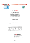
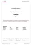
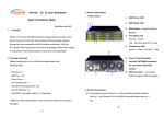
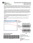
NA265A
External PCIe 3.0 to GPU Rackmount Enclosure
3. Panel Layout
1. Overview
10
The easy, cost-effective Netstor PCIe Gen3 to GPU rackmount
1. Slot 1 : PCIe ×16 connector (×16 signal);
expansion enclosure TurboBox NA265A features easy plug and play
target card already installed in it.
installation, containing PCIe 3.0 ×16 host card, target card and data
2. Slot 2 : PCIe ×16 connector (×8 signal)
cable providing high-speed data rate up to 128Gbps. Through the
3. Slot 3 : PCIe ×16 connector (×8 signal)
TurboBox NA265A, all the PCIe slots on NA265A are available to the
4. Slot 4 : PCIe ×16 connector (×8 signal)
host PC, server, or workstation.
5. Slot 5: PCIe ×16 connector (×8 signal)
6. Slot 6: PCIe ×4 connector (×4 signal)
2. Package Checklist
43 2 1
Before the installation of this unit, verify the package contains the
following items.
5 6
1. Power on/off button
7. Slot 7: PCIe ×4 connector (×4 signal)
7 8 9
8. 8* 6+2 pin PCIe power cables for graphics cards
Blue – power on
Note: Under powering on/off NA265A by manual mode, to
power on/off the TurboBox NA265A, press the button for two
seconds until the button shows blue light or off.
4. Installation of PCIe Graphics/Add-On
Card and Connection
Before following the installation procedures, disconnect
TurboBox NA265A from power source to prevent electric
shock or damage to graphics/PCIe card. In order to
correctly configure NA265A to work properly with different
host PC or Workstation, the following jumper and switches
may need to be adjusted.
2. Buzzer mute button
3. Fan LED
Green – normal
Red – fan failure (low frequency of RPM or stop)
A
NA265A Enclosure x 1
PCIe 3.0 ×16
host adapter card x 1
B
4. Temperature LED
Green – normal
Red – over-temperature (higher than 55℃)
5. Power switch (single PSU)
PCIe 3.0 ×16 target
adapter card x 1 (Installed)
D
PCIe 3.0 ×8 cable
(1.5 meter) x 2
Power cord × 1 (single PSU)
/ × 3 (redundant PSU)
F
Function
To set up connection between host and
NA265A for ×8 or ×16. For ×16 connection,
SW1-2 is ON. For ×8 connection, SW1-2 is
OFF.
Location
Switch SW1-2 is located near slot 5 on
backplane.
Function
To set up connection between host and NA265A
for ×8 or ×16. For ×16 connection, SW1 is OFF.
For ×8 connection, SW1 is ON.
Location
Switch module SW1 is located on top-right
position of host card (NP970A-H) and target
card (NP970A-T).
8. Two external PCIe 3.0 ×8 connectors for host connection
(one port is etched with ×8 for lane 1~8; the other port is
etched with ×16 for lane 9~16)
SW1
10. Thumbscrew to loosen/tighten the top cover
NetStor Technology Co. Ltd.
www.netstor.com.tw
E
Jumper JP2 is located near slot 3 on
backplane.
SW1-2
9. PCIe slots
Green IT makes
Green Earth
Location
6. Power receptacle
7. Link status LED
Gen3: constant green light
Gen2: fast blinking green light (2 flashes/second)
Gen1: slow blinking green light (1 flash/second)
C
Function
To set NA265A to Gen3 mode, place jumper
over pin 1 and pin 2. To set NA265A to
Gen2 mode, NOT place jumper over pins.
To set NA265A to Gen1 mode, place
jumper over pin 2 and pin 3.
JP2
8
CD containing
user manual x 1
1. The PCIe slot of host PC, workstation or Mac Pro that
links with NA265A must be identified first for correct
connection between host and NA265A.
Four conditions A, B, C, and D for connection are
listed below:
•inside
If any of the above items is missing or damaged, please notify your sales
representative.
7 6
5 43
2
1
1627 3
4
5
NA265A
External PCIe 3.0 to GPU Rackmount Enclosure
(A) If the PCIe slot of host PC, workstation that works with
NA265A is PCIe 3.0 ×16, set (this is the default setting)
JP2 at Gen3.
SW1-2 at ON.
Each GPU card in NA265A is provided with two 6+2 pin PCIe
power cables for extra power resource. Up to 4 double-width,
full-length GPU cards can be installed in slot 2, slot 3, slot 4,
and slot 5 in enclosure.
(B) For Mac Pro, host PC, or workstation whose PCIe slot is
PCIe 2.0 ×16 that is used to work with NA265A, set
JP2 at Gen2,
SW1-2 at ON.
(C) If the PCIe slot of host PC, workstation that works with NA265A
is PCIe 3.0 ×8, set
JP2 at Gen3,
5. Put the top cover back to TurboBox NA265A, and tighten
the two thumbscrews to fasten the top cover.
SW1-2 at OFF,
SW1 on host card and target card at ON.
(D) If the PCIe slot of host PC, workstation that works with
NA265A is PCIe 2.0 ×8, set
JP2 at Gen2,
6. Connect one end of two PCIe ×8 data cables to PCIe ×8
connectors on rear of NA265A.
SW1-2 at OFF,
SW1 on host card and target card at ON.
After identifying the PCIe slot in computer that
links with NA265A and making the correct
setting as one of the four conditions listed
above, install the host card NP970A-H onto
the PCIe slot in host PC, workstation or
Mac Pro.
7. Connect the other end of two PCIe ×8 data cables to the
two PCIe ×8 connectors on NP970A-H host card on host
PC, workstation, or Mac Pro.
Note: Make straight connection between host card and target
card with mark ×8 to ×8, and ×16 to ×16. DO NOT make
cross connection.
motherboard
2. Loosen the two thumbscrews and remove the top cover
from TurboBox NA265A.
8. Connect the end of power cord to power receptacle on
TurboBox NA265A and the other end of power cord to
grounded outlet or power strip.
x16 x8
x16
x8
3. Remove the L shape metal bracket on rear of TurboBox
NA265A by unscrewing the screw of metal bracket for
installing the graphics or PCIe card on NA265A.
4. Install one graphics/PCIe card into one PCIe ×16 slot in
NA265A and tighten it with a screw.
There are three hot-swappable 90×90×25 mm cooling fans for
ventilation inside TurboBox NA265A. The cooling fan can be
taken out by unscrewing the thumbscrew on the fan module.
5. Fan Speed Adjustment
The fan speed of the front 90×90×25 mm cooling fan of
NA265A can be adjusted. Pull out the fan module, on the
connector of cooling fan, there are five sets of jumpers
labeled with 4, 3, 2, 1 and F from top to bottom on the fan
connector board. The default setting is the jumper being
placed over pin 9 and 10 for label 4 for slowest speed.
The speed increases from label 3 to label F. When jumper is
not placed over pins, the fan will not spin.
9
10
7
8
5
6
3
4
1
2
6. Powering On/Off TurboBox NA265A
There are two ways to power on/off the NA265A. One is to
power on/off NA265A by host (the default setting); the other
is to power on/off NA265A by manual. Configure switch
SW1-1 near slot 5 on backplane for setting. For powering
on/off by host, switch SW1-1 to “ON” position. For powering
on/off by manual, switch SW1-1 to “OFF” position.
When NA265A is set for powering on/off by host, the NA265A
will be automatically powered on and off with the
host computer. When NA265A is set for powering on/off by
manual, the standard powering on/off procedure below must
be followed:
(1) Power on TurboBox NA265A by
pressing the power button for
two seconds until the button
shows blue light.
(2) In order to let the BIOS of host PC, workstation, or
Mac Pro identify and assign resources appropriately,
always power on NA265A first, and then power on
host PC, workstation, or Mac Pro.
(3) To remove TurboBox NA265A from host PC, workstation,
or Mac Pro, power off host PC, workstation, or Mac Pro
first, and then power off NA265A.
NA265A
External PCIe 3.0 to GPU Rackmount Enclosure
7. Verify Installation
‧For Windows operating system
When you want to verify a successful installation on Windows
operating system, go to Computer and right click the icon of
Computer. Select Manage from the menu (see figure 1), and click
Device Manager in the left side of window of Computer M
anagement (see figure 2).
Figure 1
Figure 2
And then click View from the top side of the window,
and select Devices by connection.
Open ACPI Multiprocessor PC, open Microsoft ACPI-Compliant
System, and then open PCI bus. Click PCI Express Root Port,
click PCI standard PCI-to-PCI bridge, and then click the
next-tier PCI standard PCI-to-PCI bridge. Then the
graphics/PCIe card installed in NA265A will appear below the
bottommost-tier PCI standard PCI-to-PCI bridge.
There will be PCI Express Root Ports with different ending
numbers such as 1C10, 1C18, 1C1A and 0101. These different
ending numbers indicate the different PCIe slots on motherboard.
No software is required for configuration of NA265A by
operating system of host PC, workstation, or Mac Pro, but
when a GPU or PCIe card is installed in NA265A, a request
for the driver of the GPU or PCIe card will be prompted by the
operating system. Please follow the driver installation
instruction given by GPU/PCIe card.
Click More Info… button, and then click System Report…
button in the pane.
If there is a yellow exclamation mark in front of the GPU/PCIe
card below PCI standard PCI-to-PCI bridge, it means the driver
for the GPU/PCIe card has not been installed. Therefore,
the driver needs to be installed on operating system to let
GPU/PCIe work with host PC or workstation.
After the driver is installed on operating system, the
GPU/PCIe card will work properly with host PC or workstation
through NA265A, and the GPU/PCIe card will appear below the
bottommost-tier PCI standard PCI-to-PCI bridge as well as in
the list of Device Manager.
Note: Whether or not a motherboard supports 4 GPU cards depends
on the firmware of the BIOS of motherboard. Consult with the
manufacturer of motherboard about whether the resource of BIOS
supports 4 GPU cards.
Click PCI Cards on the left side of pane. It will show four
(when upstream port is set for ×16) or six (when upstream port
is set for ×8) pci-bridges that indicate the four or six PCIe slots
in NA265A in the information field.
When a graphics/PCIe card is installed in one of the PCIe slots
in NA265A, the graphics/PCIe card will appear below the four
or six pci-bridges.
‧For Mac OS X
For certain model of Mac Pro, when GPU/PCIe card is installed
in PCIe slot in NA265A, the information field will appear blank in
PCI Cards section in System Information on OS X, but the
GPU/PCIe card does work properly.
To verify a successful installation on Mac OS X, select About
This Mac under the Apple icon.
After the installation of the driver of graphics/PCIe card on
Mac OS X, the graphics/PCIe card starts to work with Mac Pro
through NA265A.
Netstor Technology Co., Ltd.
Four PCI standard PCI-to-PCI bridges will appear below the
PCI Express Root Port when upstream port (slot 1) is set
for ×16. And six PCI standard PCI-to-PCI bridges will appear
below the PCI Express Root Port when upstream port is set
for ×8.
6F, No. 1, Alley 16, Lane 235, Baoqiao Rd.,
Xindian District, New Taipei City 231-45, Taiwan, R.O.C.
Tel: +886-2-2917-1500 Fax: +886-2-2918-1260
E-mail: [email protected]