1
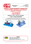
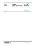
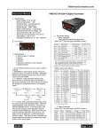
PID Temperature Controller*
Model WSD-30A
User Manual
Version 1.1, Jan. 2014
Doccol Corporation
30 Eisenhower Drive, Sharon, MA 02067-2427, USA
Tel: (888) 481-0842; Fax: (888) 893-5285; www.doccol.com
A. Introduction
The PID temperature controller model WSD-30A is featured with low voltage direct current (DC) output for using
with a low noise DC-powered heating plate. It allows accurate electrophysiological recording with minimal
electromagnetic field interference (EMF). This controller offers higher sensitivity and precision than the RTD and
thermocouple sensor based controllers by using thermistor type sensor. It is equipped with a rectal temperature
probe suitable for both mice and rats, and a temperature senor on the heating plate for limiting the maximum
surface temperature to avoid over-heating or burn injury. The setting for the maximum surface temperature limit
can also be adjusted and viewed by the user. Below is the summary of specifications.
B. Specifications
Input voltage
Output voltage
Control Mode
Output switching device
100 to 240 VAC 50 /60 Hz
12 VDC, 4A Max.
PID, PI, PD or P.
Built-in optically isolated solid state relay
Sensor probe dimensions
Rectal probe
Probe cable length
2 mm diameter x 30 mm long.
1.2 meter.
Temperature resolution
Temperature display range
Mini. Control Temperature
Max. Control Temperature
Temperature accuracy
Dimension
Weight
Heating Plate Dimension
Heating Plate Wattage
Warranty
0.1 °C
0-99.9 °C
5 °C above ambient.
99.9C.
+/- 0.1°C (in 25-40 C range)
6x3x8.3 inch (155 x80x210 mm) WxHxD.
3.2lb (1.4 kg).
250 x150 mm
30W at 12VDC
1 year for controller. 90 days for sensor
C. Operating Instructions
In particular, we would urge you to read through the safety warnings below. Although this plug-and-play controller
is very easy to operate, your safety is paramount.
SAFETY WARNINGS
• This controller was designed to be used only with the equipped heating plate. Do not connect with an
untested heating device. Using it to control a non-recommended device can be dangerous and may cause
fire. Doccol Corporation is not liable for damages caused by misuse of the controller.
• Do not place any objects on the top of controller surface that is used to vent excess heat during its
operation.
• If an abnormal display or noise is observed, turn the controller off, unplug the power cord and contact the
manufacturer before using it again.
• Clean the controller only when it is cool and unplugged.
1. Description of the controller.
Doccol Corporation, 30 Eisenhower Drive, Sharon, MA 02067-2427, Tel: (888) 481-0842; Fax: (888) 893-5285, www.doccol.com
Page 1 of 6
PID Temperature Controller*
Model WSD-30A
1) TEMP1, Left window. During normal operation, it displays the temperature values of probe. When high or
low limit alarm of rectal probe is on, this window will flash the alarm type (AH1or AL1) and the temperature
alternatively. In the parameter setting mode, it displays the controller's system parameters.
2) TEMP2/TIME, Right window. During normal operation, it displays the Set temperature, or the surface
temperature of heating plate. When high limit alarm of the probe inside heating pad is on, this window will
flash AH2 and the temperature alternatively. In the parameter setting mode, it displays the value of the
parameter.
3) Output status indicator. This LED indicates the power output status to the heating pad. When it is on (lit),
the heating pad is powered. When it is off, the heating pad power is off. When it is flashing, it means the
power is on and off intermittently to reduce the power output.
4) This indicator is not used.
5) Heating pad temperature indicator. When it is lit, the right window shows the surface temperature of the
heating plate. When it is off, the right window shows the set temperature of the rectal probe.
6) SET Key. This is the parameter setting key for showing current temperature settings, getting into
parameters setting mode and confirming various actions taken.
7) “-” Key. Pressing it to decrease displayed value when the controller is in the parameter setting mode.
During normal operation, pressing it will cancel the alarm.
8) “+” Key. Pressing it to increase displayed value when the controller is in the parameter setting mode.
During normal operation, pressing it will change the left window from displaying temperature to displaying
program parameter.
9) Right window control Key. Pressing it to switch the display in right window between the set temperature of
the rectal probe and the surface temperature of the heating plate.
Back Panel
Front Panel
2. Connecting and operating the controller
1.) Connecting the power cable of the controller directly to the wall outlet.
2.) Connect the controller power output to the heating pad.
3.) Connecting the rectal probe to the probe socket. Insert the rectal probe into the rectum of the animal to be
controlled.
4.) Turning on the power switch on the back panel of the controller.
3. Programming the temperature controller
There are two temperature parameters to be set: C01 is the set value for the temperature at the rectal probe tip.
C02 is the set value for the maximum temperature allowed at the heating pad surface. It prevents the heating pad
from getting too hot.
For example, when setting C01=37.0 ⁰C, C02=40.0 ⁰C, if the probe reading < C01 and heating pad reads < C02,
the controller will send power to the heating pad to warm it up. But if the heating pad reached 40.0 ⁰C before the
rectal probe reaches 37.0 ⁰C, the heater will start to shut off so that heating pad is kept not over 40.0 ⁰C.
To set the temperature, press SET key once. The display will show C01 at the left window and temperature setting
on the right window for step 1. Use “+” and “-” keys to change the setting. When finished, press the SET again to
confirm the change. The display will show C02 on the left window and the temperature setting on the right window.
Use “+” and “-” keys to change the setting. When finished, press the SET again to confirm the change. The
temperature setting will not be changed if SET is not pressed (confirmed). After having set C02 the display will
return to the normal display mode.
Doccol Corporation, 30 Eisenhower Drive, Sharon, MA 02067-2427, Tel: (888) 481-0842; Fax: (888) 893-5285, www.doccol.com
Page 2 of 6
PID Temperature Controller*
Model WSD-30A
Table 1. Initial program setting
Description
Parameter
Temp (⁰C)
C01
Rectal Probe temp set point (0-99.9 ⁰C)
37.0
C02
Heating pad maximum temp limit (0-99.9⁰C)
40.0
4. Check the heating pad temperature
When the controller is running, pressing the "TIME" key (9) will switch the right window from displaying the rectal
probe set temperature to the actual temperature of the heating pad. The "Time" LED indicator (5) will light also.
Pressing it again will switch back to the rectal probe set temperature.
5. Tuning the controller
The PID parameter of this controller is preset for the heating pad that shipped with the controller. If you feel that
performance is not ideal, you can try to manually tune the system or run the auto-tune again. For detailed
information on how to tune the controller, please read the section 7 and 8 for tuning the controller.
6. Controller Parameter set up.
The controller parameters are divided into three groups.
1) The first group of parameter is related to the control performance. They need to be adjusted basing on the
connected heating device and animal size. Table 2 shows the list of these parameters, their ranges and initial set
values when the controller left the factory.
Table 2. List of control parameters and its initial settings under code 166
Symbol
Display
Description
Range
Initial
P
p
Proportional band (in 0.1 degree)
0-600
2
I
I
Integral constant (second)
0-900
2
d
d
Derivative constant (second)
0-300
100
AT
At
Auto-tune
0=off 1=on
0
T
t
Cycle rate (second)
1-100
2
HY1
Hy1
Hysteresis band for probe
0.1-60.0
0.1
HY2
HY2
Hysteresis band for heating pad
0.1-60.0
0.5
Details about each parameter
• P, proportional band. It is in 0.1 degree unit. This parameter control the output of the controller based on
the difference between the measured and set temperature. Larger the P number means the weaker the
action (lower gain). When the sensor temperature is 10 degrees below the proportional band (10 degrees
below the setting), the controller will have 100% output. When the temperature is 5 degree below the set
point, the output is 50%. When the temperature is equal to the setting, the controller will have 0% output
(assuming integral and derivative functions are turned off). This constant also affects both integral and
derivative action. Smaller P values will make the both integral and derivative action stronger. Please note
the value of the P is temperature unit sensitive. If you found an optimized P value when operating the
controller in Celsius, you need to multiply the P by 1.8 when changing the temperature unit to Fahrenheit.
• I, integral time. The unit is in second. This parameter controls the output of controller based on the
difference between the measured and set temperature integrated with time. Integral action is used to
eliminate temperature offset. Larger number means slower action. When temperature fluctuates regularly
(system oscillating), increase the integral time. Decrease it if the controller is taking too long to eliminate
the temperature offset. When I=0, the system becomes a PD controller.
• d, derivative time. The unit is in second. Derivative action contributes the output power based on the rate
of temperature change. Derivative action can be used to minimize the temperature overshoot by
responding its rate of change. The larger the number is, the faster the action will be. The derivative action
change the controller output based on the rate of change rather than the net amount of change. This will
allow the controller to act sooner. It will turn the heater to full power before the temperature drops too
much.
Doccol Corporation, 30 Eisenhower Drive, Sharon, MA 02067-2427, Tel: (888) 481-0842; Fax: (888) 893-5285, www.doccol.com
Page 3 of 6
PID Temperature Controller*
•
•
•
•
Model WSD-30A
AT, auto-tune. See above auto-tune section.
T, cycle rate. The unit is in second. This unit determines how long for the controller to calculate each action.
This parameter should remain at 2 second for almost all applications.
Hy1 is the hysteresis band for the probe setting when controller is set to on/off mode (P=0). This parameter
is not used in the normal PID mode.
Hy2 is the hysteresis band for the heating band. If the heating pad is set at SV2. The heater will turn off at
SV2 and turn on again when temperature drop to SV2-Hy2. For example, it the heating pad maximum
temperature is set at 40 degree and Hy2 is set at 0.5, the heater will shut off when heating pad is reached
40.0 degree and turn on again when temperature dropped to 39.5 degree.
To prevent changing critical parameters by accident, an access lock, LCK is used. Special code is needed to open
the lock for these parameters. This group of parameters is accessed by input code 166.
Press and hold SET key for 4 seconds until LED displays “LCK” on the left window, then release the SET key. The
display on the right window will show “0”. To get into parameters setting mode, you need to key in the pass code.
Use “+” and “-“keys to adjust the display to 166 (which is the pass code) and press SET. The left window will then
display “P” and right window is P setting value, Use “+” and “-“ keys to change the setting. When finished, press the
SET again to confirm the change. The left display will then show the “I“ right window has its setting value, use the
same “P” setting procedure to set the I value. The rest of parameters are set in the same way.
2) The second group is about the system configuration. Once they are set, they normally do not need to be
changed. This group of parameters can be accessed by inputting code 155. Table 3 shows the list of the
parameters, their ranges and initial set values when the controller left the factory.
Table 3. List of control parameters and its initial settings under code 155
Symbol
Display
Description
Range
Initial
SC1
Sc1
Probe sensor offset (in degree)
-19.9~+20.0
0
SC2
SC2
Heating pad sensor offset (in degree)
-19.9~+20.0
0
Output power reduction (%)
1-100
100
Out
Details about each parameter.
• SC, calibration offset. The parameter is used to make the input offset to compensate the error produced by
sensor. If the temperature displays of probe is 1.0 °C higher than a calibrated thermometer, set SC=-1.0
will make the display match the calibrated thermometer. SC1 is for the rectal temperature probe. SC2 is for
the sensor in the heating pad.
• Out, output power reduction. It is expressed as a percentage value. This function will allow you to control
the maximum output power delivered by the heater. For example, if you set Out=50 and your heater is 30
watts, the output will use 50% of the 30 watts as the full output. It treats the 30W heater as a 15W heater.
When the PID algorithm determines 20% output value, the actual power output will be 3W.
Press and hold SET key for 4 second until the left window displays “LCK”, then release the SET key. The right
window will show “0”. Use “+” and “-” keys to adjust the display to 155 (another pass code) and press SET. The left
window will show the parameter and right window will show its value. Use “+” and “-” keys to change the setting.
When finished, press the SET to confirm the change, then the next parameter will be displayed.
3) The third group is about the alarm. The alarm setting can be accessed by inputting code 188.
Table 4 shows the list of the parameters, their ranges and initial set values when the controller left the factory.
Table 4. List of control parameters and its initial settings under code 188
Symbol
Description
Range
Initial
AH1
Probe high limit alarm
0-99.9 °C,
40.0
AL1
Probe low limit alarm
0-99.9 °C,
0
AH2
Heating pad high limit alarm
0-99.9 °C,
40.0
Detail of each parameter.
• AH1, this is the high limit alarm for probe 1. User can set the temperature so that if the system is out of
control, the buzzer will be turned on. e.g. If AH1 set to 38.0, the buzzer will be on at 38.0 and off at 37.0.
When the buzzer is on, the left widow will flash alternatively between AH1 and the current temperature.
Doccol Corporation, 30 Eisenhower Drive, Sharon, MA 02067-2427, Tel: (888) 481-0842; Fax: (888) 893-5285, www.doccol.com
Page 4 of 6
PID Temperature Controller*
Model WSD-30A
•
AL1 is the low limit alarm for probe 1. e.g. If AL1 is set to 25. The buzzer will be turned on when
temperature drop to 25. It will be turned off when temperature rise to 26. This alarm is suppressed when
first powered up. It will only function after the temperature has reached set point once. When the buzzer is
on, the left window will flash alternatively between AL1 and the current temperature.
• AH2 is the high limit alarm for the heating pad. If AH2 is being set to 41, the buzzer will be turned on at 41
and off at 40. When the buzzer is on, the right window will flash alternatively between AH2 and the current
temperature.
Note: All alarm can be cancelled during beeping by press the “-” key.
Press and hold SET key for 4 second until left window displayed “LCK”, then release the SET key. The right
window will show “0”. Use “+” and “-” keys to adjust the display to 188 (pass code) and press SET. The left window
now will show the parameter and right window will show its value. Use “+” and “-” keys to change the setting. When
finished, press the SET to confirm the change. The next parameter will be displayed.
7. Auto-Tune
1). Auto-Tune
The controller's most powerful feature is its ability to regulate virtually any heater with stable temperature control.
For stable temperature control the controller requires two things; (1) the controller must be set to the correct power
level (see next section) and, (2) that it must be tuned to the heater being used. Tuning is the process that matches
the control characteristics of the controller to the heating characteristics of the heater. The controller is said to be
tuned to the heater when its memory is programmed with values telling it how fast the heater warms up, cools off,
and how efficiently it transfers heat. Describing how fast the heater heats when electricity is turned on and how fast
it begins to cool when it's turned off. These time constants are called the tuning parameters.
Every type of heater has its own unique set of tuning parameters. For the controller to heat with stability, it must
have been programmed with the tuning parameters for the heater to be used.
2). Use auto-tune function to optimize controller performance settings
The controller is pre-tuned to work with our heating pad and 1 anesthetized adult mouse. You may use the
auto-tuning function to let the controller to determine the PID parameters for other experimental conditions
automatically. Auto-tuning function (it’s often known as self-tuning) can automatically optimize the PID parameters
for your chosen heating system. The auto-tuning function will heat up your heater then let it cool down. It will repeat
this heat/cool cycle several times. Based on the response time of the whole heating system, the controller will
calculate and set the PID parameters for your heater.
Before using the auto-tune function, you must set the heating equipment up in the exact configuration it should be
used. Turn the controller and heater on, and then enter the desired target temperature close to your normal use
temperature.
To activate auto-tuning, just enter code 166 to get into the PID setting menu. Set AΓ to 1 then exit the menu. The
display will start to flash alternately between AΓ and current temperature, which indicates auto-tuning is in progress.
When the display stops flashing, the auto-tuning is finished. Now, the newly calculated PID parameters are set and
are used for the system. The new parameters will store in the memory even the power is off.
*Important: You should always write down your old PID parameters, before letting the controller to perform
auto-tuning. The P, I, and D parameters have been pre-set to 2, 2, and 100, respectively. This way if something
goes wrong, you can always go back to your old PID parameters. Basically, you must setup your heating system
close to your actual heating environment.
The duration of auto-tuning depends on how fast the system is responding to the heating and cooling cycle. If the
temperature of the heater takes a long time to drop when heater is off, the auto-tuning could be a very long tuning
process. This is especially true with a well-insulated heater. The auto-tuning should be able to tune most of your
chosen with fairly good result.
Warranty
Doccol Corporation warrants this controller to be free from defects in materials and workmanship for a period of
one (1) year from the date of the original purchase when the device is utilized under normal condition. The sensor
of the controller is warranted for 90 days. This warranty is subject to the following conditions:
If the appliance is found to be defective in material or workmanship by Doccol Corporation, we will repair or replace
it free of charge. A dated proof of purchase may be required.
Doccol Corporation’s liability is limited solely to the cost of the repair or replacement of the unit at our discretion.
Doccol Corporation, 30 Eisenhower Drive, Sharon, MA 02067-2427, Tel: (888) 481-0842; Fax: (888) 893-5285, www.doccol.com
Page 5 of 6
PID Temperature Controller*
Model WSD-30A
This warranty does not cover normal wear of parts and does not apply to any unit that has been tampered with or
used for commercial purposes. This limited warranty does not cover damage caused by misuse, abuse, negligent
handling or damage due to faulty packaging or mishandling in transit. This warranty does not cover damage or
defects caused by or resulting from damages from shipping or repairs, service or alterations to the product or any
of its parts which have been performed by a repairperson or facility not authorized by Doccol Corporation.
This warranty is available to the original purchaser of the unit and excludes all other legal and/or conventional
warranties. The responsibility of Doccol Corporation, if any, is limited to the specific obligations expressly assumed
by it under the terms of the limited warranty. In no event is Doccol Corporation liable for incidental or consequential
damages of any nature whatsoever. Some states/provinces do not permit the exclusion or limitation of incidental or
consequential damages and therefore the above may not apply to you.
This warranty gives you specific legal rights and you may also have other rights that vary from state to state or
province to province.
*Important: Carefully pack item to avoid damage in shipping. Be sure to include proof of purchase date and to
attach a tag to item before packing with your name, complete address and phone number with a note giving
purchase information, model number and what you believe is the problem with the item. We recommend you
insure the package (as damage in shipping is not covered by your warranty). Mark the outside of your package
“ATTENTION CUSTOMER SERVICE”. We are constantly striving to improve our products and therefore the
specifications contained herein are subject to change without notice.
Doccol Corporation, 30 Eisenhower Drive, Sharon, MA 02067-2427, Tel: (888) 481-0842; Fax: (888) 893-5285, www.doccol.com
Page 6 of 6