1
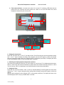
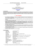
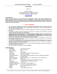
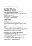
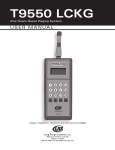
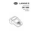
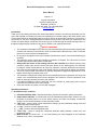
Doccol PID Temperature Controller*
Model WS1500B
User’s Manual
Version 1.0
Doccol Corporation
1235 E Pennsylvania Ave
Redlands, CA 92374
Tel: (888) 481-0842; Fax: (888) 893-5285
www.doccol.com
July 2008
Introduction
Thank you for purchasing the Doccol WS series temperature controller. We sincerely appreciate your decision and trust that our machine will meet your expectations in both the quality of the result and the value
of our product. While we are delighted that you may be anxious to operate the controller for your project, a
few minutes of your time reading through this manual will only serve to enhance your experience in the
months and years ahead. In particular, we would urge you to read through the safety warnings below. Although this plug-and-play controller is very easy to operate, your safety is paramount.
SAFETY WARNINGS
•
•
•
•
•
•
•
•
This controller was designed to be used only with selected heating devices that have limited power
and their own thermal cut off protection, such as a thermostat or thermal fuse in case of controller
failure. Do not use it with an untested device.
Do not place any objects on the top of controller surface that is used to vent excess heat during its
operation.
The maximum electric current this controller can handle is 15 ampere. For 120-volt AC in US and
Canada, this limits the heater power to1800 watts.
Always affix the sensor on the heating pad when the controller is on. Before turning on the
controller, please make sure the sensor has been placed on the heating pad to be controlled.
Leaving the sensor outside will form an open loop operation; controller will assume the temperature is low and will provide full power to the heater even if the heating pad is already over-heated.
The power cord provided with controller is specially designed for high power applications. Do not
replace it with regular computer power cord.
This controller is designed to control devices recommended by Doccol Corporation only. Using it to
control a not recommended device can be dangerous and cause fire. Doccol Corporation is not
liable for damages caused by misuse of the controller.
If an abnormal display or noise is observed, turn the controller off, unplug the power cord and
contact the manufacturer before using it again.
Clean the controller only when it is cool and unplugged.
Operating Instructions
1. Description of the controller.
1) Parameter Window (LED) - displays temperature values and controller's system parameters.
2) Output status indicator - In normal mode, this LED indicates the heater status. When it is on (lit),
the heater is powered. When it is off, the heater power is off. When it is flashing, it means the
heater is on and off intermittently to reduce the power output.
3) “SET” Key – press to show current temperature settings, get into parameters setting mode and
confirming various actions taken.
4) “+” Key – press to increase displayed value.
5) “_” Key – press to decrease displayed value.
6) “Time” Key – press to change the Parameter Window’s display between current timer and
temperature values.
7) Mode indicator, the small “dot” – if it is lit and flashing, the value displayed in the Parameter
Window is time, else it is temperature.
1
* Patent pending
Doccol PID Temperature Controller*
Model WS1500B
8) Timer status indicator- In normal mode, when “8)” is on and “7)” is flashing, LED shows the time
passed since the controller has been powered on. When it is off, the LED shows the current
temperature detected by the sensor probe.
1
2
8
7
3
5
4
6
Fig 1. Front panel
Connect to
temperature
sensor
Power switch
Connect to
electricity
Connect to
heating pad
Fig 2. Back panel
2. Setting the temperature.
Press SET key twice, both “2)” and “7)” will start to flash. The LED shows the current temperature setting.
Use “+” and “-“ keys to change the setting. When finished, press the SET again to confirm the change.
Note: the temperature setting will not be changed if SET is not pressed (confirmed). The display will return
to the normal display mode if no key is pressed within 3 seconds.
3. Switching the display between temperature and time.
This is done by pressing the Time Key (“6)”) once. When “8)” is on (lit) and “7)” is flashing at the same time,
LED is in timer mode and shows the actual time passed since the controller was last powered on. When
“8)” is off (not lit), LED is in temperature mode and shows the current sensor temperature.
4. Setting the timer.
Press SET key once and release it, both “7)” and “8)” will start flashing. The LED shows the current timer
setting. Use “+” and “-“ keys to change the timer setting. When finished, press the SET again to confirm the
change.
Note: the timer setting will not be changed if SET is not pressed (confirmed). The display will return to the
normal display mode if no key is pressed within 3 seconds.
2
* Patent pending
Doccol PID Temperature Controller*
Model WS1500B
5. Using the timer
The timer can be used in two different ways.
a) Use it as timer. If you set the timer for 20 hours, the controller will stop sending power to the heater 20
hours after it is powered up. It will display “End” on the window and send an audio beeping sound.
Turning off the power and on again will reset the timer.
6. Tuning the controller
This controller is shipped with parameters set for in vivo small animal surgery, temperature set at 35 °C.
The only thing that you need to do is to set your desired surface temperature for the heating pad.
6.1 Auto-Tune
The controller's most powerful feature is its ability to regulate virtually any heater with stable temperature
control. For stable temperature control the controller requires two things; (1) the controller must be set to
the correct power level (see next section) and, (2) that it must be tuned to the heater being used. Tuning is
the process that matches the control characteristics of the controller to the heating characteristics of the
heater. The controller is said to be tuned to the heater when its memory is programmed with values telling
it how fast the heater warms up, cools off, and how efficiently it transfers heat. Describing how fast the
heater heats when electricity is turned on and how fast it begins to cool when it's turned off. These time
constants are called the tuning parameters.
.
Every type of heater has its own unique set of tuning parameters. For the controller to heat with stability, it
must have programmed with the tuning parameters for the heater currently being used.
When Should the Controller be tuned?
The controller is pre-tuned to work with our heating pad. You may use the auto-tuning function to let the
controller to determine the PID parameters for other heaters automatically. Auto-tuning function (it’s often
known as self-tuning) can automatically optimize the PID parameters for your chosen heating system. The
auto-tuning function will heat up your heater then let it cool down. It will repeat this heat/cool cycle several
times. Based on the response time of the whole heating system, the controller will calculate and set the
PID parameters for your heater.
Before using the auto-tune function, you must set the heating equipment up in the exact configuration it
should be used. If the heater has its own thermostat or power control, turn both as high as they’ll go. Set
the controller to the appropriate power level (see next Section). Turn the controller and heater on, and then
enter the desired set point temperature closed to your
normal heating temperature.
To activate auto-tuning, just enter code 166 to get into
the PID setting menu. Set AΓ to 1 then exit the menu
(see Fig 3). The display will start to flash alternately
between AΓ and the current water bath temperature,
which indicates auto-tuning is in progress. When the
display stops flashing, the auto-tuning is finished. Now,
the newly calculated PID parameters are set and are
used for the system. The new parameters will store in
the memory even the power is off.
You should always write down your old PID parameters,
before letting the controller to perform auto-tuning. The
P, I, and D parameters have been pre-set to 45, 200,
and 250, respectively. This way if something goes
wrong, you can always go back to your old PID parameters. Basically, you must setup your heating system
close to your actual heating environment.
3
* Patent pending
Fig 3. Code 166 parameter setup flow chart
Doccol PID Temperature Controller*
Model WS1500B
The duration of auto-tuning depends on how fast the system is responding to the heating and cooling cycle.
If the temperature of the heater takes a long time to drop when heater is off, the auto-tuning could be a
very long tuning process. This is especially true with a well-insulated heater. The auto-tuning should be
able to tune most of your chosen with fairly good result.
6.2 Manual Setting the PID parameter.
If you have tried auto-tune and the parameters we provided but feel the performance is not ideal, the following sections discuss the definition of these parameters and how to change them.
•
•
•
•
•
•
•
•
•
•
•
•
LCK. Parameter lock. This function is used to prevent user to change the critical parameters by
accident. User has to enter the code 166 to access the parameter setting menu (Fig 3).
P. Proportional band. It is in 0.1 degree unit. This parameter control the output of the controller
based on the difference between the measured and set temperature. Larger the P number means
the weaker the action (lower gain). When the sensor temperature is 10 degrees below the proportional band (10 degrees below the setting), the controller will have 100% output. When the temperature is 5 degree below the set point, the output is 50%. When the temperature is equal to the
setting, the controller will have 0% output (assuming integral and derivative functions are turned
off). This constant also affects both integral and derivative action. Smaller P values will make the
both integral and derivative action stronger. Please note the value of the P is temperature unit
sensitive. If you found an optimized P value when operating the controller in Celsius, you need to
multiply the P by 1.8 when changing the temperature unit to Fahrenheit.
I. Integral time. The unit is in second. This parameter controls the output of controller based on the
difference between the measured and set temperature integrated with time. Integral action is used
to eliminate temperature offset. Larger number means slower action. When temperature fluctuates
regularly (system oscillating), increase the integral time. Decrease it if the controller is taking too
long to eliminate the temperature offset. When I=0, the system becomes a PD controller.
d. Derivative time. The unit is in second. Derivative action contributes the output power based on
the rate of temperature change. Derivative action can be used to minimize the temperature overshoot by responding its rate of change. The larger the number is, the faster the action will be. The
derivative action change the controller output based on the rate of change rather than the net
amount of change. This will allow the controller to act sooner. It will turn the heater to full power
before the temperature drops too much
T, cycle rate. The unit is in second. This unit determines how long for the controller to calculate
each action. This parameter should remain at 2 second for almost all applications.
Press and hold SET key for 4 seconds until LED display “LCK”, then release the SET key. The
display will show “0”. To get into parameters setting mode, you need to key in the pass code. Use
“+” and “-“keys to adjust the display to 166 (which is the pass code) and press SET.
The LED will show “P” for a second and then its P setting value, Use “+” and “-“ keys to change the
setting. When finished, press the SET again to confirm the change.
The display will show the “I “ for a second and its I setting value next, use the same “P” setting
procedure to set the I value. When finished, press the SET again to confirm the change.
The display will show the “d” for a second and its value next. Use the same “P” setting procedure
to set the d value. When finished, press the SET again to confirm the change.
The next setting is AΓ, the auto-tune. Use “+” to set the value to 1 and press SET will activate the
auto-tune.
The next setting is the “t” setting, use “-” and “+” to set the cycle time value. This value should
remain 2 for most application.
After change the PID parameter, the controller needs to be turned off and on again for the best
result.
7. Setting other system parameters
4
* Patent pending
Doccol PID Temperature Controller*
Model WS1500B
These are the parameters that normally do not need to be
changed. The lock code to access them is 155 (Fig 4).
Description of parameters:
• SC, calibration offset. The parameter is used to
make the input offset to compensate the error
produced by sensor. For example, if the temperature displays 2.0 C in ice water mixture, set
SC=-2.0 will make the display to shown 0.0 degree.
• OUt, Output power reduction. It is expressed as
a percentage value. This function will allow you to
control the maximum output power delivered by
the heater, for example, if you set OUt=50 and
your heater is 1000 watts, the output will use 50%
of the 1000 watts as the full output. It reduces the
Fig 4. Code 155 parameter setup flow chart
1000W heater to a 500W heater. When the PID
algorithm determines 50% output value, the actual power output will be 250 watts.
• Please note that when the OUt is reduced to less than 30%, you should increase the cycle rate
(T) to give enough output resolution. The smallest amount of power the controller can output is a
half wave of the AC sine wave (because the zero voltage cross switching). For 60 Hz AC, 2
seconds cycle rate provides 240 half waves for the controller to divide. But when the OUt is
reduced to 30%, there is only 80 parts of half wave to divide. Increase the cycle rate to 6 second
will increase the output resolution to 240 parts.
• C-F, Display unit setting. This model can only be set to display the temperature unit in Celsius.
• TK, Timer setting. The timer function can be turned off by user.
Setting these parameters:
• Press and hold SET key for 4 seconds until Parameter Window displayed “LCK”. Release the
SET. The display will show “0”. Use “+” and “-“ keys to adjust the display to 155 (another pass
code) and press SET.
• Setting the calibration offset. The parameter window will first show “SC “for a second and then
its value, Use “+” and “-“ keys to change the setting. When finished, press the SET again to confirm the change. For example, if the temperature is 1 °C higher than it should be during calibration,
then use “-” to set the value to -1 to offset value.
• Setting the output reduction. The parameter window first will show “OUt “for a second followed
its value. Use “+” and “-“ keys to change OUt value to your desired limit value and press SET.
• Setting Celsius (C) or Fahrenheit (F). This model can only be set for Celsius.
• Turning Timer “OFF” or “ON”. When SET is pressed, the display will show “ry” and then “1” or
“0”. Press “-” for “0” (off) and “+” for “1” (on). Press SET will return to Normal mode.
Summary: Parameters and initial settings.
Symbol
Description
Range
Initial
P
Display
p
Proportional band (in 0.1 degree)
0-600
45
I
I
Integral constant (second)
0-900
200
d
d
A
Derivative constant (second)
0-300
250
Auto-tune
0=off 1=on
0
Cycle rate (second)
1-100
2
Off set (degree)
-20~+20
0
Output power reduction (%)
1-100
100
AT
Τ
SC
SC
Out
C-F
Temperature unit
°C or °F
°C
ΤΚ
Timer,
1=on, 0=off
1
SV
Set temperature
0-99.9°C,
37.0
Timer
Timer (hour)
0-99.9
99.9
C-F
5
* Patent pending
Doccol PID Temperature Controller*
Model WS1500B
8. Warranty
Doccol Corporation warrants this controller to be free from defects in materials and workmanship for a
period of one (1) year from the date of the original purchase when the device is utilized under normal
condition. The sensor of the controller is warranted for 90 days. This warranty is subject to the following
conditions:
If the appliance is found to be defective in material or workmanship by Doccol Corporation, we will repair or
replace it free of charge. A dated proof of purchase may be required.
Doccol Corporation’s liability is limited solely to the cost of the repair or replacement of the unit at our discretion. This warranty does not cover normal wear of parts and does not apply to any unit that has been
tampered with or used for commercial purposes. This limited warranty does not cover damage caused by
misuse, abuse, negligent handling or damage due to faulty packaging or mishandling in transit. This warranty does not cover damage or defects caused by or resulting from damages from shipping or repairs,
service or alterations to the product or any of its parts which have been performed by a repairperson or
facility not authorized by Doccol Corporation.
This warranty is available to the original purchaser of the unit and excludes all other legal and/or conventional warranties. The responsibility of Doccol Corporation, if any, is limited to the specific obligations expressly assumed by it under the terms of the limited warranty. In no event is Doccol Corporation liable for
incidental or consequential damages of any nature whatsoever. Some states/provinces do not permit the
exclusion or limitation of incidental or consequential damages and therefore the above may not apply to
you.
This warranty gives you specific legal rights and you may also have other rights that vary from state to
state or province to province.
*Important: Carefully pack item to avoid damage in shipping. Be sure to include proof of purchase date and
to attach a tag to item before packing with your name, complete address and phone number with a note
giving purchase information, model number and what you believe is the problem with the item. We recommend you insure the package (as damage in shipping is not covered by your warranty). Mark the outside of your package “ATTENTION CUSTOMER SERVICE”. We are constantly striving to improve our
products and therefore the specifications contained herein are subject to change without notice.
6
* Patent pending