1
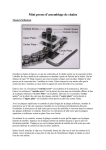
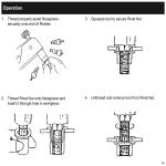
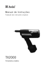
1206 East MacArthur Street, Sonoma, CA 95476
Phone: (707) 935-1170 ● Fax: (707) 935-1828
Web: www.fsirivet.com ● Email: [email protected]
D-9000-MIL-2
NSN: 5180-01-470-6539
Operations Manual
D-9000-MIL-2 BLIND FASTENER INSTALLATION TOOL KIT
(Kit contains 86 separate pieces inside its carrying case.)
®
D-9000-MIL-2
BLIND FASTENER INSTALLATION TOOL KIT
NSN 5180-01-470-6539
KIT CONTENTS
QTY
PART NUMBER
DESCRIPTION
1 EA
1 EA
1 EA
1 EA
1 EA
2 EA
1 EA
1 EA
4 EA
1 EA
1 EA
1 EA
1 EA
1 EA
1 EA
1 EA
1 EA
1 EA
1 EA
1 EA
1 EA
1 EA
1 EA
1 EA
1 EA
1 EA
1 EA
1 EA
1 EA
1 EA
1 EA
D-700-VM
PT-100M
PT-4000
D-28
F-4000A
F-3001A
F156
F159
F143
F142
F168
F169
F580
F396
F398
F155
F390
F391
F392
F393
F501
F502
F503
F505U
F506
F360
F367
F361
F364
F372
F176
HAND HYDRAULIC RIVETER, PRESSURE VALVE
AIR HYDRAULIC RIVETER
CORDLESS RIVETER
HAND RIVETER
BATTERY CHARGER, SMART
BATTERY PACK, Ni-MH (12v, 3.2AH)
3/32-1/8 NOSEPIECE
1/8 NOSEPIECE
1/8-3/16 NOSEPIECE
1/4 NOSEPIECE
3/16 MONOBOLT NOSEPIECE
1/4 MONOBOLT NOSEPIECE
3/16 MS NOSEPIECE
3/16 BULBTITE NOSEPIECE
1/4 BULBTITE NOSEPIECE
1/4 “T” RIVET NOSEPIECE
3/32 NAS 1400A NOSEPIECE
1/8 NAS 1400A NOSEPIECE
5/32 NAS 1400A NOSEPIECE
3/16 NAS 1400A NOSEPIECE
1/8 NAS 1900S NOSEPIECE
5/32 NAS 1900S NOSEPIECE
3/16 NAS 1900S NOSEPIECE
5/32 MS90353/54-S/U NOSEPIECE
3/16 MS90353/54-S/U NOSEPIECE
6-32 PULL-UP STUD
NO. 6 ANVIL
8-32 PULL-UP STUD
NO. 8 ANVIL
10-24 PULL-UP STUD
NO. 10 TSN ANVIL
SUPPLIER CAGE CODE: 64878
FASTENING SYSTEMS INTERNATIONAL, INC
SONOMA, CA 95476
1 OF 2 PAGES
PAGE 2
D-9000-MIL-2 KIT CONTENTS
1 EA
1 EA
1 EA
1 EA
1 EA
1 EA
1 EA
2 EA
1 EA
1 EA
1 EA
1 EA
1 EA
1 EA
1 EA
1 EA
1 EA
1 EA
1 EA
1 EA
1 EA
1 EA
1 EA
1 EA
1 EA
1 EA
1 EA
1 EA
1 EA
3 EA
1 EA
3 EA
3 EA
1 EA
1 EA
1 EA
1 EA
2 EA
1 EA
2 EA
1 EA
1 EA
1 EA
1 EA
1 EA
1 EA
F362
F365
F373
F177
F363
F366
F374
F378
F377
F375
F379
F384
F365M
F380
F366M
F368
F378M
F387
F379M
F170-A
F171
F187-3BCM
F187-3ACM
F187-1AR
F687-1AF
F687-2A
F1074
F1075
F1076
F702
F128
F122-A
F123
F123-A
F123-B
F758
F958
F990
F3245
F3081-A
F101
F269C3
F609A
F701-D9
F754-D9000
F755-D9000
SUPPLIER CAGE CODE: 64878
FASTENING SYSTEMS INTERNATIONAL, INC.
1206 EAST MACARTHUR STREET
SONOMA, CA 95476-1372
10-32 PULL-UP STUD
NO. 10 ANVIL
1/4-20 PULL-UP STUD
NO. 1/4 TSN ANVIL
1/4-28 PULL-UP STUD
NO. 1/4 ANVIL
5/16-18 PULL-UP STUD
NO. 5/16 ANVIL
5/16-24 PULL-UP STUD
3/8-16 PULL-UP STUD
3/8 ANVIL
5 MM PULL-UP STUD
5 MM ANVIL
6 MM PULL-UP STUD
6 MM ANVIL
8 MM PULL-UP STUD
8 MM ANVIL
10 MM PULL-UP STUD
10 MM ANVIL
MASTERSHAFT
TURN NUT
ADAPTER SHAFT, COMPENSATING
ADAPTER SHAFT, THROUGH HOLE
ADAPTER SLEEVE, ROTATING
ADAPTER SLEEVE, FLATS
ADAPTER SHAFT, MS STYLE
EXT STR PULLING HD
RIGHT ANGLE PULLING HD
OFFSET PULLING HD
SPARE PARTS CANISTER
BLIND BOLT JAW HOLDER
2 PIECE CAST JAW SET
3 PIECE CAST JAW SET
3 PIECE JAW SET/ BB 5/32
3 PIECE JAW SET/ BB 3/16
JAW PUSHER BB, D-700
JAW PUSHER. PT-100
JAW PUSHER SPRING, PT-100
1/4 JAW FOLLOWER
JAW PUSHER SPRING
RIVET NUT STROKE GAGE
RIVET GRIP GAGE
METAL WEATHER TIGHT CASE
CD-ROM, USER MANUAL
OPERATING INSTRUCTIONS
LAMINATED TOOL ASSY CARDS
ATTENTION TECHNICIANS
The D-9000-MIL-2 Blind Rivet Tool Kit is supplied with
four riveters with 3/16” diameter nosepieces installed in
their nose assemblies. The D-28 Hand Riveter comes
with 2 piece jaws. All other riveters come with 3 piece
jaws (F123) which permit installation of most all rivets
from 1/8” thru 1/4” simply by changing the nosepiece,
EXCEPT, in the case of the PT-4000 Cordless Riveter,
which requires a larger jaw follower (P/N F3245) for
1/4” diameter rivets. Except for the D-28 Hand Riveter,
which comes with 2 piece jaws, the riveters all will
require the use of 2 piece jaws (F122-A) for 3/32”
diameter rivet installation. The 2 piece jaws (F122-A)
are furnished in the spare parts canister (F701).
Common blind fasteners used throughout the U.S.
military branches have been provided in a convenient
chart form to help identify the proper nose assembly.
For information on any other blind riveting applications
for ground and aircraft/aerospace vehicles, please contact us at toll free 1-800-344-2393 or email us at
[email protected].
USER GUIDE
BLIND RIVET GRIP GAGE (F269C3)
BLIND RIVET GRIP GAGE
The Blind Rivet Grip Gage, F269C3, has been provided to permit the technician to properly
select the rivet grip length required for the materials being joined. Blind rivets are normally specified
by their diameter (in 1/32 “ increments) and their grip (in 1/16” increments); hence, a 3/16” diameter
blind rivet with a 1/4 “ grip would have a suffix of -06-04 after the basic rivet manufacturer’s part
number or military specification number (i.e. CR3213-06-04 nominal diameter CherryMax. The
numbers are often abbreviated to -6-4).
You will notice that the grip gage has several holes in it. They are to enable the rivet user to
distinguish between the oversize (1/64”) and nominal diameter sizes. Once the sheets to be joined are
brought tightly together a hole is then drilled and the grip gage can be inserted into the hole. The hook
end of the gage should then catch on the back side of the hole and then the slide bar is brought down
until it touches the top sheet. The gage can then be removed and the grip measured. Notice that the
gage is scaled in 1/16” increments.
Most commercial and aerospace blind rivets have at least a 1/16” grip range with the dash
number signifying the maximum thickness or “grip range” that the rivet may be used in. If the measurement falls right on the line, then the user, in the case of aerospace quality blind rivets, can elect to use
either the maximum grip of one rivet or the minimum grip of a longer rivet (i.e. a .250” reading would
allow the use of either a -4 grip rivet in its maximum grip or a -5 grip rivet in its minimum grip). In
normal circumstances users, if they have the option, will more likely select the rivet used in its maximum grip. This helps minimize blind side protrusion, and helps reduce unnecessary weight. Several
thousand rivets can add up to many extra pounds of weight the plane will have to carry over its lifetime
which of course translates into fuel consumption.
CAUTION
When gauging the material thickness it is always good to check at least two or more points
around the hole. This helps reduce the chance that a burr on the blind side is inadvertently hooked that
could give you a false reading. Of course any significant burrs or metal chips should be removed from
between the sheets before measuring.
F391
1/8 NAS1400A
Nosepiece
F502
5/32 NAS1900S
Nosepiece
F505U
5/32 MS90353/54 S/U
Nosepiece
F503
3/16 NAS1900S
Nosepiece
F155
1/4 T-Rivet
Nosepiece
F506
3/16 MS90353/54 S/U
Nosepiece
F398
1/4 Bulbtite
Nosepiece
F396
3/16 Bulbtite
Nosepiece
F169
1/4 Monobolt
Nosepiece
F168
3/16 Monobolt
Nosepiece
F501
1/8 NAS1900S
Nosepiece
F393
3/16 NAS1400A
Nosepiece
F392
5/32
NAS1400A
Nosepiece
F156
3/32-1/8
Nosepiece
F142
1/4 Nosepiece
F143
1/8-3/16
Nosepiece
F390
3/32 NAS1400A
Nosepiece
F159
1/8 Nosepiece
F580
3/16 MS
Nosepiece
D-9000-MIL-2 NOSEPIECE BAR
F384 5mm Stud
F365 Anvil
F386 8mm Stud
F378 Anvil
F380 6mm Stud
F366 Anvil
F387 10mm Stud
F379 Anvil
F101
Stroke Gage
F362 10-32 Stud
F365 Anvil
F363 1/4-28 Stud
F366 Anvil
F377 5/16-24 Stud
F378 Anvil
F374 5/16-18 Stud
F378 Anvil
F375 3/8-16 Stud
F373 1/4-20 Stud
F379 Anvil
F177 Anvil
F372 10-24 Stud
F176 Anvil
F360 6-32 Stud
F367 Anvil
F361 8-32 Stud
F364 Anvil
D-9000-MIL-2 Pull-up Studs/Anvils
AR
AR
AR
AR
AR
AR
AR
AR
AR
AR
D-700C Standard Blind Riveting Set-Up
F130-700C
Nose Tube
F122-A 2pc
Jaws
F126-F
Jaw Holder
F1381 Spring
F700-041
Jaw Follower
F188A
Adapter Bushing
CHART A
D-700C Set-up for Blind Nut Installation
F130-700C
Nose Tube
Anvil & Stud
F171 Turn Nut
F170-A
Master Shaft
F188A
Adapter Bushing
See Anvil & Studs
Table for part numbers
ATTENTION
Female side of turn nut
must face forward
CHART B
D-700C Standard Set-Up for NAS1400A
F130-700C
Nose Tube
F122-A 2pc
Jaws
F126-F
Jaw Holder
F1381 Spring
F700-041
Jaw Follower
F393
3/16”
F392
5/32”
F391
1/8”
F188A
Adapter Bushing
F390
3/32”
CHART C
D-700C Standard Set-Up for MS90353/54 S&U &
Washer Anvil Driven, Single Action Only
F505U = 5/32”
F506 = 3/16”
F130-700C
Nose Tube
F128
Jaw Holder
F700-041
Jaw Follower
F123-A = 5/32BB Jaws
F123-B = 3/16BB Jaws
F3181 Spring & F188A
Adapter Bushing
CHART D
D-700C Standard Set-Up for NAS1900S Type, Single Action
F130-700C
Nose Tube
F122-A 2pc
Jaws
F126-F
Jaw Holder
F503
3/16”
F1381 Spring
F700-041
Jaw Follower
F502
5/32”
F188A
Adapter Bushing
F501
1/8”
CHART E
D-700C Set-up for CherryMax® & Huck-Clinch (NAS9300/M7885 Pulling Heads
F187-1AR Adapter Sleeve &
F187-2A Puller Shaft
F1076 Offset Pulling Head
F1075 Right Angle Pulling Head
F1074 Extended Straight Pulling Head
CHART F
D-700C Set-up for MS & NAS1400A Pulling Heads
F687-1AR Adapter Sleeve &
F687-2A Puller Shaft
RV872 Offset Pulling Head
F1060 Side-Ejection Straight Pulling Head
RV882 Series Right Angle Pulling Head
CHART G
D-700C Set-up for Using the Stroke Gage
PT-4000
Operating Instructions
MKT-04 1/08
PT-4000 Rivet Capacity
The PT-4000 pulls most all pull style blind rivets including CherryMax and Cherry “A” Max
thru 1/4” diameter in all materials and Blind Bolts and Maxibolts thru 3/16” diameter.
Equipment/Accessories
Nosepieces:
3/32 thru 1/4
Wrench:
SW 12 (covers nosepiece compartment
Suspension Loop:
Flips open from housing
Battery:
Quick Charge/ 12 Volt DC
Technical Data
Weight:
4.85 lbs (with battery)
Stroke:
787”
Drive Unit:
12 V direct current motor
Traction Power: 3,000 lbs.
Nosepiece
Table:
Rivets Per Battery
Charge
Rivet Dia.
Rivet Body Material
*Rivets Per Charge
Nosepiece Part No.
3/32” Aluminum
1,900
F140
1/8” Aluminum
1,300
F159
1/8” Steel
1,100
F159
1/8” Stainless Steel
1,000
F159
1,000
F143
5/32” Steel
900
F143
5/32” Stainless Steel
800
F143
3/16” Aluminum
700
F143
3/16” Steel
500
F143
3/16” Stainless Steel
400
F143
1/4” Stainless Steel
90
F142
5/32” Aluminum
* Rivets per battery charge based on Mil-R-24243 style blind rivets in maximum grip condition
Starting Procedure
Install fully charged battery into housing. Select proper nosepiece (see page 2) and screw into
head.
Attention: Do not cover or stick anything into the vent holes.
Operating Procedure
Pushing the trigger starts the operation. When releasing the trigger, the jaw mechanism returns to
the start position automatically.
Eject the spent mandrel into the mandrel container by tilting the tool backward, or through the
nosepiece by tilting tool forward.
The riveting tool is equipped with overload protection. In case if an overload, the operation will
be stopped and the red light goes on. If that happens, release the trigger and the mechanism will
return to the start position.
The battery will deliver uniform power for tool operation until depleted to the last 2-3 rivets of
charge capacity. It is designed to have the jaw mechanism return to the starting position when the
trigger has been released.
Maintenance
The maintenance of the riveting tool is limited to the complete jaw mechanism and the included
wearing parts.
Remove the battery (#40) from the tool housing. Unscrew the head (#13) from the tool and clean
it. Unscrew the jaw housing (#12) from the coupler. Take out the jaws (#11), clean and lubricate
or replace if worn. Reassemble in reverse order and make sure that all parts are tightened!
Warranty
There is a 6 month warranty from the day of delivery on the PT-4000. Damages caused by common wearing, overloading or improper usage or handling are excluded from the warranty. Damages caused by material or manufacturing faults will be covered by this warranty and will be repaired or replaced at no cost. Claims can only be accepted if the complete riveting tool, fully assembled, is returned to the distributor or FSI.
Battery / Charger
Technical Data
Charger
Battery
Input Voltage:
110 V/60 Hz
Rated Voltage:
12 VDC
Output Voltage:
12 VDC
Number of Cells:
10 Pieces
Recharge Time:
Approx. 1 hour
Cell Construction:
Nicad with
Weights:
2.6 lbs.
Overcharge protection
Capacity:
1.4 amp hour
Weight:
1.4 lbs
Recharging Procedure
Take charger out of steel case and connect to power line.
Make sure the voltage is in accordance with the label!
The battery must be installed correctly (positive pole to positive pole) with minimal force into
the charger. The quick recharging procedure is automatically started and indicated by red light.
After approximately 1 hour the charging procedure is finished and the charger switches to
trickle charge, indicate by a green light.
Place only cool batteries into the charger in order to obtain a full battery recharge.
Battery Handling
The battery is rechargeable up to 1000 times and reaches its full power only after several rechargings. Do not discharge the battery completely. Recharge is not used for an extended period.
Substantially reduced operating time of battery after a proper recharge indicates the battery
must be replaced. Keep battery in a cool and dry place, with temperature not to exceed (122 F).
Environmental Protection
If batteries have to be replaced, the following instructions should be followed:
Return used batteries to your supplier or FSI for recycling. Under no circumstances should
nickel-cadmium batteries be discarded as normal waste which might be burned or exposed to
ground water.
Trouble Shooting
Blind Rivet Cannot be Set
Causes
Remedy
Depleted battery charge
Recharge, if necessary replace
Jaws dirty or worn
Clean and lubricate or replace
Jaw pusher spring weak
Tighten
When trigger is pressed, no function
Replace
(red indicator light shows)
No Spent Mandrel Discharge
Causes
Remedy
Wrong nosepiece
Exchange according to page 2
Nosepiece worn
Replace
Mandrel jammed in jaws
Loosen the mandrel, clean and lubricate the
jaws or replace
Head Dirty inside
Clean
Spent mandrel container filled
Remove and empty
Passage clogged
Remove clogged mandrels and check for free
ejection
Red Light Indicated Faults
A) When trigger is pressed
Causes
Remedy
Overheating of electronic control
Allow too to cool to ambient temperature
B) While pulling the rivet
Causes
Remedy
Overloading
Check working capacity
Overheating of electronic control
Allow tool to cool to ambient temperature
Depleted battery charge
Recharge or replace
C) After releasing the trigger
Causes
Remedy
Jaw mechanism is not reaching the front
Tighten jaw mechanism
position
Maintenance Instructions
General Notes
Warranty repairs are carried out by the manufacturer only. Repairs outside the warranty period
should only be carried out by trained personnel. The following instructions must be strictly adhered to, as assembly or adjustment errors may cause major damage to the PT-4000.
Repair Tools & Lubricant
For repair of the PT-4000, the following should be available:
Screw Driver Torx T 20
Hexagonal Wrench SW 2.5 mm
Open End Wrench 27 mm
Open End Wrench 17 mm
Open End Wrench 14 mm
Lubricating Grease (#46)
Dismantling the PT-4000
Remove battery (#40) from the tool. Unscrew spent mandrel container (#39). Remove housing
screw (3 pcs. #32 & 5 pcs. of #33) with screw driver Torx T 20.
Take off hand guard (#31). Take off top of tool housing (#1) and pull off the red and blue connecting wires from the electronic control (#26). Unscrew electronic control (#26) using screw
driver Torx T 20.
Unscrew magnet holder (#27) using the hexagonal wrench SW 2.5mm. Take out electronic
control (#26) and magnet holder (#27). Take out motor (#25).
ATTENTION: Reassembly Tip: Note how connecting wires to the motor are laid out in
the tool housing!
Take out drive system (#42). Unscrew head (#13) using open end wrench SW 27mm. Unscrew jaw housing (#12) using open end wrench SW 17mm and take out jaws (#11), jaw pusher
(#10) and jaw pusher spring (#9).
Unscrew jaw housing coupler (#7) with scraper ring (#8) using open end wrench SW 14mm.
Remove screws (4 of #6) using hexagonal wrench SW 2.5mm. Pull off drive bearing (#3) and
pinion shaft (#4) with snap ring (#6) and bushing (#20).
Assembly & Stroke Adjustment
Assembly of Drive System (#42) Slip drive bearing (#3) over ball screw drive (#2) and put pinion shaft (#4) together with snap ring (#5) in bearing place.
Attention: Before screwing ball screw drive (#2) and drive bearing (#3) together, make sure the
locating marking “B” of the bearing disk inside the ball screw drive (#2) is placed opposite the
pinion shaft (#4). See Parts Drawing.
Assemble this entire unit together with the 4 screws (#6) using hexagonal wrench SW 2.5mm.
Screw jaw housing coupler (#7) with scraper ring (#8) onto ball screw using open end wrench
SW 14mm.
Put jaw pusher spring (#9) and jaw pusher (#10) onto jaw housing coupler (#7). Place the jaws
(#11) in jaw housing (#12) and screw this onto jaw housing coupler (#7) using open end wrench
SW 17mm.
Screw head (#13) on using open end wrench SW 27mm.
Assembly of the PT-4000
The sub-assemblies and other parts should be put into tool housing half (#1) containing the
nosepiece bracket as follows:
To install drive system (#42), slip the bushing (#20) onto the shorter end of the pinion shaft (#4)
while ensuring that the snap ring (#5) in pressed to the gear.
To insert the tube (#22), the longer end of the tube must be inserted into the ball screw, while
the collar of the tube must be inserted into the provided recess of the tool housing.
To place the motor connecting wire, the red wire should be bent downwards at the soldering tag
towards the blue wire, then bent again to be parallel with the blue wire.
To install motor (#25), the two connecting wires are to be places side by aide around the first
guiding stud of the tool housing and behind the middle guiding studs. The wires should then be
brought up in front of the third guiding stud.
The electronic control unit (#26) should be installed by putting it on the stud inside the tool
housing and then fastened with the housing screw (#32). Click magnet holder (#27) in the guiding slot of the electronic control (#26).
Fasten other end of magnet holder (#27) to ball screw drive (#2) with magnet holder screws
(#28) together with two spring lock washers (#29) using the hexagonal screw drive SW 2.5.
For later stroke adjustment, do not tighten the screws. Plug the two blue connecting wires of
motor (#25) and electronic control until (#26) together.
DO NOT CONNECT RED WIRE YET!!
Stroke Adjustment
Turn gear of pinion shaft until distance “A” measures 0.118” -See Parts Drawing. Then insert
battery (#40) correctly in tool housing.
Attention: Positive pole of battery (#40) must be at top to avoid damage of electronic control unit (#26).
While trigger is pressed, magnet holder (#27) must be adjusted in slot of electronic control until
red indicator light goes on. After releasing trigger, the two magnet holder screws (#28) must be
tightened. NOW connect red wire to electronic control (#26).
Attention: Both connecting wires must be places around guiding stud on electronic control
(#26) in such a way to keep slot free for movement of magnet holder (#27).
Preliminary Motor Test: Motor (#25) is be carefully held down at both ends. Make sure to allow room for magnet holder to move back and forth. Pull trigger to move jaw mechanism
about .200 to .400 inches, and release trigger.
Check distance “A” (See Parts Drawing). It must be 0.039” - 0.051”
If distance “A” gap is below 0.039”, magnet holder (#27) should be moved carefully to the right
after loosening the to screws (#28) in order to obtain .039 to .051 gap.
If distance “A” gap is larger that 0.051”, magnet holder must be moved to the left accordingly.
After tightening the screws (#28), repeat test and recheck distance “A”. Take battery (#40) out
of toll housing.
Finishing
Lubricate gear teeth with lubricating grease (#46). Insert suspension loop (#30). Insert hand
guard (#31). Replace second half of tool housing.
Tighten both halves of tool housing (#1) together with the five housing screws (#33) and the
three housing screws (#32) using screw driver Torx T 20.
Safety Notes
The PT-4000 has been designed and manufactured in accordance with the applicable safety
regulations. If the PT-4000 is being used for the intended purpose in accordance with instructions and normal safety measures, there is no danger involved during operation.
WARNING! Never operate the PT-4000 without placing the blind rivet in proper hole of
the work piece or material. The rivet could be propelled from the tool. Avoid pointing the
tool at anyone during operation.
The spent mandrel container (#39) must always be firmly screwed into place on the tool during
operation. Do not plug or cover vent holes in tool housing an any time.
Repairs should be carried out by trained personnel only. Otherwise, return PT-4000 to supplier
or to FSI.
Do not operate the PT-4000 and the Battery Charger in an environment allowing exposure to
moisture, combustible fluids or gases.
Safety Notes: (continued)
Avoid damage to cord and plug of charger. Inspect regularly for any damage. Ensure that the
battery is properly secured in the tool housing.
Take the charger out of steel case when recharging the battery. Place the battery in the correct
position (+pole to +pole) and do not force it into the charger.
Always remove the battery before servicing / repairing the PT-4000.
Do not discard batteries into water or fire as danger of explosion exists. Any used battery be
disposed of in accordance with environmental regulations.
Do not use the PT-4000 for any function other than riveting, especially not as a hammer.
Safety Precautions
PT-4000 CORDLESS BLIND RIVETER
The PT-4000 Blind Riveter has been designed with safety in mind and it conforms to all applicable regulations governing cordless battery operated tooling. If utilized in accordance with
operating instructions, danger free application of the tool is assured.
CAUTION: Do not rivet without the rivet being installed into material. The rivet body
and a portion of the mandrel can shoot away from the tool which could cause injury.
Stem canister (Item #39) should always be mounted on the tool to catch spent stems.
The ventilation holes to the electric motor must not be obstructed. Do not cover or place anything over them.
Repairs should only be undertaken by skilled and trained repair technicians. If unsure, send
the tool back to your dealer or the factory.
The PT-4000 and the battery charger unit must be kept away from moist / wet surroundings
and away from flammable liquids and gases. Do not use in temperatures above 120 degrees F.
Socket, Plug and Charger unit should be routinely inspected, and if damaged, replaced or repaired.
To charge batteries, remove charger from steel case. The battery pack will only fit into
charger socket in proper orientation and is installable with a minimum amount of insertion
pressure.
When working on the PT-4000 (i.e., replacing jaws, jaw follower or spring) be sure the battery
pack is removed from the riveter.
Do not throw battery pack into water or fire as they can explode. The battery pack should be
recycled according to instruction manual.
Item
Part No.
1
F3014
2
Description
Item
Part No.
Tool Housing,
complete
22
F3761
Spent mandrel tube
F3189
Ball screw drive,
assembled
25
F3103
Motor, complete
3
F3185
Drive bearing,
complete
26
F3850
Electronic control
4
F3193
Power transfer
gear
27
F3266
Magnet holder, complete
5
F3753
Snap ring
28
F3990
Magnet holder screw
6
F3932
Screw
29
F3008
Spring lock washer
7
F3605
Draw Bolt
30
F3559
Suspension loop
8
F3745
Scraper ring
31
F3540
Hand guard
9*
F3081
Jaw pusher spring
32
F3032
Housing screw
10*
F3245
Jaw pusher, 1/4”
33
F3024
Housing screw, short
11*
F123
Jaws (3 pc)
35
F3030
Nosepiece bracket
12
F3126
Jaw housing
36
F3091
Nosepiece holder
13
F3130
Nosetube
37
F3834
Nosepiece wrench
14
F505
Nosepiece, 5/32”
Blind Bolt
39
F3282
Spent mandrel container
15
F506
Nosepiece, 3/16”
Blind Bolt
40
F-3001
Battery
16
F505-MB Nosepiece, 5/32”
Maxibolt
41
F3555
Lubricating grease
17
F506-MB Nosepiece, 3/16”
Maxibolt
42
F3197
Drive system (pos. 2-13,15)
F142
1/4” Nosepiece
18
F169
Nosepiece, 1/4”
Monobolt
43
19
F143
Nosepiece, 3/16
CherryMax
45
20
F3893
Bushing
Description
F-4000A Battery Charger
* Wearing Parts
PT-4000 (optional) Configurations
F130-F
Nose Tube
Standard
Configuration
F3621
Jaw Follower
F3605
Draw Bolt
Nosepiece
F126-F
Jaw Holder
CherryMax® Pulling
Head Configuration
Extended Straight
Pulling Head F1074
F3093
F3081
Spring
Spring
F123
3 pc Jaws
F187-1AF
Sleeve
Right Angle Pulling Head
F1075
F187-3BCM
Adjustable Adapter
Shaft
Offset Pulling Head
F1076
CherryMax® &
Pop® Rivets
Configuration
*Note: Replace Jaw Follower
F3621 with F3245 (see spare
parts canister) when installing 1/4” dia. rivets. You may
also use the F123 (3pc) jaws
for 1/8” thru 1/4” diameter
blind rivets.
*F3245
Jaw Follower
Rivet Types:
*
F122-A
2 pc Jaws
F3081
Spring
1/4” Rivets
F123-A or
F123-B
BB Jaws
MS90353/54 “U” &
“S” Type Blind Bolt
Configuration
F3081
Spring
Nosepiece
F130-F
Nose Tube
F128
BB Jaw Holder
F3245
Jaw Follower
Aerospace and Industrial Sheet Metal
●Applications●
Types of rivets installable
with the PT-4000 include,
but are not limited to, virtually all CherryMax®
(M7885), Avdel®, or
Cherry Monobolts®,
Cherry Interlock®, Huck
MagnaLok®, and Pop
type rivets. The PT-4000
is also capable of
installing both 5/32” and
3/16”
Blind
Bolts
(MS90353/54-S/U) with
the proper nosepieces
(provided in the Mil-1
and MIL-2 kits).
Pulling Head Assembly
Right Angle Pulling Head (F1075): Thread the internal threads of the pulling head’s draw bolt two
or three turns onto the adapter puller shaft. Next, engage the threads of the pulling head housing and
continue threading into place. To minimize stroke requirement and to set a particular rivet size, simply
adjust the nose tube of the right angle head by loosening the jam nut at its base.
Extended Straight (F1074): Thread the extended straight pulling head’s haw holder assembly onto
the adapter puller shaft assembly. (Tighten by putting rivet stem into adapter puller shaft hole to keep it
from rotating.) Next, take the straight pulling head’s jam nut and back it off at least ten full turns from
the end. Now thread the adapter sleeve into place, approximately six full turns. Use the red marker on
the jam nut to aid in counting. Next, engage battery pack into tool and fully retract the draw bolt / haw
holder assembly. While keeping the jaw holder fully retracted, insert desired rivet stem into nosepiece
(to set up for use with all sizes 3/16 oversize). Now allow the jaw holder assembly to come forward. If
it easily accommodates the stem (ie, you can move it in and out freely), you can now tighten the jam nut
into place. If, however, it does not readily accept or release the stem freely, begin turning the outer
sleeve clockwise in quarter turn increments until a proper setting is reached.
Offset Pulling Head (F1076): Thread the internal threads of the offset pulling head’s draw bolt onto
the male thread of the adapter puller shaft. Take two or three turns before engaging the male threads of
the pulling head housing. How thread both into place until there is no gap between the housing and the
draw bolt. Now tighten jam nut.
CAUTION: If you tighten the outer sleeve too far down, it will restrict the return of the draw bolt,
thereby causing an overload condition on the tool. The red indicator light will come on. Remove
the battery immediately, loosen outer sleeve, and restart assembly procedure. Failure to relieve
For Blind Bolt and Maxibolt Conversion
When pulling Blind Bolts and Maxibolts you will need to use the following items:
For 5/32 or 3/16 Blind Bolts and Maxibolts:
Remove Nose Tube (F130-F). Thread off Jaw Holder (F126-F) and Jaws (F122-A) and set aside. Be
careful not to allow the spring and jaw follower to come out of the tool. Next, you will need the Blind
Bolt Jaw Holder (F128). Insert Jaw Set (F123-A) 5/32 size into holder, keep rubber O-Ring securely
around the three piece jaws. This is important because you must keep the jaws aligned at all times while
pulling Blind Bolts or Maxibolts to prevent the stem from jamming and cracking the jaws. Thread Jaw
Holder (F128) onto the Draw Bolt (F3605) and thread nose tube back onto the tool. Then use the 5/32
Maxibolt Nosepiece (F505-MB) for S-Type Blind Bolts or the 5/32 Blind Bolt Nosepiece (F505) for
the U-Type Blind Bolts. Reverse the process to assemble tool for regular CherryMax riveting.
For 3/16 Blind Bolts and Maxibolts:
Remove Nose Tube (F130-F). Thread off Jaw Holder (F126-F) and Jaws (F122-A) and asset aside.
Be careful not to allow the spring and jaw follower to come out of the tool. Next, you will need the
Blind Bolt Jaw Holder (F128). Insert Jaw Set (F123-B) 3/16 size into holder, keep rubber O-Ring securely around three piece jaws. This is important because you must keep the jaws aligned at all times
while pulling Blind Bolts or Maxibolts to prevent the stem from jamming and cracking the jaws. Thread
Jaw Holder (F128) onto the Draw Bolt (3605) and thread nose tube back onto the tool. Then use the
5/32 Maxibolt nosepiece (F506-MB) for S-Type Blind Bolts or the 5/32 Blind Bolt Nosepiece (F506)
for the U-Type Blind Bolts. Reverse the process to assemble the tool for regular CherryMax riveting.
PT-100 / PT-100M Riveter
Operating Instructions
MKT-02
PT-100 SERIES RIVETER
NSN 5130-01-397-6805
ASSEMBLY DIAGRAM/OPERATING INSTRUCTIONS
Puller Shaft
Sleeve Spring
F124-A
Two Piece
Jaws
Nose Tube
F130
Nosepiece
Jaw Holder
F126
Reservoir Shield
Actuating Trigger
Releasing Trigger
Adapter Shaft
F187-2A
Adapter Sleeve
F187-1A
CAUTION: The PT-100 operates off 90 to 120 PSIG dry,
compressed air. Do not oil. Higher pressure may damage
the riveter.
Assembly Procedures:
1. Place the Two Piece Jaws (F122-A) inside the Jaw Holder (F126).
2. Place the assembled item into one end of Sleeve Spring (F124-A). The flange on
the Jaw Holder should bottom out on the Sleeve Spring. These two items fit together
firmly, thus some pressure may be required.
3. Next, point the tool downward, and place the open end of the Sleeve Spring (F124-A)
over the Puller Shaft and thread the Jaw Holder onto the Puller Shaft until it bottoms
out against Puller Shaft flange. (WARNING: FAILURE TO BOTTOM OUT
AGAINST THE FLANGE MAY DAMAGE THREAD AND/OR CAUSE RIVETS
TO JAM).
4. Place the Nose Tube (F130) over the complete assembly and hand tighten. Threads on
the outer sleeve should disappear and the Reservoir Shield should be stationary.
5. Now select the proper nosepieces for the diameter and type of rivet being used and
thread into the end of the Nose Tube until it bottoms out. It may be necessary to extend
the nose tube by actuating the trigger (see operating instructions) in order to thread the
nosepiece completely into place.
CAUTION: Nosepieces can loosen with use and may cause damage to
the threads if not kept tight. Check periodically, and if no other nosepieces are going to be needed for the day, tighten with a wrench.
PT-100 SERIES OPERATING INSTRUCTIONS
Actuating Trigger
Releasing Trigger
1. Connect PT-100 riveter to air source. Be sure to utilize clean, dry compressed air over a 90 to
120 PSIG range. If using a multi-plane swivel be sure swivel is properly tightened into tool before installing air fitting into swivel.
2. Select the proper nosepiece for installing the blind rivet being used and hand tighten it into the
nose tube. If frequent changing of the nosepiece is not required, slight tightening with a wrench
is recommended in order to prevent the nosepiece from backing out during riveting operation. If
rivet nosepiece will not easily install into nose tube simply actuate the Actuating Trigger and
cause the nose tube to move forward thus allowing ease of nosepiece installation.
3. Insert rivet into nosepiece being sure that the riveter is in the fully retracted position. (If nose
tube is partially extended, simply depress Releasing Trigger until the nose tube fully retracts to
starting position.) Place rivet into properly prepared hole and hold riveter against materials being
riveted using firm, steady pressure. Be sure to keep riveter as perpendicular to work surface as
possible (within +/- 1.5 degrees from centerline). Next, depress Actuating Trigger being careful
not to depress the Releasing Trigger at the same time. If you do, the tool will not actuate and the
hydraulic fluid (no. 10 machine oil) will just circulate through the by-pass valve. The riveter has
a maximum stroke of .625” and will set most blind fasteners in one stroke; however, if the tool
reaches the end of its stroke before setting a fastener: DO NOT CONTINUE TO DEPRESS
THE ACTUATING TRIGGER. Release the Actuating Trigger and depress the Releasing
Trigger. The riveter will then retract and you can re-grip the fastener and reactivate the tool until
you upset the fastener.
4. After the rivet stem breaks you may depress the Releasing Trigger, point the tool downward and
the broken rivet stem will drop out of the nosepiece. NOTE: If the rivet stem sticks in the nosepiece after the rivet is set, lightly tap the end of the rivet stem on a hard surface while holding the
Releasing Trigger in the full depressed position. This should then free the jaws and permit the
tool to release the rivet stem. If the rivet stem continues to bind or hang up in the nose assembly
check the jaw holder by removing the nose tube to see if it is properly tightened into place. If
loose, tighten and reassemble after checking the jaws to see that they are not severely worn. Replace if necessary.
NOTE OF CAUTION: If you cause the riveter to reach its maximum
stroke you may cause the riveter to go into a by pass mode which causes
a pressure relief valve to open (this occurs when approximately 4,400
lbs. of pulling force is reached). This condition will often cause the normal hand releasing pressure required to return the tool to its normal
position to increase. Simply increase pressure on the releasing trigger
and the tool will release.
F187 ADAPTER FOR SPECIAL PULLING HEADS INSTRUCTIONS:
1. Place the Adapter Shaft (F187-2A) into end of the Sleeve Spring (F124-A)
2. Place other end of the Sleeve Spring (F124-A) over the Puller Shaft and thread the
Adapter Shaft (F187-2A) onto the Puller Shaft hand tight against it so no threads are
showing.
3. Place the Adapter Sleeve (F187-1A) over assembly and hand tighten until threads disappear. Reverse for disassembly.
ASSEMBLY IS NOW READY FOR ANY OF THE SPECIAL PULLING HEADS.
Adapter
Shaft
F187-2A
Adapter Sleeve
F187-1A
Sleeve Spring
F124-A
Actuating Trigger
Right Angle Pulling
Head
F1075
Collet Assembly
729A25/701B29A
Offset Pulling Head
F1076
RIGHT ANGLE PULLING HEAD
ASSEMBLY INSTRUCTIONS:
Extended Straight Pulling Head
F1074
1. Thread interior draw bolt of the Right Angle Pulling Head (F1075) onto the
Adapter Shaft (F187-2A) 3 turns.
2. Push the Right Angle Pulling Head (F1075) into the Adapter Sleeve (F187-1A)
and mate thread. Thread at least 5 full turns until rivet stem fits easily into nose
piece (Adjust nose piece in for larger diameters.
3. Position head direction and set jamb nut. Reverse for disassembly.
4. Depress Actuating Trigger to install rivet (see operating instructions).
OFFSET PULLING HEAD ASSEMBLY INSTRUCTIONS:
1. Open Offset Pulling Head (F1076) 1/4” as shown.
2. Thread interior draw bolt of the Offset Pulling Head (F1076) onto the Adapter Shaft
(F187-2A) 4 turns.
3. Push the Offset Pulling Head (F1076) into the Adapter Sleeve (F187-1A) and mate
threads. Thread in until 1/4” head gap is fully closed. DON’T GO BEYOND!
4. Position head direction COUNTERCLOCKWISE ONLY. Set jamb nut.
5. Depress Actuating Trigger to install rivet. Rivet stems will push out the back. Reverse
for disassembly.
EXTENDED STRAIGHT PULLING HEAD ASSEMBLY INSTRUCTIONS:
1. Thread the Collet Assembly (749A25/701B29A) onto the Adapter Shaft (F187-2A)
2. Slide the Pulling Head Sleeve (F1074) over the Collet Assembly (749A25/701B29A) and
into the Adapter Sleeve (F187-1A) and mate threads. Thread on and bottom out against
assembly. DON’T GO BEYOND!
3. Set jamb nut. Reverse for disassembly.
4. Rivet may be forced in to open jaws initially.
5. Depress Actuating Trigger to install rivet.
ASSEMBLY DIAGRAM FOR OLYMPIC-LOK PULLING HEADS
- The Olympic-Lok (NAS1400 ‘A’ Code) and the Cherry-Lok use
the same non-shift tooling system
- One pulling head installs both flush and protruding head rivets
in all grips
- No tool adjustment required with this system
F687 ADAPTER FOR SPECIAL PULLING HEADS– INSTRUCTIONS
1. Place the Adapter Shaft (F687-2A) into the end of the Sleeve Spring (F124-A).
2. Place other end of the Sleeve Spring (F124-A) over the Puller Shaft and thread the Adapter
Shaft(F687-2A) onto the Puller Shaft hand tight against it.
3. Place the Adapter Sleeve (F687-1A) over assembly and hand tighten (threads should disappear). Reverse for disassembly.
ASSEMBLY IS NOW READY FOR ANY OF THE SPECIAL PULLING HEADS.
Adapter Shaft
F687-2A
Sleeve Spring
F124-A
Adapter Sleeve
F687-1A
Puller Shaft
Offset Pulling Head
RV872 or RV8872
Straight Extension Pulling Head
RV812
OFFSET PULLING HEAD ASSEMBLY INSTRUCTIONS:
1. Thread interior draw bolt of RV872 or RV8872 onto the Adapter Shaft (F687-2A)
approx. 4 turns.
2. Push RV872 or RV8872 into the Adapter Sleeve (F687-1A) and mate threads. Thread in
until head gap is fully closed. DON’T GO BEYOND!
3. Position head direction counterclockwise only. Set jamb nut.
4. Depress Actuating Trigger to install rivet. Rivet stem will push out the back. (see operating
instructions) Reverse for disassembly.
STRAIGHT EXTENSION PULLING HEAD ASSEMBLY INSTRUCTIONS:
1. Thread RV812 onto the Adapter Shaft (F687-2A).
2. Thread the sleeve of the RV812 over assembly and into the Adapter Sleeve (F687-1A). Thread
on and bottom out against assembly. DON’T GO BEYOND!
3. Set jamb nut. Reverse for disassembly.
4. Rivet may be forced in to open jaws initially.
5. Depress Actuating Trigger to install rivet.
OPERATING INSTRUCTIONS
D-700C
Hand-Powered Riveter
PATENT PENDING
1206 E. MacArthur Street
Sonoma, CA 95476 USA
Tel: 1-707-935-1170
Fax: 1-707-935-1828
www.fsirivet.com
TABLE OF CONTENTS
Description ..............................................................................................................................................................3
Fluid Used, - type, safety ........................................................................................................................................3
Safety Warnings ................................................................................................................... 4
Ergonomic and Operational Adjustments ..............................................................................................................4
Lever Span Adjustment ...............................................................................................................................4
Load ..............................................................................................................................................................4
Tool Operation, Recommended Pulling Heads .....................................................................................................4
Troubleshooting Guide ..................................................................................................................................... 5
Maintenance and Repair ................................................................................................................................. 5
Service ....................................................................................................................................................................5
Hydraulic pump service .......................................................................................................................... 6
Pressure relief valve service .................................................................................................................. 6
Piston and adaptor ........................................................................................................... ...................... 6
Final assembly ............................................................................................................... ........................ 6
Fill and Bleed Instructions ..................................................................................................................... 6
Checking fluid level ......................................................................................................... ....................... 7
Replenishing fluid .......................................................................................................... ........................ 7
Parts List .................................................................................................................... ...................................... 7
Exploded View ........................................................................................................................................................8
Contact / Warranty Information ........................................................................................................BACK COVER
DESCRIPTION
D-700C is a lightweight ergonomic hand powered riveter providing means to install a wide variety of blind type fasteners in the
absence of other power sources (compressed air or electricity). It combines the safe and smooth operation of well-known pneumatic
hydraulic riveters with the latest research in automatic systems.
It features an “intelligent” power optimization system that provides high installation loads at low hand effort. Its durable, all metal
design makes this powerful and robust tool ideal for use in rugged repair facilities and field repair.
D-700C features a high strength steel mounting system compatible with the previous D-700A and D-100.
SPECIFICATIONS
Fastening Systems International, Inc policy is one of continuous development. Specifications shown in this document may be subject
to change which may be introduced after publication. For the latest information always consult FSI.
STROKE
PULLING
CAPABILITY
POWER SOURCE
HAND EFFORT
(Lbs)
0.750"
Above 5000 Lbs-F
Hand Pump
30 @ 3000 Lbs.
WEIGHT
(INCLUDING
PULLING HEAD)
1.96 Lbs.
SAFETY WARNINGS
•
Do not operate the tool when it is directed at any person and do not pull rivets in the air.
•
Do not pump beyond your hand strength capability; use of two hands to complete an installation is OK
•
Do not exceed a maximum output load adjustment of 5500 Lbs;
•
Do not throw, drop or use the tool as a hammer.
•
Do not use the tool beyond its design intent.
•
Consult the tool manual before disassembly, troubleshooting or repair. It is advised that major repairs be
undertaken by personnel trained by Fastening Systems Int’l, Inc. (FSI); contact us with your training
requirement.
•
Wear appropriate personal protection equipment when operating, repairing, or overhauling this tool.
•
Never use Loctite® when mounting offset or right angle pulling heads.
•
No component substitutions are authorized; any modification to the tool, pulling heads, accessories or
FSI supplied components shall be at the customer’s entire responsibility. FSI will be pleased to advise
on any proposed modification.
•
The tool must be maintained in a safe working condition at all times and examined at regular intervals.
•
For maintenance, place the tool in an oil pan; dispose of used fluid properly.
•
Avoid excessive skin contact with the fluid. Wash thoroughly after handling the fluid.
ERGONOMIC ADJUSTMENTS
For item and part numbers, refer to the component list and exploded views on page 8.
Lever Span
Tools necessary: 5/32” hex wrench
Adjust how far the pump lever extends from the handle for a comfortable operation; thread set screw 42 in to
bring the lever closer, thread-out to increase lever distance- see picture below.
Maximum output load
Tools necessary: 5/32” wrench
This is a maximum output load adjustment; if you need a more precise adjustment contact FSI.
• Thread-out the adjustment screw (33) to lower the load, thread-in to increase it;
Cautions: Do not thread out beyond flush with the pressure relief body (36) – see picture below.
•
Do not exceed a maximum output load adjustment of 5500 Lbs;
LEVER ADJUSTMENT
Use a 5/32 hex wrench
LOAD ADJUSTMENT
Use a 5/32 hex wrench
3
TOOL OPERATION
Prior to using the hand riveter, make sure that:
• The piston is fully returned forward by depressing the side pressure relief button (48)
• The hand lever is properly adjusted for comfortable operation
• The correct pulling head is properly mounted; see pulling head documentation for additional instructions
Fastener Installation
• Insert the blind fastener into the structure and place the riveter onto the rivet stem.
• Hand pump to complete installation; after each pump allow the lever to fully return to its original position.
Short stroking is not recommended as it will increase the number of pumps.
• Depress the pressure relief button and allow the broken stem to eject through the front
RECOMMENDED PULLING HEADS
• Contact FSI at 1-800-344-2393 or 707-935-1170 or by e-mail at [email protected] for recommendations.
TROUBLESHOOTING GUIDE
For item and part numbers, refer to the component list and exploded view on page 8.
The stem of the fastener to be installed won’t fit;
• Make sure the correct pulling head is used, and that it
is properly adjusted (the jaws should free the broken
stem when the side button is depressed)
• Check for jammed stems inside the jaws; press the
side button to properly eject the stem
The stems will not break to complete the
installation
• Check the jaws- replace or clean them as necessary.
• Make sure that the proper pulling head and optional
components are used
• Check the fluid level; replenish if low.
Nothing happens when I pump
• Check the fluid level –add fluid as needed
• Re-adjust to increase output load
• Service or replace the pressure relief valve
• Disassemble and clean thoroughly the internal
components; debris or contamination in the fluid will
cause the internal valves to malfunction.
Too easy or too hard to pump (it doesn’t seem to shift)
• Replace or service the stage piston (20);
Output piston goes back and forth as I pump
• Make sure that the hollow set screw (14) is threaded in
properly and has not backed off.
• Unthread set screw (14), remove and inspect the
compression spring (15); replace if damaged. Clean the
valve cavity before re-assembling
The lever bounces back forcefully preventing you to
pump Disassemble and service the reservoir piston (44)
Fluid traces that keep coming back even after wiping
off the tool.
• Fluid leaks are caused by worn seals. Disassemble and
replace the seals in the area where leaks are noticed.
• To keep the tool in optimum operating condition we
recommend inspecting and replacing all the seals as
necessary (see tool service, page 6)
MAINTENANCE AND REPAIR
This riveter was designed to be robust and require minimum troubleshooting and maintenance.
In order to keep it in optimum operating condition, inspect routinely for leaks and damage and check the fluid
level.
TOOL SERVICE
For item and part numbers, refer to the component list and exploded views on page 8.
•
•
•
•
•
•
•
Place the riveter over an oil pan to avoid and contain fluid spills; clean up and dispose of used fluid properly.
Use care handling the internal components and valve cavities; nicks or scratches may make components unusable.
Make sure that you have all the tools necessary before proceeding to service the tool.
Apply an O-ring lubricant to all seals and mating surfaces.
When installing Back-up Rings, make sure the curved surface faces the O-ring.
Use Loctite® only where indicated; use of Teflon tape is prohibited.
Handle with care and clean components thoroughly; avoid contamination as it causes internal valve malfunction.
Tools needed:
• F800KS maintenance kit , Loctite® 545 (or comparable)
• 1/16”, 1/8” and 5/32” hex wrenches,
• 2” deep socket hex wrench, 9/16” size
• Adjustable wrench, a pair of pliers
• Bent hook for O-ring removal
• Oil Pan large enough to contain fluid spills
BEFORE TAKING THE TOOL APART
Remove the foam handle by twisting and pulling it off; if removal is not possible, it may need to be cut off and replaced.
With the 5/32” hex wrench remove the side screw, spring and ball (45, 46, 15 & 16); place them in a clean area.
HYDRAULIC PUMP SERVICE
Unthread and remove the front Adaptor (2). Unthread the
hydraulic pump with a 9/16” deep socket wrench and pull
it out carefully; you may need to extract it with the help of
a pair of pliers (grab on the smaller diameter towards the
front). Place pump assembly in a vise and unthread item
16 (use the socket wrench). Push the stage piston (20)
out so the O-rings are accessible for replacement.
Unthread set-screw 14 with the help [of the 1/8 hex
wrench and remove the spring and ball (15 & 16); clean
the ball and cavity carefully with a soft, lint free piece of
cloth. Replace spring (15), re-assemble with ball (16)
and thread-in the set-screw (14) flush with the front
surface of item 17. Replace O-ring 18.
PRESSURE RELIEF VALVE SERVICE
With the help of the 1/16 hex wrench, unthread the flat
head screw (47) while holding the button (48). Pull button
(48) out carefully. Unthread the pressure relief valve (32)
with a 9/16” deep socket wrench.
Unthread the
adjustment plug (33) and remove the spring and poppet
(25 & 34). Replace the spring with a new one. The seals
can now be removed using a bent hook; make sure to
remove the seals 38 & 39 from inside the cavity. Clean
PISTON AND ADAPTOR
Unthread adaptor (49) and push piston rod (10) out of the
adaptor (2). Remove and replace seals (1, 3, 4, 6 & 7).
Remove the retaining ring (5) and push piston (8) and rod
(10) apart (light tapping with a mallet is OK). Replace Oring (9) and reassemble piston and rod (8 & 10) by
pressing them into each other and secure with the
Place stage piston (20) in a vise, unthread the cap (21)
and clean it. Inspect the edge of the hole facing the ball to
make sure it is clean and in good condition, free of nicks
and scratches; reassemble the stage piston (20).
Replace the larger O-ring and back-up ring (11 & 12).
Remove O-rings and back-up ring (9, 30, and 31) from the
power cylinder (29) and replace them.
Apply O-ring lubricant to all the seal surfaces and push the
stage piston (20) back into the power cylinder (29). Reassemble the rest of the components (17 &18, 19); use
Loctite® on the threads and tighten securely.
The hydraulic pump is now completed.
and inspect the inside of the valve body and the poppet
(34 & 36); replace the seals. Place the poppet and spring
(34, 25) back into the body (36) and thread in the
adjustment plug (33 - no Loctite® on these threads).
Place a new O-ring and back-up ring (38 & 39) onto the
poppet stem protruding out of the pressure relief valve.
The valve is now completed.
retaining ring (5). Remove the internal O-ring and back-up
ring (11, 12) with a bent hook and replace them. Apply
O-ring lubricant to all seal surfaces; push piston rod (10)
through the adaptor (2).
Re-assemble and tighten piston rod adaptor (49); use
Loctite to secure in place.
FINAL ASSEMBLY
Place the hydraulic pump inside the riveter body and thread it in with the help of the 9/16” deep socket wrench.
Make sure it there that the lever is pushed forward and there is no play after fully threading the hydraulic pump in.
Place spring (13) inside the riveter body, over the hydraulic pump and thread in the piston and adaptor completed
above (use Loctite® on the threads). Tighten the adaptor securely. Prime, fill and bleed the riveter (see next page).
FILL AND BLEED INSTRUCTIONS
To fill and bleed, you will need: a 5/32” hex wrench, a container with the recommended transmission fluid and an oil pan.
Make sure to place the tool over an oil pan to avoid and contain fluid spills.
FLUID USED
Use automatic transmission fluid Type “A” (no substitutes). FSI recommends using Dexron® III ATF.
DEXRON III OIL SAFETY DATA
FIRST AID
Skin: Wash thoroughly with soap and water as soon as possible. Casual contact requires
no immediate attention. If irritation develops, consult a physician.
Eyes: Flush with copious amounts of water. If irritation develops, consult a physician.
Ingestion: Seek medical attention immediately. DO NOT INDUCE VOMITING.
Inhalation: No significant adverse health effects are expected to occur on short term exposure.
Remove from contaminated area. Apply artificial respiration if needed. If unconscious, consult
physician.
ENVIRONMENT: Waste Disposal: In accordance with local, state and federal regulations.
Spillage: Prevent entry into drains, sewers and water courses. Soak up with diatomaceous earth or
other inert material.
Store the spent fluid in appropriate containers for disposal.
HANDLING: Eye protection required. Protective gloves recommended. Chemically resistant boots and apron
recommended. Use in well ventilated area.
COMBUSTIBILITY: It is slightly combustible when heated above flash point. It will release flammable
vapors which can burn in open or be explosive in confined spaces if exposed to source of ignition.
FIRE: Suitable extinguishing media: CO2, dry powder, foam or water fog. DO NOT use water jets.
STORAGE: Avoid storage near open flame or other sources of ignition.
PROPERTIES
Specific gravity
Weight per gallon
Open flash point
PRIMING AND FILLING WITH FLUID
0.863
7.18 lbs.
>200°C (392°F)
• Perform as part of servicing the tool; refer to the Parts List and Exploded Views on page 9.
• Use proper safety equipment per your shop’s policy, including rubber or latex gloves.
Step 1. To prepare the tool, remove the handle insulation, side screw, spring and ball (43 &15, 16, 45 & 46) and place
them in a clean, safe place. Unthread and pull the reservoir piston assembly (44) out of the handle and set it aside.
Follow the below procedures; select the one that pertains to you situation, depending upon whether you are at a repair
facility and a pressurized fluid source is available or not:
A. At repair facility (hydraulic pump or manual oil
B. Field filling (no pressurized fluid supply available):
canister are available): After step one (above) place the
After step 1 (above) thread screw and seal (45 & 46)
spring and ball (15 & 16) back into the side port and
back in (leave 15 & 16 out). Turn the riveter up-side so
thread-in the hydraulic hose from the pressurized fluid
the inside of the handle is visible and fill it with fluid.
source. Turn the riveter up-side so the inside of the
Pump the lever while holding the pressure relief button
handle is visible; depress the pressure relief button and
depressed; the fluid level in the handle will decrease.
pump fluid through the system using the riveter’s lever
Re-fill with fluid as needed. Watch for air bubbles
(in some cases, the fluid pressure may be enough to fill
resurfacing in the fluid inside the handle while pumping;
the tool without hand pumping). The fluid level in the
keep pumping until there are no more air bubbles.
handle will increase until it overflows. Watch for air
Release the pressure relief button and pump until the
bubbles and keep pumping until no more air bubbles are
piston to full stroke. Remove the side screw (46) and
observed. Remove the hydraulic hose and place thumb
place thumb over the hole. Push the reservoir piston
over the hole; push the reservoir piston (44) into the
(44) into the handle as far as it goes without threading it
handle as far as it goes without threading it in (allow
in (allow excess fluid to leak out from under your thumb.)
excess fluid to leak out from under your thumb.) Thread
Re-assemble the ball and spring (15 & 16). Thread in
in and tighten the side screw and seal (45 & 46). Thread
and tighten the side screw and seal (44 & 45). Thread in
in the reservoir piston (44) and check the fluid level.
the reservoir piston (44) and check the fluid level.
CHECKING THE FLUID LEVEL
Turn the riveter upside down and observe the position of the indicator with respect to the silver grooves visible inside
the handle.
• One indicator line is visible: the tool is full of fluid. The tool was filled and bled properly
• Two indicator lines are visible: the fluid level is OK for optimal function
• Three indicator lines are visible: the fluid level is dangerously low. Inspect for leaks, service and re-fill as
necessary.
EMPTY
LEVEL OK
FULL
FINAL STEP IN FILLING THE RIVETER
Clean the riveter thoroughly and push the foam insulation (43) all the way over the handle.
This foam insulation is part of the service kit F800KS and we recommend replacing it every time the tool is serviced.
REPLENISHING FLUID
This operation is useful whenever you need to add some fluid in order to restore the fluid level. It cannot be used after
completed disassembly; prime and fill with fluid in that case (see previous page).
Tools needed: 5/32” hex wrench and the 700A77 Bleeder Bottle with F1484 adaptor.
The Bleed Bottle should have at least 2 fl oz. (about 5 mL) of fluid (recommended
fluid on page 7)
• Remove the side screw, spring and ball (15, 16, 45 & 46) and place them in a
clean place.
• Attach the bleed bottle to the side hole;
• With the bottle up-side down (see picture) unthread the reservoir piston (44) until
fully disengaged; do not pull the piston assembly out of the reservoir.
During this process, fluid will be drawn into the reservoir.
• Remove the bleed bottle and place the ball and spring (15 & 16) back into the
side port, then tighten the screw and seal (45 & 46).
• Thread-in and tighten the reservoir piston (44); check the fluid level
• If the fluid level is still low, then tool needs to be primed and filled (see page 6).
D-700C PARTS LIST
ITEM PART NO.
DESCRIPTION
QTY
F800-000 (TOP ASSEMBLY)
1
2
ITEM PART NO.
29
F800-005
DESCRIPTION
QTY
POWER CYLINDER
1
F701
F800-027
O-RING (BLACK, OD 5/8", W .07")
CHERRY HOUSING ADAPTOR
1
30
31
3
F1467
O-RING (WHITE, OD 1.5", W .07")
1
32
4
5
6
F1479
F165
F299
SEAL (BLACK, OD 3/4", W 1/8")
EXTERNAL RETAINING RING (5/8")
O-RING (OD 1.39" W.14")
1
1
1
F800-018* PRESSURE RELIEF VALVE
33 F800-021 ADJSTMENT PLUG
25 F1383 COMPRESSION SPRING
33 F800-020 VALVE POPPET
7
8
F869
F800-013
BACK-UP RING (OD 1.39" W.14")
WORK PISTON
1
1
1
35
9
10
F721
F800-026
O-RING (WHITE, OD 3/4", W.07")
PISTON ROD (7/16-20UNF)
1
1
36 F800-019 BODY, PRESSURE RELIEF
37 F1474 O-RING (WHITE, OD 9/16" W.07")
11
12
O-RING (OD 9/16" W.07")
BACK-UP RING (OD 9/16", W.05")
2
F1061
F891
1
38
39
2
F383
F732
F701
F194
F293
F1472
O-RING (OD 7/16", W.07")
BACK-UP RING (OD 7/16, W .05")
2
1
1
1
1
1
O-RING (OD 5/8", W .07")
O-RING
1
O-RING (OD 5/16", W.07")
BACK-UP RING (OD 5/16, W .05")
1
1
13
F1315
COMPRESSION SPRING
1
40
F800-028
CHERRY AEROSPACE LABEL
1
14
15
F1476
F1473
HOLLOW SET-SCREW
COMPRESSION SPRING
1
1
41
42
F800-002*
F1465
RIVETER BODY
SET-SCREW
1
1
16
F117
STEEL BALL (3/16")
2
43
F1469
FOAM HANDLE
1
17
18
19
F800-011
F269
F1463
POWER CYLINDER EXTENSION
O-RING (OD 15/16" W.07")
COMPRESSION SPRING
1
1
1
44
20
F800-006*
21 F800-010
F1294
22
23 F800-009
STAGE PISTON
1
1
1
46
11
F891
12
F1061
PISTON CAP
O-RING
POWER PISTON
(1)
BACK-UP RING (OD 9/16", W.05")
(1)
F1475
O-RING
F1471
BACK-UP
RING
27
F800-007
POWER
PISTON
ROD
28
26
47
48
49
1
O-RING (OD 9/16" W.07")
F117
STEEL BALL
15
24 F800-008 SHIFT PISTON
F1383
COMPRESSION SPRING
25
45
F800-023* REZERVOIR PISTON ASSEMBLY
1
F701 O-RING (OD 5/8", W .07")
STAT-O-SEAL
F670
F1464
F1470
F800-022
F800-041
BUTTON HEAD SCREW
FLAT HEAD SCREW
PLASTIC BUTTON
PISTON ROD ADAPTOR BUSHING
* Must be ordered as a sub-assembly.
No substitutions
(1)
1
1
1
2
1
SUBASSEMBLY EXPLODED VIEWS
PRESSURE RELIEF VALVE (item 32)
EXPLODED VIEW
STAGE PISTON (item 20)
EXPLODED VIEW
37
9
36
35
34
25
33
1
1
1
(1)
1
1
1
D-700C
TOP ASSEMBLY
EXPLODED VIEW
WARRANTY
Seller warrants the goods conform to applicable specifications and drawings and will be manufactured and inspected according to generally accepted practices of
companies manufacturing industrial or aerospace fasteners. In the event of any breach of the foregoing warranty, Buyer’s sole remedy shall be to return defective
goods (after receiving authorization from Seller) for replacement or refund of the purchase price, at the Seller’s option. Seller agrees to any freight costs in
connection with the return of any defective goods, but any costs relating to removal of the defective or nonconforming goods or installation of replacement goods
shall be Buyer’s responsibility. SELLER’S WARRANTY DOES NOT APPLY WHEN ANY PHYSICAL OR CHEMICAL CHANGE IN THE FORM OF THE
PRODUCT IS MADE BY BUYER.
THE FOREGOING EXPRESS WARRANTY AND REMEDY ARE EXCLUSIVE AND ARE IN LIEU OF ALL OTHER WARRANTIES AND REMEDIES;
ANY IMPLIED WARRANTY AS TO QUALITY, FITNESS FOR PURPOSE, OR MERCHANTABILITY IS HEREBY SPECIFICALLY DISCLAIMED AND
EXCLUDED BY SELLER. THIS WARRANTY IS VOID IF SELLER IS NOT NOTIFIED IN WRITING OF ANY REJECTION OF THE GOODS WITHIN ONE
(1) YEAR AFTER INITIAL USE BY BUYER OF ANY POWER RIVETER OR NINETY (90) DAYS AFTER INITIAL USE OF ANY OTHER PRODUCT.
Seller shall not be liable under any circumstances for incidental, special or consequential damages arising in whole or in part from any breach by Seller, AND SUCH
INCIDENTAL, SPECIAL, OR CONSEQUENTIAL DAMAGES ARE HEREBY EXPRESSLY EXCLUDED.
For more information please contact FSI Technical Services Department at Tel. 707-935-1170
© 2009 Fastening Systems Int’l, Inc.
Supplier’s Federal Identification Code: 64878
9
TM-D-700C
Rev.: Date: 12-29-09
CR# 09-1506
D-28 OPERATION:
1. Insert rivet stem into nosepiece.
2. Insert rivet into work with riveter nosepiece held firmly and squarely against
head of rivet.
3. Squeeze the handles to install the rivet.
An additional stroke may be necessary
depending on the rivet length and the
thickness of the material being joined.
D-28 TROUBLESHOOTING:
1. If rivet stem will not enter the pulling head with the handles fully extended, the tool is
probably contaminated with dirt or metal chips. Dismantle pulling head (parts 8 through 13),
clean with a solvent, examine jaw teeth for signs of wear and replace if worn.
2. If rivet stem enters pulling head but is not gripped by jaws, disassemble as in above and
check for worn jaws or a weak jaw spring. Jaw spring should not be less than 1 1/4” long.
3. If rivet stem enters, grips and sets rivet but does not release rivet, disassemble as above and
check for dirt, weak jaw spring or worn jaws.
4. Pulling head components (8 through 13) should be clean and dry. The only lubrication necessary is on the outside of the jaws (10) to assure a sliding action between the collet taper and
the backs of the jaws. Use a clear grease such as Lubriplate. Tighten all components snuggly
with a wrench.
1
D-28 HAND RIVETER
REFERENCE
NUMBER
PART
NUMBER
1
F728C3
LEVER ARM
1
2
F728A12
PIVOT PIN, DRAWBOLT
1
3
F728A10
DRAWBOLT
1
4
FP295
RETAINING RING
2
5
F728A14
BUSHING
2
6
F728A11
ADAPTER BUSHING
1
7
F728B2
HANDLE
1
8
F728A6
SPRING
1
9
F728A5
JAW FOLLOWER
1
10
F728B4
JAWS (2-PC SET)
1
11
F728A7
JAW HOLDER
1
12
F728A8
NOSE TUBE
1
13
F143-CH
NOSEPIECE
1
14
F728A15
TORSION SPRING
1
15
F728A13
PIVOT PIN, LEVER ARM
1
16
F728A16
CLIP
1
17
F159-CH
NOSEPIECE
1
18
F156-NP
NOSEPIECE
1
DESCRIPTION
QUANTITY
REQUIRED
1