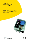
Download Pressure Transient Logger User Guide
Transcript
Pressure Transient Logger User Guide
L E I F K O C H A / S • R u g væ n g e t 3 1 • D K - 2 6 3 0 Ta a s t r u p • T e l e f o n : ( + 4 5 ) 7 0 2 3 9 8 9 8
[email protected] • www.leifkoch.dk • CVR: DK 78 06 64 15
Pressure Transient Logger User Guide
Record of Amendments
Keep this record in the front of the User Manual. When the document has been amended
write the amendment number, the date, the paragraph numbers affected by the
amendment and your initials in the table below.
Amendment
Number
Amendment
Date
Reason for Re-Issue
(Paragraph Number (s) Amended)
Amended by
1.0
18 Sept 07
First Draft
AMB
L E I F K O C H A / S • R u g væ n g e t 3 1 • D K - 2 6 3 0 Ta a s t r u p • T e l e f o n : ( + 4 5 ) 7 0 2 3 9 8 9 8
[email protected] • www.leifkoch.dk • CVR: DK 78 06 64 15
Pressure Transient Logger User Guide
Contents
Introduction
Getting Started – Start the logger recording
Downloading the recorded data
Operating Parameters
Sample Rates
Data Hysteresis
Logger Memory
Block memory
Cyclic memory
Stop Time
L E I F K O C H A / S • R u g væ n g e t 3 1 • D K - 2 6 3 0 Ta a s t r u p • T e l e f o n : ( + 4 5 ) 7 0 2 3 9 8 9 8
[email protected] • www.leifkoch.dk • CVR: DK 78 06 64 15
4
5
11
12
12
12
13
13
13
13
Pressure Transient Logger User Guide
Introduction
This manual is intended as a summary guide to using the Pressure Transient Logger
produced by Radcom Technologies Ltd.
This guide will show how the user can set up a recording and download the resulting data.
The Pressure Transient logger has been designed to capture rapidly changing pressure
conditions, such as water hammer cause by opening valves or starting pumps.
The main features of the logger include :
115200 baud communications link for fast data transfer.
Data compression for increased storage capacity
Cyclic mode for continuous logging
The kit comprises
1 x Multilog Pressure Transient Logger
1 x Pressure Transducer (calibrated to logger)
1 x PC to Logger communication cable
1 x CD with Radwin Software
1 x User Guide
L E I F K O C H A / S • R u g væ n g e t 3 1 • D K - 2 6 3 0 Ta a s t r u p • T e l e f o n : ( + 4 5 ) 7 0 2 3 9 8 9 8
[email protected] • www.leifkoch.dk • CVR: DK 78 06 64 15
Pressure Transient Logger User Guide
Getting Started – Start the logger recording
Step 1
Run Radcom View
Radcom View is running
L E I F K O C H A / S • R u g væ n g e t 3 1 • D K - 2 6 3 0 Ta a s t r u p • T e l e f o n : ( + 4 5 ) 7 0 2 3 9 8 9 8
[email protected] • www.leifkoch.dk • CVR: DK 78 06 64 15
Pressure Transient Logger User Guide
Step 2
Click the Configure Logger Wizard icon
Step 3
Change the logger type to
Multilog Pressure Transient
Step 3
Check the connection type is
Direct (RS232)
L E I F K O C H A / S • R u g væ n g e t 3 1 • D K - 2 6 3 0 Ta a s t r u p • T e l e f o n : ( + 4 5 ) 7 0 2 3 9 8 9 8
[email protected] • www.leifkoch.dk • CVR: DK 78 06 64 15
Pressure Transient Logger User Guide
Step 4
Click Next to download the
logger parameters
Wait for the parameters to
download
Step 5
The zone and location number for
the last recording are shown.
Change them if required –
instructions follow.
To keep the same zone and
location go to Step 9
L E I F K O C H A / S • R u g væ n g e t 3 1 • D K - 2 6 3 0 Ta a s t r u p • T e l e f o n : ( + 4 5 ) 7 0 2 3 9 8 9 8
[email protected] • www.leifkoch.dk • CVR: DK 78 06 64 15
Pressure Transient Logger User Guide
Step 6
Click the Select button inside the
Location Identity box.
Step 7
A list of Zones held in your
database will be listed.
Double click the required Zone.
Step 8
A list of Locations held in your
database will be listed.
Double click the required Location.
L E I F K O C H A / S • R u g væ n g e t 3 1 • D K - 2 6 3 0 Ta a s t r u p • T e l e f o n : ( + 4 5 ) 7 0 2 3 9 8 9 8
[email protected] • www.leifkoch.dk • CVR: DK 78 06 64 15
Pressure Transient Logger User Guide
Step 9
The connection type for future
communications should be direct.
Then tap next.
Step 10
Channel one configuration should
be set as default (analogue
pressure)
L E I F K O C H A / S • R u g væ n g e t 3 1 • D K - 2 6 3 0 Ta a s t r u p • T e l e f o n : ( + 4 5 ) 7 0 2 3 9 8 9 8
[email protected] • www.leifkoch.dk • CVR: DK 78 06 64 15
Pressure Transient Logger User Guide
Step 11
Set the Sample Rate
Click Next
Step 12
Set the Data Hysteresis to the required level.
Click Next
Step 13
Set the Start Time.
If a set time interval is required (i.e. the recording is between two set times) set the Stop
Time and check the Enable Stop option.
If the recording should be continuous until the data is downloaded then uncheck the
Enable Stop option.
If the recording should stop when the memory is full select Block Memory.
If the data should carry on being stored after the memory is full select the Cyclic Memory
option. Note that this may mean data from the start of the recording is lost.
Click Next
Step 14
To upload the parameters Click Next
L E I F K O C H A / S • R u g væ n g e t 3 1 • D K - 2 6 3 0 Ta a s t r u p • T e l e f o n : ( + 4 5 ) 7 0 2 3 9 8 9 8
[email protected] • www.leifkoch.dk • CVR: DK 78 06 64 15
Pressure Transient Logger User Guide
Downloading the recorded data
Step 1
Select Options > Download Data Wizard from the main menu
Change Logger Type to Multilog Pressure Transient
Click Next
Step 2
Check that the Connection Type is Direct (RS232) and the Baud Rate is 115200
Click Next
Step 3
Click Next to Download the logger parameters
Step 4
Select the correct Zone Identity and Location Identity
Click Next
Step 5
Channel Configuration should be set to default (Analogue Pressure)
Click Next
Step 6
Enter a Comment for the downloaded data
Click Next to store the data
L E I F K O C H A / S • R u g væ n g e t 3 1 • D K - 2 6 3 0 Ta a s t r u p • T e l e f o n : ( + 4 5 ) 7 0 2 3 9 8 9 8
[email protected] • www.leifkoch.dk • CVR: DK 78 06 64 15
Pressure Transient Logger User Guide
Operating Parameters
Sample Rates
Sample rates used by the pressure transient logger are:
5 Hz, 10 Hz, 15 Hz, 20 Hz, 25 Hz
Data Hysteresis
There is also a Data Hysteresis parameter. This is a “dead band” where if a reading is
within X count of the previous reading then the reading is stored as the same as the
previous reading. Using this greatly increases the memory capacity of the logger.
X is in units of 0.1m
e.g. if the Data Hysteresis is 5 and the readings are
45.2
45.7
45.4
45.8
45.6
50.3
50.7
51.3
60.0
45.8
50.7
51.3
60.0
The recorded readings are:
45.2
45.2
45.2
45.8
45.8
The net effect is that if the pressure is changing rapidly the data is accurate, whereas if the
changes are small these fluctuations can be safely ignored.
L E I F K O C H A / S • R u g væ n g e t 3 1 • D K - 2 6 3 0 Ta a s t r u p • T e l e f o n : ( + 4 5 ) 7 0 2 3 9 8 9 8
[email protected] • www.leifkoch.dk • CVR: DK 78 06 64 15
Pressure Transient Logger User Guide
Logger Memory
The data recorded in the logger memory is compressed. The actual compression ratio
depends on the nature of the data. The maximum memory capacity is 8 000 000
readings.
Block memory
If the recording fills the entire memory before the stop time is reached the recording will
stop and the stop time will be recorded
Cyclic memory
If cyclic memory is selected the recording will not stop when the memory is full. The
earliest data is overwritten and recording continues until the stop time is reached or the
data is downloaded.
Stop Time
If a recording stop time is not set the recording will continue until the logger memory is full
(Block Memory mode) or a download occurs (Cyclic Memory mode)
L E I F K O C H A / S • R u g væ n g e t 3 1 • D K - 2 6 3 0 Ta a s t r u p • T e l e f o n : ( + 4 5 ) 7 0 2 3 9 8 9 8
[email protected] • www.leifkoch.dk • CVR: DK 78 06 64 15


