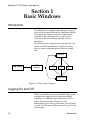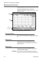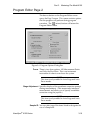
1
®
NANOSPEC 6100 SERIES
OPERATOR USERS MANUAL
Automated Film Thickness Measurement System
P/N 7500-1092 P3
Nanometrics Incorporated 1550 Buckeye Drive, Milpitas, California 95035-7418
Telephone 408•435•9600
Fax 408•232•5911
Nanometrics
NanoSpec
6100 Series
Automated Film Thickness Measurement System
Operator Users Manual
Part Number: 7500-1092 P3
Important Notice Information in this document is subject to change
without notice and does not represent a commitment
on the part of Nanometrics Incorporated.
Nanometrics Incorporated makes no warranty of any
kind with regard to this material. Neither
Nanometrics Incorporated nor its employees,
contractors, or consultants shall be liable for errors
contained herein or for incidental or consequential
damages in connection with the furnishing,
performance, or use of this material.
Copyright Notice © 1998 Nanometrics Incorporated
This document contains proprietary information
which is protected by copyright. All rights are
reserved. No part of this document may be
reproduced, transmitted, stored in a retrieval system,
or translated into any human or computer language,
in any form or by any means, electronic, mechanical,
magnetic, optical, chemical, manual, or otherwise,
without the prior written permission of the copyright
owner, Nanometrics Incorporated, 1550 Buckeye
Drive, Milpitas, California 95035-7418. Copyright
infringement carries with it serious civil and criminal
penalties under the United States and foreign
copyright laws.
This manual describes a product which includes
copyrighted software. Said software is licensed to the
customer for use only in accordance with the license
agreement.
Printed in the United States of America
December 1999
Part Number 7500-1092 P3
ii
Nanometrics
Table of Contents
Frontmatter
Lock-out/Tag-out Procedures.................................................................................. v
About This Manual ................................................................................................... v
How To Use This Manual ........................................................................................ v
Who Should Use This Manual .............................................................................. vii
Additional Sources of Information....................................................................... vii
Manual Conventions .............................................................................................. vii
Federal Communications Commission Radio Frequency
Interference Statement ............................................................................................ x
Part 1: Perusing the Model 6100
Section 1 Introduction ............................................................................................... 1-2
System Features ..................................................................................................... 1-2
Turning Off the Instrument ................................................................................. 1-3
Section 2 System Components ................................................................................. 1-4
Measurement System ........................................................................................... 1-4
Stage ........................................................................................................................ 1-4
System Controller Tower ..................................................................................... 1-5
Computer Components ........................................................................................ 1-6
Section 3 Reference Wafer ......................................................................................... 1-8
Standard Reference ............................................................................................... 1-8
Reflectance Reference ........................................................................................... 1-8
UV Option References .......................................................................................... 1-8
Section 4 Measurement Spot .................................................................................... 1-9
Spot Placement ...................................................................................................... 1-9
Spot Size ............................................................................................................... 1-10
Part 2: The Model 6100 Basics
Section 1 Basic Windows ........................................................................................... 2-2
Introduction ........................................................................................................... 2-2
Logging On and Off .............................................................................................. 2-2
Main Operating Screen ......................................................................................... 2-4
Selecting Programs ............................................................................................... 2-6
Measurement Screen ............................................................................................. 2-8
Measuring a Sample ........................................................................................... 2-10
Section 2 Film Thickness Maps .............................................................................. 2-11
Introduction ......................................................................................................... 2-11
Creating a Map .................................................................................................... 2-12
Nanometrics
iii
Map Type Examples ........................................................................................... 2-16
Part 3: Mastering The Model 6100
Section 1 Introduction ............................................................................................... 3-4
Introduction ........................................................................................................... 3-4
Creating Programs ................................................................................................ 3-4
Maintaining Programs .......................................................................................... 3-7
Section 2 User Editor ................................................................................................. 3-9
Introduction ........................................................................................................... 3-9
User Editor Screen ............................................................................................... 3-10
Section 3 Program Editor ........................................................................................ 3-15
Program Maintenance Screen ............................................................................ 3-15
Program Editor Screen ....................................................................................... 3-17
Program Editor Page 2 ....................................................................................... 3-19
Section 4 Measurement
Program Editor ........................................................................................................ 3-21
Introduction ......................................................................................................... 3-21
Measurement Editor Screen ............................................................................... 3-23
Measurement Editor Page 2 .............................................................................. 3-24
About Reference Scans ....................................................................................... 3-25
Section 5 Recalibration Editor ................................................................................ 3-26
Introduction ......................................................................................................... 3-26
Recalibration File Window ................................................................................ 3-26
Recalibration Parameter Window ..................................................................... 3-28
Section 6 Stage Program Editor .............................................................................. 3-30
Introduction ......................................................................................................... 3-30
Stage List Window .............................................................................................. 3-30
Stage Editor Window .......................................................................................... 3-32
Section 7 Loader Program Editor ........................................................................... 3-36
Introduction ......................................................................................................... 3-36
Loader Program List ........................................................................................... 3-36
Loader Editor Program Window ...................................................................... 3-37
Appendice
Appendix A Notes on Standard Programs
Appendix B Notes on Standard UV Programs
SECS II
SEMI Equipment Communications Standard
iv
Nanometrics
Lock-out/Tag-out Procedures
1.
2.
3.
4.
5.
Turn off main circuit breaker power switch.
Turn off main circuit breaker located at the
facilities panel and use lockout/tag-out lock
meeting end user guidelines. Lock is not
provided by Nanometrics.
Unplug the power supply cord to the Controller
from both the Controller unit and the AC power
distribution receptacle.
Unplug power cords connected to the output
receptacles on the controller unit.
Device identification and tags for lock-out/tagout of this tool is to follow the guidelines of the
end user.
About This Manual
This manual provides the information you need to
operate and program the NanoSpec® 6100, to be
known from here on as Model 6100, Automated Film
Thickness (AFT) Measurement System. If some points
are unclear while operating the software, refer to the
On-line Help.
How To Use This Manual
This manual covers procedures for the Model 6100 in
the Production Mode and Process Engineer Mode
(referred to in this manual as the Operations Mode
and Engineering Mode, respectively). These
procedures are divided into four parts under which
are further divided into sections. System operators
are responsible for Part 1 and Part 2. System
engineers are responsible for all parts of the Manual.
Part 1: Perusing the Model 6100 Features consists of
the following:
This section is a general overview of the Model 6100,
its capabilities, system components, and controls and
indicators. The section covers precautions, preoperation procedures, power-up and initialization
procedures, and power-down procedures.
Nanometrics
v
Part 2: Learning the Model 6100 Process Basics consists of the following:
Section 1—Basic Windows—explains everything
operators need to know to operate the Model 6100:
logging on and off; selecting measurement programs;
taking reference scans; taking measurements of the
sample wafers; displaying and printing raw
measurement lists and interferograms of these
measurements; and creating maps of film thickness
uniformity from current measurements.
Section 2—Maps of Film Thickness—explains how to
view lists and statistics associated with saved
measurements and how to create maps of film
thickness uniformity from current measurements.
The measurements stored here can be used in the
creation of maps of the uniformity of film thickness on
wafers, or in statistical analysis.
Part 3: Mastering the Model 6100 Features consists of
the following:
The information contained in this section is important
to process engineers who must design custom
measurement programs.
Section 1—Introduction—gives a general overview of
the process of creating or editing measurement
programs for the Model 6100.
Section 2—User Editor—explains how to set or change
parameters related to a user’s access to programs
previously created and to the editors used to create a
program.
Section 3—Program Editor— explains how to create,
edit, or change the associated measurement programs
of the program.
Section 4—Measurement Program Editor—explains
how to set or change parameters related to film type
and about reference scans.
Section 5—Recalibration—explains how create, edit, or
change a recalibration file. Recalibration is the
function of the Model 6100 to compensate for
differences between instruments.
Section 6—Stage Program Editor— explains how to set
or change the pattern of measurement points used to
measure your wafer (facilitated by stage movement).
vi
Nanometrics
Section 7—Loader Program Editor—explains how to set
and change the wafer from a cassette in the auto
loader.
Who Should Use This Manual
...for Operation The operation of the Model 6100 is intended for
production personnel, process engineers, and
Nanometrics trained service personnel.
Production personnel should read Part 1 and Part 2
and then, if necessary, Part 4 to check on the details of
individual programs.
Process engineers and service engineers should read
Part 1 through Part 4 to become thoroughly familiar
with the instrument.
...for Maintenance The Model 6100 is a very complex electro-mechanical
device consisting of a precision
microspectrophotometer system. Because of the
machine’s complexity, it should be installed and
serviced only by either service engineers from
Nanometrics or others who have completed
Nanometrics service training classes. These training
classes provide a thorough understanding of the
operation of the machine and instructs personnel on
the use of the system’s support tools.
For information about training, contact the
Nanometrics Customer Support at (800) 955-6266 or
(408) 746-1600.
Additional Sources of Information
For any additional questions on installation and
maintenance, you may contact Nanometrics Customer
Support at (800) 955-6266 or (408) 746-1600.
Consult your local library or bookstore for books on
concepts in microscopy and spectroscopy.
Manual Conventions
This manual uses the following typographic
conventions:
Nanometrics
vii
Keyboard Conventions
Key Cap Names The names of key caps on the computer keyboard are
spelled out and appears bold in angle brackets. Some
example key caps are shown as:
<Esc>, <Enter>, <F1>, <Ctrl>
Key Combinations A plus sign between two or more key names means
that you must hold down the first key while pressing
the next key. For example, the instruction:
Press <Ctrl> + <F10>
means “Press the <Ctrl> key and while holding it
down, press the <F10> key.” As soon as you have
completed these steps, you can release all keys.
What You Type Commands or responses to prompts that you should
type as indicated in the instructions are shown in
quotes. For example, you type:
y
in response to the instruction, Type “y” in response to
the prompt.
All screen buttons (which you click on with your
mouse) appears bold. Some screen buttons examples
are shown as:
Cancel, Enter, Exit
Trackball Assembly Functions
The trackball assembly consists of a ball, which is
rolled to move the cursor on the screen, and a left and
right button, which are used to access screens and
windows and activate commands.
Left Button The left button is used for the following:
• Selecting a film program or lens in either the
Operations Mode or the Engineering Mode. If you
click once with the left button, the window
appears, requiring you to click on the ENTER
command button to load your selection into the
program.
When you double-click (rapidly) you can enter the
film-type or lens-type window without having to
click on the ENTER command button.
viii
Nanometrics
• most engineering and service maintenance
functions, which are activated with a single click.
• accessing the database in the Engineering Mode,
which is activated by a single click only.
Please be patient after clicking once, as it takes up to
15 seconds to load all the files from the database
before a screen prompt appears.
Right Button The right button is used for the following:
• when you are at the most detailed level of the
screen displaying the database in the Engineering
Mode.
With a single click of the right button, a pop-up
menu appears on this screen. This menu gives you
the choice of all the menu options at the top of the
screen when the left button is already engaged in
selecting (highlighting) multiple measurements.
• when the cursor is in the User ID field of the Logon
window. A single click of the right button shuts
down the system.
Screen Conventions
• Names given to unlabeled screens or windows for
convenience of reference are capitalized and
appear in quotes, such as “GRAPH DISPLAY
SCREEN”.
• Program names not displayed as the name of a
window, screen, field, or menu option are initial
capitalized, such as the Engineering Mode or
Operations Mode.
• Screen prompts or messages (which are not part of
the above-mentioned screens or windows) are
shown bold and in quotes. An example is:
“Measuring...”
Terminology
In this manual, the following terms are defined below.
Click The left side switch on the track ball, press and release
quickly.
Double Click Two successive clicks in a short interval.
Nanometrics
ix
Drop-down Menu An appearing menu when clicking on a menu item.
Log-on Entering User ID and Password to enter the software
program with operator or engineer privileges.
Log-off Removes the previous User ID and prepares for the
next Log-on.
Federal Communications Commission Radio
Frequency Interference Statement
This equipment generates and uses radio frequency
energy. If not installed and used in strict accordance
with the manufacturer's instructions, the equipment
may cause interference with radio communications. It
has been type tested and found to comply with the
limits for a Class A computing device in accordance
with the specifications in Subpart J of Part 15 of FCC
Rules, which are designed to provide reasonable
protection against such interference when operated in
a commercial environment. Operation of this
equipment in a residential area is likely to cause
interference, in which case whatever measures
required to correct the interference must be taken at
the owner's expense. (FCC, Part 15.818a)
Instructions to User If this equipment does cause interference to radio or
television reception, the user is encouraged to try to
correct the interference by one or more of the
following measures:
• Re-orient the receiving antenna.
• Relocate the equipment with respect to the
receiver.
• Move the equipment away from the receiver.
• Plug the equipment into an outlet that is on a
different circuit branch than the receiver.
If necessary, the user should consult the dealer or an
experienced radio/television technician for additional
suggestions.
The user may find the following booklet prepared by
the Federal Communications Commission helpful:
How to Identify and Resolve Radio-TV Interference
Problems. This booklet is available from the U.S.
Government Printing Office, Washington DC 20402.
Stock No. 004-000-00345-4.
x
Nanometrics
Part 1
Perusing the Model 6100
The following topics are covered in this section:
Section 1 Introduction ......................................................................................................... 1-2
System Features ................................................................................................................. 1-2
Turning Off the Instrument ............................................................................................. 1-3
Section 2 System Components ...........................................................................................
Measurement System .......................................................................................................
Stage ....................................................................................................................................
System Controller Tower .................................................................................................
Controller Front Panel Controls.................................................................................
Controls Behind the Panel Door ................................................................................
Computer Components ....................................................................................................
Computer Monitor.......................................................................................................
Keyboard .......................................................................................................................
Trackball........................................................................................................................
Joystick...........................................................................................................................
Optional Printer ...........................................................................................................
1-4
1-4
1-4
1-5
1-5
1-5
1-6
1-6
1-6
1-6
1-7
1-7
Section 3 Reference Wafer ...................................................................................................
Standard Reference ...........................................................................................................
Reflectance Reference .......................................................................................................
UV Option References ......................................................................................................
1-8
1-8
1-8
1-8
Section 4 Measurement Spot .............................................................................................. 1-9
Spot Placement .................................................................................................................. 1-9
Spot Size ........................................................................................................................... 1-10
NanoSpec® 6100 Series
1-1
NanoSpec® 6100 Series User Manual
Section 1
Introduction
IntroductionThe NanoSpec® 6100 Automated Film
Thickness (AFT) Measurement System, hereafter
referred to as the Model 6100 or M6100, is an
instrument designed to measure the thickness of films
deposited on various substrates including those used
in semiconductor and magnetic head fabrication. The
Model 6100 provides accurate and repeatable
measurements in manufacturing and advanced
research/development environments.
System Features
The Model 6100 offers these important features and
options:
• Linear array head
• Small spot size
• Fast focus
• Fast measurements
• Broad thickness ranges
• Multipurpose thin and thick film capability
• Continuous scanning from 210–800 nanometers
• Optional UV capabilities for measuring very thin
films (25Å–500Å)
• Windows 95 ™ based graphical user interface
• Standard and customized film programs
• 2D and 3D wafer-mapping software
• Database storage of measurements
• Real-time sample and model interferogram
plotting
• Automated focusing
• Joystick-automated stage
• 32-bit Pentium™ microprocessor
1-2
Nanometrics
Perusing Model 6100
• Joystick, keyboard, and trackball assembly
The measurement range of the Model 6100 extends
from 25–200,000 Å (0.0025–20 micrometers). The
optional UV system allows measurements at 25Å–
500Å.
Turning Off the Instrument
To turn off the Model 6100, the user has to be assigned
the privilege to exit the Nano system software.
1. Click on the LOGON command button on the
Operations Mode screen.
2. Type in your User ID and Password when the User
ID/Password window appears.
3. Click on the Exit (Shutdown) item and select:
• Exit to Windows—if you want to shutdown the
Nano system software.
• Shutdown Windows—if you want to shutdown
the complete system.
NanoSpec® 6100 Series
1-3
NanoSpec® 6100 Series User Manual
Section 2
System Components
The following simplified drawing of the Model 6100
gives you a visual reference for a discussion of the
system’s hardware components.
Measurement System
In the Model 6100, the spectrophotometer head is
mounted on a customized microscope that uses a
regulated tungsten halogen lamp to provide vertical
reflected light illumination. The standard microscope
is equipped with a four position turret. The lenses are
4X, 10X, and 40X. An optional 15X ultraviolet (UV)
lens is available. The 40X lens is the system parfocal
and parcenter lens.
Optional Scanning UV System
Systems equipped with the optional UV scanning
includes a deuterium UV light source, an
accompanying power supply, an UV light shutter, an
UV-optimized beamsplitter, an automatic variable exit
aperture, and a 15X reflecting UV objective lens.
Stage
The Model 6100 stage is capable of accommodating
100mm/150mm wafers or 150mm/200mm wafers.
The stage is automatically driven to predefined
measurement points. These points are defined in the
stage editor. The standard Model 6100 stage is the
manual loader model, and Model 6150 stage
accommodates an optional automatic loader.
1-4
Nanometrics
Perusing Model 6100
System Controller Tower
The System Controller Tower is the main electronic
control center for the M6100 instrument. The
controller tower houses four D/C power supplies,
X/Y/Z stage axis electronics, electronic focusing
control board, and system A/C power distribution
bus.
Controller Front Panel Controls
The three main front panel controls are available:
Emergency Power Off The first front panel control is the Emergency Power
Button Off Button. This button is a large red button on the
upper right hand corner of the front panel. This
button is over size and set within edge cup. This is to
ensure that the button is not depressed by accident.
The button is depressed to remove all equipment A/C
power. When the Emergency button is pressed, the
main A/C power circuit breaker switch has to be
cycled to restore the equipment A/C power.
Power On Button The main Power On Button of the Model 6100 system
is a round button located on the upper right section
and under the Emergency Button. The power on
indicator is a amber lamp luminating the Power On
Button.
Power Off Button The main Power Off Button of the Model 6100 system
is a round button located on under the Power On
Button. The power off indicator is a amber lamp
luminating the Power Off Button.
Controls Behind the Panel Door
Computer Controls and The computer indicators and controls are present on
Indicators the computer front panel and are discussed within the
vendor manual.
UV Lamp Power On the lower left hand side of the panel is the A/C
power switch for the UV Lamp Power Supply.
NanoSpec® 6100 Series
1-5
NanoSpec® 6100 Series User Manual
Main A/C Power To the left of the UV Lamp switch is the Main A/C
Power switch. This switch is also the main circuit
breaker for the system.
Computer Components
The primary computer is mount behind the Controller
front panel. The supporting computer components
are:
Computer Monitor
A 15-inch SVGA monitor displays menus, commands,
instructions, graphs, maps, and a color video image of
the sample. The computer monitor discussion is
presented in the vendor manual.
Keyboard
The Model 6100 keyboard is primarily used to
perform alphanumeric data entry when programming
or running the system. However, you can use some
function keys as alternatives to clicking the pointer on
the corresponding user interface buttons.
Trackball
The graphic user interface pointer is controlled by the
trackball. The trackball assembly consists of a large
ball and two large buttons that make it easy to operate
when wearing gloves. The trackball is used to control
the computer pointer, and the buttons are used to
control the user interface.
The trackball's left button is used to control the Model
6100 system software. You can select items from the
system's menus in two ways:
• Click the pointer on an item to highlight it and
then select it by clicking the pointer on an ENTER
or OK button.
• Double click the pointer on an item to both
highlight and select it.
1-6
Nanometrics
Perusing Model 6100
Joystick
The joystick is used to control the stage movement
manually when programming a stage pattern or when
measuring without an automatic stage pattern.
Optional Printer
An optional color graphics printer can be used to print
measurements, statistical results, interference plots
and wafer maps (on instruments equipped with the
wafer mapping option) on clean room-compatible
paper.
NanoSpec® 6100 Series
1-7
NanoSpec® 6100 Series User Manual
Section 3
Reference Wafer
Using the proper reference sample is important
because the instrument functions by scanning your
reference (typically your substrate material) and
storing the intensity data in memory. The stored
reference data is then used to obtain the reflectance for
the film(s) being measured.
You will need one of the following references to
perform measurements with the Model 6100:
Standard Reference
A clean, bare silicon wafer is typically used as the
reference for all standard measurement programs. For
more information on the standard programs, see
“Notes on Standard Programs” in Appendix A.
Reflectance Reference
The Reflectance Mode program (12) enables you to
measure reflectance relative to silicon. When
performing absolute reflectance measurements in a
user-defined program, you must also use a bare silicon
reference wafer.
UV Option References
For more information on the standard programs using
the UV option, see “Notes on UV Standard Programs”
in Appendix B.
1-8
Nanometrics
Perusing Model 6100
Section 4
Measurement Spot
The video display of the viewing area shows light
reflected from the instrument's entrance aperture disk
(a mirror in the optical stack with a hole in it). The
black measurement spot you see is the actual entrance
aperture--the hole in the mirror.
The measurement spot is black because that portion of
the light is not being reflected from the disk. Instead,
it travels into the spectrophotometer head to be
measured.
Only the area under the black spot is measured by the
instrument because this is the only light that travels
into the spectrophotometer head.
Spot Placement
Use the following guidelines to locate the best point
for measurement:
• When measuring small features on patterned
wafers, use a lower-powered objective lens to find
the general area of a feature. When you find it,
change to the lens you want to measure with.
• When measuring on a patterned wafer, position
the measurement spot (or program it to be
positioned) in the center of the feature you want to
measure.
• When measuring on an unpatterned wafer,
position the measurement spot (or program it to be
positioned) in the area you want to measure.
NanoSpec® 6100 Series
1-9
NanoSpec® 6100 Series User Manual
Spot Size
The measurement spot must be small enough to be
placed completely within the area of the feature being
measured. The objective lens that you select
determines the size of the measurement spot.
If the measurement spot is larger than the feature
being measured, use a higher-powered objective lens.
The following chart shows the relationship between
the objective lens used and measurement spot size.
Use this chart to change the size of the measurement
spot.
Table 2-1: Relationship between lens power and spot size
1-10
Standard 6100
Visible System
Optional 6100
UV System
Lens Power
Spot Size (microns)
Spot Size (microns)
4X
62.5
62.5
10X
25
--
15X
--
17.8
40X
6.25
6.25
Nanometrics
Part 2
The Model 6100 Basics
The following topics are covered in this chapter:
Section 1 Basic Windows .................................................................................................... 2-2
Introduction ....................................................................................................................... 2-2
Logging On and Off .......................................................................................................... 2-2
Entering a User ID and Password ............................................................................. 2-3
Logging Off................................................................................................................... 2-3
Main Operating Screen ..................................................................................................... 2-4
Selecting Programs ........................................................................................................... 2-6
Measurement Screen ........................................................................................................ 2-8
Information Band ......................................................................................................... 2-8
Display Area ................................................................................................................. 2-8
Display Type................................................................................................................. 2-8
Action Buttons ............................................................................................................ 2-10
Measuring a Sample ....................................................................................................... 2-10
Section 2 Film Thickness Maps ........................................................................................
Introduction .....................................................................................................................
Kinds of Display.........................................................................................................
Kinds of Maps.............................................................................................................
Creating a Map ................................................................................................................
General Overview ......................................................................................................
Search Database..........................................................................................................
Search Results Window ......................................................................................
Display Measurement Data ................................................................................
Map Type Examples .......................................................................................................
Numeric Map..............................................................................................................
2D Contour Map ........................................................................................................
3D Map ........................................................................................................................
NanoSpec® 6100 Series
2-11
2-11
2-11
2-11
2-12
2-12
2-12
2-14
2-14
2-16
2-16
2-16
2-17
2-1
NanoSpec® 6100 Series Users Manual
Section 1
Basic Windows
Introduction
The Model 6100 is capable of performing a variety of
tasks in the Production Mode (the Operations Mode).
This section provides an overview of the features
available to the production user, as well as basic
instructions on measurement and data analysis
procedures.
The following flow diagram shows the path the user
follows to make measurements, display and print
data, or create an interferogram to analyze sample
data.
Database
AFT
Screen
Log On/Off
List
Graph
Map
Measurement
Figure 2-1 Process Flow Diagram
Logging On and Off
When you initially turn on your Model 6100, you are
automatically logged onto the Operations Mode,
enabling you to perform measurements as well as
gather and analyze data. However, if you
subsequently press the Log On button, you will need
to use a User ID name and password to Log On to the
system again.
2-2
Nanometrics
Part 2: Model 6100 Basics
The User is assigned an User ID name and password,
by the system administrator, with certain privileges.
This section will assume that the user has only
password privileges. The engineering privileges are
discussed later in Part 3 of this manual.
Entering a User ID and Password
When an User presses Log On button, the M6100 Log
On dialog box appears.
1. Click the pointer in the User ID name field.
2. Type your assigned User ID name.
3. Press the <Tab> key or click in the Password field.
4. Type your assigned password.
5. Click on the Log On button or press the <Enter>
key.
The Main Operating Screen appears.
NOTE
If the Log On procedure is not successful, type
the User name and password in capitals. The
Log On dialog box is case sensitive. If the Log
On is still unsuccessful, contact the system
administrator at your facility.
Logging Off
To log off the Model 6100:
1. Click on the F3:Log On button in the Operations
Mode screen or press the <F3> key on your
keyboard.
The Log On dialog box appears.
NOTE
At this time, the software leaves the user name and
password intact. A non-entity user should have
been created for safe guarding the system.
2. Type the non-entity User ID name.
3. Press the <Tab> key or click in the Password field.
4. Click on the Log On button or press the <Enter>
key.
NanoSpec® 6100 Series
2-3
NanoSpec® 6100 Series Users Manual
Main Operating Screen
The Operations Mode screen is displayed when you
Log On to the system. The rest of this chapter
describes the options displayed on this screen and
how to use the ones that are available to a operator on
the Model 6100. All Operation functions available to
the operator are present on this screen. Any function
displayed on the screen that is not assigned to the
User privilege level is not activated.
The Main Operation Screen contains of the following
areas: title band, menu bar, User identification band,
program listing area, and action button area.
Title Band
Menu Bar
User Informational
Band
Program
Listing
Action Button
Area
Figure 2-2 Basic Operator Screen
Title Band The title band displays the screen title.
Menu Bar The menu bar displays the available option items.
The options are:
Edit
All functions in this menu item are deactivated for the
User assigned with no privileges.
Maintenance
This menu item has drop down menu items: Reference
Info.–selecting this item opens an information
window showing the Date and time when the last
2-4
Nanometrics
Part 2: Model 6100 Basics
reference was taken; Delete Reference– selection this
item deletes the reference measurement stored in
memory.
Data
This menu item contains the following: Process Last
Saved Measurement Result—measurements are
automatically saved to a database. This item allows
the operator to process data after all measurements are
completed; Process Measurement Result—this item
allows the operator to process a measurement just
taken without searching the database. See “Film
Thickness Maps” on page 11.
About
This menu item contains the following: AFT–opens a
informational window displaying information about
the AFT software; Windows–opens a informational
window displaying information about the Window
software.
Exit(Shutdown)
This menu item contains the following:
1. [Exit to Windows]
Shuts down the system software only. Exit
Windows before turning off the equipment
2. [Exit to DOS]
Shuts down both the system software and
Windows. However, if another windows
application is still running, only the system
software will be shut down (proceed as described
above).
Debug
This menu item is deactivated for the User assigned
no privileges.
User Identification This band is an information area displaying the user
Band name, date and system time.
Program Listing Area The program listing area is the main portion of the
screen display. This area displays the programs
available for measurements.
Action Button Area This area contains direct action buttons. The buttons
can be activated by clicking on the button with the
pointer or by pressing the <Fn> key displayed in the
button.
NanoSpec® 6100 Series
2-5
NanoSpec® 6100 Series Users Manual
F1:Help
The Help button and F1 key opens the M6100 Help
file.
IMPORTANT
The Help button in most screens are content
sensitive. That is, in the Measurement Editor, the
Help button will open the file and display the
information pertaining to the Measurement Editor.
F2:Video
The Video button and F2 key is a toggle switch to turn
on/off the video image window.
F3:Log On
The Log On button and F3 key will remove the User
ID from the User identification band and open a Log
On dialog box.
F4:Gain
The Gain button and F4 key is deactivated on the
M6100. The gain is automatic adjusted by software.
F5:A.F.
The A.F. (auto focus) button and F5 key focuses the
lens on the sample.
Selecting Programs
Before a user can take any measurements, a program
must be selected and loaded. The main operating
screen displays up to 200 pre-defined programs. The
programs have been defined using the instrument in
the engineering mode; so the operator can easily
measure a sample by selecting and activating a
program.
To load a program:
1. Load a reference wafer on the reference platform
(right platform) of the stage.
2-6
Nanometrics
Part 2: Model 6100 Basics
2. In the Program listing area of the display, select a
program by clicking on a program to highlight it.
NOTE
Double click or press <Enter> mean the same
thing. From this point on, double click will be used
without referencing the key board. Either method
can be used, it is your choice.
3. Double click on the program.
The measurement window appears, the stage
moves for a dark reference measurement, and
reference reminder box opens.
NOTE
UV program references are taken every two
hours; VIS program references are taken every
four hours.
4. If the reference time is within your limit, click on
No.
5. If the reference is out of your limit, click on Yes.
The stage moves to allow you to load wafer.
6. With wand, load a sample wafer.
7. Click OK.
The stage moves and takes the measurement and
displays the measurement in the Measurement
Screen.
NanoSpec® 6100 Series
2-7
NanoSpec® 6100 Series Users Manual
Measurement Screen
The Measurement screen is the work area that is used
to display measurement data. To aid in the
discussion, the display is divided into four areas. The
display areas are::
Information
Band
Display
Area
Display Type
Action Buttons
Figure 2-3 Defining the Measurement Screen
Information Band
The Information Band displays Program and Sample
ID.
Display Area
The Display Area sets up the data into a visual
presentation. There are three display methods: List,
Graph, and Map.
Display Type
The Display Type has three buttons and two stage
numerical position displays.
List Button The List button is the default display in the above
display area. The list is numerical measurement data.
2-8
Nanometrics
Part 2: Model 6100 Basics
Graph Button The Graph button displays the measurement data list
in an interferogram graph.
Figure 2-4 Example of Graph Display
Map Button The Map button displays the measurement points on a
wafer graph. The statistics are also displayed on the
right side.
Figure 2-5 Example of Map Display
X Position The X position is the left and right stage movement
from the center point and is expressed numerically.
The stage movement is controlled by the joystick or
the program.
NanoSpec® 6100 Series
2-9
NanoSpec® 6100 Series Users Manual
Y Position The Y position is the forward and backward stage
movement from the wafer center point and is
expressed numerically. The stage movement is
controlled by the joystick or the program.
Action Buttons
This screen band contains action buttons use while
taking measurements. The buttons are:
Help The Help button is content sensitive. Press to receive
additional information on the screen functions.
Stat The Stat button opens another display box displaying
the statistic data. A screen opens and displays a bar
graph of the measurement data.
Ref The Ref button is available take reference
measurements. This button is deactivated when in the
operator mode.
Meas The Meas button starts the measurement process.
New Test The New Test button saves the measurement data in a
database and clears the data from the screen. The
screen is ready to start another measurement.
Calib The Calib button saves the measurement data and
closes the measurement window and returns the Main
Operation Screen.
Video The Video button is a toggle button. This button turns
the video image window on/off. The video image is a
overlayed on the screen.
Measuring a Sample
After you have selected a program and performed the
reference scans, the instrument is ready to take
measurements.
The general procedure to measuring a sample is the
following:
1. Place a sample wafer onto the stage.
2. Using the A.F. button, focus on the wafer.
3. Position the stage so that the lens is over the
desired measurement spot.
4. Select the appropriate program.
5. Using the Meas button, measure the sample.
2-10
Nanometrics
Part 2: Model 6100 Basics
Section 2
Film Thickness Maps
Introduction
A special feature of the Model 6100 is the drawing of
contour thickness maps. These contour maps are only
drawn after the sample measurements are stored in
the database. This section will describe how to create
and display a contour map.
The Map program uses film thickness measurement
data to extrapolate an image called a “map” which
gives you a graphic representation of the uniformity of
film thickness on a sample wafer. The measurement
data must contain three or more measurement points
to create a map (a map of only two points will be
meaningless). A minimum of nine points is
recommended to create a map that is useful for
analysis.
Kinds of Display
Ten contours are drawn on the map to represent the
intervals, or boundaries, of the measured thickness.
These contours can be displayed in a two-dimensional
map where they are used to emphasize the discrete
intervals (boundaries) of thickness. The intervals can
also be represented as concentric thickness-coded
color bands in two-dimensional or three-dimensional
maps. The three-dimensional color map gives the
most realistic view of the thickness variations.
Kinds of Maps
The user has the option of creating one of four kinds of
maps:
• Numeric—is a display map showing numeric values
at the measurement point on the wafer. This map
can be used with all stage pattern generation
methods.
NanoSpec® 6100 Series
2-11
NanoSpec® 6100 Series Users Manual
• Line—is a display map showing a wafer edge view
of the film thickness. This map is mostly used when
the stage pattern generation is a straight line.
• 2D—is a display map showing the film thickness
with contour lines between measurement points.
This map is used with all stage pattern generation
methods, except line.
• 3D—is a display map showing a realistic
representation of the film thickness. This map is
used with all stage pattern generation methods,
except line.
Creating a Map
This section will guide the user through the steps to
create a realistic map.
General Overview
All maps are drawn using previous measurement
results. The general procedure is:
1. Take your thickness measurements, as described in
“Measuring a Sample” on page 3-10.
2. In the Data drop down menu, select the Process
previous measurement result item.
3. Search the database for sample measurement
data. See “Search Database” on page 3-12.
4. Display the measurement data. See “Display
Measurement Data” on page 3-14.
5. Select map style for the display. See “Map Type
Examples” on page 3-16.
Search Database
Wafer measurements are automatically entered into
the software database. Creating a map uses data that
has been entered into the Database. When the Process
2-12
Nanometrics
Part 2: Model 6100 Basics
previous measurement data is selected from the Data
drop down menu, the Search Data utility window
opens.
Figure 2-6 Search Data Window
The measurement data is stored in the database with
additional information that can be used in searching
the Database. The additional information is:
Program The Program name, that was used to take the
measurement, is saved with the data.
User ID The User ID, of the person that took the data
measurement, is saved with the data.
Date and Time The Date and Time, when the measurement was
taken, is saved with the data. When the Date and
Time button is clicked, an additional dialog box opens.
Figure 2-7 Date and Time Dialog Box
Use the spin dials in the Start and End boxes to narrow
the range. Check the Specify Time box if time is to be
used . The check box in the upper left corner is used
to enable the Date and Time search criteria.
NanoSpec® 6100 Series
2-13
NanoSpec® 6100 Series Users Manual
Sample ID The Sample ID, if there is a wafer identification code,
is saved with the data.
The above items allow the database to be searched and
narrows the search to specific criteria.
Search Button
The Search button starts the search with the selected
criteria. At completion, the Search Results window
opens.
Exit Button
The Exit button cancels the search operation and
returns to the operation screen.
Search Results Window
After search completion, the Search Results Window
opens. This window displays a list of all wafer
measurement data found in the database fitting the
search criteria.
Figure 2-8 Search Results Window
Select (highlight) a measurement set and click on the
Simple Data button. The Display Measurement Data
window opens.
Display Measurement Data
The Display Measurement Data window displays
numerical data for thickness, fit, and wafer X and Y
position of each measurement point. The active
2-14
Nanometrics
Part 2: Model 6100 Basics
buttons at the bottom of the window are used as a
gateway to the different map types. The active
buttons are:
Figure 2-9 Display Measurement Data Window
Search The Search button returns the Search window for
another search query definition.
List The List button opens a display showing a simple list
of the measurement thicknesses.
Numeric The Numeric button opens a map window displaying
a wafer map with numeric thicknesses displayed at
the each wafer location. See “Map Type Examples”
below.
Line The Line button opens a map window displaying a
side view of the wafer thickness. This mapping
technic is best used with straight line stage patterns.
2D/3D The 2D/3D button opens a selection box whick allows
selection of 2D Contour Line, or 2D Contour Area, or
3D Contour Line maps. See the “Map Type
Examples” below.
Print If the printer is configured for the system, the Print
button sends the measurement data to the printer for a
hardcopy of the measurement list.
Exit The Exit button exits the mapping and returns to the
operating screen.
NanoSpec® 6100 Series
2-15
NanoSpec® 6100 Series Users Manual
Map Type Examples
Numeric Map
Figure 2-10 Numeric Map Example
2D Contour Map
Figure 2-11 2D contour Map Example
2-16
Nanometrics
Part 2: Model 6100 Basics
3D Map
Figure 2-12 3D Map Example
NanoSpec® 6100 Series
2-17
NanoSpec® 6100 Series Users Manual
2-18
Nanometrics
Part 3
Mastering The Model 6100
The following topics are covered in this section:
Section 1 Introduction .........................................................................................................
Introduction .......................................................................................................................
Creating Programs ............................................................................................................
General Overview ........................................................................................................
General Procedure .......................................................................................................
Maintaining Programs .....................................................................................................
3-4
3-4
3-4
3-5
3-5
3-7
Section 2 User Editor ........................................................................................................... 3-9
Introduction ....................................................................................................................... 3-9
System Administrator ................................................................................................. 3-9
Process Engineer .......................................................................................................... 3-9
Service Engineer......................................................................................................... 3-10
Operator ...................................................................................................................... 3-10
User Editor Screen .......................................................................................................... 3-10
User Dialog Box.......................................................................................................... 3-11
Access Level Dialog Box ........................................................................................... 3-12
Program ................................................................................................................. 3-12
Measurement ........................................................................................................ 3-12
Lens Parameter..................................................................................................... 3-12
Recalibration ......................................................................................................... 3-12
Stage Program ...................................................................................................... 3-12
Loader Program ................................................................................................... 3-12
Secs Setup.............................................................................................................. 3-13
System Shutdown ................................................................................................ 3-13
Data Maintenance ................................................................................................ 3-13
SECS Operation .................................................................................................... 3-13
User ........................................................................................................................ 3-13
Password ............................................................................................................... 3-14
Gain[Setup] ........................................................................................................... 3-14
Model6100 Setup.................................................................................................. 3-14
Maintenance Menu .............................................................................................. 3-14
Section 3 Program Editor .................................................................................................. 3-15
Program Maintenance Screen ........................................................................................ 3-15
NanoSpec® 6100 Series
3-1
NanoSpec® 6100 Series User Manual
Program Editor Screen ................................................................................................... 3-17
Program Editor Page 2 ................................................................................................... 3-19
Section 4 Measurement Program Editor .........................................................................
Introduction .....................................................................................................................
Measurement Editor Screen ..........................................................................................
Material Button...........................................................................................................
Command Buttons .....................................................................................................
Measurement Editor Page 2 ..........................................................................................
Reference Parameters ................................................................................................
Graph Scale Parameters ............................................................................................
About Reference Scans ...................................................................................................
3-21
3-21
3-23
3-23
3-23
3-24
3-24
3-25
3-25
Section 5 Material Editor ...................................................................................................
Introduction .....................................................................................................................
Create Material Screen ...................................................................................................
Create New Buttons...................................................................................................
Cauchy without k.................................................................................................
Cauchy with k.......................................................................................................
Table.......................................................................................................................
Edit Buttons ................................................................................................................
Exit Button...................................................................................................................
3-26
3-26
3-26
3-27
3-27
3-28
3-29
3-30
3-30
Section 6 Recalibration Editor ..........................................................................................
Introduction .....................................................................................................................
Recalibration File Window ............................................................................................
Recalibration Parameter Window ................................................................................
Entry Items..................................................................................................................
Command Buttons .....................................................................................................
3-31
3-31
3-31
3-33
3-33
3-34
Section 7 Stage Program Editor ........................................................................................
Introduction .....................................................................................................................
Stage List Window ..........................................................................................................
List Area ......................................................................................................................
Command Buttons .....................................................................................................
Stage Editor Window .....................................................................................................
Program Name ...........................................................................................................
X-Y Position ................................................................................................................
Wafer Position Display .............................................................................................
Command Buttons .....................................................................................................
Wafer Size ...................................................................................................................
3-35
3-35
3-35
3-35
3-36
3-37
3-37
3-38
3-38
3-38
3-39
3-2
Nanometrics
Part 3: Mastering The Model 6100
Exclusion Parameters ................................................................................................
Tab Pages.....................................................................................................................
Manual...................................................................................................................
Diameter ................................................................................................................
Line(s) ....................................................................................................................
2D Die ....................................................................................................................
2D Radial ...............................................................................................................
Rect. Box ................................................................................................................
Deskew ..................................................................................................................
3-39
3-39
3-40
3-40
3-41
3-41
3-42
3-42
3-43
Section 8 Loader Program Editor .....................................................................................
Introduction .....................................................................................................................
Loader Program List .......................................................................................................
Loader Editor Program Window ..................................................................................
General Outline ..........................................................................................................
Function Buttons ........................................................................................................
3-44
3-44
3-44
3-45
3-46
3-46
NanoSpec® 6100 Series
3-3
NanoSpec® 6100 Series User Manual
Section 1
Introduction
Introduction
Part 2 of this manual dealt with taking measurements
with Program selections. Part 3 deals with the
engineering mode that is used to create programs and
maintain programs. This section will first discuss the
user editor and then discuss the program editor with
its other supporting editors.
Creating Programs
Programs are instructions to the instrument about
how and where to take a measurement. These
instructions can be for one measurement at a
measurement point or at many measurement points.
If the instrument has the automatic loader
configuration, these instructions can be extended onto
many wafers.
Log On/Off
Stage Editor
File Menu
Loader Editor
Program
Editor
Measurement
Editor
Reference
Editor
User Editor
Material
Editor
Figure 3-1 Engineer Editor Flow Diagram
3-4
Nanometrics
Part 3: Mastering The Model 6100
General Overview
The Program is a running script of actions the different
system parts will be doing and, as the above flow
diagram shows, the File drop down menu allows
access to the different editors. The Program script
does the following:
1. if the Auto Loader is present, instructs the loader
to load a wafer;
2. instructs the stage to move to a spot for a
measurement;
3. instructs the microscope how to take the
measurement;
4. instructs the software what material is being
measured and what to compare it against.
These instructions are pre-defined script parts that
other editors have created and are being assembled
together in the program editor.
General Procedure
As the flow diagram shows, the individual editors can
be access from the File menu or from the Program
editor. This general procedure assumes access to
other editors from the program editor.
1. From the File drop down menu, select the Program
menu item.
Purpose: Selecting this item opens the Program
Editor screen. From this screen, the other
editors can be open directly and always
returning to this screen. For Program
Editor information refer to “Program
Editor” on page 3-15.
2. Choose the method to be used in creating a
program.
Purpose: The user can create a program from the
start or by using a previous defined
program as a template. This procedure
will assume a previous defined program
is to be used as a template.
Procedure: a. Highlight the program number
listed in the program list that is going
to be used as a template.
NanoSpec® 6100 Series
3-5
NanoSpec® 6100 Series User Manual
b. To the right, click on the copy button
and follow the instructions. This will
copy the highlighted program to
another numbered location leaving the
original program intacted.
c. To the right, click on the edit
button. The Program Editor screen
opens. Refer to “Program Editor
Screen” on page 3-17.
3. Change the Program Name
Purpose: The program name should be change to
discribing the program.
Procedure: a. Type in a new descriptive name that
will be a source of identification over a
period of time.
b. To the left, click on the Program
Name button. This saves the new
name.
4. Select the lens that will be used in the
measurement.
Purpose: Each program needs a lens for
measurements. This assigns the correct
lens for the program.
Procedure: a. Click the scroll button on the side of
the entry box.
b. Select the a lens magnification
c. To the left, click on the Lens button.
This save the lens selection.
5. Select the measurement program to be used in the
measurement.
Purpose: Each program has to have an assigned
measurement program. The
measurement program can be
previously defined or can be defined
now.
Procedure: a. Click on the scroll list button to
select a previously defined program, or
b. Click on Measurement button on the
left side and the Measurement Editor
screen opens. Refer to “Measurement
Program Editor” on page 3-21.
3-6
Nanometrics
Part 3: Mastering The Model 6100
6. Select the stage program to be used with the
measurement.
Purpose: Each program has to have an assigned
stage program. The stage program can
be previously defined or can be defined
now.
Procedure: a. Click on the scroll list button to
select a previously defined stage
program, or
b. Click on Stage button on the left side
and the Stage Editor screen opens.
Refer to “Stage Program Editor” on
page 3-35.
7. Select the method of loading a wafer onto the
stage.
Purpose: The Front Loading check box is selected
if the systemis not configure for the auto
loader. If the instrument has an Auto
Loader configured, a loader program is
assigned. The Loader program can be
previously defined or can be defined
now.
Procedure: a. Click on the scroll list button to
select a previously defined loader
program, or
b. Click on Loader button on the left
side and the Loader Editor screen
opens. Refer to “Loader Program
Editor” on page 3-44.
Maintaining Programs
The NanoSpec 6100 software package does not have a
separate utility for managing the different program
files. So, maintaining the program files is done
through each program editor and Windows’ file
management facilities. Use each editor’s ability to
delete, copy, and move files individually within the
lists and then use Windows.
General file backup is done through the Windows
backup utilities. The directory needing backed up is
Nanospec and its subdirectories.
NanoSpec® 6100 Series
3-7
NanoSpec® 6100 Series User Manual
To export files, the windows copy command is used to
transfer the file to a diskette. To import files is a little
more complicated, first ensure that the transfer will
not overwrite any files already installed on the
system. Then use the Windows copy command to
transfer the diskette file to the Nanospec directory.
3-8
Nanometrics
Part 3: Mastering The Model 6100
Section 2
User Editor
Introduction
The Model 6100 is shipped with a special User ID and
password. This User ID and Password is not
changeable and should be known to one person only
for security purposes. The following discussion is the
Nanometrics recommendation for setting up User
privileges. This recommendation can be modified
System Administrator
A System Administrator User is first created and
assigned all privileges. The system administrator can
then create, edit and delete programs, and the
administrator can maintain the system and most
importantly assign others to help create programs and
maintain the system. The System Administrator
should be the only person having access to the User
Editor screen and assign selective privileges to other
users. All users should have password privileges that
way they can change their own password. Refer to
“User Editor Screen” on page 3-10.
Process Engineer
The Process engineer is a user that needs the
privileges to create, edit and delete programs. The
possible privileges assign to the process engineer are:
• Program
• Measurement
• Stage Program
• Loader Program
• Password
And possibly the following optional privileges:
• System Shutdown
• Data Maintenance
NanoSpec® 6100 Series
3-9
NanoSpec® 6100 Series User Manual
• Recalibration
• SECS Operation
• SECS Setup
Service Engineer
The Service engineer is a user that needs the privileges
assigned to the process engineer and the following
additional privileges:
• Password
• Lens Parameter
• Gain[Setup]
• Model6100 Setup
• Maintenance Menu
Operator
The Operator is a user that needs minimal assigned
privileges. The minimal are:
• Password
• SECS Operation (optional)
User Editor Screen
The User Editor screen should only be available to the
System Administrator. This allows the system
administrator have people trained before allowing
access to certain system functions. To enter the User
Editor, click on the File item in the Main Menu. Then
click on the User item in the drop down menu.
3-10
Nanometrics
Part 3: Mastering The Model 6100
User Dialog Box
1. In the Menu Bar File drop down menu, the User
item will open the User Dialog Box.
Figure 3-2 User Dialog Box
From this dialog box, the system administrator can
add a new user to the access file, change the access
privileges of an user, or delete an user from the
access file.
2. Click on the Add New User button.
The User Access Level Dialog Box will appear.
Figure 3-3 User Access Level Dialog Box
3. Select the items that are going to be assigned to the
user. (See Access Level dialog box below.)
4. • Click on Save button when all selections have
been made, or
• Click on the Exit button to cancel the operation.
NanoSpec® 6100 Series
3-11
NanoSpec® 6100 Series User Manual
Access Level Dialog Box
In the Access Level dialog box the following check box
items are available:
Program
Selecting this item gives the user the ability to access
the Program Editor. From the Program Editor, the
user can create, edit, and delete any measurement
program. This item selection will be assigned to most
process engineers and service engineers.
Measurement
Selecting this item gives the user the ability to access
the Measurement Program Editor. From the
Measurement Program Editor, the user can create,
edit, and delete any measurement program. This item
selection will be assigned to most process engineers
and service engineers.
Lens Parameter
Selecting this item gives the user the ability to access
the Lens Parameter dialog box. This item selection
will be assigned to most service engineers.
Recalibration
Selecting this item gives the user the ability to access
the Recalibration Dialog Box. This item selection will
be assigned to most service engineers and selected
process engineers.
Stage Program
Selecting this item gives the user the ability to access
the Stage Program. From the Loader Program, the
user can create, edit, and delete any stage program.
This item selection will be assigned to most process
engineers and service engineers.
Loader Program
If the system contains a loader and system is
configured for the loader, this item becomes active,
and selecting this item gives the user the ability to
3-12
Nanometrics
Part 3: Mastering The Model 6100
access the Loader Program. From the Loader
Program, the user can create, edit, and delete any
loader program.
Secs Setup
Selecting this item is only possible whenever the
system configuration has installed SECS. This item
gives the user the ability to access the SECS Setup
menu. This should be a default selection for the
service engineer. This selection will be discussed in
greater detail in the Maintenance Manual.
System Shutdown
Selecting this item gives the user the ability to
shutdown the system. This should be a default
selection for the service engineer and on need for the
process engineer. This selection will be discussed later
in this manual.
Data Maintenance
Selecting this item gives the user the ability to access
the measurement database for maintenance. This
should be a default selection for the service engineer
and on need for the process engineer. This selection
will be discussed in greater detail later in this manual.
SECS Operation
Selecting this item is only possible whenever the
system configuration has SECS software installed.
This item gives the user the ability to operate the SECS
software. This should be selected for any engineer
that requires to use the SECS software. This selection
will be discussed in greater detail later on.
User
Selecting this item gives the user the ability to add,
delete and change the access level of any user. Only
user with this level of access is allowed access to this
screen. So, this selection should be reserved only for
the System Administrator.
NanoSpec® 6100 Series
3-13
NanoSpec® 6100 Series User Manual
Password
Selecting this item gives the user the ability to change
their password at any time. This should be a default
selection for all users. The only exception is when a
dummy user is created. Example, at the present time,
an user can not remove their ID and password from
the log-on without shutting down the system. So, an
user is added, such as NANO, with no password or
access levels selected. Then when an user wants to
remove their User ID and Password, they would logon as NANO.
Gain[Setup]
Selecting this item gives the user the ability to the
system gain. This should be a default selection for the
service engineer. This selection will be discussed in
greater detail in the Maintenance Manual.
Model6100 Setup
Selecting this item gives the user the ability to access
the System Configuration Menu. This should be a
default selection for the service engineer. This
selection will be discussed in greater detail in the
Maintenance Manual.
Maintenance Menu
Selecting this item gives the user the ability to access
the Maintenance Menu. This should be a default
selection for the service engineer. This selection will
be discussed in greater detail in the Maintenance
Manual.
3-14
Nanometrics
Part 3: Mastering The Model 6100
Section 3
Program Editor
Taking measurements is done with a program. The
Program Editor is the tool that allows process
engineers to create, edit or delete programs. The
program is a set of instructions telling the system how
to make the measurement, what lens to use, where
and how many measurement spots to measure, where
the wafers are located, and how many wafers to
measure. These items are the elements of a program.
Program Maintenance Screen
This screen is called the maintenance screen because of
the ability to delete, copy, and move program files. To
enter the Maintenance screen:
1. Click on the File item in the Menu Bar.
2. Click on the Program item in the drop down menu.
3. Click on the Edit item in the extended menu.
The Maintenance screen will open.
Figure 3-4 Maintenance Screen
On the right side of the screen, the following buttons
are located:
NanoSpec® 6100 Series
3-15
NanoSpec® 6100 Series User Manual
Edit This button loads the highlighted program into the
program editor and opens the Program Editor screen.
See “Program Editor Screen” section below.
Delete This button is the main maintenance button. Pressing
this button, with a highlighted program in the list,
removes the program from the system.
IMPORTANT
There is no Un-delete feature. When the button is
clicked the highlighted program can not be
restored to the list.
Copy This button will copy the highlighted program to
another numbered location. When pressing this
button, just follow the instruction at the bottom of the
screen.
Move This button is the second main maintenance button.
Pressing this button, with a highlighted program in
the list, moves it from one numbered location to
another numbered location.
Print List This button will send the numbered list to the system
printer for a hardcopy.
Help This button will open the content sensitive Help file.
Exit This button will exit the Maintenance Screen.
3-16
Nanometrics
Part 3: Mastering The Model 6100
Program Editor Screen
To enter the Program Editor screen either click on the
Edit button in the Maintenance screen, or click on the
Edit Current Program item in the extended menu of
the Program selection of File menu. The Program
Editor screen will appear.
Figure 3-5 Program Editor Screen
Program Name The Program Name display box shows the program
that was highlighted in the program list. If you want
to create, copy, move, or edit a program, click on the
Program Name button. Otherwise, you can only
change the name in the display box. The Program
Name button opens a program maintenance screen
(See “Program Maintenance Screen” on page 3-15).
To the right of the Program Name is the
(turn
page) button. This button opens Page 2. See
“Program Editor Page 2” on page 3-19.
Measurement The Measurement file defines the properties of the
film to be measured and is specific to that film. i.e.,
Oxide on Poly. The Measurement has a scroll list
displaying all the defined measurement programs on
the system. Any defined program is available for the
program to use. If you want to create, copy, move, or
edit a measurement program, click on the
Measurement button. See “Measurement Program
Editor” on page 3-21.
NanoSpec® 6100 Series
3-17
NanoSpec® 6100 Series User Manual
Lens The Lens has a scroll list displaying all lenses available
to the program. Clicking on the Lens button opens
Edit Lens Parameter screen. See “Maintenance
Manual” for information.
Recalibration The Recalibration has three scroll lists displaying all
calibration files available to the program. Each scroll
list is for one layer. Clicking on the Recalibration
button opens Edit Recalibration screen. See
“Recalibration Editor” on page 3-31.
Stage The Stage has a scroll list displaying all stage files
available to the program. Any defined stage file is
available for the program to use. If you want to create,
copy, or edit a stage file, click on the Stage button. See
“Stage Program Editor” on page 3-35.
Loader The Loader has a scroll list displaying all loader files
available to the program. Any defined loader file is
available for the program to use. If you want to create,
copy, or edit a loader file, click on the Loader button.
See “Loader Program Editor” on page 3-44.
To the right of the scroll list is a Front Loading check
box, checking this box will override the scroll list
selection and allow the stage to be loaded manually
from the front.
3-18
Nanometrics
Part 3: Mastering The Model 6100
Program Editor Page 2
The browse button on the Program Editor screen
opens the Page 2 screen. This screen contains options
that the program will perform during program
execution. The
(return) button will return the
Program Editor screen.
Figure 3-6 Program Options Dialog Box
Focus There is two focus options: All Measurement Points
and Only the First Point. This is an instrument
instruction of when to auto focus the system.
NOTE
This item is only enabled in Auto Stage and Auto
Focus modes.
Stage Adjustment Specifies display of the coordinate correction prompt
during measurement. (This temporarily interrupts
measurement and allows you to specify coordinate
correction using the joystick.)
NOTE
This item is only enabled in Auto Stage and Auto
Focus modes.
Sample ID You can select one of the items listed to designate the
use of a Sample ID.
NanoSpec® 6100 Series
3-19
NanoSpec® 6100 Series User Manual
Default Display Specifies the display screen at program start-up. You
can change the display format freely during program
start-up. Select one of the following formats.
NOTE
The Graph is enabled only in Scanning
Measurement mode, and the Map is enabled in
Auto Stage mode.
Printer Output Specifies automatic output to a standard printer. The
Measurement Data check box–specifies printing of a
measurement data for each sample measured, and the
Statistical Data check box–specifies printing of
statistical data for each sample measured.
Small Printer Output Specifies whether or not measurement data, etc. is to
be printed on a mini thermal printer.
Always Measure
Reference Specifies if the reference wafer is to be measured
before measuring the sample wafer.
Save Measure Result Specifies whether or not measurement data is to be
saved in a file.
3-20
Nanometrics
Part 3: Mastering The Model 6100
Section 4
Measurement
Program Editor
Introduction
The Measurement Program is the instructions to the
system for measuring a wafer sample. The
Measurement Program Editor is the tool to create,
edit, and delete measurement program files from the
system. Below is the main entrance screen to the
editor.
Figure 3-7 Measurement Maintenance Screen
NOTE
Nanometrics has supplied standard programs that
are optimized for best performance. It is
recommended that they are not changed but
copied and then changed, if desired. See Appendix
A and B later in this manual.
Edit To edit or create a Measurement Program, the film
type, substrate type and material type of the sample is
needed. Select the measurement program you want to
NanoSpec® 6100 Series
3-21
NanoSpec® 6100 Series User Manual
edit from the Measurement Program List, or select an
unused program number to create a program from the
beginning.
Delete If the measurement program is not needed anymore,
highlight the program and click on the delete button.
NOTE
Once the program has been deleted, there is no
way to un-delete the program. Be sure before
deleting any programs.
Copy If a program is to be used as a template, highlight the
measurement program and click on the copy button.
Follow the instructions appearing at the bottom of the
screen.
Print Click on this button when a hardcopy of measurement
program parameters is needed.
Help Click on this button to open content sensitive Help.
Exit Click on this button to return to the Engineering mode
screen.
3-22
Nanometrics
Part 3: Mastering The Model 6100
Measurement Editor Screen
The Measurement Editor screen is used to create and
edit measurement program instructions, and the
browse button opens page two of the Measurement
Program Editor.
Figure 3-8 Measurement Program Editor Screen
Material Button
The first page of the editor also serves as a gateway to
the Material Editor. The Material button, to the right
of the measurement name, launches the Material
Editor. Refer to “Material Editor” on page 3-26.
Command Buttons
At the bottom of the Editor screen are five command
buttons. These buttons are direct action buttons that
do the following:
Help Click on this button to open a content sensitive Help
file.
Test Click on this button to Test the designed program
before saving.
NanoSpec® 6100 Series
3-23
NanoSpec® 6100 Series User Manual
Save Click on this button to Save the designed program
parameters.
Print Click on this button to send the program parameters
to the system printer.
Exit Click on this button to return to the Main Menu screen
without saving any program changes.
Measurement Editor Page 2
The Measurement Program Editor has a page two for
more parameters. This page will specify the reference
file and setup the scaling on the display graph screen.
Figure 3-9 Page Two of Measurement Program
Reference Parameters
The reference parameters are hard coded into the
software. The scroll list buttons, on the right, displays
the available choices. The Native Film Thickness can
be entered into the right entry box, and a prompt can
be activated for user input if desired.
3-24
Nanometrics
Part 3: Mastering The Model 6100
Graph Scale Parameters
The Y graph scaling is set in percentages (%). The X
graph scaling is a selection of division or interval
graph settings. The number of divisions or intervals
over the measurement range is entered in the entry
box.
About Reference Scans
The Model 6100 stores standard and dark (zero)
reference scan data that the computer uses to nullify
any arbitrary optical effects that might affect the
sample measurement. Before you can perform a
measurement with the instrument, valid reference
scans must be stored in a disk file.
For more information on obtaining the correct
reference sample for your application, refer to
“Obtaining a Reference Wafer” in Part 1 of the
manual.
Reference Scans A reference scan file is stamped with a time and date.
Before a sample measurement is taken, the time and
date clock is compared with the time and date stamp
and displays a time since last reference scan
reminder. For optimum measurement accuracy, a new
reference scan should be taken every eight hours.
Dark Reference Scans The dark reference scan (the “zero scan”) is done
using internal mechanisms to account for stray light
entering the spectrophotometer head. It is done
automatically before a standard reference scan.
The wavelength counter is automatically set to 100
nanometers. As the optics in the system are not
designed to receive or transmit light at such a short
wavelength, the stray light entering at 100 nanometers
is the baseline used as the absence of light in the head.
However, if you prefer to use an external dark
reference, the film-type program you are using must
have the Zero Scan Option activated (in the Reference
Editor of the Film Edit Program) in the Engineering
Mode.
NanoSpec® 6100 Series
3-25
NanoSpec® 6100 Series User Manual
Section 5
Material Editor
Introduction
The Material Editor is used to edit, create or view
material files. Each material file holds the optical
description for a particular material used either as a
substrate material or as a thin film material. Typically,
it will only be necessary to create or edit a material file
if you wish to measure non-standard materials or if
your process creates films with other than nominal
optical parameters. New material files may be created
from scratch or by editing an existing material file
copied over to an unused material file number.
Create Material Screen
Opening the Create Material screen is done from the
Measurement Editor screen. Clicking on the Material
button opens the Create Material screen.
Figure 3-10 Create Material Screen
From this screen, the user can create a refractive
constant file, copy a predefined file and edit it to create
a modified file, or edit a predefined material file to
adjust the refractive constants.
3-26
Nanometrics
Part 3: Mastering The Model 6100
Create New Buttons
When the user wants to create a new material file,
click on one of the three buttons:
Cauchy without k
The Cauchy without k button opens a dialog box to
entered polynomials to describe n as a function of
wavelenght. The Cauchy formula is:
lambda = λ = wavelength in nm
Nb Nc
n(λ ) = Na + 2 + 4
λ
λ
Figure 3-11 Cauchy without k Dialog Box
Insert the minimum and maximum Wavelength Range
(in nanometers) into the entry boxes.
Command Buttons
Graph If a graph of the constant over the range, click the
graph button.
Print To print out the constant values, click on the Print
button.
Save To save the values into non-voilital memory, click
onthe Save button.
Exit To exit the dialog box and return to the Create
Material screen, click on the Exit button.
NanoSpec® 6100 Series
3-27
NanoSpec® 6100 Series User Manual
Cauchy with k
The Cauchy with k button opens a dialog box to
entered polynomials to describe n and k as a function
of wavelenght. The Cauchy formula is:
lambda = λ = wavelength in nm
Nb Nc
n(λ ) = Na + 2 + 4
λ
λ
Ka
k (λ ) =
+ Kc
( Kb − λ )2
Figure 3-12 Cauchy with k Dialog Box
Insert the minimum and maximum Wavelength Range
(in nanometers) into the entry boxes.
Command Buttons
Graph If a graph of the constant over the range, click the
graph button.
Print To print out the constant values, click on the Print
button.
Save To save the values into non-voilital memory, click
onthe Save button.
Exit To exit the dialog box and return to the Create
Material screen, click on the Exit button.
3-28
Nanometrics
Part 3: Mastering The Model 6100
Table
The Table button opens a table dialog window. The
table format is suitable for all materials, but is
uniquely suited to materials whose n and k values
vary with wavelength in an irregular way.
Figure 3-13 Table Dialog Box
The table format allows the n and k to be defined at
individual wavelengths. The wavelengths are
arbitrary but close enough to adequately describe the
material. Substrate material index of refraction (n)
should be known to ±0.01 and films to ±0.001 if
possible. All materials extinction coefficient (k)
should be known to 5% or better.
If a wavelength has been edited, the lines in the table
will be sorted so that all of the lines in the table are in
increasing wavelength order.
To add a line in the middle of the table, click on the
wavelength after the last line of the table. Enter the
desired wavelength and press the TAB key. Enter the
n value and press the TAB key again. Enter the k
value and press the TAB or ENTER key. The new line
will be inserted into the appropriate place in the table.
To delete a line in the table, click on the line in the
table to highlight the line. Then click on the Delete
button. The last line that was deleted can be
Undeleted.
NanoSpec® 6100 Series
3-29
NanoSpec® 6100 Series User Manual
Command Buttons
Graph If a graph of the constant over the range, click the
graph button.
Print To print out the constant values, click on the Print
button.
Save To save the values into non-voilital memory, click
onthe Save button.
Exit To exit the dialog box and return to the Create
Material screen, click on the Exit button.
Edit Buttons
Edit Click the Edit button to modify the contents of the
highlighted Material file.
Copy Click on the Copy button to copy the highlighted
Material file to a unused number. After clicking the
button, follow the instruction.
ADAP Import This button is not implemented for the Model6100/
6150.
Delete Click on the Delete button to delete the highlighted
Material file. There is no undelete for the button.
Exit Button
Exit from the Create Material screen and returns to the
Measurement Editor screen.
3-30
Nanometrics
Part 3: Mastering The Model 6100
Section 6
Recalibration Editor
Introduction
The Recalibration function is to create or edit
compensation for measurement errors between
instruments. These compensation graphs are created
from known sample thicknesses and actual
measurements. The graph must have a minimum of
two or a maximum of five measurement points.
Graphs contain minimum of two points or a
maximum of five points of measurement. Graphs of
two points do not create a true representation of the
slope, so the five point graph will create a more
accurate representation of the slope. Editing or
creating the recalibration file is discussed below.
Recalibration File Window
From the main operation screen, clicking on the File
menu item and selecting Recalibration from the drop
down menu will open the Recalibration File window.
NanoSpec® 6100 Series
3-31
NanoSpec® 6100 Series User Manual
From this window, you can select an existing file to
edit, or delete an existing file, or select an unused
number file to create a file. The command buttons are:
Figure 3-14 Recalibration File Window
Edit Selecting a number file and clicking on this button will
open the Recalibration dialog box with the files
parameter inserted for editing.
Delete Selecting a number file and clicking on this button will
clear the parameters from the highlighted file.
Graph Selecting a number file and clicking on this button will
draw a graph of the parameters of the highlighted file.
Help Clicking on this button will open a content sensitive
Help file.
Exit Clicking on this button will close the Recalibration file
window and return the operation window without
saving any changes.
3-32
Nanometrics
Part 3: Mastering The Model 6100
Recalibration Parameter Window
The Recalibration window is where parameters are
enter into the file. The items to be specified for the
recalibration file are: file Name, Units of
Measurement, and actual and measured film
thicknesses.
NOTE
The Recalibration program performs linear
interpolation between adjacent data points. It is
recommended to interpolate within a wide film
thickness range.
Entry Items
The entry items are:
Figure 3-15 Recalibration Window
Name Enter a name for the file. This name is usually used to
identify what material or substance is being
recalibrated. Ensure there is a name entry.
Unit Enter the units of measurement to be used in the
measurement. The units are:
• A for Angstrom,
NanoSpec® 6100 Series
3-33
NanoSpec® 6100 Series User Manual
• nm for nanometer,
• um for micrometer.
Actual Thickness Enter the Actual (known) thickness in these entry
boxes.
Measured Thickness Enter the measured thickness in these entry boxes.
Two entries are needed but five entries give better
accuracy.
Command Buttons
The command buttons are:
Save Saves the recalibration parameters.
Graph Draws and displays the actual and measured
parameter points in a graph.
Exit Returns the Recalibration List window.
Print Prints the parameters displayed on the screen.
Help Opens a content sensitive Help file.
3-34
Nanometrics
Part 3: Mastering The Model 6100
Section 7
Stage Program Editor
Introduction
The NanoSpec 6100 has the ability to automatically
measure many pre-define measurement points on a
sample wafer. The measurement points are defined
and stored in a file called the stage program. The
Stage Program Editor is used to edit, create or delete
stage programs
Stage List Window
A stage program contains the position information
necessary for measurements. A total of up to 200
stage programs can be defined in the Stage Program
List. The areas of the Stage List window are:
Figure 3-16 Stage List Window
List Area
The List window is the gateway to the Stage Program
Editor, and the list area has a scrollable list for the 200
programs. The “unused” labels are reserved filing
locations for new programs. Each stage program
must have a name assigned for identification.
NanoSpec® 6100 Series
3-35
NanoSpec® 6100 Series User Manual
Command Buttons
Edit Edits the highlighted program number or, if an
unused program number is highlighted, creates a
program from “scratch”. If you have selected an
unused program number, you must first enter the
program name before defining parameters. See
“Stage Editor Window” section below.
Delete After prompting, deletes the stage program stored
under that number.
NOTE
Stage programs are used in measurement
programs. Do not delete a stage program that is
already used in a main program. Otherwise the
measurement program will not run.
Copy Copies the stage program stored under the number
you have selected to an unused program number.
Follow the prompts.
Move Moves the highlighted stage program parameters to
an unused program number. Follow the prompts.
NOTE
Stage programs are used in measurement
programs. If the program is used in a main
program, do not move a stage program.
Otherwise, the measurement program will not be
able to locate the stage program.
Print List Prints the current Stage Program List. (This can take a
large amount of time.)
Help Opens a content sensitive Help file.
Exit Returns to the Operations window.
NOTE
Any changes to the stage program parameters are
first cleared when clicking this button. Save the
program before using the Exit button.
3-36
Nanometrics
Part 3: Mastering The Model 6100
Stage Editor Window
The Stage Editor window is where the measurement
positions are entered into program files. The Stage
Editor window is entered from the Stage list window
when the Edit button is clicked.
Program Name
Wafer Size
Exclusion
Parameters
X-Y Position
Wafer Position
Display
Tab Pages
Command
Buttons
Figure 3-17 Stage Program Editor Screen
To aid in the discussion, the Stage Editor window has
been divided into the following areas: program name,
X-Y position, wafer position display, command
buttons, wafer size, exclusion parameters, and tab
pages.
Program Name
The Program Name is the main identification for the
program and must be present. If the name is not
present, insert a name immediately. The name should
be a short description of the program characteristics.
Example, “Left 25 points,” or “Standard first deposit”,
…etc..
NanoSpec® 6100 Series
3-37
NanoSpec® 6100 Series User Manual
X-Y Position
The X-Y position area is an area that measurement
position can be entered manually by X and Y
numerical positions. The position can be entered with
the joystick, mouse, or keyboard. The X-Y position is
expressed in millimeters (mm).
Wafer Position Display
The wafer position display is a graphical display of
the wafer showing defined measurement points.
Command Buttons
There are six command buttons.
Load This button instructs the instrument to load a wafer.
The instrument moves forwards to allow loading with
a wafer wand. If the Auto Loader is present (Model
6150), the instrument will automatically load a wafer
from the wafer cassette.
Video This button turns On/Off the video camera image.
A.F. This button instructs the instrument to auto focus
(A.F.) on the wafer.
Save This button instructs the instrument to save the
defined stage parameters.
Print This button instructs the instrument to print the stage
parameters on the system printer.
Exit This button instructs the instrument to return to the
Stage list window screen.
NOTE
The Exit button clears all the parameters before
returning to the Stage list screen. The parameters
should be save before activating this button.
3-38
Nanometrics
Part 3: Mastering The Model 6100
Wafer Size
This screen area displays the wafer size. This display
information can not be edited. The wafer size is set in
the Create New Stage Program when unused list
number is selected.
Figure 3-18 Create New Stage Program Dialog Box
Exclusion Parameters
The Exclusion area contains two sliding scale
selectors. The first selector is used to set the radius
exclusion from the wafer edge. This is the area that
not measurement points can be defined in. The unit of
measurement is mm. The second selector is used to
set the offset from the wafer center.
Tab Pages
In the tab page area, there is seven pages containing
different methods of locating measurement points.
Some pages use the X-Y position entry area, but some
pages do not. The page that do will be so noted.
NanoSpec® 6100 Series
3-39
NanoSpec® 6100 Series User Manual
Manual
The Manual tab page is used to enter X-Y positions
manually. The joystick, mouse, or keyboard can be
used to enter X-Y coordinates. When using the
joystick, turn on the video camera image. The X-Y
position area is available with this tab page.
Figure 3-19 Stage Manual Tab Page
Diameter
The Diameter tab page is used to generate a line of
measurement point across the stage center. The two
needed entries are: angle and line division.
Figure 3-20 Stage Diameter Tab Page
3-40
Nanometrics
Part 3: Mastering The Model 6100
Line(s)
The Line(s) tab page is used a line of measurement
points anywhere on the wafer. The information
needed to locate the measurement point are the two
end positions and the number of points between the
end points. The X-Y position area is available to this
tab page.
Figure 3-21 Stage Line Tab Page
2D Die
The 2D Die tab page locates measurement points in a
grid pattern on the wafer. The X and Y pitch is the
distance in the horizontal and vertical direction. The
grid pattern can be offset from the wafer center
position.
Figure 3-22 Stage 2D Die Tab Page
NanoSpec® 6100 Series
3-41
NanoSpec® 6100 Series User Manual
2D Radial
The 2D Radial tab page locates measurement points in
a radial circle around the wafer center. The number of
X-Y measurement points increases for each outward
radial circle. The locations can be whole wafer, any
wafer half, or any wafer quarter.
Figure 3-23 Stage 2D Radial Tab Page
Rect. Box
The Rect.(angle) Box tab page is used to locate
measurement points within a rectangle. The
information needed to generate these locations are:
two corner locations of the rectangle and how many X
and Y points needed between the two corner points.
Figure 3-24 Stage Rect. Box Tab Page
3-42
Nanometrics
Part 3: Mastering The Model 6100
Deskew
The Deskew tab page contains two radio selection
buttons. The Manual radio button selects the option
to wait for the operator to locate the deskew points,
and the None radio button disables this function.
Figure 3-25 Stage Deskew Tab Page
NanoSpec® 6100 Series
3-43
NanoSpec® 6100 Series User Manual
Section 8
Loader Program Editor
Introduction
There is an optional automatic wafer loader for the
Model 6100. When this option is installed and the
instrument is configured for the loader, the instrument
then becomes Model 6150. To operate the loader in
automatic mode, program is needed to instruct the
loader. A loader program contains instructions
necessary to load wafers from cassettes to the
measurement stage. To create loading programs an
Editor is available for the auto loader.
Loader Program List
The Loader Program List window is the gateway to
the Loader Editor program. A scrollable program list
is on the left side of the window; the programs are
listed by program number (3 digits, max. 200
programs) and program name. Select a previous
defined loader program or select a unused number.
Then click on the a function button. The function
buttons are:
Figure 3-26 Loader Program List Dialog Box
3-44
Nanometrics
Part 3: Mastering The Model 6100
Edit Opens the Loader Editor Program with the
highlighted program inserted.Creates a program from
“scratch” or edits an existing program. If an unused
program number is highlighted, a new program is
created; otherwise, the higlighted loader program is
edited.
Delete Deletes the highlighted program.
Exit Exits the Loader Program Editor and returns the
operation screen.
Loader Editor Program Window
The Loader Editor window is the area where wafers,
located in a cassette, are defined to move to the stage.
From the Program List screen, the Loader Editor
Program window opens and allows editing or creating
loader programs.
Figure 3-27 Loader Editor Program Window
NanoSpec® 6100 Series
3-45
NanoSpec® 6100 Series User Manual
General Outline
The general outline of creating (or editing) a loader
program is:
1. Next to Program Name, enter the name of the
loader program (must consist of more than one
character).
This will be the name under which the program
will be listed in the Loader Program List once you
have saved the data.
2. Select the desired slot number(s).
Using either one of the function buttons described
below or double click the respective slot in the
cassette graphic.
3. Save the loader parameters to a file.
Function Buttons
The selection of wafers can be done two ways: double
clickingon the slot position number or clicking on one
of the right function buttons. The number highlighted
to the right of the cassette is the slot position currently
selected. You can select a different slot position by
clicking the respective number in the figure. The
function buttons are:
All Reset This function button deselects all slots.
All Set This function button selects all slots.
Reset 1-12 This function button resets/sets slots 1 through 12.
Reset 13-25 This function button resets/sets slots 13 through 25.
Set and next This function button selects the highlighted slot
position and moves up to the next slot.
Set / Reset This function button sets/resets the highlighted
number slot.
Save This function button saves the loader data to a file. To
be able to save the data, you must have entered a
program name consisting of at least one or more
characters and selected at least one wafer for loading.
Print This function button prints the current loader
parameters displayed on the screen
3-46
Nanometrics
Part 3: Mastering The Model 6100
Exit This function button exits the Loader Program Editor
and returns to the Program List window.
Help This function button displays a content sensitive Help
file.
The Wafer Count shows the number of physical
wafers selected.
NanoSpec® 6100 Series
3-47
NanoSpec® 6100 Series User Manual
3-48
Nanometrics
Appendix A
Notes on Standard Programs
This appendix lists important information about each of the standard programs.
Standard programs may be used by selecting them from the main menu, or when
creating a user-defined test program.
Program 1: Silicon Dioxide on Silicon
Use this program to measure silicon dioxide on silicon prepared by thermal oxidation
or deposition. Measuring highly doped silicon dioxide may affect accuracy because
heavy doping changes the film's optical properties. This program should be used to
measure films greater than 500Å.
Program 2: Silicon Nitride on Silicon
Use this program to measure silicon nitride that has been chemically deposited on
silicon. Measuring plasma nitrides may be less accurate than measuring chemically
deposited nitrides because the varying stoichiometry of plasma films can cause
measurement error.
Frequently, the refractive index (if known) can be used to scale results obtained from
plasma nitride samples. However, creating a user-defined program for a particular
nitride to be measured that has the refractive index appropriate for that nitride would
be the best way to scale the results of the nitride measurements.
Program 4: Polysilicon on Oxide
Accurate measurements of polysilicon requires accurate entry of the underlying
silicon dioxide thickness. An error in underlayer thickness could result in an error in
the measured polysilicon thickness.
IMPORTANT
The default optical constants (the refractive index and the absorption values)
for Program 4 may not work well for your particular polysilicon sample, since
different types of polysilicon films exist. Therefore, you may need to create a
user-defined test with different values for the refractive index (n) and
absorption (k) for your particular sample.
For assistance in determining the degree of accuracy required for the underlayer
thickness value, call the Nanometrics Applications Engineering Department at (408)
746-1600 or (800) 955-6266.
Program 5: Negative Resist on Silicon Dioxide
Accurate measurements of negative resist on silicon dioxide requires accurate entry of
the underlying silicon dioxide thickness. An error in underlayer thickness could result
in an error in the measured negative resist thickness.
NanoSpec® 6100 Series
A-1
NanoSpec® 6100 Users Manual
For assistance in determining the degree of accuracy required for the underlayer
thickness value, call the Nanometrics Applications Engineering Department at (408)
746-1600 or (800) 955-6266.
Program 6: Silicon Nitride on Silicon Dioxide
Use this program to measure chemically deposited silicon nitride on silicon dioxide.
Program 11: Positive Resist on Silicon Dioxide
Accurate measurements of positive resist on silicon dioxide requires accurate entry of
the underlying silicon dioxide thickness. An error in underlayer thickness could result
in an error in the measured positive resist thickness.
For assistance in determining the degree of accuracy required for the underlayer
thickness value, call the Nanometrics Applications Engineering Department at (408)
746-1600 or (800) 955-6266.
Program 12: Reflectance Mode
Unlike the film thickness programs, this program measures the amount of light
reflected from a sample at up to three user-specified wavelengths. This program can
be used to learn the characteristics of a material when defining custom test programs
or to monitor before-and-after effects of a process. Use Program 12 with any lens.
However, measurements under 380nm requires the UV option with the 15X reflecting
lens.
In a process using mercury vapor lamps to expose photolithographic resist,
wavelengths of 405, 436, and 546nm should be specified. Mercury vapor produces
strong emissions at these wavelengths, and the reflectance of the resist is low since it
absorbs light rather than reflecting it.
For incandescent lights, wavelengths of 410, 530, and 650nm might be suitable.
Incandescent light emits a continuous spectrum with representative wavelengths in
the violet, yellow-green, and red portions of the spectrum.
Measurement time may be varied between 0.1 and 32.7 seconds in steps of 0.1 seconds.
Longer times can be used at any wavelength but are particularly recommended when
measuring wavelengths below 400nm. Repeatability is substantially improved when
measurement times are longer than 3 seconds.
If reflectance measurements are questionable for any reason, try increasing the
standard measurement time of 2.5 seconds. For example, if one or more wavelengths
is 400nm or less, the accuracy of the measurement may be reduced due to the low
signal-to-noise ratio at short wavelengths.
A-2
Nanometrics
Appendix A
Program 13: Thick Films
This program scans the sample from 720 to 760nm at a slower than standard speed.
NOTE
This change in the measurement operation will result in the instrument
producing a different sound during the operation.
Best results are obtained with the 4X lens; however, the 10X lens can be used with
thinner films that have a lower refractive index. Best results are achieved when
measuring in the range of 4 through 25 microns in thickness.
NanoSpec® 6100 series
A -3
NanoSpec® 6100 Users Manual
A-4
Nanometrics
Appendix B
Notes on Standard UV Programs
The following programs are supplied with the UV option. UV programs may be used
by selecting them from the main menu or when creating a user-defined measurement
test program. It is very important that the deuterium lamp be turned on 15 minutes
prior to any measurement (including the reference wafer) for the signal from the lamp
to stabilize properly. A reference must be taken every time a UV test is run.
Program 17: UV Thin Oxide on Silicon
Program 17 may be used to measure very thin silicon dioxide (SiO2) on silicon in the
range of 25-500Å. This program requires a SiO2 on silicon reference sample with a
measured native oxide thickness. A silicon reference sample is supplied with the UV
option.
Program 18: UV Thin Nitride on Silicon
Program 18 may be used to measure very thin nitride on silicon in the range of 25500Å. To ensure accurate measurements, use a bare silicon reference wafer.
Program 19: UV Oxide on Polysilicon on "Anything”
Program 19 may be used to measure silicon dioxide on polysilicon in the range of 15010KÅ. This program reduces measurement errors, caused by polysilicon scattering
the UV light, by requiring two reference scans. The first reference scan is made on a
bare silicon reference wafer. The second reference scan is made on a sample of bare
polysilicon on anything, or of silicon dioxide (commonly referred to as "oxide") on
polysilicon, where the oxide thickness is known.
Program 20: UV Oxide on Aluminum
Program 20 may be used to measure silicon dioxide on aluminum in the range of 50020KÅ. By requiring two reference scans, this program reduces measurement errors
caused by aluminum scattering the UV light. The first reference scan is made on a
bare silicon reference wafer. The second reference scan is made on a sample of bare
aluminum, or an oxide on aluminum sample where the oxide thickness is known.
NanoSpec® 6100 Series
B-1
NanoSpec® 6100 Series Operations Manual
B-2
D:\6100Series\O_manual\Appendix\B_UVstnd.fm
Nanometrics
NANOMETRICS
SEMI EQUIPMENT
COMMUNICATIONS STANDARD
SECS II
Model 3000/5000/6000
Data Specifications
Copyright © 1994 by
Nanometrics Japan LTD
Contents of this publication may not be reproduced in any form
without the written permission of the copyright owner.
Disclaimer
NANOMETRICS makes no warranties or representations as to the suitability of the standards set forth herein for any
particular application. The determination of suitability must be made by the user in each case.
NANOMETRICS takes no position with respect to the validity of any patent rights asserted in connection with any item
mentioned in these standards. Users of these standards are expressly advised that determination of the validity of such
patent rights, and the risk of infringement of such rights, are entirely their own responsibility.
The standards set forth herein are subject to change without notice.
1. Introduction
This document describes the SECS interface provided on SEMI E4-91.
Communication:
Connector:
Master/Slave:
Duplicated block:
SECS – I (RS232C)
DB25 (Female)
Equipment is Master
Option
Pin No.
RS-232-C
Description
1
AA
Shield
2
BA
Data from Equipment (TX Data)
3
BB
Data to Equipment (RX Data)
4
RTS (from Equipment)a
5
CTS (to Equipment)a
6
DSR (to Equipment)a
7
AB
20
Ground Signal
DTR (from Equipment)a
a. This is not required by SECS.
Symbol
2
Parameter
Name
Typical
Range
Resolution
BAUD
Baud rate
9600
300–9600
DEVID
Device ID
——
0–32768
1
T1
Inter
Chaqracter
Timeout
10 Sec
0.1–10
0.1 Sec
T2
Protocol
Timeout
10 Sec
0.2–25
0.2 Sec
T3
Reply Timeout
45 Sec
1–120
1 Sec
T4
Inter Block
Timeout
45 Sec
1–120
1 Sec
RTY
Retry Count
3
0–31
1
Stream Function List
S
F
1
0
Abort Transaction(S1,F0)
H <-> E
1
Are You There Request (R)
H <-> E
2
On Line Data(D)
H <-> E
3
Selected Equipment Status Request(SSR)
H -> E
4
Selected Equipment Status Data(SSD)
H <- E
0
Abort Transaction(S2,F0)
H <-> E
17
Date and Time Request(DTR)
H -> E
18
Date and Time Data(DTD)
H <- E
25
Loop back Diagnostic Request(LDR)
H <-> E
26
Loop back Diagnostic Data(LDD)
H <-> E
31
Date and Time Set Request(DTS)
H -> E
32
Date and Time Set Request Acknowledge(DTA)
H <- E
41
Host Command Send(HCS)
H -> E
42
Host Command Acknowledge(HCA)
H <- E
0
Abort Transaction(S5,F0)
H <-> E
1
Alarm Report Send(ARS)
H <- E
2
Alarm Report Acknowledge(ARA)
H -> E
0
Abort Transaction(S6,F0)
H <-> E
3
Discrete Variable Data Send(DVS)
H <- E
4
Discrete Variable Data Acknowledge(DVA)
H -> E
5
Multi-block Data Send Inquire(MBI)
H <- E
6
Multi-block Grant(MBG)
H -> E
0
Abort Transaction(S9,F0)
H <-> E
1
Unrecognized Device ID(UDN)
H <- E
3
Unrecognized Stream Type(USN)
H <- E
5
Unrecognized Function Type(UFN)
H <- E
7
Illegal Data(IDN)
H <- E
9
Transaction Timer Timeout(TTN)
H <- E
Data Too Long(DLN)
H <- E
2
5
6
9
11
Description
Transfer
3
Stream Function List (Continued)
S
F
10
0
Abort Transaction(S10,F0)
H <-> E
3
Terminal Display, Single(VTN)
H -> E
4
Terminal Display, Single Acknowledge(VTA)
H <- E
5
Terminal Display, Multi-block(VMN)
H -> E
6
Terminal Display, Multi-block Acknowledge(VMA)
H <- E
9
Broadcast(BCN)
H -> E
Broadcast Acknowledge(BCA)
H <- E
10
4
Description
Transfer
Stream 1 Equipment Status
S1,F0 Abort Transaction
S, H<->E
Description:
Used in lieu of an expected reply to abort a transaction. Function 0 is defined in every stream and has the same
meaning in every stream.
Structure:
<HEADER ONLY>
S1,F1 Are You There Request S, H<->E, reply
Description:
Establish if the Equipment is on line.
Structure:
<HEADER ONLY>
S1,F2 On Line Data
S, H<->E
Description:
Data signifying that the equipment is alive.
Structure:
for H<-E
L, 2
1. <MDLN> ........ASCII, 6 bytes
2. <SOFTREV>......ASCII, 6 bytes
for H->E
L, 0
S1,F3 Selected Equipment Status Request(SSR) S, H->E, reply
Description:
A request to the equipment to report selected value of its status.
Structure:
L, n
1. <SVID1> Unsigned Integer, 1, *
.
.
.
n. <SVIDn> Unsigned Integer, 1, *
Exception:
A zero-length list means report all SVIDs.
S1,F4 Selected Equipment Status Data(SSD) S, H<-E
Description:
The equipment reports the value of each SVID requested in order requested by S1F3. The host remembers the
name of values requested. If any VID specified in S1F3 is invalid, the corresponding V in S1F4 has the following
error format:
L, 0
5
Structure:
L, n
1. <SV1> Unsigned Integer, 1, *
.
.
.
n. <SVn> Unsigned Integer, 1, *
Exception:
If n=0, no response can be made. A zero-length return for SVi means the SVIDi does not exist.
SV1 Measurement Status
0: Ready( Idle )
1: Busy ( Measuring )
2: Not Ready
3: except for 0 - 2
SV2 Auto Focus Status
0: w/o Hardware
1: not available
2: Available
SV3 Stage Status
0: w/o Hardware
1: not available
2: Available
SV4 Loader Status
0: w/o Hardware
1: not available
2: Available
6
Stream 2 Equipment Control and Diagnostics
S2,F0
Abort Transaction
S, H<->E
Description:
Used in lieu of an expected reply to abort a transaction. Function 0 is defined in every stream and has the same
meaning in every stream.
Structure:
<HEADER ONLY>
S2,F17 Date and Time Request
S, H<-E ,reply
Description:
Useful to check equipment time base or for equipment to synchronize with host time base.
Structure:
<HEADER ONLY>
S2,F18 Date and Time Data
S, H->E
Description:
Actual time data.
Structure:
<TIME>..........ASCII, 12 bytes "yymmddhhmmss"
if yy ≥ 90 then year = 19yy else year = 20yy
S2,F25 Loopback Diagnostic Request S, H<->E, reply
Description:
A diagnostic message for checkout of protocol and communication circuits. The binary string sent is echoed back.
Structure:
<ABS>............BINARY,
S2,F26 Loopback Diagnostic Data
S, H<->E
Description:
The Echoed Binary String.
Structure:
<ABS>............BINARY,
S2,F31 Date and Time Set Request
S, H->E ,reply
Description:
Used to synchronize the equipment time with the host time base. The Host Commands the equipment to set its
Date and Time base to the specified value.
Structure:
<TIME>..........ASCII, 12 bytes "yymmddhhmmss"
S2,F32 Date and Time Set Request Acknowledge
S, H<-E
Description:
Acknowledge the receipt of time and date.
7
Structure:
<TIACK>.......... BINARY, 1 byte
0: OK
1: Error, not done
S2,F41 Host Command Send(HCS)
S, H->E, reply
Description:
The host request the equipment perform the specified remote command with the associated parameters.
Structure:
<RCMD> BINARY, 1 byte (ex: 21H, 01H, xxH )
NUMBER
RCMD
Description
2
PP_START
PROCESS START
6
PP_ABORT
PROCESS ABORT
<RCMD> = 6
L,2
1. <RCMD> BINARY, 1 byte (ex: 21H, 01H, 06H )
2.L,0
<RCMD> = 2
L,2
1. <RCMD> BINARY, 1 byte (ex: 21H, 01H, 02H )
2.L,1
1.L,2
1.<CPNAME> ASCII, 9 bytes "RECIPE_NO"
2.<CPVAL> Unsigned Integer, 2 bytes (ex: A9H, 02H, x(hi), x(low)
S2,F42 Host Command Acknowledge(HCA)
S, H<-E
Description:
Acknowledge Host command or error. If command is not accepted due to one or more invalid parameters
(i.e. HCACK=3),then a list of invalid parameters will be returned containing the parameter name and reason for
being invalid.
Structure:
<HCACK> BINARY, 1 bytes
HCACK
8
Description
0
Acknowledge, command has been performed.
1
Command does not exist.
2
Cannot perform now.
3
At least one parameter invalid.
4
Not supported.
5
S2,F41 data type error.
<HCACK> ≠ 3
L,2
1.<HCACK> BINARY, 1 byte
2.L,0
<HCACK> = 3
L,2
1.<HCACK> BINARY, 1 byte
2.L,1
1.L,2
1.<CPNAME> ASCII, 9 bytes "RECIPE_NO"
2.<CPACK> BINARY, 1 byte
CPACK
Description
1
Invalid parameter (CPNAME). The CPNAME is not a valid parameter for this
command.
2
Illegal parameter value (CPVAL).
3
Illegal format for parameter (CPVAL).
4
The Recipe does not exist at equipment.
9
Stream 5 Exception Reporting
S5,F0
Abort Transaction
S, H<->E
Description:
Used in lieu of an expected reply to abort a transaction. Function 0 is defined in every stream and has the same
meaning in every stream.
Structure:
<HEADER ONLY>
S5,F1 Alarm Report Send(ARS)
S, H<-E, (reply: option)
Description:
This message report a change in or presence of an alarm condition.
Structure:
L, 3
1. <ALCD>..... Alarm Code ,
BINARY 1 byte
2. <ALID>..... Alarm Identification, BINARY 1 byte
3. <ALTX>..... Alarm Text,
ASCII, Max. 40 bytes
<ALCD>..... Alarm Code , BINARY 1 byte
BIT8 1 means alarm set, 0 means alarm clear
BIT7-1 is alarm category code
0: not used
1: Personal safety
2: Equipment safety
3: Parameter control warning
4: Parameter control error
5: Irrecoverable error
6: Equipment status warning
7: Attention flags
8: Data Integrity
9-63: Reserved
<ALID>..... Alarm Identification, BINARY 1 byte
<ALTX>..... Alarm Text,
ASCII max. 40 bytes
Alarm list
ALCD
10
ALID
ALTX
Description
06H
01H
“CALIBRATED”
Reported when the measurement of the Recipe is
terminated.
06H
02H
“NEW TEST”
Reported between the measurement termination of
Sample and the next measurement.
86H (06H)
03H
“AUTOFOCUS ERROR”
Reported when an error occurs in Auto Focus.
86H (06H)
04H
“AUTO FOCUS
ABORTED”
Reported when Auto Focus is aborted.
86H (06H)
05H
“STAGE ERROR”
Reported when an error occurs in Auto Stage.
Alarm list (Continued)
ALCD
ALID
ALTX
Description
86H (06H)
06H
“LOADER ERROR”
Reported when an error occurs in Auto Loader.
86H (06H)
07H
“TURRET ERROR”
Reported when an error occurs in Auto Turret.
Notes:
•
•
•
In each item, the setting of "Do/Do not" of communication in the setting of the SECS message is
available. However, ALID=3, 4 is regarded as one item.
The error release report of ALID=3 to 7 is communicated when a certain measure is taken on the
display screen showing the error (when clicking Release or Acknowledge).
In ALID=1, 2, no communication of alarm occurrence is done (only release of the alarm status)
S5,F2 Acknowledge of Alarm Report
S, H->E
Description:
Acknowledge or error.
Structure:
<ACKC5>.... Stream 5 Acknowledge Code BINARY 1 byte
0 = Accepted
0 ≠ Error, not Accepted
11
Stream 6 Data Collection
S6, F0 Abort Transaction S, H<->E
Description:
Used in lieu of an expected reply to abort a transaction. Function 0 is defined in every stream and has the same
meaning in every stream.
Structure:
<Header only>
S6, F3 Discrete Variable Data Send (DVS) S or M, H<-E, (reply)
Outline:
Sends measured data. For the format of sending data, choice can be made from two types of the Model 5000/6000
series standard and Model 210 (Choose a suitable format considering the Host).
1) S6, F3, S, (H<-E) based on MODEL 210 series, No response
Description:
Can be used when sending data in the format of our company's MODEL 210 series. However, since this device,
as compared with MODEL 210, for reason of a major improvement of measurement capability, has some parts in
which the specifications are altered, apply utmost care when operating it. And, for reason of limiting the performance of this device, it is basically not recommended to use this format continuously.
Structure:
L,3
1.<DATAID> Signed Integer, 1, 1
2.<CEID> Signed Integer, 1, 1
3.L,1
1.L,2
1.<DSID> ASCII, 6
2.L,7
1. L,2
1.<DVNAME1> ASCII, 9, "SAMPLE ID"
2.<DVVAL1> ASCII, 18,
2. L,2
1.<DVNAME2> ASCII, 9, "FILM TYPE"
2.<DVVAL2> Signed Integer, 1,
3. L,2
1.<DVNAME3> ASCII, 14, "OBJECTIVE LENS"
2.<DVVAL3> Signed Integer, 1,
4. L,2
1.<DVNAME4> ASCII, 14, "FILM THICKNESS"
2.<DVVAL4> Unsigned Integer 2,
5. L,2
1.<DVNAME5> ASCII, 15, "OXIDE THICKNESS"
2.<DVVAL5> Unsigned Integer 2,
6. L,2
1.<DVNAME6> ASCII, 16, "REFRACTIVE INDEX"
2.<DVVAL6> ASCII, 7,
7. L,2
1.<DVNAME7> ASCII, 14, "DATA INTEGRITY"
12
2.<DVVAL7> Signed Integer, 1,
Description of each data
1. <DATAID> : Signed Integer, 1 byte,
1: The value is fixed to 1 ( e.g., 65H, 01H, 01H )
2. <CEID> : Signed Integer, 1 byte,
3.
1: The value is fixed to 1 ( e.g., 65H, 01H, 01H )
<DSID> : A model name is entered as value.
4.
<DVNAME1> "SAMPLE ID" and <DVVAL>: A sample ID inputted is entered as value.
5.
<DVNAME2> "FILM TYPE" and <DVVAL>: A program number in measurement is entered. What is corresponding to MODEL 210's file type, in 4000/5000 series, is not supported.
6.
<DVNAME3> "OBJECTIVE LENS> and <DVVAL>:
7.
An objective lens number in measurement is entered. The correspondence between the
objective lens number and the actual lens is as follows:
0: 5X. 1: 10X. 2: 15X( UV ) 3: 50X. 4: Fiber
<DVNAME4> "FILM THICKNESS> and <DVVAL>: When measuring film thickness, the unit is Angstrom, and a
measured value is entered. When measuring reflective index, a value magnifying, by 100 times, the reflective index
[%] of the first measurement wave length is entered. (e.g., when a measured value of 100 [%] is obtained, the number
10000 is entered). For reason of the format limitation (2 byte length Unsigned Integer), the film thickness to be handled must be within the range of 0 – 65535.
8.
<DVNAME5> "OXIDE THICKNESS" and <DVVAL>: While, in MODEL 210, a value of the bedding oxide film
thickness value is entered, in 4000/5000 series, on the other hand, the bedding film is not limited to oxide film. A
value of the bedding oxide film thickness value, measured when simultaneously measuring two layer film thickness,
is entered. (The limitation on the format is the same as that in 7).
9.
<DVNAME6> "REFRACTIVE INDEX" and <DVVAL>: In 4500/5000 series, for reason of considering earnestly
absorption k and refractive index (n, k) wave length dispersion (wave length dependency), and of measuring wave
length range also being variable, a specific wave length refractive index has basically no meaning. Therefore, this
item is not supported, then is filled with blank space.
10. <DVNAME7) "DATA INTEGRITY> and <DVVAL>: In 4000/5000 series, this item is not supported. Therefore, this
value is the fixed value 0, meaning a normal value in MODEL 210.
Notes on using:
When using any data not specifically supported in this device, you cannot apply this format and pay attention to the difference of the values of FILM TYPE.
2) Standard style S6,F3 M, H<-E, reply
Description:
Sends data per sample
Structure:
L, 3
1.<DATAID> Signed Integer 1, 1
2.<CEID> Signed Integer 1, 1
3.L,n+1 (n: number of measuring points)
1.L,2
1.<DSID1> Unsigned Integer, 2, 0
2.L,6
1. L,2
1.<DVNAME1> ASCII, 10, "PROGRAM NO"
2.<DVVAL1> Unsigned Integer, 1,
2. L,2
1.<DVNAME2> ASCII, 9, "SAMPLE ID"
13
2.<DVVAL2> ASCII, 18,
3. L,2
1.<DVNAME3> ASCII, 8, "WAFER ID"
2.<DVVAL3> Unsigned Integer, 1,
4. L,2
1.<DVNAME4> ASCII, 7, "SLOT NO"
2.<DVVAL4> Unsigned Integer, 1,
5. L,2
1.<DVNAME5> ASCII, 7, "USER ID"
2.<DVVAL5> ASCII, 16,
6. L,2
1.<DVNAME6> ASCII, 4, "UNIT"
2.<DVVAL6> ASCII, 3,
***
2.L,2
1.<DSID2> Unsigned Integer, 2, ( 1~n )
2.L,5
1. L,2
1.<DVNAMEm> ASCII, 5, "MEAS1"
2.<DVVALm> ASCII, 10,
2. L,2
1.<DVNAMEm+1> ASCII, 5, "MEAS2"
2.<DVVALm+1> ASCII, 10,
3. L,2
1.<DVNAMEm+2> ASCII, 5, "MEAS3"
2.<DVVALm+2> ASCII, 10,
4. L,2
1.<DVNAMEm+3> ASCII, 4, "XPOS"
2.<DVVALm+3> ASCII, 8,
5. L,2
1.<DVNAMEm+4> ASCII, 4, "YPOS"
2.<DVVALm+4> ASCII, 8,
***
==================================
n.L,2
1.<DSIDn> Unsigned Integer, 2, n
2.L,5
==================================
Limited only to the number of measuring points, the contents between *** and *** are repeated.
Description of <DATAID> and <CEID>
1. <DATAID> : Signed Integer, 1 byte, 1: the value is fixed to 1 (e.g., 65H, 01H, 01H)
2. <CEID>: Signed Integer, 1 byte, 1: the value is fixed to 1 (e.g., 65H, 01H, 01H) Description of the value (DVVAL)
corresponding to each DVNAME
3.
"PROGRAM No": Program No. in execution. A value in the range of (1 to 200) is entered.
4.
"SAMPLE ID": Current SAMPLE ID.
5.
"WAFER ID": Number indicating the cardinal number of samples in measurement after program start-up. In the case
of a device with loader, the number increases per Wafer. In the other cases, the number increases per NEW TEST.
14
6.
"SLOT NO": A value of the slot number of Wafer cassette in a device with loader. This value is valid only when the
loader is in function. When it is invalid, "0" is entered.
7.
"USER ID": The ID of the user currently logged on (or currently operating) is entered.
8.
"UNIT": Indicates units of measured values of film thickness (reflective index):
9.
"%": reflective index
"um": micron
"nm": nanometer
"Ang": Angstrom
"MEAS1" : Means an upper layer film thickness value or a reflective index value of the firstmeasurement wavelength.
10. "MEAS2": Means a lower layer film thickness value when simultaneously measuring two layer film, or the second
wave length reflective index value when measuring reflective index of two wavelengths or over. If no data exists, it
is filled with blank space.
11. "MEAS3": If there exists no value of FIT when measuring film thickness, or no data effective as data when measuring reflective index of 3 wave lengths, it is filled with blank space.
12. "XPOS" and "YPOS": A sample coordinate is entered only in a device equipped with Auto Stage, in the status of this
Auto Stage being functioning. If invalid, it is filled with blank space.
Note:
"MEAN1","MEAN2","MEAN3" may have other type of measurement as shown in examples below.
"Min @": wavelength at minimum reflectance, unit:[nm] (scan measure)
"Max @": wavelength at maximum reflectance, unit:[nm] (scan measure)
"Min %": minimum reflectance, unit:[%] (scan measure)
"Max %": maximum reflectance, unit:[%] (scan measure)
"Mean%": mean reflectance, unit:[%] (scan measure)
"N/A ": not available
S6, F4 Discrete Variable Data Acknowledge S, H->E
Description:
Acknowledge response of S6, F3. The specifications ignore the contents of the response.
Structure:
<ACKC6>
S6, F5 Multi-block Data Send Inquire S, H<-E, reply
Description:
Message to obtain the Host's permission prior to do multi-block send to the Host in Stream 6.
Structure:
L. 2
1. <DATAID> BINARY. 1 BYTE
2. <DATALENGTH> Unsigned Long 4 Bytes (BIH, 04H)
S6, F6 Multi-block Grant S, H->E
Description:
Permission grant of S6, F5.
Structure:
<GRANT6>...BINARY 1 BYTE
0: Send grant
1: Busy, Retry request
2: Not wanted
>2: Other errors (The specifications treat them as in 1)
15
Stream 9 System Errors
<MHEAD>: BINARY, 10 bytes SECS message block header associated with message block in error.
<SHEAD>: BINARY, 10 bytes Stored Header
S9,F0 Abort Transaction
S, H<->E
Description:
Used in lieu of an expected reply to abort a transaction. Function 0 is defined in every stream and has the same
meaning in every stream.
Structure:
<HEADER ONLY>
S9,F1 Unrecognized Device ID
S, H<-E
Description:
The device ID in the message block header did not correspond to any known device ID in the node detection the
error.
Structure:
<MHEAD>
S9,F3 Unrecognized Stream Type S, H<-E
Description:
The equipment does not recognize the stream type in the message block header.
Structure:
<MHEAD>
S9,F5 Unrecognized Function Type S, H<-E
Description:
This message indicates that the function in the message ID is not recognized by the receiver.
Structure:
<MHEAD>
S9,F7 Illegal Data
S, H<-E
Description:
This message indicates that the stream and function were recognized but the associated data format could not be
interpreted.
Structure:
<MHEAD>
S9,F9 Transaction Timer Timeout S, H<-E
Description:
This message indicates that a transaction(receive)timer has timed out and that the corresponding transaction has
been aborted.
Structure:
<SHEAD>
16
S9,F11 Data Too Long
S, H<-E
Description:
This message to the host indicates that the equipment has been sent more data than it can handle.
Structure:
<MHEAD>
17
Stream 10 Terminal Services
1. <TID>........Terminal ID BINARY, 1 byte, Terminal number
0 = Single or main terminal
0 π Additional terminals at the same equipment (not supporte)
2. <TEXT>.......A Single line of characters. ASCII, n (max. 72)
3. <ACKC10>.....Stream 10 Acknowledge Code BINARY, 1
0 = Accepted for display
1 = Message will not be display
2 = Terminal not available
3-63: Reserved
S10,F0 Abort Transaction
S, H<->E
Description:
Used in lieu of an expected reply to abort a transaction.
Function 0 is defined in every stream and has the same meaning in every stream.
Structure:
<HEADER ONLY>
S10,F3 Terminal Display Single S, H->E, reply
Description:
Data to be display.
Structure:
L, 2
1. <TID> BINARY, 1, 0
2. <TEXT> ASCII, n (n £ 72)
S10,F4 Terminal Display Single Acknowledge S, H<-E
Description:
Acknowledge or error.
Structure:
<ACKC10> BINARY, 1
S10,F5 Terminal Display Multi-block M, H->E, reply
Description:
Data to be display on the equipment's terminal.
Structure:
L, 2
1. <TID> BINARY, 1, 0
2. L, Ln
1. <TEXT> ASCII, n1 ( n1 £ 72 )
2. <TEXT> ASCII, n2 ( n2 £ 72 )
:
Ln.<TEXT> ASCII, nLn( nLn £ 72 )
18
S10,F6 Terminal Display Multi-block Acknowledge S, H<-E
Description:
Acknowledge or error.
Structure:
<ACKC10> BINARY, 1
S10,F9 Broadcast S, H->E, reply
Description:
Same S10F3.
Structure:
<TEXT> ASCII, n (n £ 72)
S10,F10 Broadcast Acknowledge S, H<-E
Description:
Acknowledge or error.
Structure:
<ACKC10> BINARY, 1
19
20