Download Scantech ID Shuttle SG
Transcript
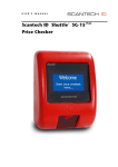
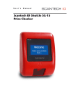
USER’S MANUAL Scantech ID Shuttle+ SG-15 PLUS Price Checker User’s, Installation and Configuration Manual + Plus Scantech-ID Shuttle SG-15 Copyright © 2009, Scantech-ID BV. This manual is copyrighted, with all rights reserved. Under the copyright laws, this manual may not, in whole or in part, be copied, photocopied, reproduced, translated or converted to any electronic medium or machine readable form without prior written consent of Scantech-ID BV. Limited Warranty Under all circumstances this manual should be read attentively, before installing and/or using the product. In no event shall Scantech-ID BV be liable for any direct, indirect, special, consequential or incidental damages arising out of the use or inability to use this documentation or product, even if advised of the possibility of such damages. In particular, Scantech-ID BV shall not be liable for any hardware, software, or data that is stored or used with the product, including the cost of repairing, replacing or recovering the above. Scantech-ID BV reserves the right to change parts of the device at any time without preceding or direct announcement to the client. Scantech-ID BV reserves the right to revise this manual, and to make changes in the contents without obligation to notify any person or entity of the revision or change. A serial number appears on the product. Make sure that this official registration number has not been removed. It should be used whenever servicing by Scantech-ID BV or an authorised Scantech dealer is necessary. Important This equipment has been tested and found to comply with the limits for a Class B digital device, pursuant to EN55022, and with the limits for a class A digital device, pursuant to part 15 of the FCC rules. These limits are designed to provide reasonable protection against harmful interference when the equipment is operated in a commercial environment. This equipment generates, uses, and can radiate radio frequency energy and, if not installed and used in accordance with the user’s manual, may cause harmful interference to radio communications. Operation of the equipment in a residential area is likely to cause harmful interference in which case the user will be required to correct the interference at his own expense. Any unauthorised changes or modifications to this equipment could void the user’s authority to operate this equipment. + The Shuttle is in conformity with the CE standards. Please note that a Scantech CE-marked power supply unit should be used to conform to these standards. Radio and television interference Operation of this equipment in a residential area can cause interference with radio or television reception. This can be determined by turning the equipment off and on. The user is encouraged to try to correct the interference by one or more of the following measures: • Re-orientate the receiving antenna • Relocate the devices with respect to the receiver • Move the device away from the receiver • Plug the device into a different outlet in order to have the device and receiver on different branch circuits If necessary, the user should consult the manufacturer, an authorised Scantech dealer or experienced radio/television technician for additional suggestions. The booklet "How to Identify and Resolve Radio-TV Interference Problems", prepared by the Federal Communications Commission, can be of help. It can be obtained from the U.S. Government Printing Office, Washington, DC 20402, Stock No. 004000003454. P/N A3720011 V2.00 18-08-2009 1 Table of contents Table of contents ......................................................................................... 1 Preface ................................................................................................. 3 Chapter 1 Product Safety ........................................................................... 4 1.1 Used conventions ............................................................. 5 1.2 Laser safety..................................................................... 5 1.3 Declaration of Conformity ................................................. 8 1.4 Scanner Labelling............................................................. 9 Chapter 2 General Description .................................................................. 10 2.1 Use of the Shuttle+ ......................................................... 11 2.2 Construction of the Shuttle+ ............................................. 12 2.3 Functioning of the Shuttle+............................................... 13 2.4 Power Over Ethernet (PoE) .............................................. 15 Chapter 3 Installation of the Shuttle+ .......................................................... 16 3.1 Unpacking ..................................................................... 17 3.2 Mounting ....................................................................... 17 Chapter 4 System Integration.................................................................... 19 4.1 Software........................................................................ 20 4.2 How to communicate? A Simple example.......................... 23 Chapter 5 Configuring the Shuttle+ ............................................................. 25 5.1 Preface ......................................................................... 26 5.2 Starting the configuration................................................ 28 Preface 2 5.3 Configuration tool network settings .................................. 30 5.4 Scanning the network...................................................... 31 5.5 Configuring the Shuttle+ ................................................... 32 5.6 Network configuration ..................................................... 35 5.7 Wireless configuration ..................................................... 36 5.8 Modifying internal messages............................................ 37 5.9 Miscellaneous settings .................................................... 39 5.10 Cloning settings.............................................................. 40 Chapter 6 Maintaining the Shuttle+.............................................................. 41 6.1 Cleaning......................................................................... 42 Appendices ............................................................................................... 43 A Connector types and pin definitions .................................. 45 B Controlling the display and Shuttle+ terminal...................... 47 C Character sets................................................................ 53 D Factory Default Settings .................................................. 55 E Upgrading Firmware........................................................ 57 F Barcode set up (omni directional scanner) ........................ 59 G Frequently Asked Questions............................................. 65 H Shuttle+ Project tasks...................................................... 69 I Technical specifications................................................... 71 J Overview Partnumbers .................................................... 73 K Shuttle+ Demonstration program ...................................... 74 L 802.11 B/G/N mini-PCI cards .......................................... 76 M Network/WIFI LED's and Dipswitches................................ 77 Preface The Shuttle+ is an entry level, small and attractive Price Checker. The Shuttle+ features the latest technology. Interfacing is done either through Wireless RF or hard wired Ethernet. The bright display has, depending on the font set, 3 or 5 lines and can display up to 20 characters per line. There is a choice of bar code scanners between the low cost single scan line CCD scanner or the high performance 20 scan lines laser scanner. Because of its size and the sympathetic good looks the Shuttle+ can be installed anywhere in a store, including on the shelves. This flexibility of installation is enhanced by the optional Power-over-Ethernet. The three available standard colours also greatly help to fit most interiors. General Information The Scantech-ID Shuttle+ is the latest product developed by the company that has more than 15 years of experience in the field of customer information systems. Today we offer a choice of scanner (CCD single line or laser 20 omni directional lines), a choice of colour (Silver, Black or Red) and a choice of interface (WiFi or LAN). Quality and Durability The Shuttle+ comes with the same top quality as all other Scantech-ID products. So at a very competitive price the same quality and performance of more expensive products is available. Due to the high MTBF times of every component a long and service free operation time is secured. Flexibility The size of 182mm (height), 131mm (width) and 95mm (depth), makes the Scantech-ID Shuttle+ small enough to be installed in larger numbers per store. Even when mounted on a shelf it will not block products on display. The bright display makes it easy to read prices and product information. Connectivity The Shuttle+ comes standard with a Configuration Tool (MS-Windows). A customized application program -not supplied by Scantech-ID- is necessary for retailers to operate the SG-15Plus in their specific environment. Scantech supplies software source code examples plus Ethernet drivers for easy integration. Chapter 1 Product Safety + Scantech-ID Shuttle SG-15 1.1 Plus USED CONVENTIONS In this manual the following conventions are used: ATTENTION Gives a tip, an instruction or a point of attention. IMPORTANT Warns for possible damage to the scanner or other objects when not following an instruction. DANGER! Warns for possible harm to persons when not following an instruction. 1.2 LASER SAFETY ATTENTION During installing, always follow the instructions. DANGER! Do not stare into the laser beam. The laser safety is in conformity with IEC 825 and 21CFR140. 5 6 Product Safety German: + Der Strichcode-Scanner SHUTTLE entspricht den Sicherheitsvorschriften nach IEC 825-1 (1993) für ein Laserprodukt der Klasse I. Er entspricht auch U.S. 21CFR1040, anwendbar auf ein Laserprodukt der Klasse IIa. Vermeiden Sie langzeitiges Hineinblicken in direktes Laserlicht. Dutch: + De SHUTTLE scanner voldoet aan de veiligheidsnormen IEC 825-1 (1993) voor een Klasse I laserproduct. Tevens voldoet de scanner aan U.S. 21CFR1040, van toepassing op een Klasse IIa laserproduct. Vermijd langdurig kijken in direct laserlicht. French: + Le scanner SHUTTLE est conforme aux normes de sécurité IEC 825-1 (1993) s’appliquant à un produit laser de la classe I. Il est également conforme à la U.S. 21CFR1040 telle qu’elle s’applique à un produit laser de la classe IIa. Eviter de rester exposé longtemps à la lumière directe du laser. Danish: + SHUTTLE skanneren er i overensstemmelse med sikkerhedsstandarden IEC 825-1 (1993) for laserprodukter i klasse I. Den er også i overensstemmelse med U.S. 21CFR1040, der gælder for laserprodukter i klasse IIa. Undgå at se direkte på laserlys i længere perioder.. Finnish: + SHUTTLE -skanneri täyttää luokan I lasertuotteelle IEC 825-1:ssä (1993) asetetut turvavaatimukset. Se täyttää myös U.S. 21CFR1040:ssa asetetut vaatimukset siltä osin kuin ne koskevat luokan IIa lasertuotetta. Vältä pitkäaikaista suoraan laservaloon katsomista. Swedish: + Avsökaren SHUTTLE uppfyller säkerhetsnormen IEC 825-1 (1993) för laserprodukter av klass 1. Den uppfyller dessutom U.S. 21CFR1040 som gäller för laserprodukter av klass IIa. Undvik att titta i direkt laserljus under längre perioder. Norwegian: + SHUTTLE skanneren er i samsvar med sikkerhetsstandarden IEC 825-1 (1993) for laserprodukter i klasse I. Den er også i samvar med U.S. 21CFR1040 for laserprodukter i klasse IIa. Unngå å se langvarig på direkte laserlys. Italian: + Lo scanner SHUTTLE è conforme alle norme di sicurezza IEC 825-1 (1993) relative ad un prodotto laser di Classe 1. È inoltre conforme alla norma U.S. 21CFR1040 relativa ad un prodotto laser di Classe IIa. Evitare l'esposizione prolungata all'emissione diretta di luce laser. Portuguese: + O scanner SHUTTLE está conforme as normas de segurança IEC 825-1 (1993) para a Classe 1 dos produtos laser. Também está conforme a norma U.S. 21CFR1040 aplicada nos produtos laser da Classe IIa. Evite expor os olhos directa e prolongadamente aos raios laser. + Scantech-ID Shuttle SG-15 Plus 7 Spanish: + El scanner SHUTTLE reune las normas de seguridad IEC 825-1 (1993) para un producto laser de Clase 1. Y también reune las normas U.S. 21CFR1040 que se aplican a un producto laser de Clase IIa. Se debe evitar mirar muy fijo en luz lasérica directa. English: + The SHUTTLE scanner complies with safety standard IEC 825-1 (1993) for a Class I laser product. It also complies with U.S. 21CFR1040 as applicable to a Class IIa laser product. Avoid long term viewing of direct laser light. Optical: The use of optical instruments with this product will increase eye hazard. Optical instruments include binoculars, microscopes and magnifying glasses but do not include eyeglasses worn by the user. Radiant Energy: + The SHUTTLE uses a low-power laser diode operating at 630…670 nm in an opto-mechanical scanner resulting in less than 0.6 mW peak output power. Laser light observed at 13 cm (5.1 in.) above the window through a 7 mm (0.28 in.) aperture and averaged over 1000 seconds is less than 3.9 µW per CDRH Class IIa specification. Do not attempt to remove the protective housing of the scanner, as unscanned laser light with a peak output up to 0.8 mW could be accessible inside. Laser Light Viewer: The scanner window is the only aperture through which laser light may be observed on this product. A failure of the scanner motor, while the laser diode continues to emit a laser beam, may cause emission levels to exceed those for safe operation. The scanner has safeguards to prevent this occurrence. If, however, a stationary laser beam is emitted, the failing scanner should be disconnected from its power source immediately. Adjustments: Do not attempt any adjustments to or alteration of this product. Do not remove the scanner’s protective housing. There are no user-serviceable parts inside. CAUTION Use of controls or adjustments or performance of procedures other than those specified herein may result in hazardous laser light exposure. 8 1.3 Product Safety DECLARATION OF CONFORMITY + Scantech-ID Shuttle SG-15 1.4 Plus SCANNER LABELLING 9 Chapter 2 General Description + Scantech-ID Shuttle SG-15 2.1 Plus 11 USE OF THE SHUTTLE+ The Shuttle+ is a Price Checker, which provides the user with the opportunity to scan their chosen product and display product information or verify the price before getting to the checkout. Apart from this, the Shuttle+ offers the ability to interface with loyalty cards, display special offers, display dual currency, etc. Moreover, store level profitability can be increased. Apart from the use as an advanced price checker, the Shuttle+ can also be used in many other environments where identification and information is required. This includes use with ticketing, access control, time check, route and place guidance and item check in a warehouse or stockroom. 12 General Description 2.2 CONSTRUCTION OF THE SHUTTLE+ SG-15PLUS The various parts of the Shuttle+ are indicated in figure 2.1: A. Front housing with window B. LCD The display size is 128x64 pixels The display features white characters on a blue backlight background C. Main board, PoE add-on PCB (optional) or mini-PCI card (optional) D. Scantech omni-directional scanner or CCD single line scanner E. Back Housing F. Back Plate F E C D B A Fig 2.1 + Scantech-ID Shuttle SG-15 2.3 Plus 13 FUNCTIONING OF THE SHUTTLE+ SG-15PLUS 2.3.1 Introduction The Shuttle+ is an information terminal, which receives input (barcode), from a user and answers via the display. The display contents is provided by a computer application, which runs on a (server) system elsewhere. 2.3.2 Input The main input -bar code information- is generated by the integrated Scantech barcode reader, which is characterised by a high performance 20 scan line omni-directional laser scan pattern, or by a CCD single line scanner. 2.3.3 Output Based on the bar code input and the application software on the host-system the Shuttle+ communicates with the user via text on the screen and optional graphics and audio feedback via the speaker. 14 General Description 2.3.4 Software & Control The functions during daily use of the Shuttle+ are determined by the application program, which is controlling the Shuttle+. So the task of the storage of databases, providing the information and sending it to the display of the Shuttle+ will be performed by a central host system. Providing this application, running on the host system, is the responsibility of the System Integrator. Host + Shuttle barcode Database barcode Application (by System Product and graphical info Integrator) Product info The SG-15Plus sends barcodes to the host, according to the following table: CODE MESSAGE FORMAT EAN-13 F D1 D2 D3 D4 D5 D6 D7 D8 D9 D10 D11 D12 D13 [CR] EAN-8 FF D1 D2 D3 D4 D5 D6 D7 D8 [CR] UPC-A A D1 D2 D3 D4 D5 D6 D7 D8 D9 D10 D11 D12 [CR] UPC-E E Ø [CR] ITF i D1 - Dx [CR] Code 39 * D1 - Dx [CR] Code 32 * D1 - Dx [CR] Codabar % D1 - Dx [CR] Code128 # D1 - Dx [CR] EAN-128 P ]C1 D1 - Dx [CR] DataBar R D1 - Dx [CR] D1 D2 D3 D4 D5 D6 Note: The message format is bar code programmable with the Scantech Configuration Guide. The Shuttle+ documentation and the demo/set-up programs provide you with all the required information on how to communicate with the Shuttle+ and how to control it. The SG-15Plus Product Support CD contains all kind of source code examples and a complete example for application software (incl. free source code), including an Ethernet driver to enable the integrator to get the SG-15Plus up and running in no time. + Scantech-ID Shuttle SG-15 2.4 Plus 15 POWER OVER ETHERNET (POE) The alternative for powering the Shuttle+ through an external PSU (adapter), is using the Power-Over-Ethernet (PoE) version of the SG-15Plus. In this way the SG-15Plus is powered directly through the Ethernet and you don’t need to install a (230/110VAC) mains socket anymore somewhere in the middle of the store, so in this way saving you quite some installation costs! The Shuttle+ PoE complies with the official standard: IEEE 802.3af. For your information: PoE uses either the 4 Ethernet data lines (pin 1,2,3,6), called End-Span, or the not used Ethernet lines (pin 4,5,7,8), called Mid-Span, to transport the DC voltage to the SG-15Plus. Which method is used, depends on the supplying powered network switch (hub). The Shuttle+ supports both methods automatically. See also Appendix A. Towards the host-side, this means that you need a special hub/router which supports the Power-Over-Ethernet (PoE) feature following the official standard for this: IEEE 802.3af. To avoid any miscommunication in this area: Scantech does not supply network components like a power injector, network cabling, powered hubs etc. When we ship the first unit(s) SG-15Plus PoE in the current stage, this is in most cases for demo- or evaluation purposes. Therefore we DO include the standard PSU. This is done ‘just to be sure’ and to give our customers the possibility to at least turn-on the SG-15Plus independent from the hub, for instance for SG-15Plus configuration purposes. Of course, for the real installation in the store (roll-out), with the SG-15Plus connected to a hub with Power-Over-Ethernet IEEE 802.3af, you do not need the mains PSU (adapter). In case a project roll-out starts, we will not include the mains PSU anymore. Physically (i.e. inside the SG-15Plus) this means that we place a special PoE board to support the PoE feature. See Appendix J for SG-15Plus POE Partnumbers. 16 Installation + Plus Chapter 3 Installation of the Shuttle SG-15 + Scantech-ID Shuttle SG-15 3.1 Plus 17 UNPACKING Unpack the Shuttle+ as follows: 1. Take the Shuttle+ and its accessories out of the box. 2. Remove the packing material. 3. Check the packing list to make sure you have received all of the items ordered. 4. Visually inspect the Shuttle+ and accessories for any evidence of physical damage. 5. If anything is missing or appears to be damaged, immediately contact your dealer. ATTENTION Store the packing material and boxes: it should be used whenever the Shuttle+ is transported for servicing. 3.2 MOUNTING Once you have unpacked all components, you can start installing the Shuttle+. Installing the Shuttle+ is divided in two steps: 1. Mounting the Shuttle+ to the wall. 2. Installation is discussed in detail on the following page. 18 Installation B A A fig 3.1 ATTENTION Mount the Shuttle+ on a height for convenient view of the display. 1. Mark the locations for the mounting holes on the wall and drill two holes. 2. Put plugs in the holes. 3. Connect the power cable and the communication cable of the Shuttle+ (see figure 3.1 above). 4. Fasten the Shuttle+ to the wall by clicking it on the 2 screws (parkers, indicated by A). 5. If necessary, adjust the contrast of the display by trimming the regulator through the small hole on the side, with a small screwdriver (indicated by B). + Scantech-ID Shuttle SG-15 Plus Chapter 4 System Integration 19 20 4.1 System Integration SOFTWARE The Shuttle+ is a thin-client, front-end Price Checker. Its behavior is very easily configurable and fully determined by the software package, driving the Shuttle+ from the Back-Office/server. This software package (or: added value) will be supplied by the System Integrator. This is because of the fact that there are no set international standards with regard to product database structures and/or programming languages. Furthermore it is not Scantech´s primary role to supply end-user application software. ATTENTION The SG-15Plus Product Support CD contains a framework of software tools which includes an Ethernet driver and a complete demo application (including free of charge source code). This makes it very easy to create a server application in no time at all. These objects are available for both Windows and Linux See CD \Source Code Examples\Enhanced 4.1.1 Software functionality The global function of the Shuttle+ software package, running on the Back-Office/server, is: 1. Set-up and maintain communication between the application itself and the Shuttle+ terminal(s). 2. Provide product information (e.g. article name and price) from the store’s database, combined with the right font size and layout. 3. Diagnostics & Terminal Statistics (optional). + Scantech-ID Shuttle SG-15 Plus 21 4.1.2 Scantech Tools and Drivers In order to support our System Integrators in the best possible way, Scantech ID supplies: 1. Extensive documentation describing all details of the product. (this manual and more). 2. Configuration utility: See chapter 5. Scantech ID provides this Configuration Tool, which only runs under Microsoft Windows (all versions). This tool makes it possible to configure an SG-15Plus anywhere in the network, having any possible IP-Address. ATTENTION The SG-15Plus runs an embedded web server for configuration purposes. This makes it possible to configure an SG-15Plus with any internet browser, using any operating system, without the need of a dedicated configuration utility. 3. Examples of source code: See CD-ROM \Source Code Examples. All these items can be found on the Shuttle+ Product Support CD-ROM. 22 System Integration 4.1.3 Compatibility The SG-15Plus is a basic Price Checker, so it does not require an advanced and extensive set of commands to control it, compared it to our other model(s). In other words: The SG-15Plus is not backward compatible with the SG-20. The main reasons for this are: 1. The difference in layout of the SG-15Plus display: 5 lines when using the small font type or 3 lines using the large font type. 2. To improve the readability of the display, a proportional font type is used, instead of a font type with a fixed character width. About 20 characters per line (max). In case you already created an SG-20 application in the past, you only need to make a few minor changes in order to integrate the Shuttle+; The SG-15Plus uses the same command structure as the SG-20 (using ASCII data and ESC codes). + Scantech-ID Shuttle SG-15 4.2 Plus 23 HOW TO COMMUNICATE? A SIMPLE EXAMPLE The SG-15Plus is a simple IP device in the local network, which accepts and displays normal ASCII characters. After scanning a bar code, it outputs it as a normal ASCII string. The easiest way to communicate with an SG-15Plus right out of the box, without any further configuration, is using a telnet session: 1 First, connect the SG-15plus to your network (using a normal 1:1 Ethernet cable) or directly to your PC (using a crossed Ethernet cable). 2 As you turn on the SG-15Plus, the 'Offline' message will flash on the display. It will continue to do so, until you've made a software connection to it. 3 By default, the SG-15Plus is configured as TCP Server, having the IP address 192.168.3.227 and listening to port 9101. 4 Make sure that your PC has an IP address in the same IP range, e.g. 192.168.3.32. 5 You should be able to 'ping' the SG-15Plus now, by entering: Ping 192.168.3.227 If it's not successful, you should double check the IP address of your PC and all cable connections. Also, make sure the SG-15Plus is configured to it's default settings. You can force this as described in Appendix D. 24 6 System Integration You need a client program to connect to the SG-15Plus. The widely used 'telnet' program is such a program. You can connect to the SG-15Plus by entering: telnet 192.168.3.227 9101 As a result, the 'Offline' message on the SG-15Plus will disappear. 7 Now you can enter characters on your keyboard, which should appear on the SG-15Plus display. Also, when you scan a barcode with the SG-15Plus, it should appear on your monitor. 8. See appendix B for more tweaks, tips and tricks with the SG-15Plus display. Some notes: 1. Regarding the Network Connection Properties of your PC: You may have to turn OFF DHCP and make sure the IP address of your PC is in the same IP range as the Shuttle+ you want to communicate with. For instance by giving your PC IP address: 192.168.3.32 2. If you have a firewall running on your PC, make sure it's not blocking the communication in any way. + Scantech-ID Shuttle SG-15 Plus 25 + Chapter 5 Configuring the Shuttle + 26 5.1 Configuring the Shuttle PREFACE There are two methods to configure a Shuttle+: 1. Using a web browser. The SG-15Plus has an internal web server for configuration purposes. This eliminates the need for a dedicated configuration tool and makes it possible to configure a Shuttle+ independent of the operating system on your system. Just start any web browser and enter the IP-address of your Shuttle+. 2. Using the Configuration Tool, supplied by Scantech ID. Scantech ID provides this Configuration Tool, to be able to configure a Shuttle+ anywhere in the network, having any possible IP-Address. The Shuttle+ uses a special package format, communicating through UDP, for it's configuration. This utility makes use of this format. (The recordlayout can be made available to customers to write their own configuration tools, if desired). ATTENTION The Configuration Tool only runs on MS-Windows. In the near future, a version for Linux will also be available. + Scantech-ID Shuttle SG-15 Plus 27 Because the Shuttle+ communicates through 10/100BaseT Ethernet (10/100Mbit) or 802.11 B/G/N WiFi, you need access to your local network (and connect the SG-15Plus to it also) for configuration purposes. IMPORTANT: FIREWALLS You may have to modify the firewall settings of your system for the Configuration Tool to run flawlessly. IMPORTANT: IP ADDRESSES In order to communicate with a Shuttle+ through a web browser or to update firmware through tftp (or using the firmware upload feature of the Configuration Tool), make sure the IP-address of your system is in the same subnet as the Shuttle+. + 28 5.2 5.2.1 Configuring the Shuttle STARTING THE CONFIGURATION Configuration using a web browser Make sure your computer is in the same IP subnet as the Shuttle+ you're going to configure. E.g.: The Shuttle+ has IP address 192.168.3.227 and your computer has address 192.168.3.1. Start your web browser, Enter the IP address of the Shuttle+ and the following screen should open: The login password is default blank. Using the web browser, you can alter the same settings of the Shuttle+ as with the Configuration Tool. See paragraphs 5.6 - 5.9 for more explanation. + Scantech-ID Shuttle SG-15 5.2.2 Plus 29 Configuration using the Configuration Utility Locate the utility, SG-15Config.exe, on your computer or CD and start it up. The following screen should appear: Note that the version of this program may differ from the one you have. Please check the Scantech-ID website for the latest version. The Shuttle+ requires Configuration Tool Version 4.0 or higher. With this tool version (4.0) you are also able to configure the first version of the SG-15. + 30 Configuring the Shuttle 5.3 CONFIGURATION TOOL NETWORK SETTINGS on In order to select the appropriate Ethernet adapter on your system, click on the 'down arrow' in the main screen to enter the settings screen of the Configuration Tool. This will open the following window: If your system has more than one Ethernet adapter (or WLAN adapters) active, you can use the button "Next>>>" to scroll through the available adapters. This program will use the selected adapter to communicate with the Shuttle+(s). The option to select a specific UDP Port to communicate with, could be of use in combination with firewalls or other network protection software. + Scantech-ID Shuttle SG-15 Plus 31 5.4 SCANNING THE NETWORK This utility is able to scan your entire local network and find any SG-15Plus, having any IP Address. Just hit the button "SCAN" and it will start scanning for 15 seconds. IMPORTANT While scanning, the "SCAN" button turns into "STOP", so you can stop the scan at anytime. The list will be filled with every SG-15Plus which has been found. If you already know that all units have been found, you can hit the "STOP" button, so you don't have to wait for the entire scan to finish. Example: + 32 Configuring the Shuttle 5.5 CONFIGURING THE SG-15PLUS Select one SG-15Plus from the list and hit the "CONFIGURE" button. The following screen appears: 5.5.1 5.5.2 5.5.3 The screen is divided into 3 sections: 5.5.1 General Information. On the left side of the screen, you’ll see some characteristics of this specific SG-15Plus. IP Address The IP Address is the actual IP Address which the SG-15Plus is using right now; this can differ from the IP Address field on the "Network" tab page, if DHCP is used. + Scantech-ID Shuttle SG-15 Plus 33 MAC Address The MAC Address which the SG-15Plus uses. This can be the Scantech-ID vendor address (00-13-b7-xx-xx-xx) or the address from the mini-PCI card. Firmware Version and Date The version and release date from the running firmware. Active Interface The interface which the SG-15Plus is using: 100BaseT or Wireless 802.11 B/G/N. Dipswitch 1 If active, then the SG-15Plus loads it's default settings during startup. See appendix D. Dipswitch 2 If active, then the SG-15Plus chooses the 100BaseT wired Ethernet interface at all times, even if a mini-PCI card is placed. See 5.7. + 34 Configuring the Shuttle 5.5.2 Configuration tab pages. See chapters 5.6 - 5.10 for a description. 5.5.3 Action buttons: Clone Copies all settings (except the own IP Address) of the currently selected SG-15Plus, for later use. If an SG-15Plus is "Cloned", its entry in the list on the main screen (see section 5.4) is turned green to indicate which one you're "Cloning". Paste Paste settings of a previous "Cloned" SG-15Plus, to the currently selected SG-15Plus. Load from File Load a file, containing previous saved settings. Save to File Save all settings (except the own IP Address) of the currently selected SG-15Plus to a file. Undo All Restores all settings to the moment you entered this screen. Apply Send all settings (all tab pages) to the SG-15Plus. The SG-15Plus should reset after these are received properly. + Scantech-ID Shuttle SG-15 Plus 5.6 NETWORK CONFIGURATION The first tab page called "Network" is activated, as soon as this screen has been opened. You can specify your own specific network settings here. IP Address The unique IP number of that SG-15Plus Subnet Mask Indicates Network group of addresses within which the SG-15 Plus operates. DHCP SG-15 Plus requests and obtains a network address from the server. Default Gateway Node on the network that serves an access point to another network “Escape address” or “Emergency Exit” Not applicable for the SG-15 Plus. Connect Mode UDP Message exchange takes place without confirmation TCP Message exchange with acknowledgement Client SG-15 Plus initiates making connection with server (“makes the call”) Server The BO server initiates connection with SG-15 Plus. Use this mode for the demonstration program (SG15Demo.exe) or with a telnet program. Remote IP Network Address of the Back-Office Server on which the application runs, which controls the SG-15 Plus. 35 + 36 Configuring the Shuttle 5.7 WIRELESS CONFIGURATION The second tab opens the IEEE802.11 B/G/N Wireless settings. This is only applicable if your SG-15plus has a WiFi card built-in of course. You can set your specific 802.11 B/G/N parameters in this screen. Note: by means of the webbrowser, you have access to more WiFi parameters. SWITCHING TO WiFi After setting all Ethernet and WiFi parameters in the correct manner, you find at the back of the SG-15Plus a dipswitch to select the active interface: Wifi switch Ø× ØØ × Ethernet interface active WiFi interface active Set Back To Default at Power-up + Scantech-ID Shuttle SG-15 Plus 37 5.8 MODIFYING INTERNAL MESSAGES The third tab page opens the Internal Messages Settings: 5.8.1 Internal Messages The SG-15Plus has three internal messages: Idle Message This message is displayed during idle mode: The default screen which is shown when the SG-15Plus has nothing to do. Error Message This message is displayed as soon as a timeout occurs after scanning a barcode: After scanning a barcode, the SG-15Plus waits for the remote host to return information about the scanned product. If this takes too long (see "Timeout Values"), the Error Message is displayed. + 38 Configuring the Shuttle Offline Message This message is displayed (inverted and flashing) if no connection has been established yet (using connection mode "TCP Client" or "TCP Server", see 5.6). If the connection mode is "UDP", this message will not be displayed at all. All messages can be located anywhere on the screen on any coordinate (horizontal 0-127, vertical 0-63). For easy placement on commonly used positions, an Alignment can be chosen also. Dependent on the alignment which is used, the coordinates are possibly ignored. (E.g. : If the Vertical Alignment is "Center", the Y-coordinate will be ignored). A single line of the message can be displayed in either the Large or Small font size. 5.8.2 Timeout Values The SG-15Plus uses 2 Timeout counters, which are user definable: 1 2 Nr of seconds which text is displayed on the screen (0-15 secs). This includes the following texts: - Internal Messages - Text from a remote host Nr of seconds to wait for data from the remote host, after scanning a barcode (0-15 secs). After this, the error message is displayed. 5.8.3 Character table The SG-15Plus supports multiple codepages (see appendix C). Only 1 codepage can be used at a time. + Scantech-ID Shuttle SG-15 Plus 39 5.9 MISCELLANEOUS SETTINGS The fourth tab contains miscellaneous settings: Barcode scanning You can modify the minimum time to wait between successive scans. This prevents double-scans. Explanation: Normally, after scanning, the internal scanner is disabled until the remote host sends the product description or until a timeout occurs (and the error message is displayed). After that, the barcode scanner is enabled again. On very fast networks, it may occur that the response from the host is received very fast. In fact too fast for the customer to withdraw the product from being scanned again. Increasing the time between successive scans prevents this from happening. + 40 5.10 Configuring the Shuttle CLONING SETTINGS In Chapter 5 was described how to clone the settings of a single SG-15Plus. It's possible to send all these settings to every single connected SG-15Plus at once. This makes it extremely easy to configure all SG-15’s with the same settings, without the hassle of accessing every single SG-15Plus separately. This can be achieved by pressing the 'CLONE ALL' button on the main screen. After this, all units in the list will be configured with the same settings. When an SG-15Plus receives its new settings, it will reboot. IMPORTANT Cloning copies all settings, except the Shuttle+ own IP Address. + Scantech-ID Shuttle SG-15 Plus 41 + Chapter 6 Maintaining the Shuttle 42 Maintaining the Shuttle 6.1 CLEANING The Shuttle+ requires little maintenance. Only occasional cleaning of the scanner window is necessary to remove dirt and fingerprints. Cleaning can be performed during operation with a non-abrasive glass spray cleaner and a soft lint-free cloth. Clean the cover and window of the Shuttle+ every now and then. Take care of the following: • Use a mild glass spray cleaner; • Spray the cleaner on a soft, lint-free cloth; • Wipe the Shuttle+ clean. IMPORTANT • Clean the red window very carefully. It is scratch sensitive. IMPORTANT The exterior of the Shuttle+ should NOT be cleaned with cleaners containing: • Aromatic hydrocarbons • Chloride • Acids, oxidizing agents • Abrasives • Other aggressive cleaners Appendices A Connector types and pin definitions............................................ 45 B Controlling the display and Shuttle+ terminal................................ 47 C Character sets.......................................................................... 53 D Factory Default Settings ............................................................ 55 E Upgrading Firmware.................................................................. 57 F Barcode set up (omni directional scanner) .................................. 59 G Frequently Asked Questions....................................................... 65 H Shuttle+ Project tasks................................................................ 69 I Technical specifications ............................................................ 71 J Overview Partnumbers .............................................................. 73 K Shuttle+ Demonstration program ................................................ 74 L 802.11 B/G/N mini-PCI cards.................................................... 76 M Network/WIFI LED's and Dipswitches ......................................... 77 44 Appendices + Scantech-ID Shuttle SG-15 A Plus 45 PIN DEFINITIONS AND CONNECTOR TYPES Physical Connections Ethernet Connector 1 2 3 6 - Tx+ TxRx+ Rx- Cable between Shuttle+ and network connection: Use a standard, ‘8 pin’, 1-to-1 Ethernet network cable to connect the Shuttle+ to your Ethernet network. IMPORTANT Make sure you apply proper cabling when using the SG-15Plus Power-over- Ethernet version (IEEE802.3af PoE). PoE uses either the 4 data lines (1,2,3,6), called End-Span, OR the not used lines (4,5,7,8), called Mid-Span. Which method is used, depends on the supplying network switch. The Shuttle+ SG-15Plus supports both methods automatically. DC Power connector 1 GND 2 +5.2V 1 2 Front view See fig 1.4 for the physical location of the connectors. 46 Appendices Pin Definition AUX Port *1 *1 PIN SIGNAL DIRECTION 1 RTS output 2 RXD input 3 TXD output 4 CTS input 5 GND 6 +5 VDC *1 output/300mA max + Ref: Shuttle signal • Connector type: RJ-11/14 6pin connector for e.g. AMP 5-554710-1 • The Shuttle+ AUX port is designed for basic RS-232 input like from a hand held scanner. • To connect a Champ HH scanner, please use Scantech cable P/N A280585 • RS-232 communication parameters: 9600 Baud, 8 Data, 1 Stop bit, No Parity, RTS/CTS: OFF, Suffix: <CR> • The hand held scanner needs to transmit the data in the same message format as the integrated scanner. See Chapter 2.3.4 for the default message format. A dedicated programming sheet for the Champ HH scanners is available at Scantech Technical Support. + Scantech-ID Shuttle SG-15 B Plus 47 CONTROLLING THE DISPLAY AND SHUTTLE+ TERMINAL Introduction The SG-15Plus acts a normal remote terminal; Every received ASCII value (between 20 and 255), which isn't part of a command, is normally displayed on the screen. Furthermore, the Shuttle+ is controllable and easily configurable by means of ESC (Escape) commands to customize the following parameters; • Cursor Control • Clearing the Display • Aligning Text • You can remotely turn OFF and ON the Shuttle+ from the Back-Office application. "SG-15 Plus The Green Price Checker" . It is strongly recommended to use this feature, during the stores’ closing hours and when the article database is not available. It will save energy, extend the lifetime of the Shuttle+ and shows a better system design. Due to the fact that the SG-15Plus uses proportional fonts (every single character has it's own specific width), you never know precisely how much characters fit on one line. Therefore, when a character doesn't fit on the current line, it's not displayed at all (instead of printing it on the next line, which gives undesired "messy" results) You can move to another line by sending a Carriage Return (0x0d), or a Linefeed (0x0a). Both have the same effect: Going to the start position of the next line). You can move the cursor by sending: - 'Set cursor' command (ESC 0x27), for predefined cursor positions. - 'Set Pixel Position' command (ESC 0x2C), for placing the cursor on any pixel location. For easy alignment of text on often desired positions (like the center of the screen, right of the screen, bottom of the screen, etc) you can use the 'Align text' (ESC 0x2e) command. 48 Appendices At the end of this Appendix you find the complete command set, including the sub-parameters. On the next pages, you find some examples to give an impression of the way you can use the display of the SG-15Plus. These examples are also shown when using the -simple- demo program SG15Demo.exe. See CD and Appendix K. Note: <ESC> should be sent as the hexadecimal value 1B. Note: The notation of e.g. 0x24 means the hexadecimal value 24. Example 1 How to create this screen: COMMAND or data string COMMENT <ESC> 0x42 0x30 Font size 0 <ESC> 0x25 Clear the screen, cursor top left "Mineral water" Text 0x0d Carriage Return = Next line "1 Ltr." Print text <ESC> 0x42 0x31 Font size 1 <ESC> 0x2e 0x38 "€ 0.98" 0x03 Align text to right bottom + Scantech-ID Shuttle SG-15 Plus 49 Example 2 How to create this screen: COMMAND or data string COMMENT <ESC> 0x42 0x30 Font size 0 <ESC> 0x25 Clear the screen, cursor top left <ESC> 0x2e 0x31 "Coca Cola 0.33Ltr" 0x03 Align text to center - top <ESC> 0x2c 0x30 0x45 Set cursor to pixel position (0,21) <ESC> 0x2e 0x3a "€2.69 (Crate)" 0x03 Align text to horizontal center <ESC> 0x42 0x31 Font size 1 <ESC> 0x2e 0x37 "Special Offer !" 0x03 Align text to bottom center 50 Appendices Example 3 How to create this screen: COMMAND or data string COMMENT <ESC> 0x42 0x30 Font size 0 <ESC> 0x25 Clear the screen, cursor top left <ESC> 0x2e 0x30 "Winner" 0x03 Align text to left - top <ESC> 0x2e 0x32 "Winner" 0x03 Align text to right - top <ESC> 0x2e 0x36 "Winner" 0x03 Align text to left - bottom <ESC> 0x2e 0x38 "Winner" 0x03 Align text to right - bottom <ESC> 0x42 0x31 Font size 1 <ESC> 0x2e 0x34 "You Win!" 0x03 Align text to center + Scantech-ID Shuttle SG-15 Plus 51 SG-15 Command Set V2.0 This command set refers to SG15plus firmware version 3.03 and higher. COM MAND ESC (1B)16 SUBCOMMAND DESCRIPTION PARAMETERS HEX DEC ESC ESC 24 25 36 37 $ % reserved ESC 27 39 ' <POS> Set Cursor Position 0x30-0x3F Set the cursor position on the display. Note : The actual pixelposition depends on the currently selected font set: Every x-position is a multiple of 8 pixels. Every y-position depends on the currently selected font set (height of 12 or 21 pixels) Clear Display Clear the Display and move the cursor to the topleft position <LINE> 0x30-0x34 Pos : 0 - 15 (0x30 - 0x3F) Line : 0 - 4 (0x30 - 0x34) ESC 2C 44 , Set Pixel Position Set the current pixel position on the display. This allows a text to be printed anywhere on the display. <POS> 0x30-0xAF <LINE> 0x30-0x6F <ALIGN> 0x30-0x3E <DATA> "…" [0x03] Pos : 0 - 127 (0x30 - 0xAF) Line : 0 - 63 (0x30 - 0x6F) Note : A character will only be displayed on the current coordinates if it fully fits on the screen. ESC 2E 46 . Align a string of text Print a text, using the current font set, on a calculated postion on the screen. <Align> can be one of the following values: 0x30 - Left Top 0x31 - Center Top 0x32 - Right Top 0x33 - Left Center 0x34 - Center Center 0x35 - Right Center 0x36 - Left Bottom 0x37 - Center Bottom 0x38 - Right Bottom 0x39 - Left, using current y-coordinate 0x3A - Center, using current y-coordinate 0x3B - Right, using current y-coordinate 0x3C - Top, using current x-coordinate 0x3D - Center, using current x-coordinate 0x3E - Bottom, using current x-coordinate <Data> This field has a maximum length of 75 characters. Use 0x03 (ETX) as last char, if less characters are used. 52 ESC Appendices 40 64 @ Sleep Clear display and Turn off Laser, Motor and Backlight. plus ESC 41 65 A ESC 42 66 B SG15 keeps functioning as normal. Wake Up Return from sleep Select Font Set plus The SG15 has 2 internal font sets: 0x30 - Font set 1 (Normal sized font) 0x31 - Font set 2 (Large font) ESC 58 88 X Show GIF Displays a GIF on the screen. GIFs and Text can be combined on one screen. The GIF can either be animated or static. Image#1 is the same image as used for the Idle screen. <FONTSET> 0x30-0x31 <IMAGE> 0x31-0x34. A displayed image will be cleared after THold seconds (see Manual) GIFs should be uploaded using tftp. Example: Upload file "image.gif" to image position 2: "tftp -i 192.168.3.227 put image.gif /gif2" ESC 5A 90 Z Reset Soft reset ESC 5B 91 [ Enable/Disable scanning Enable or disable barcode scanning ESC 5C 92 \ Enable/Disable Backlight The backlight will be turned on or off ESC 5D 93 ] ESC 5E 94 ^ Sleep/Wakeup internal barcode scanner Put the internal barcode scanner into sleep (turn off laser and motor), or wake it up Beep The internal speaker will generate the default 'beep'. ESC 60 96 ` Get Firmware Version The SG15 ESC 70 112 p plus returns the current firmware version. Format "SG15Vnn.nn" Reroute Ethernet/WLAN communication Can be used to directly communicate with devices on a serial port. Normally, the data is printed on the display. plus ESC 7C 124 | <MODE> 0x30=disable 0x31=enable <MODE> 0x30=off 0x31=on <MODE> 0x30=sleep 0x31=wakeup The SG15 will respond by sending an 'ACK' (0x06) back to the host. Only for Exit/Entry Gate Terminal use (special hardware configuration). The galvanic isolated switch will be closed during 500 milliseconds. The physical connection is available at the back of the special SG15. The SG15 plus will respond by sending an 'ACK' (0x06) back to the host. All not mentioned commands are reserved for possible future use. Do not implement these in your application. <Destination> 0x30 = Display 0x31 = Ser.Port 1 + Scantech-ID Shuttle SG-15 C Plus 53 CHARACTER SETS The SG-15Plus contains 12 character sets: - 0437 0852 0857 0866 0874 1251 1252 1256 1257 GB2312 BIG5 UTF-8 Classic IBM US DOS Latin-2 Central Europe Turkey Cyrillic II DOS Thailand Cyrillic Latin-1 Win Western Arabic Baltic Simplified Chinese Traditional Chinese Unicode (default) Only 1 codepage can be used at a time (see chapter 5.8). Each character set (codepage) is available in 2 sizes (see "ESC B" command). The selection is done with the Configuration Tool or browser under Miscellaneous. Code page 852 (Latin-2) Code page 866 (Cyrillic DOS) 54 Appendices Codepage 874 (Thai) Codepage 1251 (Cyrillic) Codepage 1252 (Latin-1) Codepage 1257 (Baltic) + Scantech-ID Shuttle SG-15 D Plus 55 FACTORY DEFAULT SETTINGS The SG-15Plus can be returned to its default settings, by placing the left dipswitch in the upper position and turn on the power. Once the SG-15Plus has started up, you should disconnect the power again and set the left dipswitch in the lower position. Otherwise the SG-15Plus keeps returning to defaults at every reboot... Back of the SG-15Plus: Wifi Default LAN AUX DC SG-15plus Dipswitch function: Ø× ØØ × Ethernet interface active WiFi interface active Set Back To Default at Power-up 56 Appendices Currently, the Factory Default Settings are as follows: IP Address 192.168.3.227 Subnet mask 255.255.255.0 Default Gateway 192.168.3.250 IP Address Remote Host 192.168.3.32 DHCP Disabled TCP Port 9101 UDP Port 9000 Baudrate internal scanner 9600 Minimal Scanning interval 500 mSec Connect Mode TCP Server Wait for host after scanning barcode 3 seconds Display Message Timeout 5 seconds Font codepage UTF-8 Device Name SHUTTLE+ WiFi mode Infrastructure WiFi AdHoc channel 1 WiFi WEP key 0000000000000 WiFi SSID pegasus WiFi Authentication open/none Bar Code Symbologies active EAN-13, EAN-8, UPC-A, UPC-E (Unicode Transformation Format) (omni-directional scanner) IMPORTANT The user definable texts aren't affected by this action. E UPGRADING FIRMWARE The SG-15Plus firmware can very simply be upgraded by using TFTP. You simply need to obtain a proper firmware file from Scantech ID and upload it using the following command line: E.g. tftp.exe -i 192.168.3.227 PUT firmware.bin / The syntax for a firmware upgrade under LINUX is: E.g. tftp -m binary 192.168.3.227 -c put firmware.bin / Don't forget the "/" at the end ! Of course, the IP address and firmware file may differ... Make sure that the own and remote IP addressing inside SG-15Plus are correct. Upgrading the Shuttle+ usually will be finished in a few seconds. After that, it takes a few seconds for the SG-15Plus to re-flash its memory and to reboot. You can also hit the 'FIRMWARE' button on the main screen of the SG-15Plus Configuration Utility, which starts tftp on the background. Just make sure the TFTP.EXE program is located in your file path. A firmware upgrade can also be carried out by using the web-interface. IMPORTANT It's possible that some of the SG-15Plus settings will return to the default value, when upgrading to new firmware. This depends on the new firmware version, but also on the currently used version. Therefore, you should always check the SG-15's settings when the firmware update is completed. 58 Appendices + Scantech-ID Shuttle SG-15 F Plus 59 BARCODE SET UP (OMNI DIRECTIONAL SCANNER) To change the parameters of the internal scanner, follow the flow-chart shown in this section. Note: Only valid for the omni directional scanner. Start Open scanner programming mode: CODE 1.1 No Change settings by scanning bar codes Finished? Yes Close scanner programming mode: CODE 1.1 END Procedure for programming with bar codes. Close programming mode without updating: CODE 1.2 60 Appendices Bar Codes To Program the Omni-directional Scanner Open Programming Mode and close (with update) 1.1 SG-15Plus omni-scanner macro settings: This macro programming bar code will set the following scanner parameters in one stroke: Serial settings: 9600, 8, n, 1, no handshaking Beeper: Off Sleep mode: Off Postamble: CR Code ID= On, see Chapter 2.3.4 for ID format Scanner LED's: Off Exit programming mode without update 1.2 + Scantech-ID Shuttle SG-15 Plus EAN/UPC On Code 128/EAN 128 On Code 39 On 61 EAN/UPC + Add-On Code 128/EAN 128 Off Code 39 Off 62 Appendices Codabar On Interleaved 2/5 On Codabar Off Interleaved 2/5 Off (It is mandatory to select a minimum code length using the appropriate bar codes below to prevent short reads) Setting min. length Interleaved 2/5 Length ≥ 4 + Scantech-ID Shuttle SG-15 Length ≥ 6 Plus 63 Length ≥ 8 Length ≥ 10 Length ≥ 12 Length ≥ 14 Length ≥ 16 64 Appendices GS1 Databar On 4.1.47 GS1 Databar Off 4.1.48 Possibly not supported at older SG-15 models GS1 Databar Expanded On 4.1.49 Possibly not supported at older SG-15 models GS1 Databar Expanded Off 4.1.50 + Scantech-ID Shuttle SG-15 G Plus 65 FREQUENTLY ASKED QUESTIONS INDEX G-1 1. General 2. SG-15Plus Configuration and the SG-15Plus User's Manual 3. Networking 4. Demo-possibilities and how to get started 5. Barcodes GENERAL What is the standard available configuration and looks for the Shuttle+? See appendix J. Can we have other colours than black, Silver or Red? Yes, other colours are only available on request, only in large quantities and under specific conditions. Is every Shuttle+ delivered with a CD-ROM and User’s Manual? Yes, however with larger orders we apply a ratio: one set per so many units. Why isn’t there a “PC-board” inside the Shuttle+? It was our design strategy to develop a compact, lean and cost-effective ‘Price Checker’, offering all the requirements at absolute maximum reliability at a low power consumption and for an attractive price. We ensured the availability of the motherboard for the future. 66 G-2 Appendices SG-15Plus CONFIGURATION AND THE SG-15Plus USER’S MANUAL How do I configure the Shuttle+? See chapter 5. The SG-15Plus has an internal web server, which makes it possible to configure it using any internet browser. Besides the web server, you can always use the Configuration Tool (Windows only. It can be found on the CD-ROM), which is particularly easy when the IP-Addresses of the Shuttle+(s) is/are unknown. Where do I find the most recent Shuttle+ Command Set? In this manual and on the Product Support CD-ROM. Do I need special software for the Shuttle+? The Shuttle+ itself is standard equipped with all required embedded firmware. On the server-side (your back-office system) a small program or routine is required to take care of the communication and to provide the product information that the Shuttle+ shall display. It is the role of the system integrator to add his value here. See Chapter 4 and loads of software examples, including free source code of the complete (demo) application on the Product Support CD-ROM! G-3 NETWORKING Which type of Power Over Ethernet (PoE) is supported? The Shuttle+ supports both Mid- and End-span connections, according to the IEEE 802.3af specifications. Which Wireless options are available? The SG-15Plus Shuttle+ WiFi version supports IEEE 802.11 B/G/N. See Appendix J for the SG-15Plus Partnumbers. See also Appendix L providing info on the appropriate mini-PCI card. + Scantech-ID Shuttle SG-15 G-4 Plus 67 DEMO POSSIBILITIES & HOW TO GET STARTED What kind of development package does the system-integrator get from ScantechID? The Shuttle+ Product Support CD-ROM contains lots of technical information and free source code examples in all popular languages. Does the Shuttle+ have an internal memory for an article database? No, we have chosen not to do this for the following reason: It is crucial that the information given to the consumer on the Shuttle+ display is correct. The best solution to achieve this high level of data integrity is to draw the information from ONE central source: The article database on the store’s Back Office computer. In case the Shuttle+ terminal would contain a local database, this needs permanent maintenance, generating lots of data traffic and logistic hassle. Also, a local database memory will significantly increase the unit hardware costs. How can I give a quick demo? See Shuttle+ Product Support CD-ROM. (CDROM\Demonstration Tool\SG15Demo.exe). The SG-15Plus should run in TCP Server mode to work with this demo tool. See Appendix K. How can I give an advanced demo including my own database with demo articles? See Shuttle+ Product Support CD-ROM. (CDROM\ \Source Code Examples\Enhanced). The SG-15Plus should run in TCP Client mode to work with this demo tool. G-5 BARCODES Which barcode symbologies does the Shuttle+ accept? Basically all popular symbologies as accepted by the integrated Scantech scanner: EAN 13, EAN 8, UPC A, UPC E, Add-ons, Code/EAN 128, Int 2/5, Code 39 (full ASCII), Code 32, Codabar and GS1-Databar (most popular types). By Factory Default EAN-13/8 and UPC-A/E decoding have been activated inside the omni-scanner. 68 Appendices + Scantech-ID Shuttle SG-15 H Plus 69 + SHUTTLE PROJECT TASKS The integration of a Price Checker like the Shuttle+ into a store IT system is slightly more complex than linking a mouse to your PC. Therefore you find below -to prevent any miscommunication- a general guideline describing “Who Does What While Launching A Shuttle+ Project”. Scantech supplies: Shuttle+ Hardware Configuration (excl. network cabling). Overview of possibilities, features and benefits of the Shuttle+. Advice which Configuration to choose. Configuration Tool (MS-Windows based). FOR FREE: Examples of software source code for the application software plus Ethernet driver on the Product Support CD-ROM. Consultancy & Technical Support. The Scantech Distributor / System Integrator supplies: The application software linking the Shuttle+ to the Customers’ Product Database. See Chapter 4.1. Choice of the configuration, depending on: - Requirements of the end-user. - Current Installation. Installation of the Shuttle+ terminals and the network-cabling. Shuttle+ field-service, implying: - Configuration of the Shuttle+ terminals prior to installation, with the SG-15Plus Configuration Tool or built-in web server. - One minute swap time due to smart mounting (no need to open the Shuttle+). 70 Appendices + Scantech-ID Shuttle SG-15 I Plus TECHNICAL SPECIFICATIONS Electrical Power supply voltage Power consumption Shuttle+ DC input Interfaces 100-240 Vac 50/60 Hz through external PSU (adapter) or Power over Ethernet complying IEEE 802.3af (optional) 3 - 5 Watt (5.2Vdc, 580- 1050 mA). Depending on interface and scanner type. 5.2 Vdc Standard Ethernet, IEEE 802.11 B/G/N WiFi (optional) or IEEE 802.3af POE (optional) Scanner characteristics Light source Depth of field Scan pattern Bar code types Physical Dimensions Display Housing Environmental Operating temperature Humidity Visible laser diode (630 – 670 nm) or red led 200 mm (= maximum reading distance) Omnidirectional or single line EAN/UPC/JAN + Add-on Code 128, EAN 128, Code 39 (+ full ASCII), Code 32, Code 93, MSI/Plessey, Codabar, Interleaved 2/5, GS1-Databar (most popular types). 182 (h) x 131 (w) x 95 (d) mm High-bright blue-white 128x64 pixels PC/ABS 0°C … 40°C 20% .. 95% RH (non condensing) 71 72 Appendices Safety/EMC Laser Safety IEC 825-1 (1993) Class I, U.S. 21CFR1040 Class Iia Electrical Safety IEC 60950-01 and/or EN 60950-1, CAN/CSA C22.2 No. 60950 ANSI/UL Std No. UL 60950 EMC EN 61000-6-3:2001 EN 55011:1998 EN 61000-3-2:2000 EN 61000-3-3:1995 Generic emission standard, from which: Emission - Class B Harmonic current emissions Limitation of voltage fluctuations EN 61000-6-2:2001 EN 61000-4-2:1995 EN 61000-4-3:2002 EN 61000-4-4:1995 EN 61000-4-5:1995 EN 61000-4-6:1996 EN 61000-4-8:1993 EN 61000-4-11:1994 Generic immunity standard, from which: Electrostatic discharge (ESD) immunity Radiated Electro-Magnetic field immunity Electrical fast transient (EFT) immunity Surge transient immunity Conducted Radio-Frequency disturbances Immun Power frequency magnetic field Immunity Immunity to voltage dips and short Interrupts + Scantech-ID Shuttle SG-15 J Plus 73 OVERVIEW PARTNUMBERS Shuttle+ with Omni-Directional -Omega- Scanner Shuttle+ with Single Line -CCD- Scanner Standard version with Ethernet: Standard version with Ethernet: 1. 718A5 70104E 1000 Black Ethernet 2. 718A5 70404E 1000 Silver Ethernet 3. 718A5 70304E 1000 Red Ethernet 1. 718A5 B0104E 1000 Black 2. 718A5 B0404E 1000 Silver 3. 718A5 B0304E 1000 Red Wireless LAN with mini-PCI Card: Wireless LAN with mini-PCI Card: 4. 718A5 70104W 1000 Black WLAN 5. 718A5 70404W 1000 Silver WLAN 6. 718A5 70304W 1000 Red WLAN 4. 718A5 B0104W 1000 Black WLAN 5. 718A5 B0404W 1000 Silver WLAN WLAN 6. 718A5 B0304W 1000 Red Power over Ethernet PoE (802-3AF): Power over Ethernet PoE (802-3AF): 7. 718A5 D0104E 1000 8. 718A5 D0404E 1000 9. 718A5 D0304E 1000 7. 718A5 E0104E 1000 8. 718A5 E0404E 1000 9. 718A5 E0304E 1000 Black PoE Silver PoE Red PoE Ethernet Ethernet Ethernet Black PoE Silver PoE Red PoE 74 K Appendices SHUTTLE+ DEMONSTRATION PROGRAM The Shuttle+ demonstration program SG15Demo.exe can be found on the Product Support CD-ROM (directory \Demonstration Tool), which is included with every unit. This program can be used for quick and easy demonstrations or for experimenting. You can see literally, what is sent to an SG-15Plus or what is received from it. Just connect to your SG-15Plus and try it. It's really that easy! This program is merely the same as a normal Telnet program, with the addition of some useful features for demonstration purposes. Some notes: 1. Regarding the Network Connection Properties of your PC: You may have to turn OFF DHCP and make sure the IP address of your PC is in the same IP range as the Shuttle+ you want to communicate with. For instance by giving your PC IP address: 192.168.3.32. 2. Set the SG-15Plus in Server Mode (= Factory Default) as also described in Chapter 5.5. 3. If this appears to be necessary: Add SG15Demo.exe in the list of Exceptions under Windows Firewall. Using the Demo program You can manually enter text, which will be displayed on the SG-15Plus screen. Just click on the blue edit screen of this program and start typing. Don't forget to 'Connect' first! + Scantech-ID Shuttle SG-15 Plus 75 You can also give SG-15Plus Control (ESC) commands. Just hit the ESC key, which sends an actual esc-character (0x1b). Examples: Clear the SG-15Plus screen: Hit 'ESC' key Enter '%' Kick the Shuttle+ into Sleep Hit 'ESC' key Enter @ Make the speaker sound Hit ESC key Enter ^ Wake up the Shuttle+ again Hit ‘ESC’ key Enter Capital A Consult Appendix B for more ESC command examples. When you scan a barcode at the SG-15Plus, the program responds with 1 of 5 predefined texts. Select the option ' Respond to barcodes' On the blue edit field you can actually see what exactly is received or transmitted. 76 L Appendices WIFI cards IEEE 802.11 B/G/N mini-PCI The Shuttle+ WiFi version is supplied from the factory with the WiFi IEEE 802.11 B/G/N card built-in. See Appendix J for the part numbers. The SG-15 uses a mini-PCI with Atheros AR5416 chipset. In theory this means that a number of mini-PCI card should work smoothly together with the Shuttle+. However, in practice exceptions might occur to this general rule, since there are many “flavors” cards carrying the same specifications. In the PC-world, this can easily be solved using a product-specific driver to solve any anomalies. Obviously, those drivers are not applicable for the Shuttle+. Scantech ID supplies a guaranteed working SG-15Plus with mini-PCI card for IEEE802.11 B/G/N interfacing, but -in theory- our customers are free to use their own cards, meeting the specification mentioned above. IMPORTANT Scantech ID has a complete overview of successfully validated mini-PCI cards. SG-15Plus Users wanting to apply their own choice of mini-PCI card, should contact Scantech-ID first, to verify if this card is compatible with the Shuttle+. Any brand of mini-PCI card which hasn't been used in combination with a Shuttle+ before, should first be validated thoroughly and approved by Scantech-ID. + Scantech-ID Shuttle SG-15 M Plus 77 Network/WIFI LEDS and dipswitches The diagnostic LED's for Ethernet and WiFi plus the dipswitches can be found at the back of the SG-15Plus: Wifi switch Ø× ØØ × LED 1 Red blinking = Ethernet data traffic LED 2 Green burning= 100Mbit Ethernet connection Red burning = 10Mbit Ethernet connection Ethernet interface active (overruling WiFi card, if present) WiFi interface active Set to default at power-up Dipswitch 1 If active, then the SG-15Plus loads it's default settings during startup. See also appendix D. Dipswitch 2 If active, the SG-15Plus chooses the 10/100BaseT wired Ethernet interface at all times, even if a mini-PCI card is placed. See also chapter 5.7. All SG-15's have this selection by default. This makes it easy to do the initial WiFi configuration the SG-15Plus (using a wired connection), even if a mini-PCI card is present. Obviously, when the wireless interface should be used, this dipswitch should be set in-active again. LED 1 Red blinking Indicates network traffic over the 100BaseT interface (Wired Ethernet). LED 2 Green Indicates Ethernet connection. Scantech-ID BV Nijverheidsweg-Noord 60-34 3812 PM Amersfoort The Netherlands Phone: +31 (0)33 469 84 00 Fax: E-mail: Internet: +31 (0)33 465 06 15 [email protected] www.scantech-id.com


