1
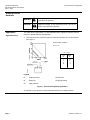
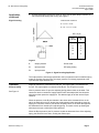
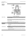
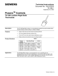
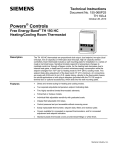
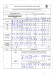
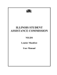
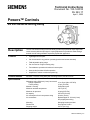
Technical Instructions
Document No. 155-124P25
RL 243-17
April 1, 2005
PowersTM Controls
RL 243 Reverse Acting Relay
Description
The RL 243 Reverse Acting Pneumatic Relay provides a proportional output signal that
varies inversely with the input signal. A spring adjustment is provided to allow setting a
desired reverse acting schedule required by a particular application.
Features
•
Lightweight and compact
•
Can be mounted in any position (mounting bracket and screws included)
•
Field adjustable spring range
•
Can be used as a signal inverting relay
•
Force-balance operation minimizes air consumption
•
lnternal relief provides fail-safe operation
•
Amplifies air volume to minimize system lag
Product Number
243-0024 Reverse Acting Relay with mounting bracket, and two screws.
Specifications
Operating range
Adjustment using 5/64-inch (2 mm) hex wrench
Range adjustment
Factory setting
Material - housing
Maximum ambient temperature
Maximum air pressure
Air capacity
Air consumption for air compressor sizing
Air connections
Mounting
Dimensions
Shipping weight
0 to 30 psi (0 to 207 kPa)
10 to 30 psi (69 to 207 kPa)
15 psi (103 kPa)
Glass-filled nylon
140°F (60°C)
30 psig (207 kPa)
230 scim (63 ml/s)
29 scim (8 ml/s)
Barbed nipple for 1/4-inch (6 mm)
OD polyethylene tubing
Mounting bracket provided
See Figures 5 and 6
0.27 lb (0.13 kg)
Siemens Industry, Inc.
Technical Instructions
Document Number 155-124P25
April 1, 2005
RL 243 Reverse Acting Relay
Warning/Caution
Notations
Application
Signal Reversing
WARNING
Personal injury/loss of life may occur if you do not perform
a procedure as specified.
CAUTION
Equipment damage, or loss of data may occur if you do not
perform a procedure as specified.
This relay has two applications. For both applications the supply air pressure must be
equal to or greater than the spring setting.
1. The relay reverses a controller signal to match the operation of a control element.
See Figure 1.
OPERATIONAL FORMULA:
B = SP – S1
SP = 15 psi
Input
S1
Output
B
0
5
10
15
15
10
5
0
Legend
B
Output pressure
S2 Not used
M
Supply air
SP Spring setting
S1
Input pressure
Figure 1. Reverse Acting Relay Application.
An increase in input pressure causes equivalent decrease in output pressure.
Page 2
Siemens Industry, Inc.
RL 243 Reverse Acting Relay
Application,
continued
Technical Instructions
Document Number 155-124P25
April 1, 2005
2. A typical application reverses the action of a face and by-pass damper actuator on a
coil used for both heating and cooling. See Figure 2.
OPERATIONAL FORMULA:
Signal Inverting
B = S1 if S1< 1/2 SP
B = SP – S1 if S1> 1/2 SP
SP = 15 psi
Input
S1 and M
Output
B
0
0
3
3
7.5
7.5
12
3
15
0
Legend
B
Output pressure
S2 Not used
M
Input pressure
SP Spring setting
S1
Input pressure
Figure 2. Signal lnverting Application.
The output pressure is directly proportional to the input pressure until one half the spring
setting is reached. After this point, the output pressure is inversely proportional to the
input until the output reaches zero.
Operation
Reverse Acting
See Figure 3
Supply air pressure is connected to the M port. The input signal is connected to the
S1 port. The output signal is connected to the B port. The S2 port is not used.
With no pressure at the S1 port, the adjusting spring pushes down on the stack. This
causes the stack to contact the supply-exhaust valve assembly which first closes the
exhaust port then opens the supply port. This allows supply air to flow into the B port
chamber.
When the pressure in the B port chamber is the same as the downward force on the
stack, the stack will move up, causing the supply-exhaust valve assembly to close the
supply port. Pressure at the S1 port causes an upward force on the stack that opposes
the downward force caused by the adjusting spring. The stack moves up allowing the
exhaust port to open, relieving the B port pressure.
When the B port pressure plus S1 pressure equals the downward force of the adjusting
spring, the stack will move down, closing the exhaust port.
Siemens Industry, Inc.
Page 3
Technical Instructions
Document Number 155-124P25
April 1, 2005
RL 243 Reverse Acting Relay
Operation,
Continued
See Figure 3
Figure 3. Relay Operation.
Signal lnverting
Connect the input signal to both M and S1 ports and connect the output signal to the B
port. Port S2 is not used.
With the spring set for 15 psi (103 kPa), the exhaust port is closed and the supply port is
open to the B chamber until S1 pressure plus B pressure equals 15 psi (103 kPa). As S1
increases, the exhaust port opens, causing B to decrease to maintain the S1 + B = 15 psi
(103 kPa) relationship.
A small leak port between M and B chambers assures fast response and prevents the
device from locking up on a loss of supply air pressure.
Mounting and
Installation
Surface Mounting
•
Do not locate the device in areas with excessive vibration or corrosive atmosphere.
•
This device may be branch mounted or surface mounted. Mount the relay vertically
or horizontally.
•
Install the relay so the port markings are visible and the spring adjustment screw is
accessible.
1. Attach the provided bracket to the mounting surface with two #8 or #10 sheet metal
screws (not provided).
2. Attach the relay to the bracket with the two 6-32 screws provided. The bracket has
tapped holes for this purpose.
Page 4
Siemens Industry, Inc.
RL 243 Reverse Acting Relay
Mounting and
Installation,
Continued
Technical Instructions
Document Number 155-124P25
April 1, 2005
3. Make all connections according to the piping diagram.
4. When disconnecting the tubing, use caution to avoid damaging the barbed nipples of
the relay.
The installation is now complete.
CAUTION:
Air supply must be clean, dry, and oil-free.
Adjustment
The relay has an adjustment spring that allows the output range to be increased or
decreased.
1. lnsert one gauge in the input line and another gauge in the output line. Use accurate
gauges when adjusting the relay.
2. lnsert a 5/64-inch (2 mm) hex Allen wrench to adjust the spring, as shown in
Figure 4.
3. Provide the desired maximum pressure to the input line.
4. Rotate the adjustment screw until the output pressure reads the lowest desired outlet
pressure.
Figure 4. Adjusting the Spring.
Reverse Acting
The spring can be adjusted to provide any range from 0 to 10 psi (0 to 69 kPa) to 0 to 30
psi (0 to 207 kPa). The air supply must be equal to or greater than the highest pressure
in the range.
Signal lnverting
The spring can be adjusted for 10 to 30 psi (69 to 207 kPa) resulting in a maximum
output pressure of 5 to 15 psi (34 to 103 kPa) respectively.
Adjust spring for twice the maximum output pressure desired. ln Figure 2, the spring is
set for 15 psi (103 kPa); therefore, the maximum output pressure is 7.5 psi (51 kPa).
Service
Siemens Industry, Inc.
Do not attempt to disassemble the relay. If the relay is inoperative, replace it.
Page 5
Technical Instructions
Document Number 155-124P25
April 1, 2005
RL 243 Reverse Acting Relay
Dimensions
Figure 5. Relay Dimensions.
Figure 6. Mounting Bracket Dimensions.
Information in this publication is based on current specifications. The company reserves the right to make changes in specifications and models as
design improvements are introduced. Powers is a registered trademark of Siemens Industry, Inc. Product or company names mentioned herein
may be the trademarks of their respective owners. © 2005 Siemens Industry, Inc.
Siemens Industry, Inc.
Building Technologies Division
1000 Deerfield Parkway
Buffalo Grove, IL 60089
+ 1 847-215-1000
Your feedback is important to us. If you have
comments about this document, please send them
to [email protected]
Document No. 155-124P25
Printed in the USA
Page 6