1
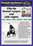
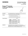
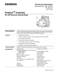
Technical Instructions
Document No. 155-055P25
SW 151-1
April 1, 2005
PowersTM Controls
SW 151 Positioning Switch
Description
The SW 151 Positioning Switch (standard type) is used to deliver any manually selected
pressure over a range of 15 psi. It has a wide variety of applications in pneumatic control
systems. The adjustment knob can be turned approximately 300 degrees.
The bleed type switch changes the outlet pressure 3 psi for 300 degree knob rotation.
The primary use is for manual reset of the RC-195 Receiver-Controller.
Several mounting arrangements can be used. Switches may be mounted on control
panels with descriptive name plates, surface-mounted on a wall or duct, or placed
directly on control center panels by omitting the dial faceplate. When the dial faceplate is
omitted, an inscription covering switch function is made directly on the panel itself. The
switch has a small body diameter which permits close center-to-center mounting. It can
be used with panels up to 3/8-inch thick.
Three standard dial plates are available. A blank plate is also available which can be
printed to order. A nomenclature plate is provided with space for indicating switch
operation.
The positioning switch has solid brass body parts for maximum resistance against
corrosion. In addition, a transparent face cover protects both the dial and nomenclature
plates.
Table 1.
Product Numbers
Switches
Mounting Kits
Dial Plates
Product
Number
Description
Part
Number
Description
Part
Number
151-142
Standard Switch
151-146
151-097
151-143
Bleed Switch
Panel Mounting
(Table 2)
151-147
Surface
Mounting
(Table 3)
151-148
Graphic Panel
(Table 4)
Description
Nomenclature Plates
Part
Number
Description
Blank **
151-098
Blank **
151-118
Warmer *
151-151
Humidity
151-119
151-150
Close *
Increase *
151-152
786-102
Static Pressure
Damper Control
786-103
Valve Control
786-104
Thermostatic Control
NOTE: For a complete installation, order: a switch, mounting kit, dial plate and nomenclature plate.
* Reversible plate: Clockwise on one side, counterclockwise on other side.
** See Field Purchasing Guide for “print to order” information.
Siemens Building Technologies, Inc.
Technical Instructions
Document Number 155-055P25
April 1, 2005
Specifications
SW 151 Positioning Switch
Output:
Standard
Operating
Bleed
Capacity
Medium Air
Ambient Temperature
Physical
Maximum Air Pressure
Air Consumption
(151-143)
(151-142)
Dimensions
Shipping Weight
Air Connections
Color (knob and dial plate)
*Body tapping is 1/16 NPT
0 to 15 psi (0 to 103 kPa)
for 300° knob rotation
7 1/2 to 10 1/2 psi (52 to 72 kPa)
for 300° knob rotation
625 SCIM (171 ml/s)
Maximum 160°F (71°C)
Minimum -20°F (-29°C)
30 psig (207 kPa)
35 SCIM (9.5 ml/s)
None
See Figures 7 and 8
2 lb (0.9 kg)
1/4-inch OD plastic tubing*
Gray
Application
Positioning switches have many applications in pneumatic systems. They may be used to
control air-operated equipment directly, such as damper motors or valves, or they may be
used to manually control a complete heating system. Positioning switches are also used
in numerous special applications.
Operation
An adjusting knob varies positioning switch control pressure. Turning the adjusting knob
approximately 300° will gradually change the control pressure from 0 to 15 psi (maximum
supply pressure). When the knob indicator is pointed up, the switch passes
approximately 7-1/2 psi when using 15 psi supply. Assume a control pressure of 10 psi is
needed from positioning switch. By turning the adjusting knob clockwise, increased
spring pressure on the exhaust valve body seats the exhaust valve ball. Further rotation
of the knob forces the push pin to unseat the supply valve ball. As air accumulates in the
exhaust valve chamber, it exerts pressure on the diaphragm in opposition to that of the
adjusting spring. The knob is turned until the branch pressure reads 10 lbs. At this
position there is sufficient pressure in the exhaust valve chamber to seat the supply valve
ball. Airflow then stops. If control pressure drops, the supply valve again opens to
maintain constant pressure. When the adjusting knob is turned counterclockwise, the
adjusting spring pressure is reduced. While the supply valve remains closed, the exhaust
valve opens until the control air pressure reaches its new setting.
Standard Type
(See Figure 1)
Figure 1. Standard Type.
Page 2
Siemens Industry, Inc.
SW 151 Positioning Switch
Bleed Type
(See Figure 2)
Technical Instructions
Document Number 155-055P25
April 1, 2005
An adjusting knob varies positioning switch control pressure. Turning the adjusting knob
approximately 300° will gradually change the control pressure from 7-1/2 to 10-1/2 psi
(max. supply pressure). When the knob indicator is pointing up, the switch passes
approximately 9 psi when using a restricted supply. Assume a control pressure of 10 psi
is needed from positioning switch. By turning the adjusting knob clockwise, increased
pressure on the exhaust valve body seats the exhaust valve ball. As air accumulates in
the exhaust valve chamber, it exerts pressure on the diaphragm in opposition to that of
the adjusting spring. Any excess pressure above 10 psi would bleed off through the
exhaust valve, and the air pressure would remain constant at 10 psi.
Figure 2. Bleed Type.
Installation
Flush Mounting on Wall
Siemens Industry, Inc.
NOTE:
See Document No. 155-252P25 (TB-238) for recommendations for mounting
these switches in electrical wall boxes or on walls with masonry or drywaII
construction.
Page 3
Technical Instructions
Document Number 155-055P25
April 1, 2005
SW 151 Positioning Switch
Panel Mounting
Table 2. Panel Mounting Kit Number 151-146
(See Figure 3).
Item
Description
Qty
Material
1
No. 2-56 × 1/4 Round Head Screw
1
Brass
2
Washer
1
Brass
3
No. 6-32 Hex Nut
2
Brass
4
Lock Washer
2
Cad. Pl.
5
No. 6-32 × 5/16 Flat Head Screw
2
Brass
6
No. 3-48 × 1/8 Bind. Head Screw
2
Brass-Cad Pl.
7
Mounting Plate
1
Steel
8
Dial Faceplate
1
Polystyrene
9
No. 6-32 × 1/2 Flat Head Screw
2
Brass
Figure 3. Panel Mounting (See Table 2).
1. Remove switch from box, being careful not to turn adjusting screw. The switch is
shipped factory-set to be closed; that is, to pass no air. Remove knob from adjusting
screw shaft.
2. Screw stop screw (1) to mounting plate (7). Stop screw hole is closest to adjusting
screw. Make certain small stop screw washer (2) is in correct position. Fasten plate
(7) to switch with two regular flat head screws (5). Make sure stop screw (1) fits into
recess of switch body.
3. Connect 1/4-inch OD plastic tubing to fittings on switch body. Note “R”and “S” port
markings. Connect other ends of connecting tubes to supply and return lines through
hole in panel.
4. With stop screw (1) below adjusting screw shaft, attach mounting plate (7) to panel
with two flat head screws (9).
5. Place desired dial and nomenclature plates in recesses in the dial faceplate (8). Then
affix to mounting plate (7) with two binding head screws (6).
6. Tighten knob to shaft. Turn knob fully counterclockwise. Switch should pass 0 psi
with 15 psi air supply.
The installation is now complete.
Page 4
Siemens Industry, Inc.
SW 151 Positioning Switch
Panel Mounting,
Continued
Technical Instructions
Document Number 155-055P25
April 1, 2005
Figure 4 shows the minimum distances from center to center of switches in order to
mount the maximum number of switches on a panel.
Figure 4. Panel Spacing.
Siemens Industry, Inc.
Page 5
Technical Instructions
Document Number 155-055P25
April 1, 2005
Surface Mounting
SW 151 Positioning Switch
1. Remove knob from switch.
2. Screw mounting bracket (10) to surface.
3. Screw stop screw (1) to mounting plate (7). Stop screw hole is closest to adjusting
screw. Make certain small washer (2) is in place. Fasten plate (7) to switch body using
two short flat head screws (5). Stop screw head fits recess in switch body.
4. With stop screw below adjusting screw shaft, screw mounting plate (7) to mounting
bracket (10) using the two 100° flat head screws (9), hex nuts (3), and lock
washers (4).
5. Place dial and nomenclature plates in recess of dial faceplate (8).
6. Tighten knob to shaft. Turn knob fully counterclockwise. Switch should pass 0 psi with
15 psi air supply.
The installation is now complete.
Figure 5. Surface Mounting (See Table 3).
Table 3. Surface Mounting Kit No. 151-147 (See Figure 5).
Item
Page 6
Description
Oty.
Material
1
No. 2-56 × 1/4 Rd Head Screw
1
Brass
2
Washer
1
Brass
3
No. 6-32 Hex Nut
2
Brass
4
Lock Washer
2
Cad. Pl.
5
No. 6-32 × 5/16 Flat Head Screw
2
Brass
6
No. 3-48 × 1/8 Bind. Head Screw
2
Brass
Cad Pl.
7
Mounting Plate
1
Steel
8
Dial Faceplate
1
Polystyrene
9
No. 6-32 × 1/2 Flat Head Screw
2
Brass
10
Mounting Bracket
1
Steel
Siemens Industry, Inc.
SW 151 Positioning Switch
Graph-O-Matic Panel
Mounting
Technical Instructions
Document Number 155-055P25
April 1, 2005
1. Remove switch from box, being careful not to turn adjusting screw. The switch is
factory-set to be closed; that is, to pass no air. Remove knob from adjusting screw
shaft.
2. Drill hole in panel using a No. 55 drill. Secure mounting plate (3) to panel with drive
screw (6).
3. Screw stop screw (1) into round mounting plate (3). Make certain small stop screw
washer (2) is in correct position. (See Figure 3).
4. Noting “R” and “S” port markings, connect 1/4-inch OD plastic tubing to switch. Join
other ends of connecting tubing to supply and return line.
5. Push switch through hole and screw mounting plate (3) to switch body. Note
clearance hole for stop screw (1) head. Tighten clamping nut (5) after positioning
stop screw so it is directly beneath adjusting screw shaft.
6. Tighten knob to shaft. Turn knob fully counterclockwise. Switch should pass 0 psi
with 15 psi air supply.
7. When switches are grouped together, provide a minimum center to center distance
as shown in Figure 4.
The installation is now complete.
Figure 6. Graph-O-Matic Panel Mounting (See Table 4).
Table 4. Graphic Panel Mounting Kit No. 151-148 (See Figure 6).
Item
1
2
3
4
5
6
Siemens Industry, Inc.
Description
No. 2-56 × 3/16 Fat Head Screw
Washer
Round Mounting Plate
No. 6-32 × 5/16 Fat Head Screw
Clamping Nut
No. 11 × 1/8 Drive Screw
Qty
2
2
1
2
1
1
Material
Brass
Brass
Steel
Brass
Brass
Steel
Page 7
Technical Instructions
Document Number 155-055P25
April 1, 2005
SW 151 Positioning Switch
Dimensions
* For panels more than 0.106 inches (2.7 mm) thick. For thinner panels, drill 0.210-inch (5.3 mm) hole
(No. 4 drill bit) and use two hex nuts (3) to secure the mounting plate (7) to panel.
Figure 7. Panel Mounting Dimensions.
Figure 8. Switch Dimensions.
Page 8
Siemens Industry, Inc.
SW 151 Positioning Switch
Technical Instructions
Document Number 155-055P25
April 1, 2005
Construction
Figure 9. Construction.
Table 5. Product Numbers 151-142 and 151-143.
Item Part No.
1
2
3
Description
Drag Pin
151-113 Adjusting Knob
Adjusting Screw
Item Part No.
Description
Qty.
Material
1
Nylon
13
1
Plastic
14
Switch Body
1
Cad. Pl. Stl.
15
151-141 Filter (1 only-Bleed Sw.)
Qty. Material
2
Phos. Brnz.
1
Brass
Ball Valve
2
Stn. Steel
Exhaust Valve Body
1
Brass
4
Spring Thrust Flange
1
Brass
16
5
Spring Housing
1
Brass
17
Diaphragm
1
Neoprene
6
Diaphragm Nut
1
Brass
18
No. 6-32 × 3/8 Screw
6
Brass
7
Diaphragm Ring
1
Brass
19
Spring (Standard)
1
Music Wire
Spring (Bleed)
1
Music Wire
8
Diaphragm Plate
2
Brass
19
9
Push Pin
1
Stl. Steel
20
No. 8-32 × 1/8 Set Screw
1
Steel
10
Stool
1
Brass
21
Spring
2
Stl. Steel
11
Spring
1
Music Wire
22
043-345 Plug (Bleed only)
1
Steel
Brass
23
141-207 Fitting (Bleed only Qty. 1)
2
Brass
12
Spring Adjusting Screw
1
Information in this publication is based on current specifications. The company reserves the right to make changes in specifications and models as
design improvements are introduced. Powers is a registered trademark of Siemens Industry, Inc. Product or company names mentioned herein
may be the trademarks of their respective owners. © 2005 Siemens Industry, Inc.
Siemens Industry, Inc.
Building Technologies Division
1000 Deerfield Parkway
Buffalo Grove, IL 60089
+ 1 847-215-1000
Your feedback is important to us. If you have
comments about this document, please send them
to [email protected]
Document No. 155-055P25
Printed in the USA
Page 9