1
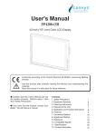
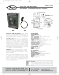
Technical Instructions
Document No. 155-070P25
TH 356-1
September 24, 2004
PowersTM Controls
TH 356 Limitem Rigid Bulb
Thermostat
Description
The TH 356 Rigid Bulb Limitem is a pneumatically operated thermostat available either
as direct acting or reverse acting in a variety of ranges.
Features
•
Copper motor tube and invar steel rod sensing element
•
Two-valve design eliminates wasting of air
•
18-inch (457 mm) bulb useful where stratification occurs
•
Flange, locknut and screws for duct mounting included
Table 1.
Product Numbers
Application
Product
Number
Operating Range
Action
356-0750
30 to 180°F (-1 to 82°C)
356-0012
0 to 100°F (-18 to 38°C)
Direct
Acting
356-1005
30 to 180°F (-1 to 82°C)
356-1006
100 to 250°F (38 to 121°C)
356-0013
0 to 100°F (-18 to 38°C)
Reverse
Acting
The 356 Rigid Bulb Limitem is recommended for use in controlling duct air
temperatures such as mixed air or discharge air. It can also be used as a high or low
temperature limit control. In unit ventilator applications it is used as a low limit control.
When used with a well, it can be used for water temperature control.
Siemens Industry, Inc.
Technical Instructions
Document No. 155-070P25
September 24, 2004
Specifications
Accessories
Operating range
Normal air supply pressure
Maximum supply air pressure
Maximum external pressure on bulb
Maximum ambient temperature
case
bulb
30 to 180°F
100 to 250°F
40 to 120°C
0 to 100°F
-20 to 40°C
Factory sensitivity setting
Sensitivity range adjustable
Temperature response
Mounting
Air connection
Shipping weight
Dimensions
Bulb length
Case
Flange O.D.
Gauge tees (pkg of 5)
Pipe plug
Well (copper)
Swivel flange mounting kit
Flange mounting screw (3 required)
Replacement gauges
0 to 30 psi (bottom)
0 to 30 psi/0 to 200 kPa (back)
Figure 1. Direct Acting Operation.
Page 2
See Table 1
18 or 25 psi (124 or 172 kPa)
30 psi (207 kPa)
250 psi (1,722 kPa)
200°F (93°C)
225°F (107°C)
250°F (121°C)
250°F (121°C)
250°F (121°C)
250°F (121°C)
1-1/4 psi/F (15 kPa/C)
1/4 to 2 psi/F (3 to 25 kPa/C)
1/2°F (0.9°C)
Flange or 3/8-inch NPT
1/8-inch NPT
2 lbs (0.9 kg)
18 inches (457 mm)
3 in. L × 1-1/2 in. diameter
(76 mm × 38 mm)
2-9/16 in. (65 mm)
141-436
403-007
358-051
356-090
034-256J
P142-308
P142-373
Figure 2. Reverse Acting Operation.
Siemens Industry, Inc.
TH 356 Limitem Rigid Bulb Thermostat
Technical Instructions
Document No. 155-070P25
September 24, 2004
Operation
The copper motor tube and invar steel rod average temperature changes by measuring
the difference in expansion between the two metals. This positions the two-valve
mechanism in response to the slightest temperature changes.
Direct Acting
As temperature increases, the motor tube expands and moves the supply valve away
from the ball valve, causing a gradual increase of air pressure in the return line. (The ball
valve is closed against the exhaust valve while the supply valve is open, preventing
constant air waste.) Increased pressure in the return air chamber causes the exhaust
valve diaphragm to compress the sensitivity spring. The exhaust valve is moved away
from the ball valve, closing against the supply valve. This throttles the supply air in
proportion to the temperature change established by the sensitivity spring.
As the temperature drops, the motor tube contracts. This moves the ball valve away from
the exhaust valve and gradually reduces the return line air through the exhaust port.
Lower pressures in the return air chamber force against the exhaust valve. The
sensitivity spring expands and the exhaust valve moves gradually to the ball valve
reducing the return air waste.
Reverse Acting
As temperature increases, the motor tube expands and moves the supply valve and the
ball valve away from the exhaust valve, causing a gradual decrease of air pressure in the
return line.
(The ball valve is closed against the supply valve while the exhaust valve is open,
preventing air waste.) Decreased pressure in the return air chamber causes the exhaust
valve diaphragm to allow the sensitivity spring to expand. The exhaust valve is moved
toward the ball valve, closing both the exhaust and the supply valves against the ball.
This throttles the supply air in an inverse proportion to the temperature change
established by the sensitivity spring.
As the temperature drops the motor tube contracts, moving the ball valve away from the
supply valve, gradually increasing the return line air supply valve port. Higher pressures
in the return air chamber increase force against the exhaust valve diaphragm. The
sensitivity spring compresses and the ball valve moves gradually to the supply valve
reducing the supply air volume to the return air chamber.
The throttling range is changed by sliding the sensitivity spring. Sensitivity is most
gradual 0.25 psi/1°F or 3.1 kPa/°C when the spring's open end is under the adjusting
screw. Throttling is most positive 2psi/1°F or 24.8 kPa/°C when the solid end of the
spring is under the adjusting screw. Factory setting is at the center of the sensitivity
spring, or 1-1/4 psi/1°F or 15.5 kPa/°C. Any change to the spring’s position offsets
control and makes resetting of the dial necessary.
3
Return line vent, factory set for 5 to 7 CIM (1.37 to 1.91cm /s), prevents the air being
trapped in the line when the Limitem is piloted from a room thermostat.
Siemens Industry, Inc.
Page 3
Technical Instructions
Document No. 155-070P25
September 24, 2004
Installation
NOTE:
Duct Mounting
(See Figure 3)
Flange, lock nut and sheet metal screws are provided for duct mounting.
Calibrate the Limitem for your application after installation.
1. Remove the flange from the Limitem and use the flange as a template. Mark the
location of the center hole and three screw holes. Drill the holes.
2. Slip the flange over the rigid bulb and secure with the lock nut.
3. Fasten the Limitem to the duct with the sheet metal screws provided.
4. Attach air gauges and tees in the supply and return lines.
The installation is now complete.
Figure 3. TH 356 Rigid Bulb Limitem.
Alternate Duct Mounting
The swivel flange mounting kit Part No. 356-090 is available for mounting the Limitem in
Swivel Flange Mounting. ducts as small as 13 inches (330 mm) wide.
(See Figure 4)
1. Use the swivel flange as a template to mark the location of the center hole and three
screw holes.
2. Drill the holes and attach the flange.
3. Remove the standard mounting flange from the Limitem.
4. Carefully thread the Limitem through the 3/8-inch NPT tapped swivel socket.
5. Fasten the flange to the duct with the sheet metal screws provided.
The installation is now complete.
Page 4
Siemens Industry, Inc.
TH 356 Limitem Rigid Bulb Thermostat
Technical Instructions
Document No. 155-070P25
September 24, 2004
Installation,
continued
Figure 4. Swivel Flange Mounting Kit part No. 356-090.
Well Mounting
(See Figure 5)
1. Exercise care when installing the limitem into a well.
2. The Limitem must fit freely in the well to operate properly.
3. Screw the limitem into the well finger tight.
4. Tighten the set screw on the well to hold the limitem securely.
The installation is now complete.
Figure 5. Limitem Well Mounting Kit Part No. 358-051.
Calibration
1. Remove the cover.
To Change Setpoint
2. Turn the dial adjustment screw with a screwdriver (Figure 6) to change to the desired
setpoint.
Figure 6. Limitem Cover Removed.
Siemens Industry, Inc.
Figure 7. Using the Pressure Test Port.
Page 5
Technical Instructions
Document No. 155-070P25
September 24, 2004
Calibration,
continued
To calibrate
1. Using a test thermometer, accurately measure the temperature at the bulb.
2. Set the dial to the bulb temperature by turning the dial adjustment screw with a
screwdriver.
NOTE:
You must use a screwdriver. Do not attempt to change the dial by rotating it with
your hand.
3. If permanent return air gauge is not installed, use the pressure test port. See Figure 6
for its location.
4. Loosen the test port screw about 1/2 turn, and slip a 3/16-inch I.D. rubber hose
connected to the test gauge over the pressure test port. See Figure 7.
5. If the return pressure does not read 7 to 8 psi (48-55 kPa), turn the dial adjustment
screw with a screwdriver until pressure is 7 to 8 psi (48-55 kPa).
6. Loosen the dial screws and turn dial until the temperature at the bulb and dial is
identical. Tighten the screws.
The thermostat is now calibrated and setpoint may be changed as desired.
Sensitivity Adjustment The sensitivity adjustment is factory set with the sensitivity spring tab in position 6 of the
spring retainer. This is approximately mid span of the sensitivity. Move the sensitivity spring
to a lower slot number for more gradual setting. Move the sensitivity spring to a higher slot
number for more positive setting. See Table 2.
To change the sensitivity:
1. Loosen the dial screws. (See Figure 6)
2. Loosen the dial adjustment screw.
3. Lightly press, but do not bend the spring retainer. (See Figure 8.)
4. Move the sensitivity spring to the new position. See Figure 8. Table 2 gives the
sensitivity spring tab location and the corresponding sensitivity value.
NOTE:
The tab may be installed in either side of the spring retainer.
5. Make sure that the dial adjustment screw point touches the sensitivity spring.
6. Recalibrate the unit.
7. If you need to adjust again, allow five minutes for the control cycle to settle before
repeating the steps above.
Page 6
Siemens Industry, Inc.
TH 356 Limitem Rigid Bulb Thermostat
Technical Instructions
Document No. 155-070P25
September 24, 2004
Sensitivity
Adjustment,
continued
Table 1.
Slot
No.
Sensitivity
Psi/°F
1
2
3
4
5
6
7
8
9
10
11
0.29
0.44
0.64
0.89
1.03
1.22
1.41
1.61
1.80
2.0
2.0
Figure 8. Sensitivity Spring Setting.
Troubleshooting
If the limitem fails to operate properly, use Table 3 as a troubleshooting guide. Make
certain the thermostat receives 18 to 30 psi (124 to 207 kPa) of clean, dry, oil-free supply
air. Also, use a test gauge with a length of 3/16" I.D. rubber hose to measure the return
pressure at the test port if permanent gauges are not available.
Service
The limitem cannot be serviced. Replace the thermostat if inoperative after checking the
troubleshooting table.
Table 3. Troubleshooting Chart.
Complaint
Check
Probable Cause
Corrective Action
Return Line pressure
stays at approximately
zero
Supply air Pressure
Low Pressure
As Required
If return is still
zero psi
Defective valve
assembly
Replace thermostat
If return
pressure
increases
Out of calibration
or damaged
sensing element
If return
pressure
remains high
Defective valve
assembly
If return
pressure drops
to zero
Out of calibration
Recalibrate
Return Line pressure
stays at approx.
supply pressure
Depress exhaust
valve
Using a
screwdriver,
rotate setpoint
dial counterclockwise to the limit
stop
1. Recalibrate
2. With 6 to 9 psi return pressure, vary
temperature at the bulb. If no change in
return pressure, replace thermostat.
Replace thermostat
Excessive air leakage
from exhaust valve
Supply and return line connection
Connections are
interchanged
Reverse the supply and return connections
Temperature cycles
rapidly
Sensitivity setting
Improper setting
Move the sensitivity spring to a more gradual
(lower #) slot setting. See Sensitivy
Adjustment.
Temperature wanders
from control point
Sensitivity setting
Improper setting
Move the sensitivity spring to a more positive
(higher #) slot setting. See Sensitivity
Adjustment.
Siemens Industry, Inc.
Page 7
Technical Instructions
Document No. 155-070P25
September 24, 2004
Figure 9. Construction of the Rigid Bulb Limitem.
Table 4. Parts List.
Table 4. Parts List, continued.
Item
Part
Qty.
Part Number
Item
Part
Qty
Part Number
1
2
3
1
1
1
–
—
1
—
2
—
4
—
19
20
21
22
23
24
25
Body
Lower Spacer
Retaining Ring
Spring
Ball Valve
Sealing Gasket
Supply Valve Body
1
2
1
1
1
2
1
–
–
–
–
–
–
–
1
—
26
27
28
29
30
31
32
Diaphragm Ring
Retaining Spring
Sensitivity Spring
Dial Adjustment Screw
Dial Screws
Bleed Screw
#6-32 × 1-7/8” Lg.Fil. hd.
machine screw
Test Plug
Test Valve Body
Valve Gasket
Pointer
1
1
1
1
2
1
2
–
–
–
–
–
–
–
14
15
16
17
Cover
Dial
Lock Plate
Bridge
Upper Spacer
#6-32 × 1-3/8" Lg.Fil. Hd.
screw
Housing Ring
Supply Valve
Supply Valve Diaphragm
#3-48 × 7/8" Lg.Fil. Head
Screw
110. Ring
Duct Flange
Washer
Locknut
Flange
Motor Tube Assembly
"0" Ring
1
1
1
1
833-009
–
–
–
18
Screen Filter
4
5
6
7
8
9
10
11
12
13
1
—
1
—
2
—
1
—
1
1
1
1
1
–
–
–
–
–
–
2
–
1
33
34
35
36
Information in this publication is based on current specifications. The company reserves the right to make changes in specifications and models as
design improvements are introduced. Product or company names mentioned herein may be the trademarks of their respective owners.
© 2004 Siemens Industry, Inc.
Siemens Industry, Inc.
Building Technologies Division
1000 Deerfield Parkway
Buffalo Grove, IL 60089
+ 1 847-215-1000
Your feedback is important to us. If you have
comments about this document, please send them
to [email protected]
Document No. 155-070P25
Printed in the USA
Page 8