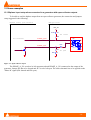
1
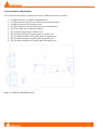
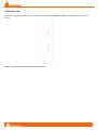
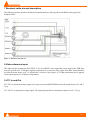
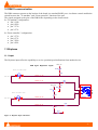
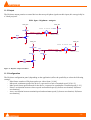
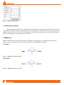
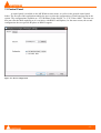
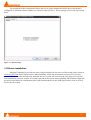
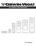
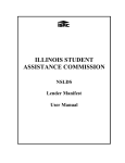
USB Sync Board
User Manual
Version : 1.01 (April 2009)
© 2009 Merging Technologies
Merging Technologies
Le Verney, CH-1070 Puidoux Switzerland
Tel: +41 21 946 04 44 ● Fax: +41 21 946 04 45
www.merging.com
Please read the following information very carefully before attempting any installation. Failure to comply with
the precise instructions may result in damage to your Merging hardware. Please read this entire section of the
manual carefully before.
1 Important notice
1.1 STATIC DANGER NOTICE:
Please note that the USBSync board contains delicate electronic components that can be damaged or even
destroyed when exposed to static electricity. Take all necessary precautions not to discharge static electricity
when touching any of the USBSync components.
1.2 INFORMATION FOR THE USER:
USBSync and its daughter card comply with the following specifications:
EMC Emissions
EN 55022: 1994 /A1: 1995 /A2: 1997 Class A ITE emissions requirements (EU)
FCC 47 CFR Part 15 Class A emissions requirements (USA)
EMC Immunity
EN 50082-1: 1992 EMC residential, commercial and light industrial generic immunity standard.
FCC Notice
This product has been tested and found to comply with the limits for a Class A digital device, pursuant to Part
15 of the FCC rules. Operation is subject to the following two conditions: (1) This device may not cause
harmful interference, and (2) This device must accept any interference received, including interference that may
cause undesired operation.
These limits are designed for providing reasonable protection against harmful interference in a residential
installation. This equipment generates, uses and can radiates radio frequency energy and, if not installed and
used in accordance with the instructions contained in this manual, may cause harmful interference to radio and
television communications. However, there is no guarantee that interference will not occur in a particular
installation.
NOTE: Connecting this device to peripheral devices that do not comply with CLASS A requirements or using
an unshielded peripheral data cable could also result in harmful interference to radio or television reception.
The user is cautioned that any changes or modifications not expressly approved by the party responsible for
compliance could void the user’s authority to operate this equipment. To ensure that the use of this product
does not contribute to interference, it is necessary to use shielded I/O cables.
CE Notice
Such a marking is indicative that this system’s devices meet the following applicable technical standards:
•
EN 55022 – “Information Technology Equipment - Radio disturbance characteristics Limits and
methods of measurement”
•
EN 50082-1: 1992 – “Electromagnetic compatibility – Generic immunity standard Part 1: Residential,
commercial, and light industry”
This product is classified for use in a typical Class A commercial environment, and is not designed or intended
for use in other EMC environments. The user of this product is obliged for proper use and installation of the
product and for taking all steps necessary to remove sources of interference to telecommunications or other
devices.
-2-
2 USBSync Board warranty information
This product is warranted to be free of defects in materials and workmanship for a period of one year from the
date of purchase. Merging Technologies, Inc. extends this Limited Warranty to the original purchaser.
In the event of a defect or failure to confirm to this Limited warranty, Merging Technologies, Inc. will repair or
replace the product without charge within sixty (60) days. In order to make a claim under this limited warranty,
the purchaser must notify Merging Technologies, Inc. or their representative in writing, of the product failure.
In this limited warranty the customer must upon Merging Technologies, Inc. request, return the product to the
place of purchase, or other local designation, for the necessary repairs to be performed. If the consumer is not
satisfied with the repair, Merging Technologies, Inc. will have the option to either attempt a further repair, or
refund the purchase price.
This warranty does not cover: (1) Products which have been subject to misuse, abuse, accident, physical
damage, neglect, exposure to fire, water or excessive changes in the climate or temperature, or operation
outside maximum rating. (2) Products on which warranty stickers or product serial numbers have been removed
altered or rendered illegible. (3) The cost of installations, removal or reinstallation. (4) Damages caused to any
other products.
-3-
3 Table of contents
1 Important notice .................................................................................................................................................. 2
1.1 STATIC DANGER NOTICE: ..................................................................................................................... 2
1.2 INFORMATION FOR THE USER: ............................................................................................................ 2
2 USBSync Board warranty information ............................................................................................................... 3
3 Table of contents ................................................................................................................................................. 4
4 Introduction ......................................................................................................................................................... 5
5 USBSync Board features overview..................................................................................................................... 5
6 USBSync board specifications ............................................................................................................................ 5
6.1 Block diagram .............................................................................................................................................. 5
6.2 Connectors and jumpers ............................................................................................................................... 6
6.3 Bracket view................................................................................................................................................. 7
7 Breakout cable pin-out description...................................................................................................................... 8
8 Video reference input .......................................................................................................................................... 8
9 LTC In and Out ................................................................................................................................................... 8
10 RS422 communication ...................................................................................................................................... 9
11 Bi-phase............................................................................................................................................................. 9
11.1 Input ........................................................................................................................................................... 9
11.2 Output....................................................................................................................................................... 10
11.3 Configuration ........................................................................................................................................... 10
11.4 Watchdog capability................................................................................................................................. 11
12 MIDI port ........................................................................................................................................................ 11
12.1 Input ......................................................................................................................................................... 11
12.2 Ouput ........................................................................................................................................................ 11
13 Control Panel................................................................................................................................................... 12
14 Drivers installation .......................................................................................................................................... 13
15 Some examples................................................................................................................................................ 14
15.1 Biphase input setup when connected to a generator with open-collector outputs ................................... 14
16 Contacting Merging Technologies .................................................................................................................. 15
-4-
4 Introduction
This document presents and describes the Merging Technologies USB based synchronization solution. This is a
PCI form factor board that is intended to be plugged into a PCI slot.
5 USBSync Board features overview
The Merging Technologies USBSync board is designed to bring synchronization capabilities to PC software
through a USB connection.
Here is a quick summary of features:
• USB v2.0 Full speed compliant
• Video reference input
• LTC input and output
• RS422 connection (machine and controller)
• MIDI connection
• Bi-phase input and output
6 USBSync board specifications
6.1 Block diagram
Figure 1 - Block diagram of USB Sync board
-5-
6.2 Connectors and jumpers
The connectors and jumpers implemented on the USBSync board are as follow:
•
•
•
•
•
•
•
•
•
•
J2: DB9 connector, for RS422 communication
J3: USB connector type B, not soldered on production boards
J4: DB15 connector, for breakout cable
J5: USB connector, for internal connection to motherboard
JP2: Erase flash, do not short this jumper
JP5: Atmel microprocessor manual reset
JP6: 56 Ohm pull-up on bi-phase phase A positive pin
JP7: 56 Ohm pull-down on bi-phase phase A negative pin
JP8: 56 Ohm pull-up on bi-phase phase B positive pin
JP9: 56 Ohm pull-down on bi-phase phase B negative pin
Figure 2 - Connectors and jumpers layout
-6-
6.3 Bracket view
The following picture shows a view of the PCI bracket with the DB9 and DB15 connectors to the external
world.
Figure 3 - USB Sync board bracket with the two connectors
-7-
7 Breakout cable pin-out description
The following picture describes the physical implementation of the signals on the DB15 male plug of the
breakout cable.
Figure 4 - Breakout cable pin-out
8 Video reference input
This input accepts a composite PAL/NTSC or Tri-level HDTV video signal that can be used by the USB Sync
board to generate LTC or Bi-phase signals synchronous to a reference video signal. This BNC input should be
used for the main “house sync” or “black-burst” reference video signal. A 75 Ohm termination can be applied
on the input signal via a software configuration.
9 LTC In and Out
LTC IN is a symmetrical input signal. It accepts an external SMPTE/EBU timecode signal between 0.2 and 5
Vp-p.
LTC OUT is a symmetrical output signal. The signal generated has a maximum output level of 3.3 Vp-p.
-8-
10 RS422 communication
The DB9 connector present on the bracket of the board is a standard RS422 port. A software control enables the
switch between the “To machine” and “From controller” function of the port.
The signals assigned to the pins of the DB9 differ depending on the chosen mode.
In “To machine” configuration:
• Pin 3: RX+
• pin 8: RX+
• pin 7: TX+
• pin 2: TXIn “From controller” configuration:
• pin 3: TX+
• pin 8: TX• pin 7: RX+
• pin 2: RX-
11 Bi-phase
11.1 Input
The Bi-phase input offers the capability to receive position/speed indications from another device.
VCC_5V
USB Sync Biphase input
R108
Phase A female DIN
56
JP6
3
1
5
4
White wire
2
Red wire
PHASE_A_IN+
R64
PHASE_A_IN-
220
VCC_5V
JP7
R30
R17
U8
1
8
2
3
7
4
6
56
56
Phase B female DIN
5
JP8
1
5
4
2
Red wire
3
PHASE_B_IN+
PS8802-2
White wire
R82
PHASE_B_IN-
220
JP9
R19
56
Figure 5 - Bi-phase input schematics
-9-
11.2 Output
The Bi-phase output permits to control devices that accept bi-phase signals on their input, this can typically be
a 35mm projector.
USB Sync Biphase output
VCC_5V
VCC_5V
Phase A female DIN
R31
220
R32 220
3
3
1
5
4
2
PHASE_A_OUTRed wire
White wire
R35
1
Q3
2
10k
VCC_5V
VCC_5V
Phase B female DIN
R23
220
C17
PHASE_B_OUTRed wire
0
R25
R26
1
5
4
220
White wire
NC
3
0
3
2
R77
R83
Q5
2
1
10k
Figure 6 - Bi-phase output schematics
11.3 Configuration
The Bi-phase configuration panel (depending on the application) offers the possibility to select the following
settings:
- Pulse/frame: number of Bi-phase pulses per video frame [1-100]
- Min speed: minimum speed of the device, expressed in a ratio of nominal speed [1/30-1/2]
- Max speed: fastest speed allowed for the device, expressed as a multiplier of nominal speed [1-30]
- PAccn: acceleration between slowest speed and nominal speed [1(slowest acceleration)-20(fastest
acceleration)]
- Accn: acceleration between nominal speed and maximum speed [1(slowest acceleration)-20(fastest
acceleration)]
- 10 -
Figure 7 - Bi-phase configuration
11.4 Watchdog capability
Watchdog functionality has been implemented on the Bi-phase output of the board. This means that it is
ensured that the Bi-phase stream stops properly (with an appropriate deceleration) if the software or operation
system crashes or freezes. This is a kind of emergency stop that ensures that the device driven by the Bi-phase
pulses is not damaged if something runs out of control.
12 MIDI port
MIDI communication between the USB Sync board and an external device is available through two DIN
female connectors. The pin-out of the connectors matches standard MIDI connections.
12.1 Input
Figure 8 - MIDI input connector pin-out
12.2 Ouput
Figure 9 - MIDI output connector pin-out
- 11 -
13 Control Panel
A control panel is available in the MS Windows start menu, as well as in the general control panel
folder. The first tab of this application enables the user to select the configuration of each board present in the
system. The configurations available are “LTC/Bi-Phase/Video+RS422” or “LTC/Video+Midi”. The first one
does not offer the Midi capability as it is exclusive with RS422 and Biphase, for the same reason, the second
configuration does not provide Bi-phase or RS422 support.
Figure 10 - Device configuration
- 12 -
The second tab of the control panel allows the user to select whether the RS422 port of the board is
configured as “Machine control”(Master) or “Remote control”(Slave). These settings are saved in a per board
basis.
Figure 11 - RS422 settings
14 Drivers installation
Merging Technologies provides the users with an installer for the drivers of the board; please check at
www.merging.com for the latest version. When installing, follow the instructions on screen. If a previous
version of the drivers has already been installed, the new version will overwrite the files, there is no need to
first uninstall the previous version. If a board is present in the system when installing, MS Windows might ask
the user several times for confirmation, this is the normal behavior as the USB Sync board is seen as several
devices by the system.
- 13 -
15 Some examples
15.1 Biphase input setup when connected to a generator with open-collector outputs
To be able to read the biphase output from an open-collector generator, the connection and jumpers
setup suggested is the following:
Biphase source, open collector
USB Sync board
VCC_5V
R108
56
JP6 closed
JP6
PHASE_A_IN+
White wire
3
Not connected
1
R64
PHASE_A_INRed wire
220
1
U8
8
2
3
7
4
6
PS8802-2-F3-A
5
JP7
2
JP7 open
R30
56
Figure 12 - Open collector output
The PHASE_A_IN+ needs to be left unconnected and PHASE_A_IN- connected to the output of the
generator. Jumper JP6 has to be shorted and JP7 is to be left open. The same schematic has to be applied on the
“Phase B” signal (JP8 shorted and JP9 open).
- 14 -
16 Contacting Merging Technologies
For all general or sales inquiries:
In Europe, Africa and Asia contact our Swiss Office:
Merging Technologies SA
Le Verney
1070 Puidoux
Switzerland
Phone: +41 21 946 0444
Fax: +41 21 946 0445
In the Americas, contact:
Merging USA
43 Deerfield Road
Portland, ME 04101-1805
United States of America
Phone: +1 207 773 2424
Fax: +1 207 773 2422
For all documentation inquiries or suggestions for improvement: www.merging.com
- 15 -