1
ModelSim® SE User’s Manual
Software Version 6.4a
© 1991-2008 Mentor Graphics Corporation
All rights reserved.
This document contains information that is proprietary to Mentor Graphics Corporation. The original recipient of this
document may duplicate this document in whole or in part for internal business purposes only, provided that this entire
notice appears in all copies. In duplicating any part of this document, the recipient agrees to make every reasonable
effort to prevent the unauthorized use and distribution of the proprietary information.
This document is for information and instruction purposes. Mentor Graphics reserves the right to make
changes in specifications and other information contained in this publication without prior notice, and the
reader should, in all cases, consult Mentor Graphics to determine whether any changes have been
made.
The terms and conditions governing the sale and licensing of Mentor Graphics products are set forth in
written agreements between Mentor Graphics and its customers. No representation or other affirmation
of fact contained in this publication shall be deemed to be a warranty or give rise to any liability of Mentor
Graphics whatsoever.
MENTOR GRAPHICS MAKES NO WARRANTY OF ANY KIND WITH REGARD TO THIS MATERIAL
INCLUDING, BUT NOT LIMITED TO, THE IMPLIED WARRANTIES OF MERCHANTABILITY AND
FITNESS FOR A PARTICULAR PURPOSE.
MENTOR GRAPHICS SHALL NOT BE LIABLE FOR ANY INCIDENTAL, INDIRECT, SPECIAL, OR
CONSEQUENTIAL DAMAGES WHATSOEVER (INCLUDING BUT NOT LIMITED TO LOST PROFITS)
ARISING OUT OF OR RELATED TO THIS PUBLICATION OR THE INFORMATION CONTAINED IN IT,
EVEN IF MENTOR GRAPHICS CORPORATION HAS BEEN ADVISED OF THE POSSIBILITY OF
SUCH DAMAGES.
RESTRICTED RIGHTS LEGEND 03/97
U.S. Government Restricted Rights. The SOFTWARE and documentation have been developed entirely
at private expense and are commercial computer software provided with restricted rights. Use,
duplication or disclosure by the U.S. Government or a U.S. Government subcontractor is subject to the
restrictions set forth in the license agreement provided with the software pursuant to DFARS 227.72023(a) or as set forth in subparagraph (c)(1) and (2) of the Commercial Computer Software - Restricted
Rights clause at FAR 52.227-19, as applicable.
Contractor/manufacturer is:
Mentor Graphics Corporation
8005 S.W. Boeckman Road, Wilsonville, Oregon 97070-7777.
Telephone: 503.685.7000
Toll-Free Telephone: 800.592.2210
Website: www.mentor.com
SupportNet: supportnet.mentor.com/
Send Feedback on Documentation: supportnet.mentor.com/user/feedback_form.cfm
TRADEMARKS: The trademarks, logos and service marks ("Marks") used herein are the property of
Mentor Graphics Corporation or other third parties. No one is permitted to use these Marks without the
prior written consent of Mentor Graphics or the respective third-party owner. The use herein of a thirdparty Mark is not an attempt to indicate Mentor Graphics as a source of a product, but is intended to
indicate a product from, or associated with, a particular third party. A current list of Mentor Graphics’
trademarks may be viewed at: www.mentor.com/terms_conditions/trademarks.cfm.
Table of Contents
Chapter 1
Introduction. . . . . . . . . . . . . . . . . . . . . . . . . . . . . . . . . . . . . . . . . . . . . . . . . . . . . . . . . . . . . . .
Tool Structure and Flow . . . . . . . . . . . . . . . . . . . . . . . . . . . . . . . . . . . . . . . . . . . . . . . . . . . .
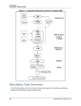
Simulation Task Overview . . . . . . . . . . . . . . . . . . . . . . . . . . . . . . . . . . . . . . . . . . . . . . . . . .
Basic Steps for Simulation. . . . . . . . . . . . . . . . . . . . . . . . . . . . . . . . . . . . . . . . . . . . . . . . . . .
Step 1 — Collecting Files and Mapping Libraries . . . . . . . . . . . . . . . . . . . . . . . . . . . . . . .
Step 2 — Compiling the Design (vlog, vcom, sccom) . . . . . . . . . . . . . . . . . . . . . . . . . . . .
Step 3 — Loading the Design for Simulation. . . . . . . . . . . . . . . . . . . . . . . . . . . . . . . . . . .
Step 4 — Simulating the Design. . . . . . . . . . . . . . . . . . . . . . . . . . . . . . . . . . . . . . . . . . . . .
Step 5 — Debugging the Design . . . . . . . . . . . . . . . . . . . . . . . . . . . . . . . . . . . . . . . . . . . .
Modes of Operation . . . . . . . . . . . . . . . . . . . . . . . . . . . . . . . . . . . . . . . . . . . . . . . . . . . . . . . .
Command Line Mode . . . . . . . . . . . . . . . . . . . . . . . . . . . . . . . . . . . . . . . . . . . . . . . . . . . . .
Batch Mode. . . . . . . . . . . . . . . . . . . . . . . . . . . . . . . . . . . . . . . . . . . . . . . . . . . . . . . . . . . . .
What is an "Object" . . . . . . . . . . . . . . . . . . . . . . . . . . . . . . . . . . . . . . . . . . . . . . . . . . . . . . . .
Graphic Interface Overview. . . . . . . . . . . . . . . . . . . . . . . . . . . . . . . . . . . . . . . . . . . . . . . . . .
Standards Supported . . . . . . . . . . . . . . . . . . . . . . . . . . . . . . . . . . . . . . . . . . . . . . . . . . . . . . .
Assumptions. . . . . . . . . . . . . . . . . . . . . . . . . . . . . . . . . . . . . . . . . . . . . . . . . . . . . . . . . . . . . .
Sections In This Document . . . . . . . . . . . . . . . . . . . . . . . . . . . . . . . . . . . . . . . . . . . . . . . . . .
Text Conventions . . . . . . . . . . . . . . . . . . . . . . . . . . . . . . . . . . . . . . . . . . . . . . . . . . . . . . . . . .
Installation Directory Pathnames. . . . . . . . . . . . . . . . . . . . . . . . . . . . . . . . . . . . . . . . . . . . . .
Where to Find Our Documentation . . . . . . . . . . . . . . . . . . . . . . . . . . . . . . . . . . . . . . . . . . . .
Mentor Graphics Support. . . . . . . . . . . . . . . . . . . . . . . . . . . . . . . . . . . . . . . . . . . . . . . . . . . .
Additional Support . . . . . . . . . . . . . . . . . . . . . . . . . . . . . . . . . . . . . . . . . . . . . . . . . . . . . . .
39
39
40
42
42
44
44
45
45
46
46
47
48
48
48
49
49
51
51
52
52
53
Chapter 2
Graphical User Interface . . . . . . . . . . . . . . . . . . . . . . . . . . . . . . . . . . . . . . . . . . . . . . . . . . . .
Design Object Icons and Their Meaning . . . . . . . . . . . . . . . . . . . . . . . . . . . . . . . . . . . . . . . .
Setting Fonts . . . . . . . . . . . . . . . . . . . . . . . . . . . . . . . . . . . . . . . . . . . . . . . . . . . . . . . . . . . .
Inline Search Bar for Text-Based Windows . . . . . . . . . . . . . . . . . . . . . . . . . . . . . . . . . . . . .
User-Defined Radices . . . . . . . . . . . . . . . . . . . . . . . . . . . . . . . . . . . . . . . . . . . . . . . . . . . . . .
Using the radix define Command . . . . . . . . . . . . . . . . . . . . . . . . . . . . . . . . . . . . . . . . . . . .
Saving and Reloading Formats and Content . . . . . . . . . . . . . . . . . . . . . . . . . . . . . . . . . . . . .
Main Window . . . . . . . . . . . . . . . . . . . . . . . . . . . . . . . . . . . . . . . . . . . . . . . . . . . . . . . . . . . .
Workspace. . . . . . . . . . . . . . . . . . . . . . . . . . . . . . . . . . . . . . . . . . . . . . . . . . . . . . . . . . . . . .
Multiple Document Interface (MDI) Frame . . . . . . . . . . . . . . . . . . . . . . . . . . . . . . . . . . . .
Organizing Windows with Tab Groups . . . . . . . . . . . . . . . . . . . . . . . . . . . . . . . . . . . . . . . . .
Navigating in the Main Window . . . . . . . . . . . . . . . . . . . . . . . . . . . . . . . . . . . . . . . . . . . . . .
Main Window Status Bar . . . . . . . . . . . . . . . . . . . . . . . . . . . . . . . . . . . . . . . . . . . . . . . . . .
Main Window Toolbar . . . . . . . . . . . . . . . . . . . . . . . . . . . . . . . . . . . . . . . . . . . . . . . . . . . .
Process Window. . . . . . . . . . . . . . . . . . . . . . . . . . . . . . . . . . . . . . . . . . . . . . . . . . . . . . . . . . .
Displaying the Process Window . . . . . . . . . . . . . . . . . . . . . . . . . . . . . . . . . . . . . . . . . . . . .
Viewing Data in the Process Window . . . . . . . . . . . . . . . . . . . . . . . . . . . . . . . . . . . . . . . .
55
57
57
58
59
59
62
62
63
65
65
66
67
68
86
87
87
ModelSim SE User’s Manual, v6.4a
3
Table of Contents
Post-Processing Mode. . . . . . . . . . . . . . . . . . . . . . . . . . . . . . . . . . . . . . . . . . . . . . . . . . . . .
Create Textual Process Report . . . . . . . . . . . . . . . . . . . . . . . . . . . . . . . . . . . . . . . . . . . . . .
Call Stack Pane . . . . . . . . . . . . . . . . . . . . . . . . . . . . . . . . . . . . . . . . . . . . . . . . . . . . . . . . . . .
Class Tree Window . . . . . . . . . . . . . . . . . . . . . . . . . . . . . . . . . . . . . . . . . . . . . . . . . . . . . . . .
Displaying the Class Tree Window . . . . . . . . . . . . . . . . . . . . . . . . . . . . . . . . . . . . . . . . . .
GUI Elements of the Class Tree Window. . . . . . . . . . . . . . . . . . . . . . . . . . . . . . . . . . . . . .
Class Graph Window . . . . . . . . . . . . . . . . . . . . . . . . . . . . . . . . . . . . . . . . . . . . . . . . . . . . . . .
Displaying the Class Graph Window . . . . . . . . . . . . . . . . . . . . . . . . . . . . . . . . . . . . . . . . .
GUI Elements of the Class Graph Window . . . . . . . . . . . . . . . . . . . . . . . . . . . . . . . . . . . .
Code Coverage Panes . . . . . . . . . . . . . . . . . . . . . . . . . . . . . . . . . . . . . . . . . . . . . . . . . . . . . .
Workspace Pane . . . . . . . . . . . . . . . . . . . . . . . . . . . . . . . . . . . . . . . . . . . . . . . . . . . . . . . . .
Missed Coverage Pane . . . . . . . . . . . . . . . . . . . . . . . . . . . . . . . . . . . . . . . . . . . . . . . . . . . .
Current Exclusions Pane . . . . . . . . . . . . . . . . . . . . . . . . . . . . . . . . . . . . . . . . . . . . . . . . . . .
Instance Coverage Pane . . . . . . . . . . . . . . . . . . . . . . . . . . . . . . . . . . . . . . . . . . . . . . . . . . .
Details Pane . . . . . . . . . . . . . . . . . . . . . . . . . . . . . . . . . . . . . . . . . . . . . . . . . . . . . . . . . . . .
Objects Pane Toggle Coverage. . . . . . . . . . . . . . . . . . . . . . . . . . . . . . . . . . . . . . . . . . . . . .
Dataflow Window . . . . . . . . . . . . . . . . . . . . . . . . . . . . . . . . . . . . . . . . . . . . . . . . . . . . . . . . .
List Window. . . . . . . . . . . . . . . . . . . . . . . . . . . . . . . . . . . . . . . . . . . . . . . . . . . . . . . . . . . . . .
Displaying the List Window . . . . . . . . . . . . . . . . . . . . . . . . . . . . . . . . . . . . . . . . . . . . . . . .
Viewing Data in the List Window . . . . . . . . . . . . . . . . . . . . . . . . . . . . . . . . . . . . . . . . . . .
GUI Elements of the List Window . . . . . . . . . . . . . . . . . . . . . . . . . . . . . . . . . . . . . . . . . . .
Locals Window . . . . . . . . . . . . . . . . . . . . . . . . . . . . . . . . . . . . . . . . . . . . . . . . . . . . . . . . . . .
Displaying the Locals Window. . . . . . . . . . . . . . . . . . . . . . . . . . . . . . . . . . . . . . . . . . . . . .
Viewing Data in the Locals Window . . . . . . . . . . . . . . . . . . . . . . . . . . . . . . . . . . . . . . . . .
GUI Elements of the Locals Window. . . . . . . . . . . . . . . . . . . . . . . . . . . . . . . . . . . . . . . . .
Memory Panes . . . . . . . . . . . . . . . . . . . . . . . . . . . . . . . . . . . . . . . . . . . . . . . . . . . . . . . . . . . .
Associative Arrays in Verilog/SystemVerilog . . . . . . . . . . . . . . . . . . . . . . . . . . . . . . . . . .
Viewing Single and Multidimensional Memories . . . . . . . . . . . . . . . . . . . . . . . . . . . . . . .
Viewing Packed Arrays . . . . . . . . . . . . . . . . . . . . . . . . . . . . . . . . . . . . . . . . . . . . . . . . . . .
Viewing Memory Contents. . . . . . . . . . . . . . . . . . . . . . . . . . . . . . . . . . . . . . . . . . . . . . . . .
Saving Memory Formats in a DO File . . . . . . . . . . . . . . . . . . . . . . . . . . . . . . . . . . . . . . . .
Direct Address Navigation . . . . . . . . . . . . . . . . . . . . . . . . . . . . . . . . . . . . . . . . . . . . . . . . .
Splitting the Memory Contents Pane . . . . . . . . . . . . . . . . . . . . . . . . . . . . . . . . . . . . . . . . .
Objects Pane. . . . . . . . . . . . . . . . . . . . . . . . . . . . . . . . . . . . . . . . . . . . . . . . . . . . . . . . . . . . . .
Filtering the Objects List . . . . . . . . . . . . . . . . . . . . . . . . . . . . . . . . . . . . . . . . . . . . . . . . . .
Filtering by Name . . . . . . . . . . . . . . . . . . . . . . . . . . . . . . . . . . . . . . . . . . . . . . . . . . . . . . . .
Filtering by Signal Type . . . . . . . . . . . . . . . . . . . . . . . . . . . . . . . . . . . . . . . . . . . . . . . . . . .
Profile Panes . . . . . . . . . . . . . . . . . . . . . . . . . . . . . . . . . . . . . . . . . . . . . . . . . . . . . . . . . . . . .
Profile Pane Columns . . . . . . . . . . . . . . . . . . . . . . . . . . . . . . . . . . . . . . . . . . . . . . . . . . . . .
Source Window . . . . . . . . . . . . . . . . . . . . . . . . . . . . . . . . . . . . . . . . . . . . . . . . . . . . . . . . . . .
Opening Source Files . . . . . . . . . . . . . . . . . . . . . . . . . . . . . . . . . . . . . . . . . . . . . . . . . . . . .
Displaying Multiple Source Files . . . . . . . . . . . . . . . . . . . . . . . . . . . . . . . . . . . . . . . . . . . .
Dragging and Dropping Objects into the Wave and List Windows . . . . . . . . . . . . . . . . . .
Setting your Context by Navigating Source Files. . . . . . . . . . . . . . . . . . . . . . . . . . . . . . . .
Debugging with Source Annotation . . . . . . . . . . . . . . . . . . . . . . . . . . . . . . . . . . . . . . . . . .
Accessing Textual Dataflow Information. . . . . . . . . . . . . . . . . . . . . . . . . . . . . . . . . . . . . .
Using Language Templates. . . . . . . . . . . . . . . . . . . . . . . . . . . . . . . . . . . . . . . . . . . . . . . . .
Setting File-Line Breakpoints with the GUI. . . . . . . . . . . . . . . . . . . . . . . . . . . . . . . . . . . .
Adding File-Line Breakpoints with the bp Command . . . . . . . . . . . . . . . . . . . . . . . . . . . .
4
91
92
93
94
95
95
96
97
98
98
99
103
105
105
105
107
109
110
111
111
112
114
114
115
115
116
118
118
119
119
120
120
120
121
122
122
123
123
124
125
126
126
127
127
130
131
133
135
136
ModelSim SE User’s Manual, v6.4a
Table of Contents
Modifying File-Line Breakpoints . . . . . . . . . . . . . . . . . . . . . . . . . . . . . . . . . . . . . . . . . . . .
Checking Object Values and Descriptions . . . . . . . . . . . . . . . . . . . . . . . . . . . . . . . . . . . . .
Marking Lines with Bookmarks . . . . . . . . . . . . . . . . . . . . . . . . . . . . . . . . . . . . . . . . . . . . .
Performing Incremental Search for Specific Code . . . . . . . . . . . . . . . . . . . . . . . . . . . . . . .
Customizing the Source Window . . . . . . . . . . . . . . . . . . . . . . . . . . . . . . . . . . . . . . . . . . . .
Verification Management Window . . . . . . . . . . . . . . . . . . . . . . . . . . . . . . . . . . . . . . . . . . . .
Browser Tab. . . . . . . . . . . . . . . . . . . . . . . . . . . . . . . . . . . . . . . . . . . . . . . . . . . . . . . . . . . . . .
Displaying the Browser Tab . . . . . . . . . . . . . . . . . . . . . . . . . . . . . . . . . . . . . . . . . . . . . . . .
Controlling the Browser Columns . . . . . . . . . . . . . . . . . . . . . . . . . . . . . . . . . . . . . . . . . . .
GUI Elements of the Browser. . . . . . . . . . . . . . . . . . . . . . . . . . . . . . . . . . . . . . . . . . . . . . .
Transcript Window . . . . . . . . . . . . . . . . . . . . . . . . . . . . . . . . . . . . . . . . . . . . . . . . . . . . . . . .
Transcript Tab. . . . . . . . . . . . . . . . . . . . . . . . . . . . . . . . . . . . . . . . . . . . . . . . . . . . . . . . . . .
Message Viewer Tab. . . . . . . . . . . . . . . . . . . . . . . . . . . . . . . . . . . . . . . . . . . . . . . . . . . . . .
Watch Pane . . . . . . . . . . . . . . . . . . . . . . . . . . . . . . . . . . . . . . . . . . . . . . . . . . . . . . . . . . . . . .
Adding Objects to the Watch Pane . . . . . . . . . . . . . . . . . . . . . . . . . . . . . . . . . . . . . . . . . . .
Expanding Objects to Show Individual Bits. . . . . . . . . . . . . . . . . . . . . . . . . . . . . . . . . . . .
Grouping and Ungrouping Objects. . . . . . . . . . . . . . . . . . . . . . . . . . . . . . . . . . . . . . . . . . .
Saving and Reloading Format Files . . . . . . . . . . . . . . . . . . . . . . . . . . . . . . . . . . . . . . . . . .
Wave Window . . . . . . . . . . . . . . . . . . . . . . . . . . . . . . . . . . . . . . . . . . . . . . . . . . . . . . . . . . . .
Wave Window Panes . . . . . . . . . . . . . . . . . . . . . . . . . . . . . . . . . . . . . . . . . . . . . . . . . . . . .
Objects You Can View in the Wave Window . . . . . . . . . . . . . . . . . . . . . . . . . . . . . . . . . .
Wave Window Toolbar. . . . . . . . . . . . . . . . . . . . . . . . . . . . . . . . . . . . . . . . . . . . . . . . . . . .
136
138
138
139
139
140
141
141
142
142
145
145
148
153
155
155
156
157
157
159
166
167
Chapter 3
Protecting Your Source Code . . . . . . . . . . . . . . . . . . . . . . . . . . . . . . . . . . . . . . . . . . . . . . . .
Usage Models for Protecting Source Code . . . . . . . . . . . . . . . . . . . . . . . . . . . . . . . . . . . . . .
Delivering IP Code with Undefined Macros . . . . . . . . . . . . . . . . . . . . . . . . . . . . . . . . . . .
Delivering IP Code with Vendor-Defined Macros . . . . . . . . . . . . . . . . . . . . . . . . . . . . . . .
Delivering Protected IP with `protect Compiler Directives . . . . . . . . . . . . . . . . . . . . . . . .
Protecting Source Code Using -nodebug. . . . . . . . . . . . . . . . . . . . . . . . . . . . . . . . . . . . . . . .
Creating an Encryption Envelope . . . . . . . . . . . . . . . . . . . . . . . . . . . . . . . . . . . . . . . . . . . . .
Protect Pragma Expressions . . . . . . . . . . . . . . . . . . . . . . . . . . . . . . . . . . . . . . . . . . . . . . . .
Compiling a Design with vlog +protect. . . . . . . . . . . . . . . . . . . . . . . . . . . . . . . . . . . . . . . . .
169
169
170
173
176
178
180
181
183
Chapter 4
Optimizing Designs with vopt . . . . . . . . . . . . . . . . . . . . . . . . . . . . . . . . . . . . . . . . . . . . . . . .
Optimization Flows . . . . . . . . . . . . . . . . . . . . . . . . . . . . . . . . . . . . . . . . . . . . . . . . . . . . . . . .
Three-Step Flow . . . . . . . . . . . . . . . . . . . . . . . . . . . . . . . . . . . . . . . . . . . . . . . . . . . . . . . . .
Two-Step Flow . . . . . . . . . . . . . . . . . . . . . . . . . . . . . . . . . . . . . . . . . . . . . . . . . . . . . . . . . .
Optimizing Parameters and Generics. . . . . . . . . . . . . . . . . . . . . . . . . . . . . . . . . . . . . . . . . . .
Optimizing Portions of your Design . . . . . . . . . . . . . . . . . . . . . . . . . . . . . . . . . . . . . . . . . . .
Simulating Designs with Several Different Testbenches . . . . . . . . . . . . . . . . . . . . . . . . . .
Alternate Optimization Flows . . . . . . . . . . . . . . . . . . . . . . . . . . . . . . . . . . . . . . . . . . . . . . . .
Simulating Designs with Read-Only Libraries . . . . . . . . . . . . . . . . . . . . . . . . . . . . . . . . . .
Creating an Environment for Optimized and Unoptimized Flows . . . . . . . . . . . . . . . . . . .
Preserving Design Visibility with the Learn Flow . . . . . . . . . . . . . . . . . . . . . . . . . . . . . . . .
Description of Learn Flow Control Files . . . . . . . . . . . . . . . . . . . . . . . . . . . . . . . . . . . . . .
Controlling Optimization from the GUI . . . . . . . . . . . . . . . . . . . . . . . . . . . . . . . . . . . . . . . .
185
185
185
188
188
190
190
191
191
192
192
194
194
ModelSim SE User’s Manual, v6.4a
5
Table of Contents
Optimization Considerations for Verilog Designs. . . . . . . . . . . . . . . . . . . . . . . . . . . . . . . . .
Design Object Visibility for Designs with PLI. . . . . . . . . . . . . . . . . . . . . . . . . . . . . . . . . .
Performing Optimization on Designs Containing SDF . . . . . . . . . . . . . . . . . . . . . . . . . . .
Reporting on Gate-Level Optimizations. . . . . . . . . . . . . . . . . . . . . . . . . . . . . . . . . . . . . . .
Using Pre-Compiled Libraries . . . . . . . . . . . . . . . . . . . . . . . . . . . . . . . . . . . . . . . . . . . . . .
Event Order and Optimized Designs . . . . . . . . . . . . . . . . . . . . . . . . . . . . . . . . . . . . . . . . .
Timing Checks in Optimized Designs . . . . . . . . . . . . . . . . . . . . . . . . . . . . . . . . . . . . . . . .
195
195
196
197
198
198
198
Chapter 5
Projects. . . . . . . . . . . . . . . . . . . . . . . . . . . . . . . . . . . . . . . . . . . . . . . . . . . . . . . . . . . . . . . . . . .
What are Projects? . . . . . . . . . . . . . . . . . . . . . . . . . . . . . . . . . . . . . . . . . . . . . . . . . . . . . . . . .
What are the Benefits of Projects? . . . . . . . . . . . . . . . . . . . . . . . . . . . . . . . . . . . . . . . . . . .
Project Conversion Between Versions . . . . . . . . . . . . . . . . . . . . . . . . . . . . . . . . . . . . . . . .
Getting Started with Projects . . . . . . . . . . . . . . . . . . . . . . . . . . . . . . . . . . . . . . . . . . . . . . . . .
Step 1 — Creating a New Project . . . . . . . . . . . . . . . . . . . . . . . . . . . . . . . . . . . . . . . . . . . .
Step 2 — Adding Items to the Project . . . . . . . . . . . . . . . . . . . . . . . . . . . . . . . . . . . . . . . .
Step 3 — Compiling the Files. . . . . . . . . . . . . . . . . . . . . . . . . . . . . . . . . . . . . . . . . . . . . . .
Step 4 — Simulating a Design . . . . . . . . . . . . . . . . . . . . . . . . . . . . . . . . . . . . . . . . . . . . . .
Other Basic Project Operations. . . . . . . . . . . . . . . . . . . . . . . . . . . . . . . . . . . . . . . . . . . . . .
The Project Tab . . . . . . . . . . . . . . . . . . . . . . . . . . . . . . . . . . . . . . . . . . . . . . . . . . . . . . . . . . .
Sorting the List . . . . . . . . . . . . . . . . . . . . . . . . . . . . . . . . . . . . . . . . . . . . . . . . . . . . . . . . . .
Creating a Simulation Configuration . . . . . . . . . . . . . . . . . . . . . . . . . . . . . . . . . . . . . . . . . . .
Optimization Configurations . . . . . . . . . . . . . . . . . . . . . . . . . . . . . . . . . . . . . . . . . . . . . . .
Organizing Projects with Folders. . . . . . . . . . . . . . . . . . . . . . . . . . . . . . . . . . . . . . . . . . . . . .
Adding a Folder . . . . . . . . . . . . . . . . . . . . . . . . . . . . . . . . . . . . . . . . . . . . . . . . . . . . . . . . .
Specifying File Properties and Project Settings. . . . . . . . . . . . . . . . . . . . . . . . . . . . . . . . . . .
File Compilation Properties . . . . . . . . . . . . . . . . . . . . . . . . . . . . . . . . . . . . . . . . . . . . . . . .
Project Settings . . . . . . . . . . . . . . . . . . . . . . . . . . . . . . . . . . . . . . . . . . . . . . . . . . . . . . . . . .
Accessing Projects from the Command Line. . . . . . . . . . . . . . . . . . . . . . . . . . . . . . . . . . . . .
199
199
199
200
200
201
202
203
206
208
208
209
209
211
211
211
213
213
215
216
Chapter 6
Design Libraries . . . . . . . . . . . . . . . . . . . . . . . . . . . . . . . . . . . . . . . . . . . . . . . . . . . . . . . . . . .
Design Library Overview . . . . . . . . . . . . . . . . . . . . . . . . . . . . . . . . . . . . . . . . . . . . . . . . . . .
Design Unit Information . . . . . . . . . . . . . . . . . . . . . . . . . . . . . . . . . . . . . . . . . . . . . . . . . . .
Working Library Versus Resource Libraries . . . . . . . . . . . . . . . . . . . . . . . . . . . . . . . . . . .
Archives . . . . . . . . . . . . . . . . . . . . . . . . . . . . . . . . . . . . . . . . . . . . . . . . . . . . . . . . . . . . . . .
Working with Design Libraries . . . . . . . . . . . . . . . . . . . . . . . . . . . . . . . . . . . . . . . . . . . . . . .
Creating a Library . . . . . . . . . . . . . . . . . . . . . . . . . . . . . . . . . . . . . . . . . . . . . . . . . . . . . . . .
Managing Library Contents . . . . . . . . . . . . . . . . . . . . . . . . . . . . . . . . . . . . . . . . . . . . . . . .
Assigning a Logical Name to a Design Library . . . . . . . . . . . . . . . . . . . . . . . . . . . . . . . . .
Moving a Library . . . . . . . . . . . . . . . . . . . . . . . . . . . . . . . . . . . . . . . . . . . . . . . . . . . . . . . .
Setting Up Libraries for Group Use . . . . . . . . . . . . . . . . . . . . . . . . . . . . . . . . . . . . . . . . . .
Specifying Resource Libraries. . . . . . . . . . . . . . . . . . . . . . . . . . . . . . . . . . . . . . . . . . . . . . . .
Verilog Resource Libraries . . . . . . . . . . . . . . . . . . . . . . . . . . . . . . . . . . . . . . . . . . . . . . . . .
VHDL Resource Libraries . . . . . . . . . . . . . . . . . . . . . . . . . . . . . . . . . . . . . . . . . . . . . . . . .
Predefined Libraries . . . . . . . . . . . . . . . . . . . . . . . . . . . . . . . . . . . . . . . . . . . . . . . . . . . . . .
Alternate IEEE Libraries Supplied . . . . . . . . . . . . . . . . . . . . . . . . . . . . . . . . . . . . . . . . . . .
Rebuilding Supplied Libraries . . . . . . . . . . . . . . . . . . . . . . . . . . . . . . . . . . . . . . . . . . . . . .
217
217
217
217
218
218
219
219
221
222
222
223
223
223
223
224
224
6
ModelSim SE User’s Manual, v6.4a
Table of Contents
Regenerating Your Design Libraries . . . . . . . . . . . . . . . . . . . . . . . . . . . . . . . . . . . . . . . . .
Maintaining 32- and 64-bit Versions in the Same Library . . . . . . . . . . . . . . . . . . . . . . . . .
Importing FPGA Libraries. . . . . . . . . . . . . . . . . . . . . . . . . . . . . . . . . . . . . . . . . . . . . . . . . . .
Protecting Source Code . . . . . . . . . . . . . . . . . . . . . . . . . . . . . . . . . . . . . . . . . . . . . . . . . . . . .
225
225
226
227
Chapter 7
VHDL Simulation . . . . . . . . . . . . . . . . . . . . . . . . . . . . . . . . . . . . . . . . . . . . . . . . . . . . . . . . . .
Basic VHDL Flow . . . . . . . . . . . . . . . . . . . . . . . . . . . . . . . . . . . . . . . . . . . . . . . . . . . . . . .
Compiling VHDL Files . . . . . . . . . . . . . . . . . . . . . . . . . . . . . . . . . . . . . . . . . . . . . . . . . . . . .
Creating a Design Library for VHDL. . . . . . . . . . . . . . . . . . . . . . . . . . . . . . . . . . . . . . . . .
Invoking the VHDL Compiler . . . . . . . . . . . . . . . . . . . . . . . . . . . . . . . . . . . . . . . . . . . . . .
Dependency Checking . . . . . . . . . . . . . . . . . . . . . . . . . . . . . . . . . . . . . . . . . . . . . . . . . . . .
Range and Index Checking . . . . . . . . . . . . . . . . . . . . . . . . . . . . . . . . . . . . . . . . . . . . . . . . .
Subprogram Inlining . . . . . . . . . . . . . . . . . . . . . . . . . . . . . . . . . . . . . . . . . . . . . . . . . . . . . .
Differences Between Language Versions. . . . . . . . . . . . . . . . . . . . . . . . . . . . . . . . . . . . . .
Simulating VHDL Designs . . . . . . . . . . . . . . . . . . . . . . . . . . . . . . . . . . . . . . . . . . . . . . . . . .
Simulator Resolution Limit (VHDL) . . . . . . . . . . . . . . . . . . . . . . . . . . . . . . . . . . . . . . . . .
Default Binding. . . . . . . . . . . . . . . . . . . . . . . . . . . . . . . . . . . . . . . . . . . . . . . . . . . . . . . . . .
Delta Delays . . . . . . . . . . . . . . . . . . . . . . . . . . . . . . . . . . . . . . . . . . . . . . . . . . . . . . . . . . . .
Using the TextIO Package . . . . . . . . . . . . . . . . . . . . . . . . . . . . . . . . . . . . . . . . . . . . . . . . . . .
Syntax for File Declaration. . . . . . . . . . . . . . . . . . . . . . . . . . . . . . . . . . . . . . . . . . . . . . . . .
Using STD_INPUT and STD_OUTPUT Within the Tool . . . . . . . . . . . . . . . . . . . . . . . . .
TextIO Implementation Issues. . . . . . . . . . . . . . . . . . . . . . . . . . . . . . . . . . . . . . . . . . . . . . . .
Writing Strings and Aggregates . . . . . . . . . . . . . . . . . . . . . . . . . . . . . . . . . . . . . . . . . . . . .
Reading and Writing Hexadecimal Numbers . . . . . . . . . . . . . . . . . . . . . . . . . . . . . . . . . . .
Dangling Pointers . . . . . . . . . . . . . . . . . . . . . . . . . . . . . . . . . . . . . . . . . . . . . . . . . . . . . . . .
The ENDLINE Function. . . . . . . . . . . . . . . . . . . . . . . . . . . . . . . . . . . . . . . . . . . . . . . . . . .
The ENDFILE Function . . . . . . . . . . . . . . . . . . . . . . . . . . . . . . . . . . . . . . . . . . . . . . . . . . .
Using Alternative Input/Output Files . . . . . . . . . . . . . . . . . . . . . . . . . . . . . . . . . . . . . . . . .
Flushing the TEXTIO Buffer . . . . . . . . . . . . . . . . . . . . . . . . . . . . . . . . . . . . . . . . . . . . . . .
Providing Stimulus . . . . . . . . . . . . . . . . . . . . . . . . . . . . . . . . . . . . . . . . . . . . . . . . . . . . . . .
VITAL Specification and Source Code . . . . . . . . . . . . . . . . . . . . . . . . . . . . . . . . . . . . . . . . .
VITAL Packages . . . . . . . . . . . . . . . . . . . . . . . . . . . . . . . . . . . . . . . . . . . . . . . . . . . . . . . . . .
VITAL Compliance . . . . . . . . . . . . . . . . . . . . . . . . . . . . . . . . . . . . . . . . . . . . . . . . . . . . . . . .
VITAL Compliance Checking . . . . . . . . . . . . . . . . . . . . . . . . . . . . . . . . . . . . . . . . . . . . . .
VITAL Compliance Warnings . . . . . . . . . . . . . . . . . . . . . . . . . . . . . . . . . . . . . . . . . . . . . .
Compiling and Simulating with Accelerated VITAL Packages . . . . . . . . . . . . . . . . . . . . . .
Compiler Options for VITAL Optimization . . . . . . . . . . . . . . . . . . . . . . . . . . . . . . . . . . . .
Util Package . . . . . . . . . . . . . . . . . . . . . . . . . . . . . . . . . . . . . . . . . . . . . . . . . . . . . . . . . . . . . .
get_resolution . . . . . . . . . . . . . . . . . . . . . . . . . . . . . . . . . . . . . . . . . . . . . . . . . . . . . . . . . . .
init_signal_driver() . . . . . . . . . . . . . . . . . . . . . . . . . . . . . . . . . . . . . . . . . . . . . . . . . . . . . . .
init_signal_spy() . . . . . . . . . . . . . . . . . . . . . . . . . . . . . . . . . . . . . . . . . . . . . . . . . . . . . . . . .
signal_force() . . . . . . . . . . . . . . . . . . . . . . . . . . . . . . . . . . . . . . . . . . . . . . . . . . . . . . . . . . .
signal_release() . . . . . . . . . . . . . . . . . . . . . . . . . . . . . . . . . . . . . . . . . . . . . . . . . . . . . . . . . .
to_real(). . . . . . . . . . . . . . . . . . . . . . . . . . . . . . . . . . . . . . . . . . . . . . . . . . . . . . . . . . . . . . . .
to_time() . . . . . . . . . . . . . . . . . . . . . . . . . . . . . . . . . . . . . . . . . . . . . . . . . . . . . . . . . . . . . . .
Foreign Language Interface . . . . . . . . . . . . . . . . . . . . . . . . . . . . . . . . . . . . . . . . . . . . . . . . . .
Modeling Memory . . . . . . . . . . . . . . . . . . . . . . . . . . . . . . . . . . . . . . . . . . . . . . . . . . . . . . . . .
229
229
229
229
230
230
230
230
231
234
235
235
236
239
239
240
240
240
241
242
242
242
242
243
243
243
244
244
244
245
245
246
246
246
247
247
247
248
248
249
249
250
ModelSim SE User’s Manual, v6.4a
7
Table of Contents
VHDL87 and VHDL93 Example . . . . . . . . . . . . . . . . . . . . . . . . . . . . . . . . . . . . . . . . . . . .
VHDL02 example. . . . . . . . . . . . . . . . . . . . . . . . . . . . . . . . . . . . . . . . . . . . . . . . . . . . . . . .
Affecting Performance by Cancelling Scheduled Events . . . . . . . . . . . . . . . . . . . . . . . . . . .
Converting an Integer Into a bit_vector . . . . . . . . . . . . . . . . . . . . . . . . . . . . . . . . . . . . . . . . .
251
254
258
258
Chapter 8
Verilog and SystemVerilog Simulation. . . . . . . . . . . . . . . . . . . . . . . . . . . . . . . . . . . . . . . . .
Terminology. . . . . . . . . . . . . . . . . . . . . . . . . . . . . . . . . . . . . . . . . . . . . . . . . . . . . . . . . . . . . .
Basic Verilog Flow . . . . . . . . . . . . . . . . . . . . . . . . . . . . . . . . . . . . . . . . . . . . . . . . . . . . . . . .
Compiling Verilog Files . . . . . . . . . . . . . . . . . . . . . . . . . . . . . . . . . . . . . . . . . . . . . . . . . . . .
Creating a Working Library . . . . . . . . . . . . . . . . . . . . . . . . . . . . . . . . . . . . . . . . . . . . . . . .
Invoking the Verilog Compiler. . . . . . . . . . . . . . . . . . . . . . . . . . . . . . . . . . . . . . . . . . . . . .
Incremental Compilation . . . . . . . . . . . . . . . . . . . . . . . . . . . . . . . . . . . . . . . . . . . . . . . . . .
Library Usage . . . . . . . . . . . . . . . . . . . . . . . . . . . . . . . . . . . . . . . . . . . . . . . . . . . . . . . . . . .
SystemVerilog Multi-File Compilation Issues . . . . . . . . . . . . . . . . . . . . . . . . . . . . . . . . . .
Verilog-XL Compatible Compiler Arguments . . . . . . . . . . . . . . . . . . . . . . . . . . . . . . . . . .
Verilog-XL uselib Compiler Directive . . . . . . . . . . . . . . . . . . . . . . . . . . . . . . . . . . . . . . . .
Verilog Configurations . . . . . . . . . . . . . . . . . . . . . . . . . . . . . . . . . . . . . . . . . . . . . . . . . . . .
Verilog Generate Statements . . . . . . . . . . . . . . . . . . . . . . . . . . . . . . . . . . . . . . . . . . . . . . .
Initializing Registers and Memories . . . . . . . . . . . . . . . . . . . . . . . . . . . . . . . . . . . . . . . . . .
Simulating Verilog Designs. . . . . . . . . . . . . . . . . . . . . . . . . . . . . . . . . . . . . . . . . . . . . . . . . .
Simulator Resolution Limit (Verilog). . . . . . . . . . . . . . . . . . . . . . . . . . . . . . . . . . . . . . . . .
Event Ordering in Verilog Designs. . . . . . . . . . . . . . . . . . . . . . . . . . . . . . . . . . . . . . . . . . .
Debugging Event Order Issues . . . . . . . . . . . . . . . . . . . . . . . . . . . . . . . . . . . . . . . . . . . . . .
Debugging Signal Segmentation Violations. . . . . . . . . . . . . . . . . . . . . . . . . . . . . . . . . . . .
Negative Timing Checks. . . . . . . . . . . . . . . . . . . . . . . . . . . . . . . . . . . . . . . . . . . . . . . . . . .
Verilog-XL Compatible Simulator Arguments . . . . . . . . . . . . . . . . . . . . . . . . . . . . . . . . .
Using Escaped Identifiers . . . . . . . . . . . . . . . . . . . . . . . . . . . . . . . . . . . . . . . . . . . . . . . . . .
Cell Libraries . . . . . . . . . . . . . . . . . . . . . . . . . . . . . . . . . . . . . . . . . . . . . . . . . . . . . . . . . . . . .
SDF Timing Annotation . . . . . . . . . . . . . . . . . . . . . . . . . . . . . . . . . . . . . . . . . . . . . . . . . . .
Delay Modes . . . . . . . . . . . . . . . . . . . . . . . . . . . . . . . . . . . . . . . . . . . . . . . . . . . . . . . . . . . .
System Tasks and Functions . . . . . . . . . . . . . . . . . . . . . . . . . . . . . . . . . . . . . . . . . . . . . . . . .
IEEE Std 1364 System Tasks and Functions . . . . . . . . . . . . . . . . . . . . . . . . . . . . . . . . . . .
SystemVerilog System Tasks and Functions . . . . . . . . . . . . . . . . . . . . . . . . . . . . . . . . . . .
System Tasks and Functions Specific to the Tool . . . . . . . . . . . . . . . . . . . . . . . . . . . . . . .
Verilog-XL Compatible System Tasks and Functions . . . . . . . . . . . . . . . . . . . . . . . . . . . .
Compiler Directives . . . . . . . . . . . . . . . . . . . . . . . . . . . . . . . . . . . . . . . . . . . . . . . . . . . . . . . .
IEEE Std 1364 Compiler Directives . . . . . . . . . . . . . . . . . . . . . . . . . . . . . . . . . . . . . . . . . .
Compiler Directives for vlog . . . . . . . . . . . . . . . . . . . . . . . . . . . . . . . . . . . . . . . . . . . . . . .
Verilog-XL Compatible Compiler Directives . . . . . . . . . . . . . . . . . . . . . . . . . . . . . . . . . .
Sparse Memory Modeling . . . . . . . . . . . . . . . . . . . . . . . . . . . . . . . . . . . . . . . . . . . . . . . . . . .
Manually Marking Sparse Memories . . . . . . . . . . . . . . . . . . . . . . . . . . . . . . . . . . . . . . . . .
Automatically Enabling Sparse Memories . . . . . . . . . . . . . . . . . . . . . . . . . . . . . . . . . . . . .
Combining Automatic and Manual Modes. . . . . . . . . . . . . . . . . . . . . . . . . . . . . . . . . . . . .
Priority of Sparse Memories . . . . . . . . . . . . . . . . . . . . . . . . . . . . . . . . . . . . . . . . . . . . . . . .
Determining Which Memories Were Implemented as Sparse . . . . . . . . . . . . . . . . . . . . . .
Verilog PLI/VPI and SystemVerilog DPI . . . . . . . . . . . . . . . . . . . . . . . . . . . . . . . . . . . . . . .
261
261
261
261
262
262
263
265
267
268
269
272
273
274
276
276
279
282
284
286
295
295
297
297
297
298
299
301
302
306
309
310
310
312
313
313
314
314
314
314
315
8
ModelSim SE User’s Manual, v6.4a
Table of Contents
Chapter 9
SystemC Simulation . . . . . . . . . . . . . . . . . . . . . . . . . . . . . . . . . . . . . . . . . . . . . . . . . . . . . . . .
Supported Platforms and Compiler Versions . . . . . . . . . . . . . . . . . . . . . . . . . . . . . . . . . . . .
Building gcc with Custom Configuration Options . . . . . . . . . . . . . . . . . . . . . . . . . . . . . . .
Usage Flow for SystemC-Only Designs . . . . . . . . . . . . . . . . . . . . . . . . . . . . . . . . . . . . . . . .
Binding to Verilog or SystemVerilog Designs . . . . . . . . . . . . . . . . . . . . . . . . . . . . . . . . . . .
Limitations of Bind Support for SystemC . . . . . . . . . . . . . . . . . . . . . . . . . . . . . . . . . . . . .
Compiling SystemC Files . . . . . . . . . . . . . . . . . . . . . . . . . . . . . . . . . . . . . . . . . . . . . . . . . . .
Creating a Design Library for SystemC . . . . . . . . . . . . . . . . . . . . . . . . . . . . . . . . . . . . . . .
Invoking the SystemC Compiler. . . . . . . . . . . . . . . . . . . . . . . . . . . . . . . . . . . . . . . . . . . . .
Compiling Optimized and/or Debug Code . . . . . . . . . . . . . . . . . . . . . . . . . . . . . . . . . . . . .
Specifying an Alternate g++ Installation . . . . . . . . . . . . . . . . . . . . . . . . . . . . . . . . . . . . . .
Maintaining Portability Between OSCI and the Simulator. . . . . . . . . . . . . . . . . . . . . . . . .
Switching Platforms and Compilation . . . . . . . . . . . . . . . . . . . . . . . . . . . . . . . . . . . . . . . .
Using sccom in Addition to the Raw C++ Compiler . . . . . . . . . . . . . . . . . . . . . . . . . . . . .
Compiling Changed Files Only (Incremental Compilation). . . . . . . . . . . . . . . . . . . . . . . .
Issues with C++ Templates. . . . . . . . . . . . . . . . . . . . . . . . . . . . . . . . . . . . . . . . . . . . . . . . .
Linking the Compiled Source . . . . . . . . . . . . . . . . . . . . . . . . . . . . . . . . . . . . . . . . . . . . . . . .
Simulating SystemC Designs. . . . . . . . . . . . . . . . . . . . . . . . . . . . . . . . . . . . . . . . . . . . . . . . .
Loading the Design . . . . . . . . . . . . . . . . . . . . . . . . . . . . . . . . . . . . . . . . . . . . . . . . . . . . . . .
Running Simulation . . . . . . . . . . . . . . . . . . . . . . . . . . . . . . . . . . . . . . . . . . . . . . . . . . . . . .
SystemC Time Unit and Simulator Resolution. . . . . . . . . . . . . . . . . . . . . . . . . . . . . . . . . .
Initialization and Cleanup of SystemC State-Based Code . . . . . . . . . . . . . . . . . . . . . . . . .
Debugging the Design . . . . . . . . . . . . . . . . . . . . . . . . . . . . . . . . . . . . . . . . . . . . . . . . . . . . . .
Viewable SystemC Types . . . . . . . . . . . . . . . . . . . . . . . . . . . . . . . . . . . . . . . . . . . . . . . . . .
Viewable SystemC Objects. . . . . . . . . . . . . . . . . . . . . . . . . . . . . . . . . . . . . . . . . . . . . . . . .
Waveform Compare with SystemC . . . . . . . . . . . . . . . . . . . . . . . . . . . . . . . . . . . . . . . . . .
Debugging Source-Level Code. . . . . . . . . . . . . . . . . . . . . . . . . . . . . . . . . . . . . . . . . . . . . .
SystemC Object and Type Display . . . . . . . . . . . . . . . . . . . . . . . . . . . . . . . . . . . . . . . . . . . .
Support for Globals and Statics . . . . . . . . . . . . . . . . . . . . . . . . . . . . . . . . . . . . . . . . . . . . .
Support for Aggregates . . . . . . . . . . . . . . . . . . . . . . . . . . . . . . . . . . . . . . . . . . . . . . . . . . . .
SystemC Dynamic Module Array. . . . . . . . . . . . . . . . . . . . . . . . . . . . . . . . . . . . . . . . . . . .
Viewing FIFOs . . . . . . . . . . . . . . . . . . . . . . . . . . . . . . . . . . . . . . . . . . . . . . . . . . . . . . . . . .
Viewing SystemC Memories . . . . . . . . . . . . . . . . . . . . . . . . . . . . . . . . . . . . . . . . . . . . . . .
Properly Recognizing Derived Module Class Pointers . . . . . . . . . . . . . . . . . . . . . . . . . . .
Custom Debugging of SystemC Channels and Variables. . . . . . . . . . . . . . . . . . . . . . . . . .
Modifying SystemC Source Code . . . . . . . . . . . . . . . . . . . . . . . . . . . . . . . . . . . . . . . . . . .
Code Modification Examples . . . . . . . . . . . . . . . . . . . . . . . . . . . . . . . . . . . . . . . . . . . . . . .
Using sc_main as Top Level. . . . . . . . . . . . . . . . . . . . . . . . . . . . . . . . . . . . . . . . . . . . . . . .
Differences Between the Simulator and OSCI . . . . . . . . . . . . . . . . . . . . . . . . . . . . . . . . . . .
Fixed-Point Types. . . . . . . . . . . . . . . . . . . . . . . . . . . . . . . . . . . . . . . . . . . . . . . . . . . . . . . .
Algorithmic C Datatype Support . . . . . . . . . . . . . . . . . . . . . . . . . . . . . . . . . . . . . . . . . . . .
Support for cin . . . . . . . . . . . . . . . . . . . . . . . . . . . . . . . . . . . . . . . . . . . . . . . . . . . . . . . . . .
OSCI 2.2 Feature Implementation Details. . . . . . . . . . . . . . . . . . . . . . . . . . . . . . . . . . . . . . .
Support for OSCI TLM Library . . . . . . . . . . . . . . . . . . . . . . . . . . . . . . . . . . . . . . . . . . . . .
Phase Callback . . . . . . . . . . . . . . . . . . . . . . . . . . . . . . . . . . . . . . . . . . . . . . . . . . . . . . . . . .
Accessing Command-Line Arguments . . . . . . . . . . . . . . . . . . . . . . . . . . . . . . . . . . . . . . . .
sc_stop Behavior. . . . . . . . . . . . . . . . . . . . . . . . . . . . . . . . . . . . . . . . . . . . . . . . . . . . . . . . .
ModelSim SE User’s Manual, v6.4a
317
317
318
319
320
320
320
320
321
321
322
322
323
323
324
326
332
332
332
333
333
335
336
336
337
338
338
342
342
343
344
344
345
345
347
352
353
355
358
359
360
360
361
361
361
361
362
9
Table of Contents
Construction Parameters for SystemC Types . . . . . . . . . . . . . . . . . . . . . . . . . . . . . . . . . . .
Troubleshooting SystemC Errors. . . . . . . . . . . . . . . . . . . . . . . . . . . . . . . . . . . . . . . . . . . . . .
Unexplained Behaviors During Loading or Runtime . . . . . . . . . . . . . . . . . . . . . . . . . . . . .
Errors During Loading . . . . . . . . . . . . . . . . . . . . . . . . . . . . . . . . . . . . . . . . . . . . . . . . . . . .
362
364
364
365
Chapter 10
Mixed-Language Simulation . . . . . . . . . . . . . . . . . . . . . . . . . . . . . . . . . . . . . . . . . . . . . . . . .
Basic Mixed-Language Flow. . . . . . . . . . . . . . . . . . . . . . . . . . . . . . . . . . . . . . . . . . . . . . . . .
Separate Compilers with Common Design Libraries . . . . . . . . . . . . . . . . . . . . . . . . . . . . . .
Access Limitations in Mixed-Language Designs . . . . . . . . . . . . . . . . . . . . . . . . . . . . . . . .
Using SystemVerilog bind Construct in Mixed-Language Designs . . . . . . . . . . . . . . . . . . .
Syntax of bind Statement . . . . . . . . . . . . . . . . . . . . . . . . . . . . . . . . . . . . . . . . . . . . . . . . . .
What Can Be Bound . . . . . . . . . . . . . . . . . . . . . . . . . . . . . . . . . . . . . . . . . . . . . . . . . . . . . .
Mapping of Types . . . . . . . . . . . . . . . . . . . . . . . . . . . . . . . . . . . . . . . . . . . . . . . . . . . . . . . .
Using SV Bind With or Without vopt . . . . . . . . . . . . . . . . . . . . . . . . . . . . . . . . . . . . . . . .
Binding to VHDL Enumerated Types . . . . . . . . . . . . . . . . . . . . . . . . . . . . . . . . . . . . . . . .
Binding to a VHDL Instance . . . . . . . . . . . . . . . . . . . . . . . . . . . . . . . . . . . . . . . . . . . . . . .
Limitations to Bind Support for SystemC . . . . . . . . . . . . . . . . . . . . . . . . . . . . . . . . . . . . .
Optimizing Mixed Designs . . . . . . . . . . . . . . . . . . . . . . . . . . . . . . . . . . . . . . . . . . . . . . . . . .
Simulator Resolution Limit . . . . . . . . . . . . . . . . . . . . . . . . . . . . . . . . . . . . . . . . . . . . . . . . . .
Runtime Modeling Semantics . . . . . . . . . . . . . . . . . . . . . . . . . . . . . . . . . . . . . . . . . . . . . . . .
Hierarchical References to SystemVerilog. . . . . . . . . . . . . . . . . . . . . . . . . . . . . . . . . . . . .
Hierarchical References In Mixed HDL and SystemC Designs. . . . . . . . . . . . . . . . . . . . .
Signal Connections Between Mixed HDL and SystemC Designs . . . . . . . . . . . . . . . . . . .
Mapping Data Types . . . . . . . . . . . . . . . . . . . . . . . . . . . . . . . . . . . . . . . . . . . . . . . . . . . . . . .
Verilog and SystemVerilog to VHDL Mappings . . . . . . . . . . . . . . . . . . . . . . . . . . . . . . . .
VHDL To Verilog and SystemVerilog Mappings . . . . . . . . . . . . . . . . . . . . . . . . . . . . . . .
Verilog or SystemVerilog and SystemC Signal Interaction And Mappings . . . . . . . . . . .
VHDL and SystemC Signal Interaction And Mappings. . . . . . . . . . . . . . . . . . . . . . . . . . .
VHDL Instantiating Verilog or SystemVerilog. . . . . . . . . . . . . . . . . . . . . . . . . . . . . . . . . . .
Verilog/SystemVerilog Instantiation Criteria Within VHDL. . . . . . . . . . . . . . . . . . . . . . .
Component Declaration for VHDL Instantiating Verilog . . . . . . . . . . . . . . . . . . . . . . . . .
vgencomp Component Declaration when VHDL Instantiates Verilog . . . . . . . . . . . . . . .
Modules with Unnamed Ports. . . . . . . . . . . . . . . . . . . . . . . . . . . . . . . . . . . . . . . . . . . . . . .
Verilog or SystemVerilog Instantiating VHDL. . . . . . . . . . . . . . . . . . . . . . . . . . . . . . . . . . .
VHDL Instantiation Criteria Within Verilog . . . . . . . . . . . . . . . . . . . . . . . . . . . . . . . . . . .
Entity and Architecture Names and Escaped Identifiers . . . . . . . . . . . . . . . . . . . . . . . . . .
Named Port Associations . . . . . . . . . . . . . . . . . . . . . . . . . . . . . . . . . . . . . . . . . . . . . . . . . .
Generic Associations . . . . . . . . . . . . . . . . . . . . . . . . . . . . . . . . . . . . . . . . . . . . . . . . . . . . .
SDF Annotation . . . . . . . . . . . . . . . . . . . . . . . . . . . . . . . . . . . . . . . . . . . . . . . . . . . . . . . . .
Sharing User-Defined Types . . . . . . . . . . . . . . . . . . . . . . . . . . . . . . . . . . . . . . . . . . . . . . . . .
SystemC Instantiating Verilog or SystemVerilog . . . . . . . . . . . . . . . . . . . . . . . . . . . . . . . . .
Verilog Instantiation Criteria Within SystemC. . . . . . . . . . . . . . . . . . . . . . . . . . . . . . . . . .
SystemC Foreign Module (Verilog) Declaration . . . . . . . . . . . . . . . . . . . . . . . . . . . . . . . .
Parameter Support for SystemC Instantiating Verilog . . . . . . . . . . . . . . . . . . . . . . . . . . . .
Verilog or SystemVerilog Instantiating SystemC . . . . . . . . . . . . . . . . . . . . . . . . . . . . . . . . .
SystemC Instantiation Criteria for Verilog . . . . . . . . . . . . . . . . . . . . . . . . . . . . . . . . . . . . .
Exporting SystemC Modules for Verilog . . . . . . . . . . . . . . . . . . . . . . . . . . . . . . . . . . . . . .
369
369
370
370
370
371
371
372
373
374
376
379
379
379
380
380
381
382
383
384
388
390
398
404
405
405
406
407
408
408
408
409
409
409
409
414
414
415
416
421
421
421
10
ModelSim SE User’s Manual, v6.4a
Table of Contents
Parameter Support for Verilog Instantiating SystemC . . . . . . . . . . . . . . . . . . . . . . . . . . . .
SystemC Instantiating VHDL . . . . . . . . . . . . . . . . . . . . . . . . . . . . . . . . . . . . . . . . . . . . . . . .
VHDL Instantiation Criteria Within SystemC . . . . . . . . . . . . . . . . . . . . . . . . . . . . . . . . . .
SystemC Foreign Module (VHDL) Declaration. . . . . . . . . . . . . . . . . . . . . . . . . . . . . . . . .
Generic Support for SystemC Instantiating VHDL . . . . . . . . . . . . . . . . . . . . . . . . . . . . . .
VHDL Instantiating SystemC . . . . . . . . . . . . . . . . . . . . . . . . . . . . . . . . . . . . . . . . . . . . . . . .
SystemC Instantiation Criteria for VHDL . . . . . . . . . . . . . . . . . . . . . . . . . . . . . . . . . . . . .
Component Declaration for VHDL Instantiating SystemC . . . . . . . . . . . . . . . . . . . . . . . .
vgencomp Component Declaration when VHDL Instantiates SystemC . . . . . . . . . . . . . .
Exporting SystemC Modules for VHDL . . . . . . . . . . . . . . . . . . . . . . . . . . . . . . . . . . . . . .
Generic Support for VHDL Instantiating SystemC . . . . . . . . . . . . . . . . . . . . . . . . . . . . . .
SystemC Procedural Interface to SystemVerilog . . . . . . . . . . . . . . . . . . . . . . . . . . . . . . . . .
Definition of Terms. . . . . . . . . . . . . . . . . . . . . . . . . . . . . . . . . . . . . . . . . . . . . . . . . . . . . . .
SystemC DPI Usage Flow . . . . . . . . . . . . . . . . . . . . . . . . . . . . . . . . . . . . . . . . . . . . . . . . .
SystemC Import Functions . . . . . . . . . . . . . . . . . . . . . . . . . . . . . . . . . . . . . . . . . . . . . . . . .
Calling SystemVerilog Export Tasks / Functions from SystemC . . . . . . . . . . . . . . . . . . .
SystemC Data Type Support in SystemVerilog DPI . . . . . . . . . . . . . . . . . . . . . . . . . . . . .
SystemC Function Prototype Header File (sc_dpiheader.h). . . . . . . . . . . . . . . . . . . . . . . .
Support for Multiple SystemVerilog Libraries . . . . . . . . . . . . . . . . . . . . . . . . . . . . . . . . . .
SystemC DPI Usage Example . . . . . . . . . . . . . . . . . . . . . . . . . . . . . . . . . . . . . . . . . . . . . .
422
424
424
425
426
431
431
431
432
432
433
433
433
434
434
438
438
441
441
442
Chapter 11
Advanced Simulation Techniques . . . . . . . . . . . . . . . . . . . . . . . . . . . . . . . . . . . . . . . . . . . . .
Checkpointing and Restoring Simulations . . . . . . . . . . . . . . . . . . . . . . . . . . . . . . . . . . . . . .
Checkpoint File Contents . . . . . . . . . . . . . . . . . . . . . . . . . . . . . . . . . . . . . . . . . . . . . . . . . .
Controlling Checkpoint File Compression . . . . . . . . . . . . . . . . . . . . . . . . . . . . . . . . . . . . .
The Difference Between Checkpoint/Restore and Restart . . . . . . . . . . . . . . . . . . . . . . . . .
Using Macros with Restart and Checkpoint/Restore . . . . . . . . . . . . . . . . . . . . . . . . . . . . .
Checkpointing Foreign C Code That Works with Heap Memory . . . . . . . . . . . . . . . . . . .
Checkpointing a Running Simulation. . . . . . . . . . . . . . . . . . . . . . . . . . . . . . . . . . . . . . . . .
Simulating with an Elaboration File . . . . . . . . . . . . . . . . . . . . . . . . . . . . . . . . . . . . . . . . . . .
Why an Elaboration File? . . . . . . . . . . . . . . . . . . . . . . . . . . . . . . . . . . . . . . . . . . . . . . . . . .
Elaboration File Flow . . . . . . . . . . . . . . . . . . . . . . . . . . . . . . . . . . . . . . . . . . . . . . . . . . . . .
Creating an Elaboration File . . . . . . . . . . . . . . . . . . . . . . . . . . . . . . . . . . . . . . . . . . . . . . . .
Loading an Elaboration File . . . . . . . . . . . . . . . . . . . . . . . . . . . . . . . . . . . . . . . . . . . . . . . .
Modifying Stimulus . . . . . . . . . . . . . . . . . . . . . . . . . . . . . . . . . . . . . . . . . . . . . . . . . . . . . .
Using With the PLI or FLI . . . . . . . . . . . . . . . . . . . . . . . . . . . . . . . . . . . . . . . . . . . . . . . . .
445
445
445
446
446
446
447
447
448
449
449
449
450
451
451
Chapter 12
Recording and Viewing Transactions . . . . . . . . . . . . . . . . . . . . . . . . . . . . . . . . . . . . . . . . . .
What is a Transaction. . . . . . . . . . . . . . . . . . . . . . . . . . . . . . . . . . . . . . . . . . . . . . . . . . . . . . .
Transaction Recording Flow . . . . . . . . . . . . . . . . . . . . . . . . . . . . . . . . . . . . . . . . . . . . . . . . .
Language Neutral Recording Guidelines. . . . . . . . . . . . . . . . . . . . . . . . . . . . . . . . . . . . . . . .
Names of Streams and Substreams . . . . . . . . . . . . . . . . . . . . . . . . . . . . . . . . . . . . . . . . . . .
Attribute Type. . . . . . . . . . . . . . . . . . . . . . . . . . . . . . . . . . . . . . . . . . . . . . . . . . . . . . . . . . .
Transaction UIDs . . . . . . . . . . . . . . . . . . . . . . . . . . . . . . . . . . . . . . . . . . . . . . . . . . . . . . . .
Enabling and Disabling Logging . . . . . . . . . . . . . . . . . . . . . . . . . . . . . . . . . . . . . . . . . . . .
Multiple Uses of the Same Attribute . . . . . . . . . . . . . . . . . . . . . . . . . . . . . . . . . . . . . . . . .
453
453
456
459
459
460
460
460
461
ModelSim SE User’s Manual, v6.4a
11
Table of Contents
Relationships in Transactions . . . . . . . . . . . . . . . . . . . . . . . . . . . . . . . . . . . . . . . . . . . . . . .
Transaction Life-cycle . . . . . . . . . . . . . . . . . . . . . . . . . . . . . . . . . . . . . . . . . . . . . . . . . . . .
Retroactive Recording / Start and End Times. . . . . . . . . . . . . . . . . . . . . . . . . . . . . . . . . . .
Start and End Times for Phase Transactions . . . . . . . . . . . . . . . . . . . . . . . . . . . . . . . . . . .
Transaction Handles and Memory Leaks . . . . . . . . . . . . . . . . . . . . . . . . . . . . . . . . . . . . . .
Anonymous Attributes . . . . . . . . . . . . . . . . . . . . . . . . . . . . . . . . . . . . . . . . . . . . . . . . . . . .
SCV Limitations . . . . . . . . . . . . . . . . . . . . . . . . . . . . . . . . . . . . . . . . . . . . . . . . . . . . . . . . . .
Recording Transactions in Verilog . . . . . . . . . . . . . . . . . . . . . . . . . . . . . . . . . . . . . . . . . . . .
Recording Transactions in SystemC . . . . . . . . . . . . . . . . . . . . . . . . . . . . . . . . . . . . . . . . . . .
Initializing SCV . . . . . . . . . . . . . . . . . . . . . . . . . . . . . . . . . . . . . . . . . . . . . . . . . . . . . . . . .
Creating WLF Database Object . . . . . . . . . . . . . . . . . . . . . . . . . . . . . . . . . . . . . . . . . . . . .
Creating Transaction Generators . . . . . . . . . . . . . . . . . . . . . . . . . . . . . . . . . . . . . . . . . . . .
Writing SCV Transactions . . . . . . . . . . . . . . . . . . . . . . . . . . . . . . . . . . . . . . . . . . . . . . . . .
Viewing Transactions in the GUI . . . . . . . . . . . . . . . . . . . . . . . . . . . . . . . . . . . . . . . . . . . . .
Transactions Viewing Commonalities . . . . . . . . . . . . . . . . . . . . . . . . . . . . . . . . . . . . . . . .
Viewing Transaction Objects in Structure Pane . . . . . . . . . . . . . . . . . . . . . . . . . . . . . . . . .
Viewing Transactions in Wave Window . . . . . . . . . . . . . . . . . . . . . . . . . . . . . . . . . . . . . .
Selecting Transactions or Streams . . . . . . . . . . . . . . . . . . . . . . . . . . . . . . . . . . . . . . . . . . .
Customizing Transaction Appearance . . . . . . . . . . . . . . . . . . . . . . . . . . . . . . . . . . . . . . . .
Viewing a Transaction in the List Window . . . . . . . . . . . . . . . . . . . . . . . . . . . . . . . . . . . .
Viewing a Transaction in the Objects Pane . . . . . . . . . . . . . . . . . . . . . . . . . . . . . . . . . . . .
Debugging with Tcl . . . . . . . . . . . . . . . . . . . . . . . . . . . . . . . . . . . . . . . . . . . . . . . . . . . . . . . .
CLI Debugging Commands . . . . . . . . . . . . . . . . . . . . . . . . . . . . . . . . . . . . . . . . . . . . . . . . . .
Verilog API System Task Reference . . . . . . . . . . . . . . . . . . . . . . . . . . . . . . . . . . . . . . . . . . .
$add_attribute . . . . . . . . . . . . . . . . . . . . . . . . . . . . . . . . . . . . . . . . . . . . . . . . . . . . . . . . . . .
$add_relation. . . . . . . . . . . . . . . . . . . . . . . . . . . . . . . . . . . . . . . . . . . . . . . . . . . . . . . . . . . .
$begin_transaction . . . . . . . . . . . . . . . . . . . . . . . . . . . . . . . . . . . . . . . . . . . . . . . . . . . . . . .
$create_transaction_stream. . . . . . . . . . . . . . . . . . . . . . . . . . . . . . . . . . . . . . . . . . . . . . . . .
$end_transaction . . . . . . . . . . . . . . . . . . . . . . . . . . . . . . . . . . . . . . . . . . . . . . . . . . . . . . . . .
$free_transaction. . . . . . . . . . . . . . . . . . . . . . . . . . . . . . . . . . . . . . . . . . . . . . . . . . . . . . . . .
461
461
462
462
462
462
463
463
466
467
467
468
468
471
472
473
473
476
477
480
481
482
482
483
483
483
484
485
485
486
Chapter 13
Recording Simulation Results With Datasets. . . . . . . . . . . . . . . . . . . . . . . . . . . . . . . . . . . .
Saving a Simulation to a WLF File . . . . . . . . . . . . . . . . . . . . . . . . . . . . . . . . . . . . . . . . . . . .
WLF File Parameter Overview. . . . . . . . . . . . . . . . . . . . . . . . . . . . . . . . . . . . . . . . . . . . . .
Limiting the WLF File Size . . . . . . . . . . . . . . . . . . . . . . . . . . . . . . . . . . . . . . . . . . . . . . . .
Opening Datasets . . . . . . . . . . . . . . . . . . . . . . . . . . . . . . . . . . . . . . . . . . . . . . . . . . . . . . . . . .
Viewing Dataset Structure . . . . . . . . . . . . . . . . . . . . . . . . . . . . . . . . . . . . . . . . . . . . . . . . . . .
Structure Tab Columns . . . . . . . . . . . . . . . . . . . . . . . . . . . . . . . . . . . . . . . . . . . . . . . . . . . .
Managing Multiple Datasets . . . . . . . . . . . . . . . . . . . . . . . . . . . . . . . . . . . . . . . . . . . . . . . . .
GUI . . . . . . . . . . . . . . . . . . . . . . . . . . . . . . . . . . . . . . . . . . . . . . . . . . . . . . . . . . . . . . . . . . .
Command Line . . . . . . . . . . . . . . . . . . . . . . . . . . . . . . . . . . . . . . . . . . . . . . . . . . . . . . . . . .
Restricting the Dataset Prefix Display . . . . . . . . . . . . . . . . . . . . . . . . . . . . . . . . . . . . . . . .
Saving at Intervals with Dataset Snapshot. . . . . . . . . . . . . . . . . . . . . . . . . . . . . . . . . . . . . . .
Collapsing Time and Delta Steps. . . . . . . . . . . . . . . . . . . . . . . . . . . . . . . . . . . . . . . . . . . . . .
Virtual Objects . . . . . . . . . . . . . . . . . . . . . . . . . . . . . . . . . . . . . . . . . . . . . . . . . . . . . . . . . . . .
Virtual Signals . . . . . . . . . . . . . . . . . . . . . . . . . . . . . . . . . . . . . . . . . . . . . . . . . . . . . . . . . .
Virtual Functions . . . . . . . . . . . . . . . . . . . . . . . . . . . . . . . . . . . . . . . . . . . . . . . . . . . . . . . .
487
488
489
490
491
492
493
493
493
494
495
495
496
497
498
499
12
ModelSim SE User’s Manual, v6.4a
Table of Contents
Virtual Regions . . . . . . . . . . . . . . . . . . . . . . . . . . . . . . . . . . . . . . . . . . . . . . . . . . . . . . . . . . 500
Virtual Types . . . . . . . . . . . . . . . . . . . . . . . . . . . . . . . . . . . . . . . . . . . . . . . . . . . . . . . . . . . 500
Chapter 14
Waveform Analysis. . . . . . . . . . . . . . . . . . . . . . . . . . . . . . . . . . . . . . . . . . . . . . . . . . . . . . . . .
Objects You Can View . . . . . . . . . . . . . . . . . . . . . . . . . . . . . . . . . . . . . . . . . . . . . . . . . . . . .
Wave Window Overview. . . . . . . . . . . . . . . . . . . . . . . . . . . . . . . . . . . . . . . . . . . . . . . . . . . .
List Window Overview . . . . . . . . . . . . . . . . . . . . . . . . . . . . . . . . . . . . . . . . . . . . . . . . . . . . .
Adding Objects to the Wave or List Window . . . . . . . . . . . . . . . . . . . . . . . . . . . . . . . . . . . .
Adding Objects with Drag and Drop . . . . . . . . . . . . . . . . . . . . . . . . . . . . . . . . . . . . . . . . .
Adding Objects with Menu Selections . . . . . . . . . . . . . . . . . . . . . . . . . . . . . . . . . . . . . . . .
Adding Objects with a Command. . . . . . . . . . . . . . . . . . . . . . . . . . . . . . . . . . . . . . . . . . . .
Adding Objects with a Window Format File . . . . . . . . . . . . . . . . . . . . . . . . . . . . . . . . . . .
Measuring Time with Cursors in the Wave Window . . . . . . . . . . . . . . . . . . . . . . . . . . . . . .
Cursor and Timeline Toolbox. . . . . . . . . . . . . . . . . . . . . . . . . . . . . . . . . . . . . . . . . . . . . . .
Working with Cursors. . . . . . . . . . . . . . . . . . . . . . . . . . . . . . . . . . . . . . . . . . . . . . . . . . . . .
Understanding Cursor Behavior . . . . . . . . . . . . . . . . . . . . . . . . . . . . . . . . . . . . . . . . . . . . .
Jumping to a Signal Transition . . . . . . . . . . . . . . . . . . . . . . . . . . . . . . . . . . . . . . . . . . . . . .
Linking Cursors . . . . . . . . . . . . . . . . . . . . . . . . . . . . . . . . . . . . . . . . . . . . . . . . . . . . . . . . .
Setting Time Markers in the List Window . . . . . . . . . . . . . . . . . . . . . . . . . . . . . . . . . . . . . .
Working with Markers . . . . . . . . . . . . . . . . . . . . . . . . . . . . . . . . . . . . . . . . . . . . . . . . . . . .
Expanded Time in the Wave and List Windows . . . . . . . . . . . . . . . . . . . . . . . . . . . . . . . . . .
Expanded Time Terminology . . . . . . . . . . . . . . . . . . . . . . . . . . . . . . . . . . . . . . . . . . . . . . .
Recording Expanded Time Information . . . . . . . . . . . . . . . . . . . . . . . . . . . . . . . . . . . . . . .
Viewing Expanded Time Information in the Wave Window . . . . . . . . . . . . . . . . . . . . . . .
Selecting the Expanded Time Display Mode . . . . . . . . . . . . . . . . . . . . . . . . . . . . . . . . . . .
Switching Between Time Modes . . . . . . . . . . . . . . . . . . . . . . . . . . . . . . . . . . . . . . . . . . . .
Expanding and Collapsing Simulation Time . . . . . . . . . . . . . . . . . . . . . . . . . . . . . . . . . . .
Expanded Time Viewing in the List Window . . . . . . . . . . . . . . . . . . . . . . . . . . . . . . . . . .
Expanded Time with examine and Other Commands . . . . . . . . . . . . . . . . . . . . . . . . . . . .
Zooming the Wave Window Display . . . . . . . . . . . . . . . . . . . . . . . . . . . . . . . . . . . . . . . . . .
Zooming with the Menu, Toolbar and Mouse . . . . . . . . . . . . . . . . . . . . . . . . . . . . . . . . . .
Saving Zoom Range and Scroll Position with Bookmarks. . . . . . . . . . . . . . . . . . . . . . . . .
Searching in the Wave and List Windows. . . . . . . . . . . . . . . . . . . . . . . . . . . . . . . . . . . . . . .
Finding Signal Names. . . . . . . . . . . . . . . . . . . . . . . . . . . . . . . . . . . . . . . . . . . . . . . . . . . . .
Searching for Values or Transitions . . . . . . . . . . . . . . . . . . . . . . . . . . . . . . . . . . . . . . . . . .
Using the Expression Builder for Expression Searches . . . . . . . . . . . . . . . . . . . . . . . . . . .
Formatting the Wave Window. . . . . . . . . . . . . . . . . . . . . . . . . . . . . . . . . . . . . . . . . . . . . . . .
Setting Wave Window Display Preferences . . . . . . . . . . . . . . . . . . . . . . . . . . . . . . . . . . . .
Formatting Objects in the Wave Window . . . . . . . . . . . . . . . . . . . . . . . . . . . . . . . . . . . . .
Dividing the Wave Window . . . . . . . . . . . . . . . . . . . . . . . . . . . . . . . . . . . . . . . . . . . . . . . .
Splitting Wave Window Panes . . . . . . . . . . . . . . . . . . . . . . . . . . . . . . . . . . . . . . . . . . . . . .
Wave Groups . . . . . . . . . . . . . . . . . . . . . . . . . . . . . . . . . . . . . . . . . . . . . . . . . . . . . . . . . . . . .
Creating a Wave Group . . . . . . . . . . . . . . . . . . . . . . . . . . . . . . . . . . . . . . . . . . . . . . . . . . .
Deleting or Ungrouping a Wave Group . . . . . . . . . . . . . . . . . . . . . . . . . . . . . . . . . . . . . . .
Adding Items to an Existing Wave Group . . . . . . . . . . . . . . . . . . . . . . . . . . . . . . . . . . . . .
Removing Items from an Existing Wave Group. . . . . . . . . . . . . . . . . . . . . . . . . . . . . . . . .
Miscellaneous Wave Group Features . . . . . . . . . . . . . . . . . . . . . . . . . . . . . . . . . . . . . . . . .
ModelSim SE User’s Manual, v6.4a
501
501
502
505
505
506
506
506
506
507
507
509
510
511
511
512
513
513
513
514
515
518
520
520
521
523
523
524
524
526
526
527
527
530
530
533
534
536
537
538
539
539
539
539
13
Table of Contents
Formatting the List Window . . . . . . . . . . . . . . . . . . . . . . . . . . . . . . . . . . . . . . . . . . . . . . . . .
Setting List Window Display Properties. . . . . . . . . . . . . . . . . . . . . . . . . . . . . . . . . . . . . . .
Formatting Objects in the List Window . . . . . . . . . . . . . . . . . . . . . . . . . . . . . . . . . . . . . . .
Saving the Window Format . . . . . . . . . . . . . . . . . . . . . . . . . . . . . . . . . . . . . . . . . . . . . . . . . .
Printing and Saving Waveforms in the Wave window . . . . . . . . . . . . . . . . . . . . . . . . . . . . .
Saving a .eps Waveform File and Printing in UNIX . . . . . . . . . . . . . . . . . . . . . . . . . . . . .
Printing from the Wave Window on Windows Platforms . . . . . . . . . . . . . . . . . . . . . . . . .
Printer Page Setup. . . . . . . . . . . . . . . . . . . . . . . . . . . . . . . . . . . . . . . . . . . . . . . . . . . . . . . .
Saving List Window Data to a File . . . . . . . . . . . . . . . . . . . . . . . . . . . . . . . . . . . . . . . . . . . .
Viewing SystemVerilog Class Objects . . . . . . . . . . . . . . . . . . . . . . . . . . . . . . . . . . . . . . . . .
Combining Objects into Buses . . . . . . . . . . . . . . . . . . . . . . . . . . . . . . . . . . . . . . . . . . . . . . .
Creating a Virtual Signal . . . . . . . . . . . . . . . . . . . . . . . . . . . . . . . . . . . . . . . . . . . . . . . . . . . .
Configuring New Line Triggering in the List Window . . . . . . . . . . . . . . . . . . . . . . . . . . . . .
Using Gating Expressions to Control Triggering . . . . . . . . . . . . . . . . . . . . . . . . . . . . . . . .
Sampling Signals at a Clock Change . . . . . . . . . . . . . . . . . . . . . . . . . . . . . . . . . . . . . . . . .
Miscellaneous Tasks . . . . . . . . . . . . . . . . . . . . . . . . . . . . . . . . . . . . . . . . . . . . . . . . . . . . . . .
Examining Waveform Values. . . . . . . . . . . . . . . . . . . . . . . . . . . . . . . . . . . . . . . . . . . . . . .
Displaying Drivers of the Selected Waveform . . . . . . . . . . . . . . . . . . . . . . . . . . . . . . . . . .
Sorting a Group of Objects in the Wave Window . . . . . . . . . . . . . . . . . . . . . . . . . . . . . . .
Creating and Managing Breakpoints . . . . . . . . . . . . . . . . . . . . . . . . . . . . . . . . . . . . . . . . . . .
Signal Breakpoints . . . . . . . . . . . . . . . . . . . . . . . . . . . . . . . . . . . . . . . . . . . . . . . . . . . . . . .
File-Line Breakpoints . . . . . . . . . . . . . . . . . . . . . . . . . . . . . . . . . . . . . . . . . . . . . . . . . . . . .
Saving and Restoring Breakpoints . . . . . . . . . . . . . . . . . . . . . . . . . . . . . . . . . . . . . . . . . . .
Waveform Compare. . . . . . . . . . . . . . . . . . . . . . . . . . . . . . . . . . . . . . . . . . . . . . . . . . . . . . . .
Mixed-Language Waveform Compare Support . . . . . . . . . . . . . . . . . . . . . . . . . . . . . . . . .
Three Options for Setting up a Comparison . . . . . . . . . . . . . . . . . . . . . . . . . . . . . . . . . . . .
Setting Up a Comparison with the GUI . . . . . . . . . . . . . . . . . . . . . . . . . . . . . . . . . . . . . . .
Starting a Waveform Comparison . . . . . . . . . . . . . . . . . . . . . . . . . . . . . . . . . . . . . . . . . . .
Adding Signals, Regions, and Clocks. . . . . . . . . . . . . . . . . . . . . . . . . . . . . . . . . . . . . . . . .
Specifying the Comparison Method . . . . . . . . . . . . . . . . . . . . . . . . . . . . . . . . . . . . . . . . . .
Setting Compare Options . . . . . . . . . . . . . . . . . . . . . . . . . . . . . . . . . . . . . . . . . . . . . . . . . .
Viewing Differences in the Wave Window . . . . . . . . . . . . . . . . . . . . . . . . . . . . . . . . . . . .
Viewing Differences in the List Window . . . . . . . . . . . . . . . . . . . . . . . . . . . . . . . . . . . . . .
Viewing Differences in Textual Format . . . . . . . . . . . . . . . . . . . . . . . . . . . . . . . . . . . . . . .
Saving and Reloading Comparison Results . . . . . . . . . . . . . . . . . . . . . . . . . . . . . . . . . . . .
Comparing Hierarchical and Flattened Designs . . . . . . . . . . . . . . . . . . . . . . . . . . . . . . . . .
540
540
540
542
543
543
544
544
544
544
547
548
549
551
552
553
553
553
553
553
554
556
557
558
558
559
560
560
562
563
565
566
569
569
570
570
Chapter 15
Debugging with the Dataflow Window . . . . . . . . . . . . . . . . . . . . . . . . . . . . . . . . . . . . . . . . .
Dataflow Window Overview . . . . . . . . . . . . . . . . . . . . . . . . . . . . . . . . . . . . . . . . . . . . . . . . .
Dataflow Usage Flow . . . . . . . . . . . . . . . . . . . . . . . . . . . . . . . . . . . . . . . . . . . . . . . . . . . . . .
Post-Simulation Debug Flow Details . . . . . . . . . . . . . . . . . . . . . . . . . . . . . . . . . . . . . . . . .
Common Tasks for Dataflow Debugging . . . . . . . . . . . . . . . . . . . . . . . . . . . . . . . . . . . . . . .
Adding Objects to the Dataflow Window. . . . . . . . . . . . . . . . . . . . . . . . . . . . . . . . . . . . . .
Exploring the Connectivity of the Design . . . . . . . . . . . . . . . . . . . . . . . . . . . . . . . . . . . . .
Exploring Designs with the Embedded Wave Viewer . . . . . . . . . . . . . . . . . . . . . . . . . . . .
Tracing Events (Causality) . . . . . . . . . . . . . . . . . . . . . . . . . . . . . . . . . . . . . . . . . . . . . . . . .
Tracing the Source of an Unknown State (StX) . . . . . . . . . . . . . . . . . . . . . . . . . . . . . . . . .
573
573
574
574
576
576
576
578
580
580
14
ModelSim SE User’s Manual, v6.4a
Table of Contents
Finding Objects by Name in the Dataflow Window. . . . . . . . . . . . . . . . . . . . . . . . . . . . . .
Dataflow Concepts. . . . . . . . . . . . . . . . . . . . . . . . . . . . . . . . . . . . . . . . . . . . . . . . . . . . . . . . .
Symbol Mapping. . . . . . . . . . . . . . . . . . . . . . . . . . . . . . . . . . . . . . . . . . . . . . . . . . . . . . . . .
Current vs. Post-Simulation Command Output . . . . . . . . . . . . . . . . . . . . . . . . . . . . . . . . .
Window vs. Pane . . . . . . . . . . . . . . . . . . . . . . . . . . . . . . . . . . . . . . . . . . . . . . . . . . . . . . . .
Dataflow Window Graphic Interface Reference . . . . . . . . . . . . . . . . . . . . . . . . . . . . . . . . . .
What Can I View in the Dataflow Window? . . . . . . . . . . . . . . . . . . . . . . . . . . . . . . . . . . .
How is the Dataflow Window Linked to Other Windows? . . . . . . . . . . . . . . . . . . . . . . . .
How Can I Print and Save the Display? . . . . . . . . . . . . . . . . . . . . . . . . . . . . . . . . . . . . . . .
How Do I Configure Window Options? . . . . . . . . . . . . . . . . . . . . . . . . . . . . . . . . . . . . . . .
How Do I Zoom and Pan the Display? . . . . . . . . . . . . . . . . . . . . . . . . . . . . . . . . . . . . . . . .
582
583
583
584
584
585
586
586
586
589
589
Chapter 16
Code Coverage . . . . . . . . . . . . . . . . . . . . . . . . . . . . . . . . . . . . . . . . . . . . . . . . . . . . . . . . . . . .
Overview of Code Coverage and Verification. . . . . . . . . . . . . . . . . . . . . . . . . . . . . . . . . . . .
Usage Flow for Code Coverage. . . . . . . . . . . . . . . . . . . . . . . . . . . . . . . . . . . . . . . . . . . . . . .
Coverage Results Gotchas . . . . . . . . . . . . . . . . . . . . . . . . . . . . . . . . . . . . . . . . . . . . . . . . .
Notes on Coverage and Optimization . . . . . . . . . . . . . . . . . . . . . . . . . . . . . . . . . . . . . . . . . .
Interaction of vopt and Coverage Arguments. . . . . . . . . . . . . . . . . . . . . . . . . . . . . . . . . . .
Code Coverage Data in UCDB . . . . . . . . . . . . . . . . . . . . . . . . . . . . . . . . . . . . . . . . . . . . . . .
Supported Types . . . . . . . . . . . . . . . . . . . . . . . . . . . . . . . . . . . . . . . . . . . . . . . . . . . . . . . . .
VHDL Coverage Support . . . . . . . . . . . . . . . . . . . . . . . . . . . . . . . . . . . . . . . . . . . . . . . . . . .
Verilog/SystemVerilog Coverage Support . . . . . . . . . . . . . . . . . . . . . . . . . . . . . . . . . . . . . .
Collecting Code Coverage Data. . . . . . . . . . . . . . . . . . . . . . . . . . . . . . . . . . . . . . . . . . . . . . .
Instrumenting Code for Coverage Collection . . . . . . . . . . . . . . . . . . . . . . . . . . . . . . . . . . .
Enabling Code Coverage . . . . . . . . . . . . . . . . . . . . . . . . . . . . . . . . . . . . . . . . . . . . . . . . . .
Saving Code Coverage Data . . . . . . . . . . . . . . . . . . . . . . . . . . . . . . . . . . . . . . . . . . . . . . . .
Viewing Coverage Data in the Graphic Interface . . . . . . . . . . . . . . . . . . . . . . . . . . . . . . . . .
Setting a Coverage Threshold. . . . . . . . . . . . . . . . . . . . . . . . . . . . . . . . . . . . . . . . . . . . . . .
Viewing Coverage Data in the Source Window . . . . . . . . . . . . . . . . . . . . . . . . . . . . . . . . .
Expression and Condition Coverage . . . . . . . . . . . . . . . . . . . . . . . . . . . . . . . . . . . . . . . . . . .
UDP-based Expression and Condition Coverage . . . . . . . . . . . . . . . . . . . . . . . . . . . . . . . .
FEC-based Expression and Condition Coverage . . . . . . . . . . . . . . . . . . . . . . . . . . . . . . . .
Expression and Condition Coverage Statistics . . . . . . . . . . . . . . . . . . . . . . . . . . . . . . . . . . .
Condition Coverage Statistics. . . . . . . . . . . . . . . . . . . . . . . . . . . . . . . . . . . . . . . . . . . . . . .
Expression Coverage Statistics . . . . . . . . . . . . . . . . . . . . . . . . . . . . . . . . . . . . . . . . . . . . . .
Toggle Coverage . . . . . . . . . . . . . . . . . . . . . . . . . . . . . . . . . . . . . . . . . . . . . . . . . . . . . . . . . .
Specifying Toggle Coverage Statistics Collection . . . . . . . . . . . . . . . . . . . . . . . . . . . . . . .
Finite State Machine Coverage . . . . . . . . . . . . . . . . . . . . . . . . . . . . . . . . . . . . . . . . . . . . . . .
Exclusions . . . . . . . . . . . . . . . . . . . . . . . . . . . . . . . . . . . . . . . . . . . . . . . . . . . . . . . . . . . . . . .
What Objects can be Excluded? . . . . . . . . . . . . . . . . . . . . . . . . . . . . . . . . . . . . . . . . . . . . .
Excluding Objects from Coverage . . . . . . . . . . . . . . . . . . . . . . . . . . . . . . . . . . . . . . . . . . .
Managing Toggle Exclusions . . . . . . . . . . . . . . . . . . . . . . . . . . . . . . . . . . . . . . . . . . . . . . .
Saving and Recalling Exclusions . . . . . . . . . . . . . . . . . . . . . . . . . . . . . . . . . . . . . . . . . . . .
Reporting Coverage Data. . . . . . . . . . . . . . . . . . . . . . . . . . . . . . . . . . . . . . . . . . . . . . . . . . . .
Using the coverage report Command . . . . . . . . . . . . . . . . . . . . . . . . . . . . . . . . . . . . . . . . .
Using the toggle report Command . . . . . . . . . . . . . . . . . . . . . . . . . . . . . . . . . . . . . . . . . . .
Using the Coverage Report Dialog . . . . . . . . . . . . . . . . . . . . . . . . . . . . . . . . . . . . . . . . . . .
591
591
592
592
593
594
594
595
595
596
596
597
599
599
601
602
603
605
605
605
607
607
609
610
610
612
612
612
613
616
618
620
620
621
623
ModelSim SE User’s Manual, v6.4a
15
Table of Contents
Setting a Default Coverage Reporting Mode . . . . . . . . . . . . . . . . . . . . . . . . . . . . . . . . . . .
XML Output . . . . . . . . . . . . . . . . . . . . . . . . . . . . . . . . . . . . . . . . . . . . . . . . . . . . . . . . . . . .
HTML Output . . . . . . . . . . . . . . . . . . . . . . . . . . . . . . . . . . . . . . . . . . . . . . . . . . . . . . . . . . .
FSM Coverage Reports. . . . . . . . . . . . . . . . . . . . . . . . . . . . . . . . . . . . . . . . . . . . . . . . . . . .
Sample Reports . . . . . . . . . . . . . . . . . . . . . . . . . . . . . . . . . . . . . . . . . . . . . . . . . . . . . . . . . .
623
624
624
624
632
Chapter 17
Finite State Machines . . . . . . . . . . . . . . . . . . . . . . . . . . . . . . . . . . . . . . . . . . . . . . . . . . . . . . .
Overview of Finite State Machines and Coverage . . . . . . . . . . . . . . . . . . . . . . . . . . . . . . . .
FSM Recognition and Coverage . . . . . . . . . . . . . . . . . . . . . . . . . . . . . . . . . . . . . . . . . . . . . .
Types of FSM Coverage . . . . . . . . . . . . . . . . . . . . . . . . . . . . . . . . . . . . . . . . . . . . . . . . . . .
FSM Extraction Reporting . . . . . . . . . . . . . . . . . . . . . . . . . . . . . . . . . . . . . . . . . . . . . . . . .
Viewing FSM Coverage in the GUI . . . . . . . . . . . . . . . . . . . . . . . . . . . . . . . . . . . . . . . . . . .
Workspace - FSM Viewing . . . . . . . . . . . . . . . . . . . . . . . . . . . . . . . . . . . . . . . . . . . . . . . .
Objects . . . . . . . . . . . . . . . . . . . . . . . . . . . . . . . . . . . . . . . . . . . . . . . . . . . . . . . . . . . . . . . .
Missed Coverage. . . . . . . . . . . . . . . . . . . . . . . . . . . . . . . . . . . . . . . . . . . . . . . . . . . . . . . . .
Details . . . . . . . . . . . . . . . . . . . . . . . . . . . . . . . . . . . . . . . . . . . . . . . . . . . . . . . . . . . . . . . . .
Instance Coverage. . . . . . . . . . . . . . . . . . . . . . . . . . . . . . . . . . . . . . . . . . . . . . . . . . . . . . . .
FSM Viewer . . . . . . . . . . . . . . . . . . . . . . . . . . . . . . . . . . . . . . . . . . . . . . . . . . . . . . . . . . . .
Viewing FSM States and Transitions without Coverage. . . . . . . . . . . . . . . . . . . . . . . . . . . .
Linking the FSM Viewer to the Wave Window Cursor . . . . . . . . . . . . . . . . . . . . . . . . . . .
FSM Coverage Reporting . . . . . . . . . . . . . . . . . . . . . . . . . . . . . . . . . . . . . . . . . . . . . . . . . . .
FSM Coverage Exclusions . . . . . . . . . . . . . . . . . . . . . . . . . . . . . . . . . . . . . . . . . . . . . . . . .
Using Coverage Pragmas . . . . . . . . . . . . . . . . . . . . . . . . . . . . . . . . . . . . . . . . . . . . . . . . . .
Disabling Asynchronous Reset Transitions . . . . . . . . . . . . . . . . . . . . . . . . . . . . . . . . . . . .
637
637
637
637
642
645
645
646
646
647
648
649
651
653
654
655
656
657
Chapter 18
Verification Management. . . . . . . . . . . . . . . . . . . . . . . . . . . . . . . . . . . . . . . . . . . . . . . . . . . .
What is NOT in this Chapter . . . . . . . . . . . . . . . . . . . . . . . . . . . . . . . . . . . . . . . . . . . . . . .
Basic Verification Flow . . . . . . . . . . . . . . . . . . . . . . . . . . . . . . . . . . . . . . . . . . . . . . . . . . .
Verification Management Tasks . . . . . . . . . . . . . . . . . . . . . . . . . . . . . . . . . . . . . . . . . . . . .
What is the Unified Coverage Database? . . . . . . . . . . . . . . . . . . . . . . . . . . . . . . . . . . . . . . .
Coverage and Simulator Use Modes . . . . . . . . . . . . . . . . . . . . . . . . . . . . . . . . . . . . . . . . . . .
Coverage View Mode and the UCDB . . . . . . . . . . . . . . . . . . . . . . . . . . . . . . . . . . . . . . . .
Saving Coverage Data . . . . . . . . . . . . . . . . . . . . . . . . . . . . . . . . . . . . . . . . . . . . . . . . . . . . . .
Saving Data On Demand . . . . . . . . . . . . . . . . . . . . . . . . . . . . . . . . . . . . . . . . . . . . . . . . . .
Saving Data at End of Simulation. . . . . . . . . . . . . . . . . . . . . . . . . . . . . . . . . . . . . . . . . . . .
Merging Coverage Test Data . . . . . . . . . . . . . . . . . . . . . . . . . . . . . . . . . . . . . . . . . . . . . . . . .
Merging with Verification Management Browser . . . . . . . . . . . . . . . . . . . . . . . . . . . . . . .
Merging with vcover merge . . . . . . . . . . . . . . . . . . . . . . . . . . . . . . . . . . . . . . . . . . . . . . . .
About the Merge Algorithm . . . . . . . . . . . . . . . . . . . . . . . . . . . . . . . . . . . . . . . . . . . . . . . .
Merge Usage Scenarios. . . . . . . . . . . . . . . . . . . . . . . . . . . . . . . . . . . . . . . . . . . . . . . . . . . .
Ranking Coverage Test Data . . . . . . . . . . . . . . . . . . . . . . . . . . . . . . . . . . . . . . . . . . . . . . . . .
Viewing Test Data in Verification Management Tabs . . . . . . . . . . . . . . . . . . . . . . . . . . . . .
Viewing Test Data in Browser . . . . . . . . . . . . . . . . . . . . . . . . . . . . . . . . . . . . . . . . . . . . . .
Invoking Coverage View Mode . . . . . . . . . . . . . . . . . . . . . . . . . . . . . . . . . . . . . . . . . . . . .
Creating Custom Column Views . . . . . . . . . . . . . . . . . . . . . . . . . . . . . . . . . . . . . . . . . . . .
Generating HTML Coverage Reports . . . . . . . . . . . . . . . . . . . . . . . . . . . . . . . . . . . . . . . . . .
659
659
660
661
661
662
662
662
663
664
664
665
666
666
667
669
670
670
671
671
674
16
ModelSim SE User’s Manual, v6.4a
Table of Contents
Rerunning Tests and Executing Commands . . . . . . . . . . . . . . . . . . . . . . . . . . . . . . . . . . . . 677
Weight Option. . . . . . . . . . . . . . . . . . . . . . . . . . . . . . . . . . . . . . . . . . . . . . . . . . . . . . . . . . . 679
Chapter 19
C Debug . . . . . . . . . . . . . . . . . . . . . . . . . . . . . . . . . . . . . . . . . . . . . . . . . . . . . . . . . . . . . . . . . .
Supported Platforms and gdb Versions . . . . . . . . . . . . . . . . . . . . . . . . . . . . . . . . . . . . . . . . .
Running C Debug on Windows Platforms . . . . . . . . . . . . . . . . . . . . . . . . . . . . . . . . . . . . .
Setting Up C Debug . . . . . . . . . . . . . . . . . . . . . . . . . . . . . . . . . . . . . . . . . . . . . . . . . . . . . . . .
Running C Debug from a DO File . . . . . . . . . . . . . . . . . . . . . . . . . . . . . . . . . . . . . . . . . . .
Setting Breakpoints . . . . . . . . . . . . . . . . . . . . . . . . . . . . . . . . . . . . . . . . . . . . . . . . . . . . . . . .
Stepping in C Debug . . . . . . . . . . . . . . . . . . . . . . . . . . . . . . . . . . . . . . . . . . . . . . . . . . . . . . .
Debugging Active or Suspended Threads. . . . . . . . . . . . . . . . . . . . . . . . . . . . . . . . . . . . . .
Known Problems With Stepping in C Debug . . . . . . . . . . . . . . . . . . . . . . . . . . . . . . . . . . .
Quitting C Debug. . . . . . . . . . . . . . . . . . . . . . . . . . . . . . . . . . . . . . . . . . . . . . . . . . . . . . . . . .
Finding Function Entry Points with Auto Find bp . . . . . . . . . . . . . . . . . . . . . . . . . . . . . . . .
Identifying All Registered Function Calls . . . . . . . . . . . . . . . . . . . . . . . . . . . . . . . . . . . . . . .
Enabling Auto Step Mode. . . . . . . . . . . . . . . . . . . . . . . . . . . . . . . . . . . . . . . . . . . . . . . . . .
Auto Find bp Versus Auto Step Mode . . . . . . . . . . . . . . . . . . . . . . . . . . . . . . . . . . . . . . . .
Debugging Functions During Elaboration . . . . . . . . . . . . . . . . . . . . . . . . . . . . . . . . . . . . . . .
FLI Functions in Initialization Mode . . . . . . . . . . . . . . . . . . . . . . . . . . . . . . . . . . . . . . . . .
PLI Functions in Initialization Mode . . . . . . . . . . . . . . . . . . . . . . . . . . . . . . . . . . . . . . . . .
VPI Functions in Initialization Mode . . . . . . . . . . . . . . . . . . . . . . . . . . . . . . . . . . . . . . . . .
Completing Design Load . . . . . . . . . . . . . . . . . . . . . . . . . . . . . . . . . . . . . . . . . . . . . . . . . .
Debugging Functions when Quitting Simulation . . . . . . . . . . . . . . . . . . . . . . . . . . . . . . . . .
C Debug Command Reference . . . . . . . . . . . . . . . . . . . . . . . . . . . . . . . . . . . . . . . . . . . . . . .
681
681
682
682
683
683
685
686
686
687
687
687
688
689
690
691
691
693
693
693
694
Chapter 20
Profiling Performance and Memory Use . . . . . . . . . . . . . . . . . . . . . . . . . . . . . . . . . . . . . . .
Introducing Performance and Memory Profiling. . . . . . . . . . . . . . . . . . . . . . . . . . . . . . . . . .
Statistical Sampling Profiler . . . . . . . . . . . . . . . . . . . . . . . . . . . . . . . . . . . . . . . . . . . . . . . .
Memory Allocation Profiler . . . . . . . . . . . . . . . . . . . . . . . . . . . . . . . . . . . . . . . . . . . . . . . .
Getting Started with the Profiler . . . . . . . . . . . . . . . . . . . . . . . . . . . . . . . . . . . . . . . . . . . . . .
Enabling the Memory Allocation Profiler . . . . . . . . . . . . . . . . . . . . . . . . . . . . . . . . . . . . .
Enabling the Statistical Sampling Profiler . . . . . . . . . . . . . . . . . . . . . . . . . . . . . . . . . . . . .
Collecting Memory Allocation and Performance Data . . . . . . . . . . . . . . . . . . . . . . . . . . .
Running the Profiler on Windows with PLI/VPI Code . . . . . . . . . . . . . . . . . . . . . . . . . . .
Interpreting Profiler Data. . . . . . . . . . . . . . . . . . . . . . . . . . . . . . . . . . . . . . . . . . . . . . . . . . . .
Viewing Profiler Results . . . . . . . . . . . . . . . . . . . . . . . . . . . . . . . . . . . . . . . . . . . . . . . . . . . .
Ranked Tab . . . . . . . . . . . . . . . . . . . . . . . . . . . . . . . . . . . . . . . . . . . . . . . . . . . . . . . . . . . . .
Design Units Tab . . . . . . . . . . . . . . . . . . . . . . . . . . . . . . . . . . . . . . . . . . . . . . . . . . . . . . . .
Call Tree Tab . . . . . . . . . . . . . . . . . . . . . . . . . . . . . . . . . . . . . . . . . . . . . . . . . . . . . . . . . . .
Structural Tab . . . . . . . . . . . . . . . . . . . . . . . . . . . . . . . . . . . . . . . . . . . . . . . . . . . . . . . . . . .
Viewing Profile Details . . . . . . . . . . . . . . . . . . . . . . . . . . . . . . . . . . . . . . . . . . . . . . . . . . . . .
Integration with Source Windows . . . . . . . . . . . . . . . . . . . . . . . . . . . . . . . . . . . . . . . . . . . . .
Analyzing C Code Performance . . . . . . . . . . . . . . . . . . . . . . . . . . . . . . . . . . . . . . . . . . . . . .
Reporting Profiler Results . . . . . . . . . . . . . . . . . . . . . . . . . . . . . . . . . . . . . . . . . . . . . . . . . . .
Capacity Analysis . . . . . . . . . . . . . . . . . . . . . . . . . . . . . . . . . . . . . . . . . . . . . . . . . . . . . . . . .
Enabling or Disabling Capacity Analysis . . . . . . . . . . . . . . . . . . . . . . . . . . . . . . . . . . . . . .
697
697
698
698
698
698
700
700
701
701
701
702
703
703
704
705
707
708
709
711
712
ModelSim SE User’s Manual, v6.4a
17
Table of Contents
Levels of Capacity Analysis . . . . . . . . . . . . . . . . . . . . . . . . . . . . . . . . . . . . . . . . . . . . . . . . 714
Obtaining a Graphical Interface (GUI) Display . . . . . . . . . . . . . . . . . . . . . . . . . . . . . . . . . 715
Writing a Text-Based Report . . . . . . . . . . . . . . . . . . . . . . . . . . . . . . . . . . . . . . . . . . . . . . . 717
Chapter 21
Signal Spy . . . . . . . . . . . . . . . . . . . . . . . . . . . . . . . . . . . . . . . . . . . . . . . . . . . . . . . . . . . . . . . .
Designed for Testbenches . . . . . . . . . . . . . . . . . . . . . . . . . . . . . . . . . . . . . . . . . . . . . . . . . .
SignalSpy Supported Types . . . . . . . . . . . . . . . . . . . . . . . . . . . . . . . . . . . . . . . . . . . . . . . .
disable_signal_spy . . . . . . . . . . . . . . . . . . . . . . . . . . . . . . . . . . . . . . . . . . . . . . . . . . . . . . .
enable_signal_spy . . . . . . . . . . . . . . . . . . . . . . . . . . . . . . . . . . . . . . . . . . . . . . . . . . . . . . . .
init_signal_driver . . . . . . . . . . . . . . . . . . . . . . . . . . . . . . . . . . . . . . . . . . . . . . . . . . . . . . . .
init_signal_spy . . . . . . . . . . . . . . . . . . . . . . . . . . . . . . . . . . . . . . . . . . . . . . . . . . . . . . . . . .
signal_force. . . . . . . . . . . . . . . . . . . . . . . . . . . . . . . . . . . . . . . . . . . . . . . . . . . . . . . . . . . . .
signal_release . . . . . . . . . . . . . . . . . . . . . . . . . . . . . . . . . . . . . . . . . . . . . . . . . . . . . . . . . . .
721
722
722
723
725
727
731
735
739
Chapter 22
Monitoring Simulations with JobSpy . . . . . . . . . . . . . . . . . . . . . . . . . . . . . . . . . . . . . . . . . .
Basic JobSpy Flow. . . . . . . . . . . . . . . . . . . . . . . . . . . . . . . . . . . . . . . . . . . . . . . . . . . . . . . . .
Starting the JobSpy Daemon. . . . . . . . . . . . . . . . . . . . . . . . . . . . . . . . . . . . . . . . . . . . . . . .
Running JobSpy from the Command Line . . . . . . . . . . . . . . . . . . . . . . . . . . . . . . . . . . . . . .
Simulation Commands Available to JobSpy . . . . . . . . . . . . . . . . . . . . . . . . . . . . . . . . . . .
Example Session . . . . . . . . . . . . . . . . . . . . . . . . . . . . . . . . . . . . . . . . . . . . . . . . . . . . . . . . .
Running the JobSpy GUI . . . . . . . . . . . . . . . . . . . . . . . . . . . . . . . . . . . . . . . . . . . . . . . . . . . .
Starting Job Manager . . . . . . . . . . . . . . . . . . . . . . . . . . . . . . . . . . . . . . . . . . . . . . . . . . . . .
Invoking Simulation Commands in Job Manager . . . . . . . . . . . . . . . . . . . . . . . . . . . . . . .
View Commands and Pathnames . . . . . . . . . . . . . . . . . . . . . . . . . . . . . . . . . . . . . . . . . . . .
Viewing Results During Active Simulation . . . . . . . . . . . . . . . . . . . . . . . . . . . . . . . . . . . . .
Viewing Waveforms from the Command Line . . . . . . . . . . . . . . . . . . . . . . . . . . . . . . . . .
Licensing and Job Suspension . . . . . . . . . . . . . . . . . . . . . . . . . . . . . . . . . . . . . . . . . . . . . . . .
Checkpointing Jobs . . . . . . . . . . . . . . . . . . . . . . . . . . . . . . . . . . . . . . . . . . . . . . . . . . . . . . . .
Connecting to Load-Sharing Software. . . . . . . . . . . . . . . . . . . . . . . . . . . . . . . . . . . . . . . . . .
Checkpointing with Load-Sharing Software . . . . . . . . . . . . . . . . . . . . . . . . . . . . . . . . . . .
743
743
744
745
745
746
747
747
747
748
749
749
750
750
751
751
Chapter 23
Generating Stimulus with Waveform Editor . . . . . . . . . . . . . . . . . . . . . . . . . . . . . . . . . . . .
Getting Started with the Waveform Editor . . . . . . . . . . . . . . . . . . . . . . . . . . . . . . . . . . . . . .
Using Waveform Editor Prior to Loading a Design . . . . . . . . . . . . . . . . . . . . . . . . . . . . . .
Using Waveform Editor After Loading a Design . . . . . . . . . . . . . . . . . . . . . . . . . . . . . . . .
Creating Waveforms from Patterns . . . . . . . . . . . . . . . . . . . . . . . . . . . . . . . . . . . . . . . . . . . .
Creating Waveforms with Wave Create Command. . . . . . . . . . . . . . . . . . . . . . . . . . . . . . . .
Editing Waveforms . . . . . . . . . . . . . . . . . . . . . . . . . . . . . . . . . . . . . . . . . . . . . . . . . . . . . . . .
Selecting Parts of the Waveform . . . . . . . . . . . . . . . . . . . . . . . . . . . . . . . . . . . . . . . . . . . .
Stretching and Moving Edges. . . . . . . . . . . . . . . . . . . . . . . . . . . . . . . . . . . . . . . . . . . . . . .
Simulating Directly from Waveform Editor . . . . . . . . . . . . . . . . . . . . . . . . . . . . . . . . . . . . .
Exporting Waveforms to a Stimulus File. . . . . . . . . . . . . . . . . . . . . . . . . . . . . . . . . . . . . . . .
Driving Simulation with the Saved Stimulus File . . . . . . . . . . . . . . . . . . . . . . . . . . . . . . . . .
Signal Mapping and Importing EVCD Files . . . . . . . . . . . . . . . . . . . . . . . . . . . . . . . . . . .
Using Waveform Compare with Created Waveforms . . . . . . . . . . . . . . . . . . . . . . . . . . . . . .
753
753
753
754
755
756
757
759
761
761
761
762
763
763
18
ModelSim SE User’s Manual, v6.4a
Table of Contents
Saving the Waveform Editor Commands . . . . . . . . . . . . . . . . . . . . . . . . . . . . . . . . . . . . . . . 764
Chapter 24
Standard Delay Format (SDF) Timing Annotation. . . . . . . . . . . . . . . . . . . . . . . . . . . . . . .
Specifying SDF Files for Simulation. . . . . . . . . . . . . . . . . . . . . . . . . . . . . . . . . . . . . . . . . . .
Instance Specification . . . . . . . . . . . . . . . . . . . . . . . . . . . . . . . . . . . . . . . . . . . . . . . . . . . . .
SDF Specification with the GUI . . . . . . . . . . . . . . . . . . . . . . . . . . . . . . . . . . . . . . . . . . . . .
Errors and Warnings . . . . . . . . . . . . . . . . . . . . . . . . . . . . . . . . . . . . . . . . . . . . . . . . . . . . . .
Compiling SDF Files . . . . . . . . . . . . . . . . . . . . . . . . . . . . . . . . . . . . . . . . . . . . . . . . . . . . . . .
Simulating with Compiled SDF Files . . . . . . . . . . . . . . . . . . . . . . . . . . . . . . . . . . . . . . . . .
Using $sdf_annotate() with Compiled SDF . . . . . . . . . . . . . . . . . . . . . . . . . . . . . . . . . . . .
VHDL VITAL SDF . . . . . . . . . . . . . . . . . . . . . . . . . . . . . . . . . . . . . . . . . . . . . . . . . . . . . . . .
SDF to VHDL Generic Matching . . . . . . . . . . . . . . . . . . . . . . . . . . . . . . . . . . . . . . . . . . . .
Resolving Errors . . . . . . . . . . . . . . . . . . . . . . . . . . . . . . . . . . . . . . . . . . . . . . . . . . . . . . . . .
Verilog SDF . . . . . . . . . . . . . . . . . . . . . . . . . . . . . . . . . . . . . . . . . . . . . . . . . . . . . . . . . . . . . .
$sdf_annotate . . . . . . . . . . . . . . . . . . . . . . . . . . . . . . . . . . . . . . . . . . . . . . . . . . . . . . . . . . .
SDF to Verilog Construct Matching . . . . . . . . . . . . . . . . . . . . . . . . . . . . . . . . . . . . . . . . . .
Optional Edge Specifications . . . . . . . . . . . . . . . . . . . . . . . . . . . . . . . . . . . . . . . . . . . . . . .
Optional Conditions . . . . . . . . . . . . . . . . . . . . . . . . . . . . . . . . . . . . . . . . . . . . . . . . . . . . . .
Rounded Timing Values . . . . . . . . . . . . . . . . . . . . . . . . . . . . . . . . . . . . . . . . . . . . . . . . . . .
SDF for Mixed VHDL and Verilog Designs . . . . . . . . . . . . . . . . . . . . . . . . . . . . . . . . . . . . .
Interconnect Delays . . . . . . . . . . . . . . . . . . . . . . . . . . . . . . . . . . . . . . . . . . . . . . . . . . . . . . . .
Disabling Timing Checks . . . . . . . . . . . . . . . . . . . . . . . . . . . . . . . . . . . . . . . . . . . . . . . . . . .
Troubleshooting . . . . . . . . . . . . . . . . . . . . . . . . . . . . . . . . . . . . . . . . . . . . . . . . . . . . . . . . . . .
Specifying the Wrong Instance. . . . . . . . . . . . . . . . . . . . . . . . . . . . . . . . . . . . . . . . . . . . . .
Matching a Single Timing Check . . . . . . . . . . . . . . . . . . . . . . . . . . . . . . . . . . . . . . . . . . . .
Mistaking a Component or Module Name for an Instance Label. . . . . . . . . . . . . . . . . . . .
Forgetting to Specify the Instance . . . . . . . . . . . . . . . . . . . . . . . . . . . . . . . . . . . . . . . . . . .
765
765
766
766
767
767
767
768
768
768
769
769
770
771
774
775
776
776
776
777
778
778
778
779
779
Chapter 25
Value Change Dump (VCD) Files . . . . . . . . . . . . . . . . . . . . . . . . . . . . . . . . . . . . . . . . . . . . .
Creating a VCD File . . . . . . . . . . . . . . . . . . . . . . . . . . . . . . . . . . . . . . . . . . . . . . . . . . . . . . .
Flow for Four-State VCD File . . . . . . . . . . . . . . . . . . . . . . . . . . . . . . . . . . . . . . . . . . . . . .
Flow for Extended VCD File . . . . . . . . . . . . . . . . . . . . . . . . . . . . . . . . . . . . . . . . . . . . . . .
Case Sensitivity. . . . . . . . . . . . . . . . . . . . . . . . . . . . . . . . . . . . . . . . . . . . . . . . . . . . . . . . . .
Checkpoint/Restore and Writing VCD Files . . . . . . . . . . . . . . . . . . . . . . . . . . . . . . . . . . .
Using Extended VCD as Stimulus. . . . . . . . . . . . . . . . . . . . . . . . . . . . . . . . . . . . . . . . . . . . .
Simulating with Input Values from a VCD File . . . . . . . . . . . . . . . . . . . . . . . . . . . . . . . . .
Replacing Instances with Output Values from a VCD File . . . . . . . . . . . . . . . . . . . . . . . .
VCD Commands and VCD Tasks . . . . . . . . . . . . . . . . . . . . . . . . . . . . . . . . . . . . . . . . . . . . .
Using VCD Commands with SystemC. . . . . . . . . . . . . . . . . . . . . . . . . . . . . . . . . . . . . . . .
Compressing Files with VCD Tasks. . . . . . . . . . . . . . . . . . . . . . . . . . . . . . . . . . . . . . . . . .
VCD File from Source To Output . . . . . . . . . . . . . . . . . . . . . . . . . . . . . . . . . . . . . . . . . . . . .
VHDL Source Code . . . . . . . . . . . . . . . . . . . . . . . . . . . . . . . . . . . . . . . . . . . . . . . . . . . . . .
VCD Simulator Commands . . . . . . . . . . . . . . . . . . . . . . . . . . . . . . . . . . . . . . . . . . . . . . . .
VCD Output . . . . . . . . . . . . . . . . . . . . . . . . . . . . . . . . . . . . . . . . . . . . . . . . . . . . . . . . . . . .
VCD to WLF . . . . . . . . . . . . . . . . . . . . . . . . . . . . . . . . . . . . . . . . . . . . . . . . . . . . . . . . . . . . .
Capturing Port Driver Data . . . . . . . . . . . . . . . . . . . . . . . . . . . . . . . . . . . . . . . . . . . . . . . . . .
781
781
781
782
782
782
783
783
784
786
787
788
788
788
788
790
791
791
ModelSim SE User’s Manual, v6.4a
19
Table of Contents
Driver States . . . . . . . . . . . . . . . . . . . . . . . . . . . . . . . . . . . . . . . . . . . . . . . . . . . . . . . . . . . .
Driver Strength . . . . . . . . . . . . . . . . . . . . . . . . . . . . . . . . . . . . . . . . . . . . . . . . . . . . . . . . . .
Identifier Code . . . . . . . . . . . . . . . . . . . . . . . . . . . . . . . . . . . . . . . . . . . . . . . . . . . . . . . . . .
Resolving Values . . . . . . . . . . . . . . . . . . . . . . . . . . . . . . . . . . . . . . . . . . . . . . . . . . . . . . . .
791
792
792
793
Chapter 26
Tcl and Macros (DO Files) . . . . . . . . . . . . . . . . . . . . . . . . . . . . . . . . . . . . . . . . . . . . . . . . . . .
Tcl Features . . . . . . . . . . . . . . . . . . . . . . . . . . . . . . . . . . . . . . . . . . . . . . . . . . . . . . . . . . . . . .
Tcl References . . . . . . . . . . . . . . . . . . . . . . . . . . . . . . . . . . . . . . . . . . . . . . . . . . . . . . . . . .
Tcl Commands . . . . . . . . . . . . . . . . . . . . . . . . . . . . . . . . . . . . . . . . . . . . . . . . . . . . . . . . . . . .
Tcl Command Syntax . . . . . . . . . . . . . . . . . . . . . . . . . . . . . . . . . . . . . . . . . . . . . . . . . . . . . .
If Command Syntax . . . . . . . . . . . . . . . . . . . . . . . . . . . . . . . . . . . . . . . . . . . . . . . . . . . . . .
set Command Syntax . . . . . . . . . . . . . . . . . . . . . . . . . . . . . . . . . . . . . . . . . . . . . . . . . . . . .
Command Substitution . . . . . . . . . . . . . . . . . . . . . . . . . . . . . . . . . . . . . . . . . . . . . . . . . . . .
Command Separator . . . . . . . . . . . . . . . . . . . . . . . . . . . . . . . . . . . . . . . . . . . . . . . . . . . . . .
Multiple-Line Commands. . . . . . . . . . . . . . . . . . . . . . . . . . . . . . . . . . . . . . . . . . . . . . . . . .
Evaluation Order. . . . . . . . . . . . . . . . . . . . . . . . . . . . . . . . . . . . . . . . . . . . . . . . . . . . . . . . .
Tcl Relational Expression Evaluation. . . . . . . . . . . . . . . . . . . . . . . . . . . . . . . . . . . . . . . . .
Variable Substitution . . . . . . . . . . . . . . . . . . . . . . . . . . . . . . . . . . . . . . . . . . . . . . . . . . . . .
System Commands . . . . . . . . . . . . . . . . . . . . . . . . . . . . . . . . . . . . . . . . . . . . . . . . . . . . . . .
List Processing . . . . . . . . . . . . . . . . . . . . . . . . . . . . . . . . . . . . . . . . . . . . . . . . . . . . . . . . . . . .
Simulator Tcl Commands . . . . . . . . . . . . . . . . . . . . . . . . . . . . . . . . . . . . . . . . . . . . . . . . . . .
Simulator Tcl Time Commands. . . . . . . . . . . . . . . . . . . . . . . . . . . . . . . . . . . . . . . . . . . . . . .
Conversions. . . . . . . . . . . . . . . . . . . . . . . . . . . . . . . . . . . . . . . . . . . . . . . . . . . . . . . . . . . . .
Relations . . . . . . . . . . . . . . . . . . . . . . . . . . . . . . . . . . . . . . . . . . . . . . . . . . . . . . . . . . . . . . .
Arithmetic . . . . . . . . . . . . . . . . . . . . . . . . . . . . . . . . . . . . . . . . . . . . . . . . . . . . . . . . . . . . . .
Tcl Examples . . . . . . . . . . . . . . . . . . . . . . . . . . . . . . . . . . . . . . . . . . . . . . . . . . . . . . . . . . . . .
Macros (DO Files) . . . . . . . . . . . . . . . . . . . . . . . . . . . . . . . . . . . . . . . . . . . . . . . . . . . . . . . . .
Creating DO Files . . . . . . . . . . . . . . . . . . . . . . . . . . . . . . . . . . . . . . . . . . . . . . . . . . . . . . . .
Using Parameters with DO Files. . . . . . . . . . . . . . . . . . . . . . . . . . . . . . . . . . . . . . . . . . . . .
Deleting a File from a .do Script. . . . . . . . . . . . . . . . . . . . . . . . . . . . . . . . . . . . . . . . . . . . .
Making Macro Parameters Optional. . . . . . . . . . . . . . . . . . . . . . . . . . . . . . . . . . . . . . . . . .
Useful Commands for Handling Breakpoints and Errors . . . . . . . . . . . . . . . . . . . . . . . . . .
Error Action in DO Files. . . . . . . . . . . . . . . . . . . . . . . . . . . . . . . . . . . . . . . . . . . . . . . . . . .
The Tcl Debugger . . . . . . . . . . . . . . . . . . . . . . . . . . . . . . . . . . . . . . . . . . . . . . . . . . . . . . . . .
Starting the Debugger . . . . . . . . . . . . . . . . . . . . . . . . . . . . . . . . . . . . . . . . . . . . . . . . . . . . .
How it Works . . . . . . . . . . . . . . . . . . . . . . . . . . . . . . . . . . . . . . . . . . . . . . . . . . . . . . . . . . .
The Chooser . . . . . . . . . . . . . . . . . . . . . . . . . . . . . . . . . . . . . . . . . . . . . . . . . . . . . . . . . . . .
The Debugger . . . . . . . . . . . . . . . . . . . . . . . . . . . . . . . . . . . . . . . . . . . . . . . . . . . . . . . . . . .
Breakpoints . . . . . . . . . . . . . . . . . . . . . . . . . . . . . . . . . . . . . . . . . . . . . . . . . . . . . . . . . . . . .
Configuration . . . . . . . . . . . . . . . . . . . . . . . . . . . . . . . . . . . . . . . . . . . . . . . . . . . . . . . . . . .
TclPro Debugger . . . . . . . . . . . . . . . . . . . . . . . . . . . . . . . . . . . . . . . . . . . . . . . . . . . . . . . . . .
797
797
797
797
798
801
801
802
803
803
803
803
804
804
805
805
806
807
807
808
808
810
810
811
811
812
813
814
814
815
815
815
816
818
819
819
Appendix A
Simulator Variables . . . . . . . . . . . . . . . . . . . . . . . . . . . . . . . . . . . . . . . . . . . . . . . . . . . . . . . .
Variable Settings Report . . . . . . . . . . . . . . . . . . . . . . . . . . . . . . . . . . . . . . . . . . . . . . . . . . . .
Environment Variables . . . . . . . . . . . . . . . . . . . . . . . . . . . . . . . . . . . . . . . . . . . . . . . . . . . . .
Environment Variable Expansion . . . . . . . . . . . . . . . . . . . . . . . . . . . . . . . . . . . . . . . . . . . .
821
821
821
821
20
ModelSim SE User’s Manual, v6.4a
Table of Contents
Setting Environment Variables . . . . . . . . . . . . . . . . . . . . . . . . . . . . . . . . . . . . . . . . . . . . . .
Creating Environment Variables in Windows . . . . . . . . . . . . . . . . . . . . . . . . . . . . . . . . . .
Referencing Environment Variables. . . . . . . . . . . . . . . . . . . . . . . . . . . . . . . . . . . . . . . . . .
Removing Temp Files (VSOUT) . . . . . . . . . . . . . . . . . . . . . . . . . . . . . . . . . . . . . . . . . . . .
Simulator Control Variables . . . . . . . . . . . . . . . . . . . . . . . . . . . . . . . . . . . . . . . . . . . . . . . . .
Library Path Variables . . . . . . . . . . . . . . . . . . . . . . . . . . . . . . . . . . . . . . . . . . . . . . . . . . . .
VHDL Compiler Control Variables . . . . . . . . . . . . . . . . . . . . . . . . . . . . . . . . . . . . . . . . . .
Verilog Compiler Control Variables. . . . . . . . . . . . . . . . . . . . . . . . . . . . . . . . . . . . . . . . . .
Optimization Control Variables . . . . . . . . . . . . . . . . . . . . . . . . . . . . . . . . . . . . . . . . . . . . .
SystemC Compiler Control Variables . . . . . . . . . . . . . . . . . . . . . . . . . . . . . . . . . . . . . . . .
Simulation Control Variables . . . . . . . . . . . . . . . . . . . . . . . . . . . . . . . . . . . . . . . . . . . . . . .
Setting Simulator Control Variables With The GUI. . . . . . . . . . . . . . . . . . . . . . . . . . . . . .
Logic Modeling Variables . . . . . . . . . . . . . . . . . . . . . . . . . . . . . . . . . . . . . . . . . . . . . . . . .
Message System Variables . . . . . . . . . . . . . . . . . . . . . . . . . . . . . . . . . . . . . . . . . . . . . . . . .
Reading Variable Values From the INI File . . . . . . . . . . . . . . . . . . . . . . . . . . . . . . . . . . . .
Commonly Used INI Variables . . . . . . . . . . . . . . . . . . . . . . . . . . . . . . . . . . . . . . . . . . . . .
Variable Precedence. . . . . . . . . . . . . . . . . . . . . . . . . . . . . . . . . . . . . . . . . . . . . . . . . . . . . . . .
Simulator State Variables . . . . . . . . . . . . . . . . . . . . . . . . . . . . . . . . . . . . . . . . . . . . . . . . . . .
Referencing Simulator State Variables. . . . . . . . . . . . . . . . . . . . . . . . . . . . . . . . . . . . . . . .
Special Considerations for the now Variable . . . . . . . . . . . . . . . . . . . . . . . . . . . . . . . . . . .
822
827
828
828
828
829
831
838
844
845
846
866
869
869
871
871
874
874
876
876
Appendix B
Location Mapping. . . . . . . . . . . . . . . . . . . . . . . . . . . . . . . . . . . . . . . . . . . . . . . . . . . . . . . . . .
Referencing Source Files with Location Maps . . . . . . . . . . . . . . . . . . . . . . . . . . . . . . . . . . .
Using Location Mapping . . . . . . . . . . . . . . . . . . . . . . . . . . . . . . . . . . . . . . . . . . . . . . . . . .
Pathname Syntax. . . . . . . . . . . . . . . . . . . . . . . . . . . . . . . . . . . . . . . . . . . . . . . . . . . . . . . . .
How Location Mapping Works . . . . . . . . . . . . . . . . . . . . . . . . . . . . . . . . . . . . . . . . . . . . .
Mapping with TCL Variables . . . . . . . . . . . . . . . . . . . . . . . . . . . . . . . . . . . . . . . . . . . . . . .
877
877
877
878
878
878
Appendix C
Error and Warning Messages . . . . . . . . . . . . . . . . . . . . . . . . . . . . . . . . . . . . . . . . . . . . . . . .
Message System. . . . . . . . . . . . . . . . . . . . . . . . . . . . . . . . . . . . . . . . . . . . . . . . . . . . . . . . . . .
Message Format . . . . . . . . . . . . . . . . . . . . . . . . . . . . . . . . . . . . . . . . . . . . . . . . . . . . . . . . .
Getting More Information. . . . . . . . . . . . . . . . . . . . . . . . . . . . . . . . . . . . . . . . . . . . . . . . . .
Changing Message Severity Level . . . . . . . . . . . . . . . . . . . . . . . . . . . . . . . . . . . . . . . . . . .
Suppressing Warning Messages . . . . . . . . . . . . . . . . . . . . . . . . . . . . . . . . . . . . . . . . . . . . . .
Suppressing VCOM Warning Messages . . . . . . . . . . . . . . . . . . . . . . . . . . . . . . . . . . . . . .
Suppressing VLOG Warning Messages . . . . . . . . . . . . . . . . . . . . . . . . . . . . . . . . . . . . . . .
Suppressing VOPT Warning Messages . . . . . . . . . . . . . . . . . . . . . . . . . . . . . . . . . . . . . . .
Suppressing VSIM Warning Messages . . . . . . . . . . . . . . . . . . . . . . . . . . . . . . . . . . . . . . .
Exit Codes . . . . . . . . . . . . . . . . . . . . . . . . . . . . . . . . . . . . . . . . . . . . . . . . . . . . . . . . . . . . . . .
Miscellaneous Messages . . . . . . . . . . . . . . . . . . . . . . . . . . . . . . . . . . . . . . . . . . . . . . . . . . . .
sccom Error Messages . . . . . . . . . . . . . . . . . . . . . . . . . . . . . . . . . . . . . . . . . . . . . . . . . . . . . .
Enforcing Strict 1076 Compliance. . . . . . . . . . . . . . . . . . . . . . . . . . . . . . . . . . . . . . . . . . . . .
879
879
879
880
880
880
880
881
881
882
882
884
887
888
Appendix D
Verilog Interfaces to C . . . . . . . . . . . . . . . . . . . . . . . . . . . . . . . . . . . . . . . . . . . . . . . . . . . . . . 891
Implementation Information . . . . . . . . . . . . . . . . . . . . . . . . . . . . . . . . . . . . . . . . . . . . . . . . . 891
ModelSim SE User’s Manual, v6.4a
21
Table of Contents
g++ Compiler Support for use with Interfaces . . . . . . . . . . . . . . . . . . . . . . . . . . . . . . . . . . .
Registering PLI Applications. . . . . . . . . . . . . . . . . . . . . . . . . . . . . . . . . . . . . . . . . . . . . . . . .
Registering VPI Applications . . . . . . . . . . . . . . . . . . . . . . . . . . . . . . . . . . . . . . . . . . . . . . . .
Registering DPI Applications . . . . . . . . . . . . . . . . . . . . . . . . . . . . . . . . . . . . . . . . . . . . . . . .
DPI Use Flow. . . . . . . . . . . . . . . . . . . . . . . . . . . . . . . . . . . . . . . . . . . . . . . . . . . . . . . . . . . . .
Integrating Export Wrappers into an Import Shared Object. . . . . . . . . . . . . . . . . . . . . . . .
When Your DPI Export Function is Not Getting Called . . . . . . . . . . . . . . . . . . . . . . . . . .
Troubleshooting a Missing DPI Import Function. . . . . . . . . . . . . . . . . . . . . . . . . . . . . . . .
DPI and the qverilog Command . . . . . . . . . . . . . . . . . . . . . . . . . . . . . . . . . . . . . . . . . . . . .
Simplified Import of Library Functions . . . . . . . . . . . . . . . . . . . . . . . . . . . . . . . . . . . . . . .
Use Model for Locked Work Libraries. . . . . . . . . . . . . . . . . . . . . . . . . . . . . . . . . . . . . . . .
DPI Arguments of Parameterized Datatypes . . . . . . . . . . . . . . . . . . . . . . . . . . . . . . . . . . .
Making Verilog Function Calls from non-DPI C Models . . . . . . . . . . . . . . . . . . . . . . . . .
Calling C/C++ Functions Defined in PLI Shared Objects from DPI Code . . . . . . . . . . . .
Compiling and Linking C Applications for Interfaces . . . . . . . . . . . . . . . . . . . . . . . . . . . . .
For all UNIX Platforms . . . . . . . . . . . . . . . . . . . . . . . . . . . . . . . . . . . . . . . . . . . . . . . . . . .
Windows Platforms — C . . . . . . . . . . . . . . . . . . . . . . . . . . . . . . . . . . . . . . . . . . . . . . . . . .
32-bit Linux Platform — C. . . . . . . . . . . . . . . . . . . . . . . . . . . . . . . . . . . . . . . . . . . . . . . . .
64-bit Linux for IA64 Platform — C . . . . . . . . . . . . . . . . . . . . . . . . . . . . . . . . . . . . . . . . .
64-bit Linux for Opteron/Athlon 64 and EM64T Platforms — C . . . . . . . . . . . . . . . . . . .
32-bit Solaris UltraSPARC Platform — C . . . . . . . . . . . . . . . . . . . . . . . . . . . . . . . . . . . . .
32-bit Solaris x86 Platform — C . . . . . . . . . . . . . . . . . . . . . . . . . . . . . . . . . . . . . . . . . . . .
64-bit Solaris UltraSPARC Platform — C . . . . . . . . . . . . . . . . . . . . . . . . . . . . . . . . . . . . .
64-bit Solaris x86 Platform — C . . . . . . . . . . . . . . . . . . . . . . . . . . . . . . . . . . . . . . . . . . . .
Compiling and Linking C++ Applications for Interfaces . . . . . . . . . . . . . . . . . . . . . . . . . . .
Windows Platforms — C++ . . . . . . . . . . . . . . . . . . . . . . . . . . . . . . . . . . . . . . . . . . . . . . . .
32-bit Linux Platform — C++ . . . . . . . . . . . . . . . . . . . . . . . . . . . . . . . . . . . . . . . . . . . . . .
64-bit Linux for IA64 Platform — C++ . . . . . . . . . . . . . . . . . . . . . . . . . . . . . . . . . . . . . . .
64-bit Linux for Opteron/Athlon 64 and EM64T Platforms — C++ . . . . . . . . . . . . . . . . .
32-bit Solaris UltraSPARC Platform — C++. . . . . . . . . . . . . . . . . . . . . . . . . . . . . . . . . . .
32-bit Solaris x86 Platform — C++ . . . . . . . . . . . . . . . . . . . . . . . . . . . . . . . . . . . . . . . . . .
64-bit Solaris UltraSPARC Platform — C++. . . . . . . . . . . . . . . . . . . . . . . . . . . . . . . . . . .
64-bit Solaris x86 Platform — C++ . . . . . . . . . . . . . . . . . . . . . . . . . . . . . . . . . . . . . . . . . .
Specifying Application Files to Load . . . . . . . . . . . . . . . . . . . . . . . . . . . . . . . . . . . . . . . . . .
PLI and VPI File loading . . . . . . . . . . . . . . . . . . . . . . . . . . . . . . . . . . . . . . . . . . . . . . . . . .
DPI File Loading. . . . . . . . . . . . . . . . . . . . . . . . . . . . . . . . . . . . . . . . . . . . . . . . . . . . . . . . .
Loading Shared Objects with Global Symbol Visibility . . . . . . . . . . . . . . . . . . . . . . . . . .
PLI Example . . . . . . . . . . . . . . . . . . . . . . . . . . . . . . . . . . . . . . . . . . . . . . . . . . . . . . . . . . . . .
VPI Example . . . . . . . . . . . . . . . . . . . . . . . . . . . . . . . . . . . . . . . . . . . . . . . . . . . . . . . . . . . . .
DPI Example . . . . . . . . . . . . . . . . . . . . . . . . . . . . . . . . . . . . . . . . . . . . . . . . . . . . . . . . . . . . .
The PLI Callback reason Argument . . . . . . . . . . . . . . . . . . . . . . . . . . . . . . . . . . . . . . . . . . .
The sizetf Callback Function . . . . . . . . . . . . . . . . . . . . . . . . . . . . . . . . . . . . . . . . . . . . . . . . .
PLI Object Handles . . . . . . . . . . . . . . . . . . . . . . . . . . . . . . . . . . . . . . . . . . . . . . . . . . . . . . . .
Third Party PLI Applications. . . . . . . . . . . . . . . . . . . . . . . . . . . . . . . . . . . . . . . . . . . . . . . . .
Support for VHDL Objects . . . . . . . . . . . . . . . . . . . . . . . . . . . . . . . . . . . . . . . . . . . . . . . . . .
IEEE Std 1364 ACC Routines . . . . . . . . . . . . . . . . . . . . . . . . . . . . . . . . . . . . . . . . . . . . . . . .
IEEE Std 1364 TF Routines. . . . . . . . . . . . . . . . . . . . . . . . . . . . . . . . . . . . . . . . . . . . . . . . . .
SystemVerilog DPI Access Routines. . . . . . . . . . . . . . . . . . . . . . . . . . . . . . . . . . . . . . . . . . .
Verilog-XL Compatible Routines . . . . . . . . . . . . . . . . . . . . . . . . . . . . . . . . . . . . . . . . . . . . .
22
893
893
895
896
897
899
900
900
900
901
902
903
903
903
904
904
905
906
907
907
908
908
908
908
909
910
911
911
911
912
912
912
913
913
913
914
914
914
915
916
917
918
919
919
920
921
923
923
924
ModelSim SE User’s Manual, v6.4a
Table of Contents
64-bit Support for PLI . . . . . . . . . . . . . . . . . . . . . . . . . . . . . . . . . . . . . . . . . . . . . . . . . . . . . .
Using 64-bit ModelSim with 32-bit Applications . . . . . . . . . . . . . . . . . . . . . . . . . . . . . . .
PLI/VPI Tracing. . . . . . . . . . . . . . . . . . . . . . . . . . . . . . . . . . . . . . . . . . . . . . . . . . . . . . . . . . .
The Purpose of Tracing Files . . . . . . . . . . . . . . . . . . . . . . . . . . . . . . . . . . . . . . . . . . . . . . .
Invoking a Trace . . . . . . . . . . . . . . . . . . . . . . . . . . . . . . . . . . . . . . . . . . . . . . . . . . . . . . . . .
Checkpointing and Interface Code. . . . . . . . . . . . . . . . . . . . . . . . . . . . . . . . . . . . . . . . . . . . .
Checkpointing Code that Works with Heap Memory. . . . . . . . . . . . . . . . . . . . . . . . . . . . .
Debugging Interface Application Code . . . . . . . . . . . . . . . . . . . . . . . . . . . . . . . . . . . . . . . . .
924
924
924
925
925
926
926
926
Appendix E
Command and Keyboard Shortcuts . . . . . . . . . . . . . . . . . . . . . . . . . . . . . . . . . . . . . . . . . . .
Command Shortcuts. . . . . . . . . . . . . . . . . . . . . . . . . . . . . . . . . . . . . . . . . . . . . . . . . . . . . . . .
Command History Shortcuts. . . . . . . . . . . . . . . . . . . . . . . . . . . . . . . . . . . . . . . . . . . . . . . .
Main and Source Window Mouse and Keyboard Shortcuts . . . . . . . . . . . . . . . . . . . . . . . . .
List Window Keyboard Shortcuts . . . . . . . . . . . . . . . . . . . . . . . . . . . . . . . . . . . . . . . . . . . . .
Wave Window Mouse and Keyboard Shortcuts . . . . . . . . . . . . . . . . . . . . . . . . . . . . . . . . . .
929
929
929
930
933
934
Appendix F
Setting GUI Preferences . . . . . . . . . . . . . . . . . . . . . . . . . . . . . . . . . . . . . . . . . . . . . . . . . . . . .
Customizing the Simulator GUI Layout . . . . . . . . . . . . . . . . . . . . . . . . . . . . . . . . . . . . . . . .
Layouts and Modes of Operation . . . . . . . . . . . . . . . . . . . . . . . . . . . . . . . . . . . . . . . . . . . .
Custom Layouts . . . . . . . . . . . . . . . . . . . . . . . . . . . . . . . . . . . . . . . . . . . . . . . . . . . . . . . . .
Automatic Saving of Layouts . . . . . . . . . . . . . . . . . . . . . . . . . . . . . . . . . . . . . . . . . . . . . . .
Resetting Layouts to Their Defaults . . . . . . . . . . . . . . . . . . . . . . . . . . . . . . . . . . . . . . . . . .
Navigating the Graphic User Interface . . . . . . . . . . . . . . . . . . . . . . . . . . . . . . . . . . . . . . . . .
Manipulating Panes. . . . . . . . . . . . . . . . . . . . . . . . . . . . . . . . . . . . . . . . . . . . . . . . . . . . . . .
Columnar Information Display . . . . . . . . . . . . . . . . . . . . . . . . . . . . . . . . . . . . . . . . . . . . . .
Quick Access Toolbars . . . . . . . . . . . . . . . . . . . . . . . . . . . . . . . . . . . . . . . . . . . . . . . . . . . .
Simulator GUI Preferences . . . . . . . . . . . . . . . . . . . . . . . . . . . . . . . . . . . . . . . . . . . . . . . . . .
Setting Preference Variables from the GUI . . . . . . . . . . . . . . . . . . . . . . . . . . . . . . . . . . . .
Setting Preference Variables from the Command Line . . . . . . . . . . . . . . . . . . . . . . . . . . .
Saving GUI Preferences . . . . . . . . . . . . . . . . . . . . . . . . . . . . . . . . . . . . . . . . . . . . . . . . . . .
The modelsim.tcl File . . . . . . . . . . . . . . . . . . . . . . . . . . . . . . . . . . . . . . . . . . . . . . . . . . . . .
937
937
937
937
939
939
939
939
941
942
942
942
945
945
945
Appendix G
System Initialization . . . . . . . . . . . . . . . . . . . . . . . . . . . . . . . . . . . . . . . . . . . . . . . . . . . . . . . . 947
Files Accessed During Startup. . . . . . . . . . . . . . . . . . . . . . . . . . . . . . . . . . . . . . . . . . . . . . . . 947
Initialization Sequence. . . . . . . . . . . . . . . . . . . . . . . . . . . . . . . . . . . . . . . . . . . . . . . . . . . . . . 947
Appendix H
Logic Modeling Hardware Models . . . . . . . . . . . . . . . . . . . . . . . . . . . . . . . . . . . . . . . . . . . .
VHDL Hardware Model Interface . . . . . . . . . . . . . . . . . . . . . . . . . . . . . . . . . . . . . . . . . . . . .
Creating Foreign Architectures with hm_entity . . . . . . . . . . . . . . . . . . . . . . . . . . . . . . . . .
Hardware Model Vector Ports . . . . . . . . . . . . . . . . . . . . . . . . . . . . . . . . . . . . . . . . . . . . . .
Hardware Model Commands . . . . . . . . . . . . . . . . . . . . . . . . . . . . . . . . . . . . . . . . . . . . . . .
951
951
952
954
955
Appendix I
ModelSim SE User’s Manual, v6.4a
23
Table of Contents
Logic Modeling SmartModels . . . . . . . . . . . . . . . . . . . . . . . . . . . . . . . . . . . . . . . . . . . . . . . .
VHDL SmartModel Interface . . . . . . . . . . . . . . . . . . . . . . . . . . . . . . . . . . . . . . . . . . . . . . . .
Creating Foreign Architectures with sm_entity . . . . . . . . . . . . . . . . . . . . . . . . . . . . . . . . .
SmartModel Vector Ports . . . . . . . . . . . . . . . . . . . . . . . . . . . . . . . . . . . . . . . . . . . . . . . . . .
Command Channel . . . . . . . . . . . . . . . . . . . . . . . . . . . . . . . . . . . . . . . . . . . . . . . . . . . . . . .
SmartModel Windows . . . . . . . . . . . . . . . . . . . . . . . . . . . . . . . . . . . . . . . . . . . . . . . . . . . .
Memory Arrays. . . . . . . . . . . . . . . . . . . . . . . . . . . . . . . . . . . . . . . . . . . . . . . . . . . . . . . . . .
Verilog SmartModel Interface . . . . . . . . . . . . . . . . . . . . . . . . . . . . . . . . . . . . . . . . . . . . . . . .
Linking the LMTV Interface to the Simulator . . . . . . . . . . . . . . . . . . . . . . . . . . . . . . . . . .
957
957
958
961
962
962
964
964
964
Index
Third-Party Information
End-User License Agreement
24
ModelSim SE User’s Manual, v6.4a
List of Examples
Example 2-1. Using the radix define Command . . . . . . . . . . . . . . . . . . . . . . . . . . . . . . . . . . 60
Example 2-2. Using radix define to Specify Color . . . . . . . . . . . . . . . . . . . . . . . . . . . . . . . . 61
Example 3-1. Using the Mentor Graphics Public Encryption Key . . . . . . . . . . . . . . . . . . . . 172
Example 3-2. Encryption Envelope Contains IP Code to be Protected. . . . . . . . . . . . . . . . . 180
Example 3-3. Encryption Envelope Contains `include Compiler Directives . . . . . . . . . . . . 181
Example 3-4. Results After Compiling with vlog +protect . . . . . . . . . . . . . . . . . . . . . . . . . . 183
Example 8-1. Invocation of the Verilog Compiler . . . . . . . . . . . . . . . . . . . . . . . . . . . . . . . . 262
Example 8-2. Incremental Compilation Example . . . . . . . . . . . . . . . . . . . . . . . . . . . . . . . . . 263
Example 8-3. Sub-Modules with Common Names . . . . . . . . . . . . . . . . . . . . . . . . . . . . . . . . 267
Example 9-1. Generating SCV Extensions for a Structure . . . . . . . . . . . . . . . . . . . . . . . . . . 330
Example 9-2. Generating SCV Extensions for a Class without Friend
(Private Data Not Generated). . . . . . . . . . . . . . . . . . . . . . . . . . . . . . . . . . . . . . . . . . . . . . . . . 330
Example 9-3. Generating SCV Extensions for a Class with Friend
(Private Data Generated) . . . . . . . . . . . . . . . . . . . . . . . . . . . . . . . . . . . . . . . . . . . . . . . . . . . . 331
Example 9-4. Generating SCV Extensions for an Enumerated Type . . . . . . . . . . . . . . . . . . 332
Example 9-5. Use of mti_set_typename . . . . . . . . . . . . . . . . . . . . . . . . . . . . . . . . . . . . . . . . 346
Example 9-6. Using the Custom Interface on Different Objects . . . . . . . . . . . . . . . . . . . . . . 349
Example 9-7. Converting sc_main to a Module . . . . . . . . . . . . . . . . . . . . . . . . . . . . . . . . . . 353
Example 9-8. Using sc_main and Signal Assignments . . . . . . . . . . . . . . . . . . . . . . . . . . . . . 354
Example 9-9. Using an SCV Transaction Database . . . . . . . . . . . . . . . . . . . . . . . . . . . . . . . 355
Example 9-10. Simple SystemC-only sc_main(). . . . . . . . . . . . . . . . . . . . . . . . . . . . . . . . . . 355
Example 10-1. Binding with -cuname and -mfcu Arguments . . . . . . . . . . . . . . . . . . . . . . . . 377
Example 10-2. SystemC Instantiating Verilog - 1 . . . . . . . . . . . . . . . . . . . . . . . . . . . . . . . . . 415
Example 10-3. SystemC Instantiating Verilog - 2 . . . . . . . . . . . . . . . . . . . . . . . . . . . . . . . . . 416
Example 10-4. Sample Foreign Module Declaration, with Constructor Arguments for Parameters
417
Example 10-5. Passing Parameters as Constructor Arguments - 1 . . . . . . . . . . . . . . . . . . . . 417
Example 10-6. SystemC Instantiating Verilog, Passing Integer Parameters as Template
Arguments . . . . . . . . . . . . . . . . . . . . . . . . . . . . . . . . . . . . . . . . . . . . . . . . . . . . . . . . . . . . . . . 418
Example 10-7. Passing Integer Parameters as Template Arguments and Non-integer Parameters
as Constructor Arguments . . . . . . . . . . . . . . . . . . . . . . . . . . . . . . . . . . . . . . . . . . . . . . . . . . . 419
Example 10-8. Verilog/SystemVerilog Instantiating SystemC, Parameter Information. . . . 422
Example 10-9. SystemC Design Instantiating a VHDL Design Unit . . . . . . . . . . . . . . . . . . 426
Example 10-10. SystemC Instantiating VHDL, Generic Information. . . . . . . . . . . . . . . . . . 427
Example 10-11. Passing Parameters as Constructor Arguments - 2 . . . . . . . . . . . . . . . . . . . 427
Example 10-12. SystemC Instantiating VHDL, Passing Integer Generics as Template Arguments
428
Example 10-13. Passing Integer Generics as Template Arguments and Non-integer Generics as
Constructor Arguments . . . . . . . . . . . . . . . . . . . . . . . . . . . . . . . . . . . . . . . . . . . . . . . . . . . . . 429
Example 10-14. Global Import Function Registration . . . . . . . . . . . . . . . . . . . . . . . . . . . . . 434
25
ModelSim SE User’s Manual, v6.4a
List of Examples
Example 10-15. SystemVerilog Global Import Declaration . . . . . . . . . . . . . . . . . . . . . . . . .
Example 10-16. Usage of scSetScopeByName and scGetScopeName . . . . . . . . . . . . . . . . .
Example 12-1. Verilog API Code Example. . . . . . . . . . . . . . . . . . . . . . . . . . . . . . . . . . . . . .
Example 12-2. SCV Initialization and WLF Database Creation . . . . . . . . . . . . . . . . . . . . . .
Example 12-3. SCV API Code Example . . . . . . . . . . . . . . . . . . . . . . . . . . . . . . . . . . . . . . . .
Example 12-4. Transactions in List Window . . . . . . . . . . . . . . . . . . . . . . . . . . . . . . . . . . . .
Example 16-1. Creating Coverage Exclusions with a .do File . . . . . . . . . . . . . . . . . . . . . . .
Example 16-2. Excluding, Merging and Reporting on Several Runs . . . . . . . . . . . . . . . . . .
Example 16-3. Reporting Coverage Data from the Command Line . . . . . . . . . . . . . . . . . . .
Example 17-1. Using a Single State Variable in Verilog . . . . . . . . . . . . . . . . . . . . . . . . . . .
Example 17-2. Using a Single State Variable in VHDL . . . . . . . . . . . . . . . . . . . . . . . . . . . .
Example 17-3. Using a Current State Variable and a Single Next State Variable in Verilog
Example 17-4. Using Current State Variable and Single Next State Variable in VHDL . . .
Example 17-5. Verilog Reporting . . . . . . . . . . . . . . . . . . . . . . . . . . . . . . . . . . . . . . . . . . . . .
Example 17-6. Using Pragmas in VHDL . . . . . . . . . . . . . . . . . . . . . . . . . . . . . . . . . . . . . . .
Example 25-1. Verilog Counter. . . . . . . . . . . . . . . . . . . . . . . . . . . . . . . . . . . . . . . . . . . . . . .
Example 25-2. VHDL Adder. . . . . . . . . . . . . . . . . . . . . . . . . . . . . . . . . . . . . . . . . . . . . . . . .
Example 25-3. Mixed-HDL Design. . . . . . . . . . . . . . . . . . . . . . . . . . . . . . . . . . . . . . . . . . . .
Example 25-4. Replacing Instances. . . . . . . . . . . . . . . . . . . . . . . . . . . . . . . . . . . . . . . . . . . .
Example 25-5. VCD Output from vcd dumpports. . . . . . . . . . . . . . . . . . . . . . . . . . . . . . . . .
Example 26-1. Tcl while Loop . . . . . . . . . . . . . . . . . . . . . . . . . . . . . . . . . . . . . . . . . . . . . . .
Example 26-2. Tcl for Command . . . . . . . . . . . . . . . . . . . . . . . . . . . . . . . . . . . . . . . . . . . . .
Example 26-3. Tcl foreach Command . . . . . . . . . . . . . . . . . . . . . . . . . . . . . . . . . . . . . . . . . .
Example 26-4. Tcl break Command . . . . . . . . . . . . . . . . . . . . . . . . . . . . . . . . . . . . . . . . . . .
Example 26-5. Tcl continue Command . . . . . . . . . . . . . . . . . . . . . . . . . . . . . . . . . . . . . . . . .
Example 26-6. Access and Transfer System Information . . . . . . . . . . . . . . . . . . . . . . . . . . .
Example 26-7. Tcl Used to Specify Compiler Arguments . . . . . . . . . . . . . . . . . . . . . . . . . .
Example 26-8. Tcl Used to Specify Compiler Arguments—Enhanced . . . . . . . . . . . . . . . .
Example 26-9. Specifying Files to Compile With argc Macro . . . . . . . . . . . . . . . . . . . . . . .
Example 26-10. Specifying Compiler Arguments With Macro . . . . . . . . . . . . . . . . . . . . . .
Example 26-11. Specifying Compiler Arguments With Macro—Enhanced. . . . . . . . . . . . .
Example D-1. VPI Application Registration . . . . . . . . . . . . . . . . . . . . . . . . . . . . . . . . . . . . .
Example F-1. Configure Window Layouts Dialog Box . . . . . . . . . . . . . . . . . . . . . . . . . . . .
26
435
437
466
467
470
480
615
619
620
639
639
640
640
643
644
783
783
784
785
794
808
808
808
809
809
809
810
810
812
812
812
895
939
ModelSim SE User’s Manual, v6.4a
List of Figures
Figure 1-1. Tool Structure and Flow . . . . . . . . . . . . . . . . . . . . . . . . . . . . . . . . . . . . . . . . . . .
Figure 2-1. Graphical User Interface . . . . . . . . . . . . . . . . . . . . . . . . . . . . . . . . . . . . . . . . . . .
Figure 2-2. Inline Search Bar. . . . . . . . . . . . . . . . . . . . . . . . . . . . . . . . . . . . . . . . . . . . . . . . .
Figure 2-3. User-Defined Radix “States” in the Wave Window . . . . . . . . . . . . . . . . . . . . . .
Figure 2-4. User-Defined Radix “States” in the List Window . . . . . . . . . . . . . . . . . . . . . . .
Figure 2-5. Main Window . . . . . . . . . . . . . . . . . . . . . . . . . . . . . . . . . . . . . . . . . . . . . . . . . . .
Figure 2-6. Tabs in the MDI Frame . . . . . . . . . . . . . . . . . . . . . . . . . . . . . . . . . . . . . . . . . . . .
Figure 2-7. Organizing Files in Tab Groups . . . . . . . . . . . . . . . . . . . . . . . . . . . . . . . . . . . . .
Figure 2-8. Main Window Status Bar . . . . . . . . . . . . . . . . . . . . . . . . . . . . . . . . . . . . . . . . . .
Figure 2-9. Change Column Toolbar . . . . . . . . . . . . . . . . . . . . . . . . . . . . . . . . . . . . . . . . . . .
Figure 2-10. Compile Toolbar . . . . . . . . . . . . . . . . . . . . . . . . . . . . . . . . . . . . . . . . . . . . . . . .
Figure 2-11. Coverage Toolbar . . . . . . . . . . . . . . . . . . . . . . . . . . . . . . . . . . . . . . . . . . . . . . .
Figure 2-12. Dataflow Toolbar . . . . . . . . . . . . . . . . . . . . . . . . . . . . . . . . . . . . . . . . . . . . . . .
Figure 2-13. Filter Toolbar . . . . . . . . . . . . . . . . . . . . . . . . . . . . . . . . . . . . . . . . . . . . . . . . . .
Figure 2-14. Help Toolbar . . . . . . . . . . . . . . . . . . . . . . . . . . . . . . . . . . . . . . . . . . . . . . . . . . .
Figure 2-15. Layout Toolbar . . . . . . . . . . . . . . . . . . . . . . . . . . . . . . . . . . . . . . . . . . . . . . . . .
Figure 2-16. Memory Toolbar . . . . . . . . . . . . . . . . . . . . . . . . . . . . . . . . . . . . . . . . . . . . . . . .
Figure 2-17. Process Toolbar. . . . . . . . . . . . . . . . . . . . . . . . . . . . . . . . . . . . . . . . . . . . . . . . .
Figure 2-18. Profile Toolbar . . . . . . . . . . . . . . . . . . . . . . . . . . . . . . . . . . . . . . . . . . . . . . . . .
Figure 2-19. Simulate Toolbar. . . . . . . . . . . . . . . . . . . . . . . . . . . . . . . . . . . . . . . . . . . . . . . .
Figure 2-20. Source Toolbar . . . . . . . . . . . . . . . . . . . . . . . . . . . . . . . . . . . . . . . . . . . . . . . . .
Figure 2-21. Standard Toolbar. . . . . . . . . . . . . . . . . . . . . . . . . . . . . . . . . . . . . . . . . . . . . . . .
Figure 2-22. Wave Toolbar . . . . . . . . . . . . . . . . . . . . . . . . . . . . . . . . . . . . . . . . . . . . . . . . . .
Figure 2-23. Wave Bookmark Toolbar . . . . . . . . . . . . . . . . . . . . . . . . . . . . . . . . . . . . . . . . .
Figure 2-24. Wave Compare Toolbar . . . . . . . . . . . . . . . . . . . . . . . . . . . . . . . . . . . . . . . . . .
Figure 2-25. Wave Cursor Toolbar . . . . . . . . . . . . . . . . . . . . . . . . . . . . . . . . . . . . . . . . . . . .
Figure 2-26. Wave Edit Toolbar . . . . . . . . . . . . . . . . . . . . . . . . . . . . . . . . . . . . . . . . . . . . . .
Figure 2-27. Wave Expand Time Toolbar . . . . . . . . . . . . . . . . . . . . . . . . . . . . . . . . . . . . . . .
Figure 2-28. Zoom Toolbar . . . . . . . . . . . . . . . . . . . . . . . . . . . . . . . . . . . . . . . . . . . . . . . . . .
Figure 2-29. Process (Active) Window . . . . . . . . . . . . . . . . . . . . . . . . . . . . . . . . . . . . . . . . .
Figure 2-30. Process Toolbar. . . . . . . . . . . . . . . . . . . . . . . . . . . . . . . . . . . . . . . . . . . . . . . . .
Figure 2-31. Process (In Region) Window . . . . . . . . . . . . . . . . . . . . . . . . . . . . . . . . . . . . . .
Figure 2-32. Selecting Show Full Path from Process Menu . . . . . . . . . . . . . . . . . . . . . . . . .
Figure 2-33. Column Heading Changes When States are Filtered . . . . . . . . . . . . . . . . . . . .
Figure 2-34. Process Window Display Options Dialog. . . . . . . . . . . . . . . . . . . . . . . . . . . . .
Figure 2-35. Set Next Active RMB Menu Selection . . . . . . . . . . . . . . . . . . . . . . . . . . . . . . .
Figure 2-36. Next Active Process Displayed in Order Column. . . . . . . . . . . . . . . . . . . . . . .
Figure 2-37. Sample Process Report in the Transcript Window . . . . . . . . . . . . . . . . . . . . . .
Figure 2-38. Call Stack Pane . . . . . . . . . . . . . . . . . . . . . . . . . . . . . . . . . . . . . . . . . . . . . . . . .
Figure 2-39. Class Tree Window . . . . . . . . . . . . . . . . . . . . . . . . . . . . . . . . . . . . . . . . . . . . . .
27
40
55
58
61
61
63
65
66
67
68
69
70
71
73
74
74
75
75
76
77
78
79
80
81
82
83
83
84
85
86
87
87
89
90
91
92
92
93
93
94
ModelSim SE User’s Manual, v6.4a
List of Figures
Figure 2-40. Class Graph Window . . . . . . . . . . . . . . . . . . . . . . . . . . . . . . . . . . . . . . . . . . . .
Figure 2-41. Panes that Show Code Coverage Data . . . . . . . . . . . . . . . . . . . . . . . . . . . . . . .
Figure 2-42. Code Coverage Data in the Workspace . . . . . . . . . . . . . . . . . . . . . . . . . . . . . .
Figure 2-43. Missed Coverage Pane . . . . . . . . . . . . . . . . . . . . . . . . . . . . . . . . . . . . . . . . . . .
Figure 2-44. Branch Tab in the Missed Coverage Pane . . . . . . . . . . . . . . . . . . . . . . . . . . . .
Figure 2-45. Current Exclusions Pane . . . . . . . . . . . . . . . . . . . . . . . . . . . . . . . . . . . . . . . . . .
Figure 2-46. Instance Coverage Pane . . . . . . . . . . . . . . . . . . . . . . . . . . . . . . . . . . . . . . . . . .
Figure 2-47. Details Pane Showing Condition Truth Table . . . . . . . . . . . . . . . . . . . . . . . . .
Figure 2-48. Details Pane Showing Toggle Details. . . . . . . . . . . . . . . . . . . . . . . . . . . . . . . .
Figure 2-49. Details Pane Showing Information from Source Window . . . . . . . . . . . . . . . .
Figure 2-50. Toggle Coverage in the Objects Pane . . . . . . . . . . . . . . . . . . . . . . . . . . . . . . . .
Figure 2-51. Dataflow Window . . . . . . . . . . . . . . . . . . . . . . . . . . . . . . . . . . . . . . . . . . . . . . .
Figure 2-52. List Window . . . . . . . . . . . . . . . . . . . . . . . . . . . . . . . . . . . . . . . . . . . . . . . . . . .
Figure 2-53. Locals Window . . . . . . . . . . . . . . . . . . . . . . . . . . . . . . . . . . . . . . . . . . . . . . . . .
Figure 2-54. Change Selected Variable Dialog Box . . . . . . . . . . . . . . . . . . . . . . . . . . . . . . .
Figure 2-55. Memory Panes. . . . . . . . . . . . . . . . . . . . . . . . . . . . . . . . . . . . . . . . . . . . . . . . . .
Figure 2-56. Viewing Multiple Memories . . . . . . . . . . . . . . . . . . . . . . . . . . . . . . . . . . . . . . .
Figure 2-57. Split Screen View of Memory Contents . . . . . . . . . . . . . . . . . . . . . . . . . . . . . .
Figure 2-58. Objects Pane . . . . . . . . . . . . . . . . . . . . . . . . . . . . . . . . . . . . . . . . . . . . . . . . . . .
Figure 2-59. Objects Filter. . . . . . . . . . . . . . . . . . . . . . . . . . . . . . . . . . . . . . . . . . . . . . . . . . .
Figure 2-60. Filtering the Objects List by Name . . . . . . . . . . . . . . . . . . . . . . . . . . . . . . . . . .
Figure 2-61. Source Window Showing Language Templates . . . . . . . . . . . . . . . . . . . . . . . .
Figure 2-62. Displaying Multiple Source Files . . . . . . . . . . . . . . . . . . . . . . . . . . . . . . . . . . .
Figure 2-63. Setting Context from Source Files . . . . . . . . . . . . . . . . . . . . . . . . . . . . . . . . . .
Figure 2-64. Source Annotation Example . . . . . . . . . . . . . . . . . . . . . . . . . . . . . . . . . . . . . . .
Figure 2-65. Popup Menu Choices for Textual Dataflow Information . . . . . . . . . . . . . . . . .
Figure 2-66. Window Shows all Signal Drivers . . . . . . . . . . . . . . . . . . . . . . . . . . . . . . . . . .
Figure 2-67. Window Shows all Signal Readers . . . . . . . . . . . . . . . . . . . . . . . . . . . . . . . . . .
Figure 2-68. Language Templates . . . . . . . . . . . . . . . . . . . . . . . . . . . . . . . . . . . . . . . . . . . . .
Figure 2-69. Create New Design Wizard. . . . . . . . . . . . . . . . . . . . . . . . . . . . . . . . . . . . . . . .
Figure 2-70. Inserting Module Statement from Verilog Language Template . . . . . . . . . . . .
Figure 2-71. Language Template Context Menus . . . . . . . . . . . . . . . . . . . . . . . . . . . . . . . . .
Figure 2-72. Breakpoint in the Source Window . . . . . . . . . . . . . . . . . . . . . . . . . . . . . . . . . .
Figure 2-73. Modifying Existing Breakpoints . . . . . . . . . . . . . . . . . . . . . . . . . . . . . . . . . . .
Figure 2-74. Source Window with Inline Search Bar . . . . . . . . . . . . . . . . . . . . . . . . . . . . . .
Figure 2-75. Preferences Dialog for Customizing Source Window . . . . . . . . . . . . . . . . . . .
Figure 2-76. Browser Tab . . . . . . . . . . . . . . . . . . . . . . . . . . . . . . . . . . . . . . . . . . . . . . . . . . .
Figure 2-77. Browser Columns . . . . . . . . . . . . . . . . . . . . . . . . . . . . . . . . . . . . . . . . . . . . . . .
Figure 2-78. Transcript Window with Inline Search Bar . . . . . . . . . . . . . . . . . . . . . . . . . . .
Figure 2-79. Message Viewer Tab. . . . . . . . . . . . . . . . . . . . . . . . . . . . . . . . . . . . . . . . . . . . .
Figure 2-80. Message Viewer Filter Dialog Box. . . . . . . . . . . . . . . . . . . . . . . . . . . . . . . . . .
Figure 2-81. Watch Pane . . . . . . . . . . . . . . . . . . . . . . . . . . . . . . . . . . . . . . . . . . . . . . . . . . . .
Figure 2-82. Scrollable Hierarchical Display . . . . . . . . . . . . . . . . . . . . . . . . . . . . . . . . . . . .
Figure 2-83. Expanded Array . . . . . . . . . . . . . . . . . . . . . . . . . . . . . . . . . . . . . . . . . . . . . . . .
Figure 2-84. Grouping Objects in the Watch Pane . . . . . . . . . . . . . . . . . . . . . . . . . . . . . . . .
28
97
99
103
104
104
105
105
106
106
107
107
109
111
114
116
117
120
121
122
122
123
126
127
128
130
131
132
132
133
134
134
135
135
137
139
140
141
143
146
149
153
154
155
156
157
ModelSim SE User’s Manual, v6.4a
List of Figures
Figure 2-85. Wave Window Undock Button . . . . . . . . . . . . . . . . . . . . . . . . . . . . . . . . . . . . .
Figure 2-86. Wave Window Dock Button . . . . . . . . . . . . . . . . . . . . . . . . . . . . . . . . . . . . . . .
Figure 2-87. Pathnames Pane. . . . . . . . . . . . . . . . . . . . . . . . . . . . . . . . . . . . . . . . . . . . . . . . .
Figure 2-88. Values Pane. . . . . . . . . . . . . . . . . . . . . . . . . . . . . . . . . . . . . . . . . . . . . . . . . . . .
Figure 2-89. Waveform Pane. . . . . . . . . . . . . . . . . . . . . . . . . . . . . . . . . . . . . . . . . . . . . . . . .
Figure 2-90. Analog Sidebar Toolbox . . . . . . . . . . . . . . . . . . . . . . . . . . . . . . . . . . . . . . . . . .
Figure 2-91. Cursor Pane . . . . . . . . . . . . . . . . . . . . . . . . . . . . . . . . . . . . . . . . . . . . . . . . . . . .
Figure 2-92. Toolbox for Cursors and Timeline . . . . . . . . . . . . . . . . . . . . . . . . . . . . . . . . . .
Figure 2-93. Editing Grid and Timeline Properties . . . . . . . . . . . . . . . . . . . . . . . . . . . . . . . .
Figure 2-94. Cursor Properties Dialog. . . . . . . . . . . . . . . . . . . . . . . . . . . . . . . . . . . . . . . . . .
Figure 2-95. Wave Window - Message Bar. . . . . . . . . . . . . . . . . . . . . . . . . . . . . . . . . . . . . .
Figure 3-1. vencrypt Usage Flow. . . . . . . . . . . . . . . . . . . . . . . . . . . . . . . . . . . . . . . . . . . . . .
Figure 3-2. Delivering IP Code with Vendor-Defined Macros . . . . . . . . . . . . . . . . . . . . . . .
Figure 3-3. Delivering IP with `protect Compiler Directives . . . . . . . . . . . . . . . . . . . . . . . .
Figure 5-1. Create Project Dialog . . . . . . . . . . . . . . . . . . . . . . . . . . . . . . . . . . . . . . . . . . . . .
Figure 5-2. Project Tab in Workspace Pane . . . . . . . . . . . . . . . . . . . . . . . . . . . . . . . . . . . . .
Figure 5-3. Add items to the Project Dialog . . . . . . . . . . . . . . . . . . . . . . . . . . . . . . . . . . . . .
Figure 5-4. Create Project File Dialog. . . . . . . . . . . . . . . . . . . . . . . . . . . . . . . . . . . . . . . . . .
Figure 5-5. Add file to Project Dialog . . . . . . . . . . . . . . . . . . . . . . . . . . . . . . . . . . . . . . . . . .
Figure 5-6. Right-click Compile Menu in Project Tab of Workspace. . . . . . . . . . . . . . . . . .
Figure 5-7. Click Plus Sign to Show Design Hierarchy . . . . . . . . . . . . . . . . . . . . . . . . . . . .
Figure 5-8. Setting Compile Order . . . . . . . . . . . . . . . . . . . . . . . . . . . . . . . . . . . . . . . . . . . .
Figure 5-9. Grouping Files. . . . . . . . . . . . . . . . . . . . . . . . . . . . . . . . . . . . . . . . . . . . . . . . . . .
Figure 5-10. Start Simulation Dialog. . . . . . . . . . . . . . . . . . . . . . . . . . . . . . . . . . . . . . . . . . .
Figure 5-11. Structure Tab of the Workspace . . . . . . . . . . . . . . . . . . . . . . . . . . . . . . . . . . . .
Figure 5-12. Project Displayed in Workspace . . . . . . . . . . . . . . . . . . . . . . . . . . . . . . . . . . . .
Figure 5-13. Add Simulation Configuration Dialog . . . . . . . . . . . . . . . . . . . . . . . . . . . . . . .
Figure 5-14. Simulation Configuration in the Project Tab . . . . . . . . . . . . . . . . . . . . . . . . . .
Figure 5-15. Add Folder Dialog. . . . . . . . . . . . . . . . . . . . . . . . . . . . . . . . . . . . . . . . . . . . . . .
Figure 5-16. Specifying a Project Folder. . . . . . . . . . . . . . . . . . . . . . . . . . . . . . . . . . . . . . . .
Figure 5-17. Project Compiler Settings Dialog . . . . . . . . . . . . . . . . . . . . . . . . . . . . . . . . . . .
Figure 5-18. Specifying File Properties . . . . . . . . . . . . . . . . . . . . . . . . . . . . . . . . . . . . . . . . .
Figure 5-19. Project Settings Dialog . . . . . . . . . . . . . . . . . . . . . . . . . . . . . . . . . . . . . . . . . . .
Figure 6-1. Creating a New Library. . . . . . . . . . . . . . . . . . . . . . . . . . . . . . . . . . . . . . . . . . . .
Figure 6-2. Design Unit Information in the Workspace . . . . . . . . . . . . . . . . . . . . . . . . . . . .
Figure 6-3. Edit Library Mapping Dialog . . . . . . . . . . . . . . . . . . . . . . . . . . . . . . . . . . . . . . .
Figure 6-4. Import Library Wizard . . . . . . . . . . . . . . . . . . . . . . . . . . . . . . . . . . . . . . . . . . . .
Figure 7-1. VHDL Delta Delay Process . . . . . . . . . . . . . . . . . . . . . . . . . . . . . . . . . . . . . . . .
Figure 8-1. Fatal Signal Segmentation Violation (SIGSEGV) . . . . . . . . . . . . . . . . . . . . . . .
Figure 8-2. Current Process Where Error Occurred . . . . . . . . . . . . . . . . . . . . . . . . . . . . . . .
Figure 8-3. Blue Arrow Indicates Where Code Stopped Executing . . . . . . . . . . . . . . . . . . .
Figure 8-4. null Values in the Locals Window . . . . . . . . . . . . . . . . . . . . . . . . . . . . . . . . . . .
Figure 9-1. SystemC Objects in GUI. . . . . . . . . . . . . . . . . . . . . . . . . . . . . . . . . . . . . . . . . . .
Figure 9-2. Breakpoint in SystemC Source . . . . . . . . . . . . . . . . . . . . . . . . . . . . . . . . . . . . . .
Figure 9-3. Setting the Allow lib step Function. . . . . . . . . . . . . . . . . . . . . . . . . . . . . . . . . . .
ModelSim SE User’s Manual, v6.4a
158
159
160
160
161
161
162
163
164
165
165
170
174
176
201
201
202
203
203
204
204
205
206
207
207
208
210
211
212
212
213
214
215
219
220
221
226
237
285
285
285
286
333
339
340
29
List of Figures
Figure 9-4. SystemC Objects and Processes . . . . . . . . . . . . . . . . . . . . . . . . . . . . . . . . . . . . .
Figure 9-5. Aggregates in Wave Window . . . . . . . . . . . . . . . . . . . . . . . . . . . . . . . . . . . . . . .
Figure 12-1. Transaction Anatomy in Wave Window. . . . . . . . . . . . . . . . . . . . . . . . . . . . . .
Figure 12-2. Parallel Transactions . . . . . . . . . . . . . . . . . . . . . . . . . . . . . . . . . . . . . . . . . . . . .
Figure 12-3. Phase Transactions . . . . . . . . . . . . . . . . . . . . . . . . . . . . . . . . . . . . . . . . . . . . . .
Figure 12-4. Recording Transactions. . . . . . . . . . . . . . . . . . . . . . . . . . . . . . . . . . . . . . . . . . .
Figure 12-5. Transaction Stream in Wave Window . . . . . . . . . . . . . . . . . . . . . . . . . . . . . . .
Figure 12-6. Viewing Transactions and Attributes . . . . . . . . . . . . . . . . . . . . . . . . . . . . . . . .
Figure 12-7. Overlapping Parallel Transactions . . . . . . . . . . . . . . . . . . . . . . . . . . . . . . . . . .
Figure 12-8. Transaction in Wave Window - Viewing . . . . . . . . . . . . . . . . . . . . . . . . . . . . .
Figure 12-9. Selected Transaction . . . . . . . . . . . . . . . . . . . . . . . . . . . . . . . . . . . . . . . . . . . . .
Figure 12-10. Transaction in Wave Window - Customizing. . . . . . . . . . . . . . . . . . . . . . . . .
Figure 12-11. Transaction Stream Properties . . . . . . . . . . . . . . . . . . . . . . . . . . . . . . . . . . . .
Figure 12-12. Changing Appearance of Attributes . . . . . . . . . . . . . . . . . . . . . . . . . . . . . . . .
Figure 12-13. Transactions in Objects Pane . . . . . . . . . . . . . . . . . . . . . . . . . . . . . . . . . . . . .
Figure 13-1. Displaying Two Datasets in the Wave Window . . . . . . . . . . . . . . . . . . . . . . . .
Figure 13-2. Open Dataset Dialog Box . . . . . . . . . . . . . . . . . . . . . . . . . . . . . . . . . . . . . . . . .
Figure 13-3. Structure Tabs in Workspace Pane . . . . . . . . . . . . . . . . . . . . . . . . . . . . . . . . . .
Figure 13-4. The Dataset Browser . . . . . . . . . . . . . . . . . . . . . . . . . . . . . . . . . . . . . . . . . . . . .
Figure 13-5. Dataset Snapshot Dialog . . . . . . . . . . . . . . . . . . . . . . . . . . . . . . . . . . . . . . . . . .
Figure 13-6. Virtual Objects Indicated by Orange Diamond. . . . . . . . . . . . . . . . . . . . . . . . .
Figure 14-1. Undocking the Wave Window . . . . . . . . . . . . . . . . . . . . . . . . . . . . . . . . . . . . .
Figure 14-2. Docking the Wave Window . . . . . . . . . . . . . . . . . . . . . . . . . . . . . . . . . . . . . . .
Figure 14-3. Wave Window Object Pathnames Pane . . . . . . . . . . . . . . . . . . . . . . . . . . . . . .
Figure 14-4. Wave Window Object Values Pane . . . . . . . . . . . . . . . . . . . . . . . . . . . . . . . . .
Figure 14-5. Wave Window Waveform Pane . . . . . . . . . . . . . . . . . . . . . . . . . . . . . . . . . . . .
Figure 14-6. Wave Window Cursor Pane . . . . . . . . . . . . . . . . . . . . . . . . . . . . . . . . . . . . . . .
Figure 14-7. Wave Window Messages Bar . . . . . . . . . . . . . . . . . . . . . . . . . . . . . . . . . . . . . .
Figure 14-8. Tabular Format of the List Window . . . . . . . . . . . . . . . . . . . . . . . . . . . . . . . . .
Figure 14-9. Original Names of Wave Window Cursors . . . . . . . . . . . . . . . . . . . . . . . . . . .
Figure 14-10. Cursor and Timeline Toolbox . . . . . . . . . . . . . . . . . . . . . . . . . . . . . . . . . . . . .
Figure 14-11. Grid and Timeline Properties . . . . . . . . . . . . . . . . . . . . . . . . . . . . . . . . . . . . .
Figure 14-12. Cursor Properties Dialog Box . . . . . . . . . . . . . . . . . . . . . . . . . . . . . . . . . . . . .
Figure 14-13. Find Previous and Next Transition Icons . . . . . . . . . . . . . . . . . . . . . . . . . . . .
Figure 14-14. Cursor Linking Menu . . . . . . . . . . . . . . . . . . . . . . . . . . . . . . . . . . . . . . . . . . .
Figure 14-15. Configure Cursor Links Dialog. . . . . . . . . . . . . . . . . . . . . . . . . . . . . . . . . . . .
Figure 14-16. Time Markers in the List Window . . . . . . . . . . . . . . . . . . . . . . . . . . . . . . . . .
Figure 14-17. Waveform Pane with Collapsed Event and Delta Time . . . . . . . . . . . . . . . . .
Figure 14-18. Waveform Pane with Expanded Time at a Specific Time . . . . . . . . . . . . . . .
Figure 14-19. Waveform Pane with Event Not Logged . . . . . . . . . . . . . . . . . . . . . . . . . . . .
Figure 14-20. Waveform Pane with Expanded Time Over a Time Range . . . . . . . . . . . . . .
Figure 14-21. List Window After write list -delta none Option is Used . . . . . . . . . . . . . . . .
Figure 14-22. List Window After write list -delta collapse Option is Used . . . . . . . . . . . . .
Figure 14-23. List Window After write list -delta all Option is Used . . . . . . . . . . . . . . . . . .
Figure 14-24. List Window After write list -event Option is Used . . . . . . . . . . . . . . . . . . . .
30
342
344
455
455
456
457
472
474
474
475
476
477
478
479
481
488
491
492
493
496
498
502
503
503
504
504
504
505
505
507
507
508
509
511
511
512
512
516
516
517
517
522
522
522
523
ModelSim SE User’s Manual, v6.4a
List of Figures
Figure 14-25. Bookmark Properties Dialog. . . . . . . . . . . . . . . . . . . . . . . . . . . . . . . . . . . . . .
Figure 14-26. Find Signals by Name or Value . . . . . . . . . . . . . . . . . . . . . . . . . . . . . . . . . . .
Figure 14-27. Wave Signal Search Dialog . . . . . . . . . . . . . . . . . . . . . . . . . . . . . . . . . . . . . .
Figure 14-28. Expression Builder Dialog Box . . . . . . . . . . . . . . . . . . . . . . . . . . . . . . . . . . .
Figure 14-29. Selecting Signals for Expression Builder . . . . . . . . . . . . . . . . . . . . . . . . . . . .
Figure 14-30. Display Tab of the Wave Window Preferences Dialog Box. . . . . . . . . . . . . .
Figure 14-31. Grid & Timeline Tab of Wave Window Preferences Dialog Box . . . . . . . . .
Figure 14-32. Clock Cycles in Timeline of Wave Window . . . . . . . . . . . . . . . . . . . . . . . . .
Figure 14-33. Changing Signal Radix . . . . . . . . . . . . . . . . . . . . . . . . . . . . . . . . . . . . . . . . . .
Figure 14-34. Separate Signals with Wave Window Dividers . . . . . . . . . . . . . . . . . . . . . . .
Figure 14-35. Splitting Wave Window Panes . . . . . . . . . . . . . . . . . . . . . . . . . . . . . . . . . . . .
Figure 14-36. Fill in the name of the group in the Group Name field. . . . . . . . . . . . . . . . . .
Figure 14-37. Wave groups denoted by red diamond . . . . . . . . . . . . . . . . . . . . . . . . . . . . . .
Figure 14-38. Modifying List Window Display Properties . . . . . . . . . . . . . . . . . . . . . . . . . .
Figure 14-39. List Signal Properties Dialog . . . . . . . . . . . . . . . . . . . . . . . . . . . . . . . . . . . . .
Figure 14-40. Changing the Radix in the List Window. . . . . . . . . . . . . . . . . . . . . . . . . . . . .
Figure 14-41. Save Format Dialog. . . . . . . . . . . . . . . . . . . . . . . . . . . . . . . . . . . . . . . . . . . . .
Figure 14-42. Class Objects in the Wave Window . . . . . . . . . . . . . . . . . . . . . . . . . . . . . . . .
Figure 14-43. Class Waveforms . . . . . . . . . . . . . . . . . . . . . . . . . . . . . . . . . . . . . . . . . . . . . .
Figure 14-44. Class Information Popup. . . . . . . . . . . . . . . . . . . . . . . . . . . . . . . . . . . . . . . . .
Figure 14-45. Waveforms for Class Instances. . . . . . . . . . . . . . . . . . . . . . . . . . . . . . . . . . . .
Figure 14-46. Signals Combined to Create Virtual Bus . . . . . . . . . . . . . . . . . . . . . . . . . . . .
Figure 14-47. Virtual Expression Builder . . . . . . . . . . . . . . . . . . . . . . . . . . . . . . . . . . . . . . .
Figure 14-48. Line Triggering in the List Window . . . . . . . . . . . . . . . . . . . . . . . . . . . . . . . .
Figure 14-49. Setting Trigger Properties . . . . . . . . . . . . . . . . . . . . . . . . . . . . . . . . . . . . . . . .
Figure 14-50. Trigger Gating Using Expression Builder. . . . . . . . . . . . . . . . . . . . . . . . . . . .
Figure 14-51. Modifying the Breakpoints Dialog . . . . . . . . . . . . . . . . . . . . . . . . . . . . . . . . .
Figure 14-52. Signal Breakpoint Dialog . . . . . . . . . . . . . . . . . . . . . . . . . . . . . . . . . . . . . . . .
Figure 14-53. Breakpoints in the Source Window. . . . . . . . . . . . . . . . . . . . . . . . . . . . . . . . .
Figure 14-54. File Breakpoint Dialog Box . . . . . . . . . . . . . . . . . . . . . . . . . . . . . . . . . . . . . .
Figure 14-55. Waveform Comparison Wizard . . . . . . . . . . . . . . . . . . . . . . . . . . . . . . . . . . .
Figure 14-56. Start Comparison Dialog. . . . . . . . . . . . . . . . . . . . . . . . . . . . . . . . . . . . . . . . .
Figure 14-57. Compare Tab in the Workspace Pane . . . . . . . . . . . . . . . . . . . . . . . . . . . . . . .
Figure 14-58. Structure Browser . . . . . . . . . . . . . . . . . . . . . . . . . . . . . . . . . . . . . . . . . . . . . .
Figure 14-59. Add Comparison by Region Dialog . . . . . . . . . . . . . . . . . . . . . . . . . . . . . . . .
Figure 14-60. Comparison Methods Tab . . . . . . . . . . . . . . . . . . . . . . . . . . . . . . . . . . . . . . .
Figure 14-61. Adding a Clock for a Clocked Comparison . . . . . . . . . . . . . . . . . . . . . . . . . .
Figure 14-62. Waveform Comparison Options . . . . . . . . . . . . . . . . . . . . . . . . . . . . . . . . . . .
Figure 14-63. Viewing Waveform Differences in the Wave Window . . . . . . . . . . . . . . . . .
Figure 14-64. Waveform Difference Details and Markers . . . . . . . . . . . . . . . . . . . . . . . . . .
Figure 14-65. Waveform Differences in the List Window . . . . . . . . . . . . . . . . . . . . . . . . . .
Figure 14-66. Reloading and Redisplaying Compare Differences . . . . . . . . . . . . . . . . . . . .
Figure 15-1. The Dataflow Window (undocked). . . . . . . . . . . . . . . . . . . . . . . . . . . . . . . . . .
Figure 15-2. Dataflow Debugging Usage Flow. . . . . . . . . . . . . . . . . . . . . . . . . . . . . . . . . . .
Figure 15-3. Green Highlighting Shows Your Path Through the Design . . . . . . . . . . . . . . .
ModelSim SE User’s Manual, v6.4a
525
526
527
528
529
531
532
533
533
535
537
538
538
540
541
542
543
545
546
546
547
548
548
549
550
551
555
555
556
557
559
561
561
562
563
564
565
566
567
568
569
570
573
574
578
31
List of Figures
Figure 15-4. Wave Viewer Displays Inputs and Outputs of Selected Process . . . . . . . . . . .
Figure 15-5. Unknown States Shown as Red Lines in Wave Window . . . . . . . . . . . . . . . . .
Figure 15-6. Find in Dataflow Dialog . . . . . . . . . . . . . . . . . . . . . . . . . . . . . . . . . . . . . . . . . .
Figure 15-7. Dataflow Window and Panes . . . . . . . . . . . . . . . . . . . . . . . . . . . . . . . . . . . . . .
Figure 15-8. The Print Postscript Dialog . . . . . . . . . . . . . . . . . . . . . . . . . . . . . . . . . . . . . . . .
Figure 15-9. The Print Dialog . . . . . . . . . . . . . . . . . . . . . . . . . . . . . . . . . . . . . . . . . . . . . . . .
Figure 15-10. The Dataflow Page Setup Dialog . . . . . . . . . . . . . . . . . . . . . . . . . . . . . . . . . .
Figure 15-11. Configuring Dataflow Options . . . . . . . . . . . . . . . . . . . . . . . . . . . . . . . . . . . .
Figure 16-1. Coverage Tab of Compiler Options Dialog . . . . . . . . . . . . . . . . . . . . . . . . . . .
Figure 16-2. Enabling Code Coverage in the Start Simulation Dialog . . . . . . . . . . . . . . . . .
Figure 16-3. Coverage Data is Shown in Several Window Panes. . . . . . . . . . . . . . . . . . . . .
Figure 16-4. Filter Instance List Dialog. . . . . . . . . . . . . . . . . . . . . . . . . . . . . . . . . . . . . . . . .
Figure 16-5. Coverage Data in the Source Window . . . . . . . . . . . . . . . . . . . . . . . . . . . . . . .
Figure 16-6. Toggle Coverage Data in the Objects Pane. . . . . . . . . . . . . . . . . . . . . . . . . . . .
Figure 16-7. Sample Toggle Report. . . . . . . . . . . . . . . . . . . . . . . . . . . . . . . . . . . . . . . . . . . .
Figure 16-8. Coverage Report Dialog . . . . . . . . . . . . . . . . . . . . . . . . . . . . . . . . . . . . . . . . . .
Figure 16-9. Coverage Type Section of Coverage Report Dialog. . . . . . . . . . . . . . . . . . . . .
Figure 16-10. Sample Statement Coverage Summary Report by File. . . . . . . . . . . . . . . . . .
Figure 16-11. Sample Instance Report with Line Details . . . . . . . . . . . . . . . . . . . . . . . . . . .
Figure 16-12. Sample Branch Report . . . . . . . . . . . . . . . . . . . . . . . . . . . . . . . . . . . . . . . . . .
Figure 17-1. FSM Coverage Data in the Workspace. . . . . . . . . . . . . . . . . . . . . . . . . . . . . . .
Figure 17-2. FSM Coverage in the Objects Pane . . . . . . . . . . . . . . . . . . . . . . . . . . . . . . . . .
Figure 17-3. FSM Missed Coverage . . . . . . . . . . . . . . . . . . . . . . . . . . . . . . . . . . . . . . . . . . .
Figure 17-4. FSM Details . . . . . . . . . . . . . . . . . . . . . . . . . . . . . . . . . . . . . . . . . . . . . . . . . . .
Figure 17-5. The FSM Viewer with FSM Coverage Statistics Displayed. . . . . . . . . . . . . . .
Figure 17-6. FSM Tab in the Workspace. . . . . . . . . . . . . . . . . . . . . . . . . . . . . . . . . . . . . . . .
Figure 17-7. FSM Shown in FSM Viewer Before Simulation is Run . . . . . . . . . . . . . . . . . .
Figure 17-8. Current FSM State is Green . . . . . . . . . . . . . . . . . . . . . . . . . . . . . . . . . . . . . . .
Figure 17-9. FSM Current State From Wave Cursor Button. . . . . . . . . . . . . . . . . . . . . . . . .
Figure 17-10. Creating FSM Textual Coverage Reports . . . . . . . . . . . . . . . . . . . . . . . . . . . .
Figure 18-1. Verification Flow . . . . . . . . . . . . . . . . . . . . . . . . . . . . . . . . . . . . . . . . . . . . . . .
Figure 18-2. File Merge Dialog . . . . . . . . . . . . . . . . . . . . . . . . . . . . . . . . . . . . . . . . . . . . . . .
Figure 18-3. Test Data in Browser - Verification Management Window . . . . . . . . . . . . . . .
Figure 18-4. HTML Coverage Report . . . . . . . . . . . . . . . . . . . . . . . . . . . . . . . . . . . . . . . . . .
Figure 18-5. Command Setup Dialog Box . . . . . . . . . . . . . . . . . . . . . . . . . . . . . . . . . . . . . .
Figure 19-1. Specifying Path in C Debug setup Dialog. . . . . . . . . . . . . . . . . . . . . . . . . . . . .
Figure 19-2. Setting Breakpoints in Source Code . . . . . . . . . . . . . . . . . . . . . . . . . . . . . . . . .
Figure 19-3. Right Click Pop-up Menu on Breakpoint . . . . . . . . . . . . . . . . . . . . . . . . . . . . .
Figure 19-4. Simulation Stopped at Breakpoint on PLI Task . . . . . . . . . . . . . . . . . . . . . . . .
Figure 19-5. Stepping into Next File . . . . . . . . . . . . . . . . . . . . . . . . . . . . . . . . . . . . . . . . . . .
Figure 19-6. Function Pointer to Foreign Architecture . . . . . . . . . . . . . . . . . . . . . . . . . . . . .
Figure 19-7. Highlighted Line in Associated File . . . . . . . . . . . . . . . . . . . . . . . . . . . . . . . . .
Figure 19-8. Stop on quit Button in Dialog . . . . . . . . . . . . . . . . . . . . . . . . . . . . . . . . . . . . . .
Figure 20-1. Status Bar: Profile Samples. . . . . . . . . . . . . . . . . . . . . . . . . . . . . . . . . . . . . . . .
Figure 20-2. Profile Pane: Ranked Tab . . . . . . . . . . . . . . . . . . . . . . . . . . . . . . . . . . . . . . . . .
32
579
581
582
585
587
588
588
589
598
599
601
603
604
612
622
623
625
632
633
634
645
646
647
648
649
651
652
653
654
655
660
665
670
676
678
683
685
685
688
689
690
691
693
700
702
ModelSim SE User’s Manual, v6.4a
List of Figures
Figure 20-3. Profile Pane: Design UnitsTab . . . . . . . . . . . . . . . . . . . . . . . . . . . . . . . . . . . . .
Figure 20-4. Profile Pane: Call Tree Tab. . . . . . . . . . . . . . . . . . . . . . . . . . . . . . . . . . . . . . . .
Figure 20-5. Profile Pane: Structural Tab . . . . . . . . . . . . . . . . . . . . . . . . . . . . . . . . . . . . . . .
Figure 20-6. Profile Details Pane: Function Usage . . . . . . . . . . . . . . . . . . . . . . . . . . . . . . . .
Figure 20-7. Profile Details: Instance Usage . . . . . . . . . . . . . . . . . . . . . . . . . . . . . . . . . . . . .
Figure 20-8. Profile Details: Callers and Callees. . . . . . . . . . . . . . . . . . . . . . . . . . . . . . . . . .
Figure 20-9. Accessing Source from Profile Views . . . . . . . . . . . . . . . . . . . . . . . . . . . . . . .
Figure 20-10. Profile Report Example. . . . . . . . . . . . . . . . . . . . . . . . . . . . . . . . . . . . . . . . . .
Figure 20-11. Profile Report Dialog Box . . . . . . . . . . . . . . . . . . . . . . . . . . . . . . . . . . . . . . .
Figure 20-12. Example of Memory Data in the Capacity Tab . . . . . . . . . . . . . . . . . . . . . . .
Figure 20-13. Displaying Capacity Objects in the Wave Window . . . . . . . . . . . . . . . . . . . .
Figure 22-1. JobSpy Job Manager . . . . . . . . . . . . . . . . . . . . . . . . . . . . . . . . . . . . . . . . . . . . .
Figure 22-2. Job Manager View Waveform . . . . . . . . . . . . . . . . . . . . . . . . . . . . . . . . . . . . .
Figure 23-1. Workspace Pane . . . . . . . . . . . . . . . . . . . . . . . . . . . . . . . . . . . . . . . . . . . . . . . .
Figure 23-2. Opening Waveform Editor from Workspace or Objects Windows . . . . . . . . .
Figure 23-3. Create Pattern Wizard . . . . . . . . . . . . . . . . . . . . . . . . . . . . . . . . . . . . . . . . . . . .
Figure 23-4. Toolbar Popup Menu. . . . . . . . . . . . . . . . . . . . . . . . . . . . . . . . . . . . . . . . . . . . .
Figure 23-5. Wave Edit Toolbar . . . . . . . . . . . . . . . . . . . . . . . . . . . . . . . . . . . . . . . . . . . . . .
Figure 23-6. Manipulating Waveforms with the Wave Edit Toolbar and Cursors . . . . . . . .
Figure 23-7. Export Waveform Dialog . . . . . . . . . . . . . . . . . . . . . . . . . . . . . . . . . . . . . . . . .
Figure 23-8. Evcd Import Dialog. . . . . . . . . . . . . . . . . . . . . . . . . . . . . . . . . . . . . . . . . . . . . .
Figure 24-1. SDF Tab in Start Simulation Dialog . . . . . . . . . . . . . . . . . . . . . . . . . . . . . . . . .
Figure 26-1. TDebug Choose Dialog. . . . . . . . . . . . . . . . . . . . . . . . . . . . . . . . . . . . . . . . . . .
Figure 26-2. Tcl Debugger for vsim . . . . . . . . . . . . . . . . . . . . . . . . . . . . . . . . . . . . . . . . . . .
Figure 26-3. Setting a Breakpoint in the Debugger . . . . . . . . . . . . . . . . . . . . . . . . . . . . . . . .
Figure 26-4. Variables Dialog Box . . . . . . . . . . . . . . . . . . . . . . . . . . . . . . . . . . . . . . . . . . . .
Figure A-1. Runtime Options Dialog: Defaults Tab . . . . . . . . . . . . . . . . . . . . . . . . . . . . . . .
Figure A-2. Runtime Options Dialog Box: Assertions Tab. . . . . . . . . . . . . . . . . . . . . . . . . .
Figure A-3. Runtime Options Dialog Box, WLF Files Tab . . . . . . . . . . . . . . . . . . . . . . . . .
Figure D-1. DPI Use Flow Diagram . . . . . . . . . . . . . . . . . . . . . . . . . . . . . . . . . . . . . . . . . . .
Figure F-1. Save Current Window Layout Dialog Box. . . . . . . . . . . . . . . . . . . . . . . . . . . . .
Figure F-2. GUI: Window Pane. . . . . . . . . . . . . . . . . . . . . . . . . . . . . . . . . . . . . . . . . . . . . . .
Figure F-3. GUI: Double Bar. . . . . . . . . . . . . . . . . . . . . . . . . . . . . . . . . . . . . . . . . . . . . . . . .
Figure F-4. GUI: Undock Button. . . . . . . . . . . . . . . . . . . . . . . . . . . . . . . . . . . . . . . . . . . . . .
Figure F-5. GUI: Dock Button. . . . . . . . . . . . . . . . . . . . . . . . . . . . . . . . . . . . . . . . . . . . . . . .
Figure F-6. GUI: Zoom Button . . . . . . . . . . . . . . . . . . . . . . . . . . . . . . . . . . . . . . . . . . . . . . .
Figure F-7. GUI: Unzoom Button . . . . . . . . . . . . . . . . . . . . . . . . . . . . . . . . . . . . . . . . . . . . .
Figure F-8. Toolbar Manipulation . . . . . . . . . . . . . . . . . . . . . . . . . . . . . . . . . . . . . . . . . . . . .
Figure F-9. Change Text Fonts for Selected Windows . . . . . . . . . . . . . . . . . . . . . . . . . . . . .
Figure F-10. Making Global Font Changes . . . . . . . . . . . . . . . . . . . . . . . . . . . . . . . . . . . . . .
ModelSim SE User’s Manual, v6.4a
703
704
705
706
706
707
708
710
711
716
717
748
749
754
755
756
757
757
760
762
763
766
816
817
818
819
867
868
868
898
938
940
940
940
941
941
941
942
944
944
33
List of Tables
Table 1-1. Simulation Tasks . . . . . . . . . . . . . . . . . . . . . . . . . . . . . . . . . . . . . . . . . . . . . . . . .
Table 1-2. Use Modes . . . . . . . . . . . . . . . . . . . . . . . . . . . . . . . . . . . . . . . . . . . . . . . . . . . . . .
Table 1-3. Definition of Object by Language . . . . . . . . . . . . . . . . . . . . . . . . . . . . . . . . . . . .
Table 1-4. Text Conventions . . . . . . . . . . . . . . . . . . . . . . . . . . . . . . . . . . . . . . . . . . . . . . . . .
Table 1-5. Documentation List . . . . . . . . . . . . . . . . . . . . . . . . . . . . . . . . . . . . . . . . . . . . . . .
Table 2-1. GUI Windows and Panes . . . . . . . . . . . . . . . . . . . . . . . . . . . . . . . . . . . . . . . . . . .
Table 2-2. Design Object Icons . . . . . . . . . . . . . . . . . . . . . . . . . . . . . . . . . . . . . . . . . . . . . .
Table 2-3. Icon Shapes and Design Object Types . . . . . . . . . . . . . . . . . . . . . . . . . . . . . . . .
Table 2-4. Graphic Elements of Inline Search Bar . . . . . . . . . . . . . . . . . . . . . . . . . . . . . . . .
Table 2-5. Commands for Tab Groups . . . . . . . . . . . . . . . . . . . . . . . . . . . . . . . . . . . . . . . . .
Table 2-6. Information Displayed in Status Bar . . . . . . . . . . . . . . . . . . . . . . . . . . . . . . . . . .
Table 2-7. Change Column Toolbar Buttons . . . . . . . . . . . . . . . . . . . . . . . . . . . . . . . . . . . .
Table 2-8. Compile Toolbar Buttons . . . . . . . . . . . . . . . . . . . . . . . . . . . . . . . . . . . . . . . . . .
Table 2-9. Coverage Toolbar Buttons . . . . . . . . . . . . . . . . . . . . . . . . . . . . . . . . . . . . . . . . . .
Table 2-10. Dataflow Toolbar Buttons . . . . . . . . . . . . . . . . . . . . . . . . . . . . . . . . . . . . . . . . .
Table 2-11. Filter Toolbar Buttons . . . . . . . . . . . . . . . . . . . . . . . . . . . . . . . . . . . . . . . . . . . .
Table 2-12. Help Toolbar Buttons . . . . . . . . . . . . . . . . . . . . . . . . . . . . . . . . . . . . . . . . . . . .
Table 2-13. Layout Toolbar Buttons . . . . . . . . . . . . . . . . . . . . . . . . . . . . . . . . . . . . . . . . . . .
Table 2-14. Memory Toolbar Buttons . . . . . . . . . . . . . . . . . . . . . . . . . . . . . . . . . . . . . . . . .
Table 2-15. Process Toolbar Buttons . . . . . . . . . . . . . . . . . . . . . . . . . . . . . . . . . . . . . . . . . .
Table 2-16. Profile Toolbar Buttons . . . . . . . . . . . . . . . . . . . . . . . . . . . . . . . . . . . . . . . . . . .
Table 2-17. Simulate Toolbar Buttons . . . . . . . . . . . . . . . . . . . . . . . . . . . . . . . . . . . . . . . . .
Table 2-18. Source Toolbar Buttons . . . . . . . . . . . . . . . . . . . . . . . . . . . . . . . . . . . . . . . . . . .
Table 2-19. Standard Toolbar Buttons . . . . . . . . . . . . . . . . . . . . . . . . . . . . . . . . . . . . . . . . .
Table 2-20. Wave Toolbar Buttons . . . . . . . . . . . . . . . . . . . . . . . . . . . . . . . . . . . . . . . . . . . .
Table 2-21. Wave Bookmark Toolbar Buttons . . . . . . . . . . . . . . . . . . . . . . . . . . . . . . . . . . .
Table 2-22. Wave Compare Toolbar Buttons . . . . . . . . . . . . . . . . . . . . . . . . . . . . . . . . . . . .
Table 2-23. Wave Cursor Toolbar Buttons . . . . . . . . . . . . . . . . . . . . . . . . . . . . . . . . . . . . . .
Table 2-24. Wave Edit Toolbar Buttons . . . . . . . . . . . . . . . . . . . . . . . . . . . . . . . . . . . . . . . .
Table 2-25. Wave Expand Time Toolbar Buttons . . . . . . . . . . . . . . . . . . . . . . . . . . . . . . . .
Table 2-26. Zoom Toolbar Buttons . . . . . . . . . . . . . . . . . . . . . . . . . . . . . . . . . . . . . . . . . . .
Table 2-27. Class Tree Window Icons . . . . . . . . . . . . . . . . . . . . . . . . . . . . . . . . . . . . . . . . .
Table 2-28. Panes that Show Code Coverage Data . . . . . . . . . . . . . . . . . . . . . . . . . . . . . . .
Table 2-29. Coverage Columns in the Workspace Pane . . . . . . . . . . . . . . . . . . . . . . . . . . . .
Table 2-30. Toggle Coverage Columns in the Objects Pane . . . . . . . . . . . . . . . . . . . . . . . .
Table 2-31. Memories . . . . . . . . . . . . . . . . . . . . . . . . . . . . . . . . . . . . . . . . . . . . . . . . . . . . . .
Table 2-32. Browser Icons . . . . . . . . . . . . . . . . . . . . . . . . . . . . . . . . . . . . . . . . . . . . . . . . . .
Table 2-33. Message Viewer Tasks . . . . . . . . . . . . . . . . . . . . . . . . . . . . . . . . . . . . . . . . . . .
Table 2-34. Analog Sidebar Icons . . . . . . . . . . . . . . . . . . . . . . . . . . . . . . . . . . . . . . . . . . . .
Table 2-35. Icons and Actions . . . . . . . . . . . . . . . . . . . . . . . . . . . . . . . . . . . . . . . . . . . . . . .
ModelSim SE User’s Manual, v6.4a
41
46
48
51
52
56
57
57
58
66
67
68
69
70
71
73
74
75
75
76
76
77
78
79
80
81
82
83
84
85
85
95
98
100
108
117
141
149
162
163
34
List of Tables
Table 3-1. Compile Options for the -nodebug Compiling . . . . . . . . . . . . . . . . . . . . . . . . . .
Table 8-1. Example Modules—With and Without Timescale Directive . . . . . . . . . . . . . . .
Table 8-2. Evaluation 1 of always Statements . . . . . . . . . . . . . . . . . . . . . . . . . . . . . . . . . . .
Table 8-3. Evaluation 2 of always Statement . . . . . . . . . . . . . . . . . . . . . . . . . . . . . . . . . . . .
Table 8-4. IEEE Std 1364 System Tasks and Functions - 1 . . . . . . . . . . . . . . . . . . . . . . . . .
Table 8-5. IEEE Std 1364 System Tasks and Functions - 2 . . . . . . . . . . . . . . . . . . . . . . . . .
Table 8-6. IEEE Std 1364 System Tasks . . . . . . . . . . . . . . . . . . . . . . . . . . . . . . . . . . . . . . .
Table 8-7. IEEE Std 1364 File I/O Tasks . . . . . . . . . . . . . . . . . . . . . . . . . . . . . . . . . . . . . . .
Table 8-8. SystemVerilog System Tasks and Functions - 1 . . . . . . . . . . . . . . . . . . . . . . . . .
Table 8-9. SystemVerilog System Tasks and Functions - 2 . . . . . . . . . . . . . . . . . . . . . . . . .
Table 8-10. SystemVerilog System Tasks and Functions - 4 . . . . . . . . . . . . . . . . . . . . . . . .
Table 8-11. Tool-Specific Verilog System Tasks and Functions . . . . . . . . . . . . . . . . . . . . .
Table 9-1. Supported Platforms for SystemC . . . . . . . . . . . . . . . . . . . . . . . . . . . . . . . . . . . .
Table 9-2. Custom gcc Platform Requirements . . . . . . . . . . . . . . . . . . . . . . . . . . . . . . . . . .
Table 9-3. Generated Extensions for Each Object Type . . . . . . . . . . . . . . . . . . . . . . . . . . .
Table 9-4. Time Unit and Simulator Resolution . . . . . . . . . . . . . . . . . . . . . . . . . . . . . . . . . .
Table 9-5. Viewable SystemC Objects . . . . . . . . . . . . . . . . . . . . . . . . . . . . . . . . . . . . . . . . .
Table 9-6. Mixed-language Compares . . . . . . . . . . . . . . . . . . . . . . . . . . . . . . . . . . . . . . . . .
Table 9-7. Simple Conversion - sc_main to Module . . . . . . . . . . . . . . . . . . . . . . . . . . . . . .
Table 9-8. Using sc_main and Signal Assignments . . . . . . . . . . . . . . . . . . . . . . . . . . . . . . .
Table 9-9. Modifications Using SCV Transaction Database . . . . . . . . . . . . . . . . . . . . . . . .
Table 10-1. VHDL Types Mapped To SystemVerilog Port Vectors . . . . . . . . . . . . . . . . . .
Table 10-2. SystemVerilog-to-VHDL Data Types Mapping . . . . . . . . . . . . . . . . . . . . . . . .
Table 10-3. Verilog Parameter to VHDL Mapping . . . . . . . . . . . . . . . . . . . . . . . . . . . . . . .
Table 10-4. Allowed VHDL Types for Verilog Ports . . . . . . . . . . . . . . . . . . . . . . . . . . . . .
Table 10-5. Verilog States Mapped to std_logic and bit . . . . . . . . . . . . . . . . . . . . . . . . . . .
Table 10-6. VHDL to SystemVerilog Data Types Mapping . . . . . . . . . . . . . . . . . . . . . . . .
Table 10-7. VHDL Generics to Verilog Mapping . . . . . . . . . . . . . . . . . . . . . . . . . . . . . . . .
Table 10-8. Mapping VHDL bit to Verilog States . . . . . . . . . . . . . . . . . . . . . . . . . . . . . . . .
Table 10-9. Mapping VHDL std_logic Type to Verilog States . . . . . . . . . . . . . . . . . . . . . .
Table 10-10. Channel and Port Type Mapping . . . . . . . . . . . . . . . . . . . . . . . . . . . . . . . . . . .
Table 10-11. Data Type Mapping – SystemC to Verilog or SystemVerilog . . . . . . . . . . . .
Table 10-12. Data Type Mapping – Verilog or SystemVerilog to SystemC . . . . . . . . . . . .
Table 10-13. Mapping Verilog Port Directions to SystemC . . . . . . . . . . . . . . . . . . . . . . . . .
Table 10-14. Mapping Verilog States to SystemC States . . . . . . . . . . . . . . . . . . . . . . . . . . .
Table 10-15. Mapping SystemC bool to Verilog States . . . . . . . . . . . . . . . . . . . . . . . . . . . .
Table 10-16. Mapping SystemC sc_bit to Verilog States . . . . . . . . . . . . . . . . . . . . . . . . . . .
Table 10-17. Mapping SystemC sc_logic to Verilog States . . . . . . . . . . . . . . . . . . . . . . . . .
Table 10-18. SystemC Port Type Mapping . . . . . . . . . . . . . . . . . . . . . . . . . . . . . . . . . . . . .
Table 10-19. Mapping Between SystemC sc_signal and VHDL Types . . . . . . . . . . . . . . . .
Table 10-20. Mapping VHDL Port Directions to SystemC . . . . . . . . . . . . . . . . . . . . . . . . .
Table 10-21. Mapping VHDL std_logic States to SystemC States . . . . . . . . . . . . . . . . . . .
Table 10-22. Mapping SystemC bool to VHDL Boolean States . . . . . . . . . . . . . . . . . . . . .
Table 10-23. Mapping SystemC sc_bit to VHDL bit . . . . . . . . . . . . . . . . . . . . . . . . . . . . . .
Table 10-24. Mapping SystemC sc_logic to VHDL std_logic . . . . . . . . . . . . . . . . . . . . . . .
ModelSim SE User’s Manual, v6.4a
179
277
280
281
299
299
300
300
301
301
302
302
317
318
328
334
337
338
353
354
355
374
384
385
386
386
388
388
389
389
390
391
394
396
397
398
398
398
399
400
403
403
404
404
404
35
List of Tables
Table 10-25. Supported Types Inside VHDL Records . . . . . . . . . . . . . . . . . . . . . . . . . . . . .
Table 10-26. Supported Types Inside SystemVerilog Structure . . . . . . . . . . . . . . . . . . . . .
Table 10-27. SystemC Types as Represented in SystemVerilog . . . . . . . . . . . . . . . . . . . . .
Table 11-1. Checkpoint and Restore Commands . . . . . . . . . . . . . . . . . . . . . . . . . . . . . . . . .
Table 12-1. System Tasks and API for Recording Transactions . . . . . . . . . . . . . . . . . . . . .
Table 13-1. WLF File Parameters . . . . . . . . . . . . . . . . . . . . . . . . . . . . . . . . . . . . . . . . . . . . .
Table 13-2. Structure Tab Columns . . . . . . . . . . . . . . . . . . . . . . . . . . . . . . . . . . . . . . . . . . .
Table 13-3. vsim Arguments for Collapsing Time and Delta Steps . . . . . . . . . . . . . . . . . . .
Table 14-1. Cursor and Timeline Toolbox Icons and Actions . . . . . . . . . . . . . . . . . . . . . . .
Table 14-2. Actions for Cursors . . . . . . . . . . . . . . . . . . . . . . . . . . . . . . . . . . . . . . . . . . . . . .
Table 14-3. Actions for Time Markers . . . . . . . . . . . . . . . . . . . . . . . . . . . . . . . . . . . . . . . . .
Table 14-4. Recording Delta and Event Time Information . . . . . . . . . . . . . . . . . . . . . . . . .
Table 14-5. Menu Selections for Expanded Time Display Modes . . . . . . . . . . . . . . . . . . . .
Table 14-6. Actions for Bookmarks . . . . . . . . . . . . . . . . . . . . . . . . . . . . . . . . . . . . . . . . . . .
Table 14-7. Actions for Dividers . . . . . . . . . . . . . . . . . . . . . . . . . . . . . . . . . . . . . . . . . . . . .
Table 14-8. Triggering Options . . . . . . . . . . . . . . . . . . . . . . . . . . . . . . . . . . . . . . . . . . . . . .
Table 14-9. Mixed-Language Waveform Compares . . . . . . . . . . . . . . . . . . . . . . . . . . . . . .
Table 15-1. Icon and Menu Selections for Exploring Design Connectivity . . . . . . . . . . . . .
Table 15-2. Dataflow Window Links to Other Windows and Panes . . . . . . . . . . . . . . . . . .
Table 16-1. Coverage Panes . . . . . . . . . . . . . . . . . . . . . . . . . . . . . . . . . . . . . . . . . . . . . . . . .
Table 16-2. Condition Truth Table for Line 180 . . . . . . . . . . . . . . . . . . . . . . . . . . . . . . . . .
Table 16-3. Condition UDP Truth Table for Line 38 . . . . . . . . . . . . . . . . . . . . . . . . . . . . . .
Table 16-4. Expression UDP Truth Table for line 236 . . . . . . . . . . . . . . . . . . . . . . . . . . . . .
Table 18-1. Coverage Modes . . . . . . . . . . . . . . . . . . . . . . . . . . . . . . . . . . . . . . . . . . . . . . . .
Table 18-2. Predefined Fields in Test Attribute Record . . . . . . . . . . . . . . . . . . . . . . . . . . . .
Table 18-3. Arguments to coverage weight . . . . . . . . . . . . . . . . . . . . . . . . . . . . . . . . . . . . .
Table 19-1. Supported Platforms and gdb Versions . . . . . . . . . . . . . . . . . . . . . . . . . . . . . . .
Table 19-2. Simulation Stepping Options in C Debug . . . . . . . . . . . . . . . . . . . . . . . . . . . . .
Table 19-3. Command Reference for C Debug . . . . . . . . . . . . . . . . . . . . . . . . . . . . . . . . . .
Table 20-1. How to Enable and View Capacity Analysis . . . . . . . . . . . . . . . . . . . . . . . . . .
Table 21-1. Signal Spy Reference Comparison . . . . . . . . . . . . . . . . . . . . . . . . . . . . . . . . . .
Table 22-1. SImulation Commands You can Issue from JobSpy . . . . . . . . . . . . . . . . . . . . .
Table 23-1. Signal Attributes in Create Pattern Wizard . . . . . . . . . . . . . . . . . . . . . . . . . . . .
Table 23-2. Waveform Editing Commands . . . . . . . . . . . . . . . . . . . . . . . . . . . . . . . . . . . . .
Table 23-3. Selecting Parts of the Waveform . . . . . . . . . . . . . . . . . . . . . . . . . . . . . . . . . . . .
Table 23-4. Wave Editor Mouse/Keyboard Shortcuts . . . . . . . . . . . . . . . . . . . . . . . . . . . . .
Table 23-5. Formats for Saving Waveforms . . . . . . . . . . . . . . . . . . . . . . . . . . . . . . . . . . . . .
Table 23-6. Examples for Loading a Stimulus File . . . . . . . . . . . . . . . . . . . . . . . . . . . . . . .
Table 24-1. Matching SDF to VHDL Generics . . . . . . . . . . . . . . . . . . . . . . . . . . . . . . . . . .
Table 24-2. Matching SDF IOPATH to Verilog . . . . . . . . . . . . . . . . . . . . . . . . . . . . . . . . .
Table 24-3. Matching SDF INTERCONNECT and PORT to Verilog . . . . . . . . . . . . . . . .
Table 24-4. Matching SDF PATHPULSE and GLOBALPATHPULSE to Verilog . . . . . .
Table 24-5. Matching SDF DEVICE to Verilog . . . . . . . . . . . . . . . . . . . . . . . . . . . . . . . . .
Table 24-6. Matching SDF SETUP to Verilog . . . . . . . . . . . . . . . . . . . . . . . . . . . . . . . . . . .
Table 24-7. Matching SDF HOLD to Verilog . . . . . . . . . . . . . . . . . . . . . . . . . . . . . . . . . . .
36
410
412
439
445
458
489
493
497
507
509
513
514
519
525
536
550
558
577
586
602
607
608
609
662
672
679
682
685
694
713
721
745
756
758
759
761
762
762
768
771
771
772
772
772
772
ModelSim SE User’s Manual, v6.4a
List of Tables
Table 24-8. Matching SDF SETUPHOLD to Verilog . . . . . . . . . . . . . . . . . . . . . . . . . . . . .
Table 24-9. Matching SDF RECOVERY to Verilog . . . . . . . . . . . . . . . . . . . . . . . . . . . . . .
Table 24-10. Matching SDF REMOVAL to Verilog . . . . . . . . . . . . . . . . . . . . . . . . . . . . . .
Table 24-11. Matching SDF RECREM to Verilog . . . . . . . . . . . . . . . . . . . . . . . . . . . . . . . .
Table 24-12. Matching SDF SKEW to Verilog . . . . . . . . . . . . . . . . . . . . . . . . . . . . . . . . . .
Table 24-13. Matching SDF WIDTH to Verilog . . . . . . . . . . . . . . . . . . . . . . . . . . . . . . . . .
Table 24-14. Matching SDF PERIOD to Verilog . . . . . . . . . . . . . . . . . . . . . . . . . . . . . . . . .
Table 24-15. Matching SDF NOCHANGE to Verilog . . . . . . . . . . . . . . . . . . . . . . . . . . . . .
Table 24-16. Matching Verilog Timing Checks to SDF SETUP . . . . . . . . . . . . . . . . . . . . .
Table 24-17. SDF Data May Be More Accurate Than Model . . . . . . . . . . . . . . . . . . . . . . .
Table 24-18. Matching Explicit Verilog Edge Transitions to Verilog . . . . . . . . . . . . . . . . .
Table 24-19. SDF Timing Check Conditions . . . . . . . . . . . . . . . . . . . . . . . . . . . . . . . . . . . .
Table 24-20. SDF Path Delay Conditions . . . . . . . . . . . . . . . . . . . . . . . . . . . . . . . . . . . . . . .
Table 24-21. Disabling Timing Checks . . . . . . . . . . . . . . . . . . . . . . . . . . . . . . . . . . . . . . . .
Table 25-1. VCD Commands and SystemTasks . . . . . . . . . . . . . . . . . . . . . . . . . . . . . . . . . .
Table 25-2. VCD Dumpport Commands and System Tasks . . . . . . . . . . . . . . . . . . . . . . . .
Table 25-3. VCD Commands and System Tasks for Multiple VCD Files . . . . . . . . . . . . . .
Table 25-4. SystemC Types . . . . . . . . . . . . . . . . . . . . . . . . . . . . . . . . . . . . . . . . . . . . . . . . .
Table 25-5. Driver States . . . . . . . . . . . . . . . . . . . . . . . . . . . . . . . . . . . . . . . . . . . . . . . . . . .
Table 25-6. State When Direction is Unknown . . . . . . . . . . . . . . . . . . . . . . . . . . . . . . . . . .
Table 25-7. Driver Strength . . . . . . . . . . . . . . . . . . . . . . . . . . . . . . . . . . . . . . . . . . . . . . . . .
Table 25-8. Values for file_format Argument . . . . . . . . . . . . . . . . . . . . . . . . . . . . . . . . . . .
Table 25-9. Sample Driver Data . . . . . . . . . . . . . . . . . . . . . . . . . . . . . . . . . . . . . . . . . . . . . .
Table 26-1. Changes to ModelSim Commands . . . . . . . . . . . . . . . . . . . . . . . . . . . . . . . . . .
Table 26-2. Tcl Backslash Sequences . . . . . . . . . . . . . . . . . . . . . . . . . . . . . . . . . . . . . . . . . .
Table 26-3. Tcl List Commands . . . . . . . . . . . . . . . . . . . . . . . . . . . . . . . . . . . . . . . . . . . . . .
Table 26-4. Simulator-Specific Tcl Commands . . . . . . . . . . . . . . . . . . . . . . . . . . . . . . . . . .
Table 26-5. Tcl Time Conversion Commands . . . . . . . . . . . . . . . . . . . . . . . . . . . . . . . . . . .
Table 26-6. Tcl Time Relation Commands . . . . . . . . . . . . . . . . . . . . . . . . . . . . . . . . . . . . . .
Table 26-7. Tcl Time Arithmetic Commands . . . . . . . . . . . . . . . . . . . . . . . . . . . . . . . . . . . .
Table 26-8. Commands for Handling Breakpoints and Errors in Macros . . . . . . . . . . . . . .
Table 26-9. Tcl Debug States . . . . . . . . . . . . . . . . . . . . . . . . . . . . . . . . . . . . . . . . . . . . . . . .
Table A-1. Add Library Mappings to modelsim.ini File . . . . . . . . . . . . . . . . . . . . . . . . . . .
Table A-2. License Variable: License Options . . . . . . . . . . . . . . . . . . . . . . . . . . . . . . . . . . .
Table A-3. MessageFormat Variable: Accepted Values . . . . . . . . . . . . . . . . . . . . . . . . . . . .
Table C-1. Severity Level Types . . . . . . . . . . . . . . . . . . . . . . . . . . . . . . . . . . . . . . . . . . . . .
Table C-2. Exit Codes . . . . . . . . . . . . . . . . . . . . . . . . . . . . . . . . . . . . . . . . . . . . . . . . . . . . . .
Table D-1. VPI Compatibility Considerations . . . . . . . . . . . . . . . . . . . . . . . . . . . . . . . . . . .
Table D-2. vsim Arguments for DPI Application . . . . . . . . . . . . . . . . . . . . . . . . . . . . . . . . .
Table D-3. Supported VHDL Objects . . . . . . . . . . . . . . . . . . . . . . . . . . . . . . . . . . . . . . . . .
Table D-4. Supported ACC Routines . . . . . . . . . . . . . . . . . . . . . . . . . . . . . . . . . . . . . . . . . .
Table D-5. Supported TF Routines . . . . . . . . . . . . . . . . . . . . . . . . . . . . . . . . . . . . . . . . . . . .
Table D-6. Values for <action> Argument . . . . . . . . . . . . . . . . . . . . . . . . . . . . . . . . . . . . . .
Table E-1. Command History Shortcuts . . . . . . . . . . . . . . . . . . . . . . . . . . . . . . . . . . . . . . . .
Table E-2. Mouse Shortcuts . . . . . . . . . . . . . . . . . . . . . . . . . . . . . . . . . . . . . . . . . . . . . . . . .
ModelSim SE User’s Manual, v6.4a
773
773
773
773
773
774
774
774
774
775
775
775
776
777
786
786
786
787
791
791
792
794
794
798
800
805
805
807
807
808
813
818
827
853
854
879
882
892
914
920
921
923
925
929
930
37
List of Tables
Table E-3. Keyboard Shortcuts . . . . . . . . . . . . . . . . . . . . . . . . . . . . . . . . . . . . . . . . . . . . . . .
Table E-4. List Window Keyboard Shortcuts . . . . . . . . . . . . . . . . . . . . . . . . . . . . . . . . . . . .
Table E-5. Wave Window Mouse Shortcuts . . . . . . . . . . . . . . . . . . . . . . . . . . . . . . . . . . . . .
Table E-6. Wave Window Keyboard Shortcuts . . . . . . . . . . . . . . . . . . . . . . . . . . . . . . . . . .
Table F-1. Predefined GUI Layouts . . . . . . . . . . . . . . . . . . . . . . . . . . . . . . . . . . . . . . . . . . .
Table F-2. Global Fonts . . . . . . . . . . . . . . . . . . . . . . . . . . . . . . . . . . . . . . . . . . . . . . . . . . . .
Table G-1. Files Accessed During Startup . . . . . . . . . . . . . . . . . . . . . . . . . . . . . . . . . . . . . .
38
930
933
934
934
937
944
947
ModelSim SE User’s Manual, v6.4a
Chapter 1
Introduction
This documentation was written for UNIX, Linux, and Microsoft Windows users. Not all
versions of ModelSim are supported on all platforms. Contact your Mentor Graphics sales
representative for details.
Tool Structure and Flow
The diagram below illustrates the structure of the ModelSim tool, and the flow of that tool as it
is used to verify a design.
ModelSim SE User’s Manual, v6.4a
39
Introduction
Simulation Task Overview
Figure 1-1. Tool Structure and Flow
VHDL
Design
Libraries
vlib
Vendor
vmap
Design
files
vlog/
vcom/
sccom
.ini or
.mpf file
Analyze/
Compile
Libraries
Map libraries
local work
library
HDL/SystemC
Analyze/
Compile
OPTIONAL:
Optimize
vopt
compiled
database
Simulate
vsim
Interactive Debugging
activities i.e.
Debug
Simulation Output
(e.g., vcd)
Post-processing Debug
Simulation Task Overview
The following table provides a reference for the tasks required for compiling, optimizing,
loading, and simulating a design in ModelSim.
40
ModelSim SE User’s Manual, v6.4a
Introduction
Simulation Task Overview
Table 1-1. Simulation Tasks
Task
Example Command Line
Entry
Step 1:
Map libraries
vlib <library_name>
vmap work <library_name>
Step 2:
Compile the
design
vlog file1.v file2.v ...
(Verilog)
vcom file1.vhd file2.vhd ...
(VHDL)
sccom <top> (SystemC)
sccom -link <top>
Step 3:
Optimize the
design
(OPTIONAL)
N/A
Optimized when voptflow = 1 To disable
optimizations:
in modelsim.ini file (default
1. Simulate > Start
setting for version 6.2 and
Simulation
later.
2. Deselect Enable
Optimization button
To set optimization
options:
1. Simulate > Design
Optimization
2. Set desired
optimizations
Step 4:
Load the
design into the
simulator
vsim <top>
Simulate icon:
1. Simulate > Start
Simulation
2. Click on top design
module or optimized
design unit name
3. Click OK
This action loads the
design for simulation.
Step 5:
Run the
simulation
run
step
Simulate > Run
ModelSim SE User’s Manual, v6.4a
GUI Menu Pull-down
1. File > New >
Project
2. Enter library name
3. Add design files to
project
GUI Icons
N/A
Compile or
Compile > Compile
Compile All icons:
or
Compile > Compile All
Run, or
Run continue, or
Run -all icons:
41
Introduction
Basic Steps for Simulation
Table 1-1. Simulation Tasks
Task
Example Command Line
Entry
GUI Menu Pull-down
GUI Icons
Step 6:
Debug the
design
Note: Design
optimization in
step 3 limits
debugging
visibility
Common debugging
commands:
bp
describe
drivers
examine
force
log
show
N/A
N/A
Basic Steps for Simulation
This section provides further detail related to each step in the process of simulating your design
using ModelSim.
Step 1 — Collecting Files and Mapping Libraries
Files needed to run ModelSim on your design:
•
design files (VHDL, Verilog, and/or SystemC), including stimulus for the design
•
libraries, both working and resource
•
modelsim.ini (automatically created by the library mapping command
Providing Stimulus to the Design
You can provide stimulus to your design in several ways:
•
Language based testbench
•
Tcl-based ModelSim interactive command, force
•
VCD files / commands
See Creating a VCD File and Using Extended VCD as Stimulus
•
3rd party testbench generation tools
What is a Library?
A library is a location where data to be used for simulation is stored. Libraries are ModelSim’s
way of managing the creation of data before it is needed for use in simulation. It also serves as a
way to streamline simulation invocation. Instead of compiling all design data each and every
42
ModelSim SE User’s Manual, v6.4a
Introduction
Basic Steps for Simulation
time you simulate, ModelSim uses binary pre-compiled data from these libraries. So, if you
make a changes to a single Verilog module, only that module is recompiled, rather than all
modules in the design.
Working and Resource Libraries
Design libraries can be used in two ways: 1) as a local working library that contains the
compiled version of your design; 2) as a resource library. The contents of your working library
will change as you update your design and recompile. A resource library is typically
unchanging, and serves as a parts source for your design. Examples of resource libraries might
be: shared information within your group, vendor libraries, packages, or previously compiled
elements of your own working design. You can create your own resource libraries, or they may
be supplied by another design team or a third party (e.g., a silicon vendor).
For more information on resource libraries and working libraries, see Working Library Versus
Resource Libraries, Managing Library Contents, Working with Design Libraries, and
Specifying Resource Libraries.
Creating the Logical Library (vlib)
Before you can compile your source files, you must create a library in which to store the
compilation results. You can create the logical library using the GUI, using File > New >
Library (see Creating a Library), or you can use the vlib command. For example, the
command:
vlib work
creates a library named work. By default, compilation results are stored in the work library.
Mapping the Logical Work to the Physical Work Directory (vmap)
VHDL uses logical library names that can be mapped to ModelSim library directories. If
libraries are not mapped properly, and you invoke your simulation, necessary components will
not be loaded and simulation will fail. Similarly, compilation can also depend on proper library
mapping.
By default, ModelSim can find libraries in your current directory (assuming they have the right
name), but for it to find libraries located elsewhere, you need to map a logical library name to
the pathname of the library.
You can use the GUI (Library Mappings with the GUI, a command (Library Mapping from the
Command Line), or a project (Getting Started with Projects to assign a logical name to a design
library.
The format for command line entry is:
vmap <logical_name> <directory_pathname>
ModelSim SE User’s Manual, v6.4a
43
Introduction
Basic Steps for Simulation
This command sets the mapping between a logical library name and a directory.
Step 2 — Compiling the Design (vlog, vcom, sccom)
Designs are compiled with one of the three language compilers.
Compiling Verilog (vlog)
ModelSim’s compiler for the Verilog modules in your design is vlog. Verilog files may be
compiled in any order, as they are not order dependent. See Compiling Verilog Files for details.
Compiling VHDL (vcom)
ModelSim’s compiler for VHDL design units is vcom. VHDL files must be compiled according
to the design requirements of the design. Projects may assist you in determining the compile
order: for more information, see Auto-Generating Compile Order. See Compiling VHDL Files
for details on VHDL compilation.
Compiling SystemC (sccom)
ModelSim’s compiler for SystemC design units is sccom, and is used only if you have SystemC
components in your design. See Compiling SystemC Files for details.
Step 3 — Loading the Design for Simulation
vsim topLevelModule
Your design is ready for simulation after it has been compiled. You may then invoke vsim with
the names of the top-level modules (many designs contain only one top-level module). For
example, if your top-level modules are "testbench" and "globals", then invoke the simulator as
follows:
vsim testbench globals
After the simulator loads the top-level modules, it iteratively loads the instantiated modules and
UDPs in the design hierarchy, linking the design together by connecting the ports and resolving
hierarchical references.
You can optionally optimize the design with vopt. For more information on optimization, see
Optimizing Designs with vopt.
Using SDF
You can incorporate actual delay values to the simulation by applying SDF back-annotation
files to the design. For more information on how SDF is used in the design, see Specifying SDF
Files for Simulation.
44
ModelSim SE User’s Manual, v6.4a
Introduction
Basic Steps for Simulation
Step 4 — Simulating the Design
Once the design has been successfully loaded, the simulation time is set to zero, and you must
enter a run command to begin simulation. For more information, see Verilog and
SystemVerilog Simulation, SystemC Simulation, and VHDL Simulation.
The basic simulator commands are:
•
add wave
•
force
•
bp
•
run
•
step
Step 5 — Debugging the Design
Numerous tools and windows useful in debugging your design are available from the ModelSim
GUI. In addition, several basic simulation commands are available from the command line to
assist you in debugging your design:
•
describe
•
drivers
•
examine
•
force
•
log
•
checkpoint
•
restore
•
show
ModelSim SE User’s Manual, v6.4a
45
Introduction
Modes of Operation
Modes of Operation
Many users run ModelSim interactively–pushing buttons and/or pulling down menus in a series
of windows in the GUI (graphical user interface). But there are really three modes of ModelSim
operation, the characteristics of which are outlined in the following table.:
Table 1-2. Use Modes
ModelSim use
mode
Characteristics
How ModelSim is invoked
GUI
interactive; has graphical via a desktop icon or from the OS command
windows, push-buttons, shell prompt. Example:
OS> vsim
menus, and a command
line in the transcript.
Default mode
Command-line
interactive command
line; no GUI
with -c argument at the OS command prompt.
Example:
OS> vsim -c
Batch
at OS command shell prompt using "here
non-interactive batch
document" technique or redirection of standard
script; no windows or
interactive command line input. Example:
C:\ vsim vfiles.v <infile >outfile
The ModelSim User’s Manual focuses primarily on the GUI mode of operation. However, this
section provides an introduction to the Command-line and Batch modes.
A command is available to help batch users access commands not available for use in batch
mode. See the batch_mode command for more details.
Command Line Mode
In command line mode ModelSim executes any startup command specified by the Startup
variable in the modelsim.ini file. If vsim is invoked with the -do "command_string" option, a
DO file (macro) is called. A DO file executed in this manner will override any startup command
in the modelsim.ini file.
During simulation a transcript file is created containing any messages to stdout. A transcript file
created in command line mode may be used as a DO file if you invoke the transcript on
command after the design loads (see the example below). The transcript on command writes all
of the commands you invoke to the transcript file. For example, the following series of
commands results in a transcript file that can be used for command input if top is re-simulated
(remove the quit -f command from the transcript file if you want to remain in the simulator).
vsim -c top
library and design loading messages… then execute:
46
ModelSim SE User’s Manual, v6.4a
Introduction
Modes of Operation
transcript on
force clk 1 50, 0 100 -repeat 100
run 500
run @5000
quit -f
Rename transcript files that you intend to use as DO files. They will be overwritten the next
time you run vsim if you don’t rename them. Also, simulator messages are already commented
out, but any messages generated from your design (and subsequently written to the transcript
file) will cause the simulator to pause. A transcript file that contains only valid simulator
commands will work fine; comment out anything else with a "#".
Stand-alone tools pick up project settings in command line mode if they are invoked in the
project's root directory. If invoked outside the project directory, stand-alone tools pick up
project settings only if you set the MODELSIM environment variable to the path to the project
file (<Project_Root_Dir>/<Project_Name>.mpf).
Basic Command Line Editing and Navigation
While in command line mode you can use basic command line editing and navigation
techniques similar to other command line environments, such as:
•
History navigation — use the up and down arrows to select commands you have already
used.
•
Command line editing — use the left and right arrows to edit your current command
line.
•
Filename completion — use the Tab key to expand filenames.
Batch Mode
Batch mode is an operational mode that provides neither an interactive command line nor
interactive windows. In a Windows environment, vsim is run from a Windows command
prompt and standard input and output are redirected from and to files.
In a UNIX environment, vsim can be invoked in batch mode by redirecting standard input using
the “here-document” technique.
Here is an example of the "here-document" technique:
vsim top <<!
log -r *
run 100
do test.do
quit -f
!
Here is an example of a batch mode simulation using redirection of std input and output:
ModelSim SE User’s Manual, v6.4a
47
Introduction
What is an "Object"
vsim counter < yourfile > outfile
where "yourfile" is a script containing various ModelSim commands.
You can use the CTRL-C keyboard interrupt to break batch simulation in UNIX and Windows
environments.
What is an "Object"
Because ModelSim works with so many languages (SystemC, Verilog, VHDL, SystemVerilog,
), an “object” refers to any valid design element in those languages. The word "object" is used
whenever a specific language reference is not needed. Depending on the context, “object” can
refer to any of the following:
Table 1-3. Definition of Object by Language
Language
An object can be
VHDL
block statement, component instantiation, constant,
generate statement, generic, package, signal, alias,
or variable
Verilog
function, module instantiation, named fork, named
begin, net, task, register, or variable
SystemVerilog
In addition to those listed above for Verilog:
class, package, program, interface, array, directive,
property, or sequence
SystemC
module, channel, port, variable, or aggregate
PSL
property, sequence, directive, or endpoint
Graphic Interface Overview
While your operating system interface provides the window-management frame, ModelSim
controls all internal-window features including menus, buttons, and scroll bars. Because
ModelSim’s graphic interface is based on Tcl/TK, you also have the tools to build your own
simulation environment. Preference variables and configuration commands (see Simulator
Control Variables for details) give you control over the use and placement of windows, menus,
menu options, and buttons. See Tcl and Macros (DO Files) for more information on Tcl.
Standards Supported
ModelSim VHDL implements the VHDL language as defined by IEEE Standards 1076-1987,
1076-1993, and 1076-2002. ModelSim also supports the 1164-1993 Standard Multivalue Logic
System for VHDL Interoperability, and the 1076.2-1996 Standard VHDL Mathematical
Packages standards. Any design developed with ModelSim will be compatible with any other
VHDL system that is compliant with the 1076 specs.
48
ModelSim SE User’s Manual, v6.4a
Introduction
Assumptions
ModelSim Verilog implements the Verilog language as defined by the IEEE Std 1364-1995 and
1364-2005. ModelSim Verilog also supports a partial implementation of SystemVerilog P18002005 (see /<install_dir>/modeltech/docs/technotes/sysvlog.note for implementation details).
Both PLI (Programming Language Interface) and VCD (Value Change Dump) are supported
for ModelSim users.
In addition, all products support SDF 1.0 through 4.0 (except the NETDELAY statement),
VITAL 2.2b, VITAL’95 – IEEE 1076.4-1995, and VITAL 2000 – IEEE 1076.4-2000.
ModelSim implements the SystemC language based on the Open SystemC Initiative (OSCI)
SystemC 2.2 reference simulator.
Assumptions
We assume that you are familiar with the use of your operating system and its graphical
interface.
We also assume that you have a working knowledge of the design languages. Although
ModelSim is an excellent tool to use while learning HDL concepts and practices, this document
is not written to support that goal.
Finally, we assume that you have worked the appropriate lessons in the ModelSim Tutorial and
are familiar with the basic functionality of ModelSim. The ModelSim Tutorial is available from
the ModelSim Help menu.
Sections In This Document
In addition to this introduction, you will find the following major sections in this document:
Chapter 5, Projects — This chapter discusses ModelSim "projects", a container for
design files and their associated simulation properties.
Chapter 6, Design Libraries — To simulate an HDL design using ModelSim, you need
to know how to create, compile, maintain, and delete design libraries as described in this
chapter.
Chapter 7, VHDL Simulation — This chapter is an overview of compilation and
simulation for VHDL within the ModelSim environment.
Chapter 8, Verilog and SystemVerilog Simulation — This chapter is an overview of
compilation and simulation for Verilog and SystemVerilog within the ModelSim
environment.
Chapter 9, SystemC Simulation — This chapter is an overview of preparation,
compilation, and simulation for SystemC within the ModelSim environment.
ModelSim SE User’s Manual, v6.4a
49
Introduction
Sections In This Document
Chapter 10, Mixed-Language Simulation — This chapter outlines data mapping and the
criteria established to instantiate design units between languages.
Chapter 13, Recording Simulation Results With Datasets — This chapter describes
datasets and virtuals - both methods for viewing and organizing simulation data in
ModelSim.
Chapter 14, Waveform Analysis — This chapter describes how to perform waveform
analysis with the ModelSim Wave and List windows.
Chapter 15, Debugging with the Dataflow Window — This chapter describes how to
trace signals and assess causality using the ModelSim Dataflow window.
Chapter 16, Code Coverage — This chapter describes the Code Coverage feature. Code
Coverage gives you graphical and report file feedback on how the source code is being
executed.
Chapter 19, C Debug — This chapter describes C Debug, a graphic interface to the gdb
debugger that can be used to debug FLI/PLI/VPI/SystemC C/C++ source code.
Chapter 20, Profiling Performance and Memory Use — This chapter describes how the
ModelSim Performance Analyzer is used to easily identify areas in your simulation
where performance can be improved.
Chapter 21, Signal Spy — This chapter describes Signal Spy, a set of VHDL procedures
and Verilog system tasks that let you monitor, drive, force, or release a design object
from anywhere in the hierarchy of a VHDL or mixed design.
Chapter 22, Monitoring Simulations with JobSpy — This chapter describes JobSpyTM, a
tool for monitoring and controlling batch simulations and simulation farms.
Chapter 23, Generating Stimulus with Waveform Editor — This chapter describes how
to perform waveform analysis with the ModelSim Wave and List windows.
Chapter 24, Standard Delay Format (SDF) Timing Annotation — This chapter discusses
ModelSim’s implementation of SDF (Standard Delay Format) timing annotation.
Included are sections on VITAL SDF and Verilog SDF, plus troubleshooting.
Chapter 25, Value Change Dump (VCD) Files — This chapter explains Model
Technology’s Verilog VCD implementation for ModelSim. The VCD usage is extended
to include VHDL designs.
Chapter 26, Tcl and Macros (DO Files) — This chapter provides an overview of Tcl
(tool command language) as used with ModelSim.
Appendix A, Simulator Variables — This appendix describes environment, system, and
preference variables used in ModelSim.
Appendix C, Error and Warning Messages — This appendix describes ModelSim error
and warning messages.
50
ModelSim SE User’s Manual, v6.4a
Introduction
Text Conventions
Appendix D, Verilog Interfaces to C — This appendix describes the ModelSim
implementation of the Verilog PLI and VPI.
Appendix E, Command and Keyboard Shortcuts — This appendix describes ModelSim
keyboard and mouse shortcuts.
Appendix G, System Initialization — This appendix describes what happens during
ModelSim startup.
Appendix I, Logic Modeling SmartModels — This appendix describes the use of the
SmartModel Library and SmartModel Windows with ModelSim.
Appendix H, Logic Modeling Hardware Models — This appendix describes the use of
the Logic Modeling Hardware Modeler with ModelSim.
Text Conventions
Text conventions used in this manual include:
Table 1-4. Text Conventions
Text Type
Description
italic text
provides emphasis and sets off filenames,
pathnames, and design unit names
bold text
indicates commands, command options, menu
choices, package and library logical names, as
well as variables, dialog box selections, and
language keywords
monospace type
monospace type is used for program and
command examples
The right angle (>)
is used to connect menu choices when
traversing menus as in: File > Quit
path separators
examples will show either UNIX or Windows
path separators - use separators appropriate for
your operating system when trying the
examples
UPPER CASE
denotes file types used by ModelSim (e.g., DO,
WLF, INI, MPF, PDF, etc.)
Installation Directory Pathnames
When referring to installation paths, this manual uses “modeltech” as a generic representation
of the installation directory for all versions of ModelSim. The actual installation directory on
your system may contain version information.
ModelSim SE User’s Manual, v6.4a
51
Introduction
Where to Find Our Documentation
Where to Find Our Documentation
Table 1-5. Documentation List
Document
Format
How to get it
Installation & Licensing
Guide
PDF
Help > PDF Bookcase
HTML and PDF
Help > InfoHub
Quick Guide
(command and feature
quick-reference)
PDF
Help > PDF Bookcase
and
Help > InfoHub
Tutorial
PDF
Help > PDF Bookcase
HTML and PDF
Help > InfoHub
PDF
Help > PDF Bookcase
HTML and PDF
Help > InfoHub
PDF
Help > PDF Bookcase
HTML and PDF
Help > InfoHub
PDF
Help > PDF Bookcase
HTML
Help > InfoHub
Std_DevelopersKit User’s
Manual
PDF
www.model.com/support/documentation/BOO
K/sdk_um.pdf
The Standard Developer’s Kit is for use with
Mentor Graphics QuickHDL.
Command Help
ASCII
type help [command name] at the prompt in
the Transcript pane
Error message help
ASCII
type verror <msgNum> at the Transcript or
shell prompt
Tcl Man Pages (Tcl
manual)
HTML
select Help > Tcl Man Pages, or find
contents.htm in \modeltech\docs\tcl_help_html
Technotes
HTML
available from the support site
User’s Manual
Reference Manual
Foreign Language
Interface Manual
Mentor Graphics Support
Mentor Graphics software support includes software enhancements, technical support, access to
comprehensive online services with SupportNet, and the optional On-Site Mentoring service.
For details, see:
52
ModelSim SE User’s Manual, v6.4a
Introduction
Mentor Graphics Support
http://supportnet.mentor.com/about/
If you have questions about this software release, please log in to SupportNet. You may search
thousands of technical solutions, view documentation, or open a Service Request online at:
http://supportnet.mentor.com/
If your site is under current support and you do not have a SupportNet login, you may easily
register for SupportNet by filling out the short form at:
http://supportnet.mentor.com/user/register.cfm
All customer support contact information can be found on our web site at:
http://supportnet.mentor.com/contacts/supportcenters/
Additional Support
Online and email technical support options, maintenance renewal, and links to international
support contacts:
http://www.model.com/support
Access to the most current version of ModelSim:
http://www.model.com/downloads/
Place your name on our list for email notification of news and updates:
http://www.model.com/resources/resources_newsletter.asp
ModelSim SE User’s Manual, v6.4a
53
Introduction
Mentor Graphics Support
54
ModelSim SE User’s Manual, v6.4a
Chapter 2
Graphical User Interface
ModelSim’s graphical user interface (GUI) consists of various windows that give access to
parts of your design and numerous debugging tools. Some of the windows display as panes
within the ModelSim Main window and some display as windows in the Multiple Document
Interface (MDI) frame.
Figure 2-1. Graphical User Interface
ModelSim SE User’s Manual, v6.4a
55
Graphical User Interface
The following table summarizes all of the available windows and panes.
Table 2-1. GUI Windows and Panes
56
Window/pane name Description
More details
Main
central GUI access point
Main Window
Process
displays all processes that are scheduled Process Window
to run during the current simulation
cycle
Class Browsers
displays interactive relationships of
SystemVerilog classes
Class Tree Window
Class Graph Window
Code coverage
a collection of panes that display code
coverage data
Code Coverage Panes
Dataflow
displays "physical" connectivity and
lets you trace events (causality)
Dataflow Window
List
shows waveform data in a tabular
format
List Window
Locals
displays data objects that are
immediately visible at the current
execution point of the selected process
Locals Window
Memory
a Workspace tab and MDI windows
that show memories and their contents
Memory Panes
Watch
displays signal or variable values at the Watch Pane
current simulation time
Objects
displays all declared data objects in the
current scope
Profile
two panes that display performance and Profile Panes
memory profiling data
Source
a text editor for viewing and editing
HDL, SystemC, DO, etc. files
Verification
Management
displays information about your UCDB Verification Management
test environment
Window
Transcript
Transcript Window
keeps a running history of commands
and messages and provides a commandline interface
Wave
displays waveforms
Wave Window
Workspace
provides easy access to projects,
libraries, compiled design units,
memories, etc.
Workspace
Objects Pane
Source Window
ModelSim SE User’s Manual, v6.4a
Graphical User Interface
Design Object Icons and Their Meaning
The windows and panes are customizable in that you can position and size them as you see fit,
and ModelSim will remember your settings upon subsequent invocations. See Navigating the
Graphic User Interface for more details.
Design Object Icons and Their Meaning
The color and shape of icons convey information about the language and type of a design
object. Table 2-2 shows the icon colors and the languages they indicate.
Table 2-2. Design Object Icons
Icon color
Design Language
light blue
Verilog or SystemVerilog
dark blue
VHDL
green
SystemC
orange
virtual object
Here is a list of icon shapes and the design object types they indicate:
Table 2-3. Icon Shapes and Design Object Types
icon shape
example
design object type
square
any scope (VHDL block, Verilog named block, SC
module, class, interface, task, function, etc.)
circle
process
diamond
valued object (signals, nets, registers, SystemC channel,
etc.)
caution sign
comparison object
diamond
with red dot
an editable waveform created with the waveform editor
star
transaction; The color of the star for each transaction
depends on the language of the region in which the
transaction stream occurs: dark blue for VHDL, light blue
for Verilog and SystemVerilog, green for SystemC.
Setting Fonts
You may need to adjust font settings to accommodate the aspect ratios of wide screen and
double screen displays or to handle launching ModelSim from an X-session.
ModelSim SE User’s Manual, v6.4a
57
Graphical User Interface
Inline Search Bar for Text-Based Windows
Font Scaling
To change font scaling, select the Transcript window, then Transcript > Adjust Font Scaling.
You’ll need a ruler to complete the instructions in the lower right corner of the dialog. When
you have entered the pixel and inches information, click OK to close the dialog. Then, restart
ModelSim to see the change. This is a one time setting; you shouldn't have to set it again unless
you change display resolution or the hardware (monitor or video card). The font scaling applies
to Windows and UNIX operating systems. On UNIX systems, the font scaling is stored based
on the $DISPLAY environment variable.
Inline Search Bar for Text-Based Windows
The text-based windows of the graphic interface – Notepad, Source, and Transcript – include an
inline search bar that supports incremental searching. When a text-based window is active, the
inline search bar can be activated by doing any one of the following
•
Select Edit > Find in the menu bar.
•
Click the Find icon in the toolbar.
•
Press Ctrl f on your Windows keyboard or Control s on your UNIX or Linux keyboard.
Figure 2-2. Inline Search Bar
Other hotkey actions include:
•
Esc key — closes the Inline Search Bar
•
Enter (Windows) or Return (UNIX or Linux) key — initiates a “Find Next” action
The graphic elements associated with the Inline Search Bar are shown in .
Table 2-4. Graphic Elements of Inline Search Bar
Graphic Element
58
Action
Find
opens the inline search bar for textbased windows (Notepad, Source, and
Transcript)
Close Search Bar
closes the inline search bar
Find Next
searches for the next occurrence of the
text entered in the search field
ModelSim SE User’s Manual, v6.4a
Graphical User Interface
User-Defined Radices
Table 2-4. Graphic Elements of Inline Search Bar
Graphic Element
Action
Search Up
searches upward through the transcript
or source code; default is to search
down
Match Case
search must match the case of the text
entered in the search field
Regular Expression
searches for a regular expression
Match Whole Words Only
searches for whole words in the source
(disables incremental searching) code that match those entered in the
search field
Mark All Matches
(Source window only)
places a blue flag (bookmark) in the
line number column of every line of
code that contains an occurrence of the
text entered in the search field
To remove the bookmarks (blue flags in line number column) placed by the Mark All Matches
action in Source window, select Source > Clear Bookmarks from the menu bar.
User-Defined Radices
A user definable radix is used to map bit patterns to a set of enumeration labels. After defining a
new radix, the radix will be available for use in the List, Watch, and Wave windows or with the
examine command.
There are four commands used to manage user defined radices:
•
radix define
•
radix names
•
radix list
•
radix delete
Using the radix define Command
The radix define command is used to create or modify a radix. It must include a radix name and
a definition body, which consists of a list of number pattern, label pairs. Optionally, it may
include the -color argument for setting the radix color (see Example 2-2).
{
<numeric-value>
ModelSim SE User’s Manual, v6.4a
<enum-label>,
59
Graphical User Interface
User-Defined Radices
<numeric-value> <enum-label>
-default <radix>
}
A <numeric-value> is any legitimate HDL integer numeric literal. To be more specific:
<base>#<base-integer># --- <base> is 2, 8, 10, or 16
<base>"bit-value"
--- <base> is B, O, or X
<integer>
<size>'<base><number> --- <size> is an integer, <base> is b, d, o, or h.
Check the Verilog and VHDL LRMs for exact definitions of these numeric literals.
The comma (,) in the definition body is optional. The <enum-label> is any arbitrary string. It
should be quoted (""), especially if it contains spaces.
The -default entry is optional. If present, it defines the radix to use if a match is not found for a
given value. The -default entry can appear anywhere in the list, it does not have to be at the end.
Example 2-1 shows the radix define command used to create a radix called “States,” which will
display state values in the List, Watch, and Wave windows instead of numeric values.
Example 2-1. Using the radix define Command
radix define States
11'b00000000001
11'b00000000010
11'b00000000100
11'b00000001000
11'b00000010000
11'b00000100000
11'b00001000000
11'b00010000000
11'b00100000000
11'b01000000000
11'b10000000000
-default hex
}
{
"IDLE",
"CTRL",
"WT_WD_1",
"WT_WD_2",
"WT_BLK_1",
"WT_BLK_2",
"WT_BLK_3",
"WT_BLK_4",
"WT_BLK_5",
"RD_WD_1",
"RD_WD_2",
Figure 2-3 shows an FSM signal called /test-sm/sm_seq0/sm_0/state in the Wave window with
a binary radix and with the user-defined “States” radix (as defined in Example 2-1).
60
ModelSim SE User’s Manual, v6.4a
Graphical User Interface
User-Defined Radices
Figure 2-3. User-Defined Radix “States” in the Wave Window
Figure 2-4 shows an FSM signal called /test-sm/sm_seq0/sm_0/state in the List window with a
binary radix and with the user-defined “States” radix (as defined in Example 2-1)
Figure 2-4. User-Defined Radix “States” in the List Window
Using radix define to Specify Radix Color
The following example illustrates how to use the radix define command to specify the radix
color:
Example 2-2. Using radix define to Specify Color
radix define States {
11'b00000000001 "IDLE" -color yellow,
11'b00000000010 "CTRL" -color #ffee00,
11'b00000000100 "WT_WD_1" -color orange,
11'b00000001000 "WT_WD_2" -color orange,
11'b00000010000 "WT_BLK_1",
11'b00000100000 "WT_BLK_2",
11'b00001000000 "WT_BLK_3",
11'b00010000000 "WT_BLK_4",
11'b00100000000 "WT_BLK_5",
11'b01000000000 "RD_WD_1" -color green,
11'b10000000000 "RD_WD_2" -color green,
-default hex
-defaultcolor white
ModelSim SE User’s Manual, v6.4a
61
Graphical User Interface
Saving and Reloading Formats and Content
}
If a pattern/label pair does not specify a color, the normal wave window colors will be used. If
the value of the waveform does not match any pattern, then the -default radix and -defaultcolor
will be used.
To specify a range of values, wildcards may be specified for bits or characters of the value. The
wildcard character is '?', similar to the iteration character in a Verilog UDP, for example:
radix define {
6'b01??00 "Write" -color orange,
6'b10??00 "Read" -color green
}
In this example, the first pattern will match "010000", "010100", "011000", and "011100". In
case of overlaps, the first matching pattern is used, going from top to bottom.
Saving and Reloading Formats and Content
You can use the write format restart command to create a single .do file that will recreate all
debug windows and breakpoints (see Saving and Restoring Breakpoints) when invoked with the
do command in subsequent simulation runs. The syntax is:
write format restart <filename>
If the ShutdownFile modelsim.ini variable is set to this .do filename, it will call the write format
restart command upon exit.
Main Window
The primary access point in the ModelSim GUI is called the Main window. It provides
convenient access to design libraries and objects, source files, debugging commands, simulation
status messages, etc. When you load a design, or bring up debugging tools, ModelSim adds
panes or opens windows appropriate for your debugging environment (Figure 2-5).
62
ModelSim SE User’s Manual, v6.4a
Graphical User Interface
Main Window
Figure 2-5. Main Window
Workspace tabs
organize design
elements in a
hierarchical tree
structure
The Transcript pane
reports status and
provides a commandline interface
The Objects pane
displays data
objects in the
current scope
Multiple document interface
(MDI) pane
Notice some of the elements that appear:
•
Workspace tabs organize and display design objects in a hierarchical tree format
•
The Transcript pane tracks command history and messages and provides a commandline interface where you can enter ModelSim commands
•
The Objects pane displays design objects such as signals, nets, generics, etc. in the
current design scope
Workspace
The Workspace provides convenient access to projects, libraries, design files, compiled design
units, simulation/dataset structures, and Waveform Comparison objects. It can be hidden or
displayed by selecting View > Workspace menu item.
The Workspace can display the types of tabs listed below.
ModelSim SE User’s Manual, v6.4a
63
Graphical User Interface
Main Window
•
Project tab — Shows all files that are included in the open project. Refer to Projects for
details.
•
Library tab — Shows design libraries and compiled design units. To update the current
view of the library, select a library, and then Right click > Update. See Managing
Library Contents for details on library management.
•
Structure tabs —Shows a hierarchical view of the active simulation and any open
datasets. There is one tab for the current simulation (named "sim") and one tab for each
open dataset. See Viewing Dataset Structure for details.
An entry is created by each object within the design. When you select a region in a
structure tab, it becomes the current region and is highlighted. The Source Window and
Objects Pane change dynamically to reflect the information for the current region. This
feature provides a useful method for finding the source code for a selected region
because the system keeps track of the pathname where the source is located and displays
it automatically, without the need for you to provide the pathname.
Also, when you select a region in the structure pane, the Process Window is updated.
The Active Processes window will in turn update the Locals Window.
Objects can be dragged from the structure tabs to the Dataflow, List and Wave windows.
The structure tabs will display code coverage information (see Viewing Coverage Data
in the Graphic Interface).
You can toggle the display of processes by clicking in a Structure tab and selecting
View > Filter > Processes.
You can also control implicit wire processes using a preference variable. By default
Structure tabs suppress the display of implicit wire processes. To enable the display of
implicit wire processes, set PrefMain(HideImplicitWires) to 0 (select Tools > Edit
Preferences, By Name tab, and expand the Main object).
•
Files tab — Shows the source files for the loaded design.
You can disable the display of this tab by setting the PrefMain(ShowFilePane)
preference variable to 0. See Simulator GUI Preferences for information on setting
preference variables.
The file tab will display code coverage information (see Viewing Coverage Data in the
Graphic Interface).
64
•
Memories tab — Shows a hierarchical list of all memories in the design. This tab is
displayed whenever you load a design containing memories. When you double-click a
memory on the tab, a memory contents page opens in the MDI frame. See Memory
Panes.
•
Compare tab — Shows comparison objects that were created by doing a waveform
comparison. See Waveform Analysis for details.
ModelSim SE User’s Manual, v6.4a
Graphical User Interface
Organizing Windows with Tab Groups
Multiple Document Interface (MDI) Frame
The MDI frame is an area in the Main window where the Dataflow, List, Memory, Source, and
Wave windows display. The frame allows multiple windows to be displayed simultaneously, as
shown below. A tab appears for each window.
Figure 2-6. Tabs in the MDI Frame
Object name
Window tabs
The object name is displayed in the title bar at the top of the window. You can switch between
the windows by clicking on a tab.
Organizing Windows with Tab Groups
The MDI can quickly become unwieldy if many windows are open. You can create "tab groups"
to help organize the windows. A tab group is a collection of tabs that are separated from other
groups of tabs. Figure 2-7 shows how the collection of files in Figure 2-6 could be organized
into two tab groups.
ModelSim SE User’s Manual, v6.4a
65
Graphical User Interface
Navigating in the Main Window
Figure 2-7. Organizing Files in Tab Groups
The commands for creating and organizing tab groups are accessed by right-clicking on any
window tab. The table below describes the commands associated with tab groups:
Table 2-5. Commands for Tab Groups
Command
Description
New Tab Group
Creates a new tab group containing the selected tab
Move Next Group
Moves the selected tab to the next group in the
MDI
Move Prev Group
Moves the selected tab to the previous group in the
MDI
View > Vertical /
Horizontal
Arranges tab groups top-to-bottom (vertical) or
right-to-left (horizontal)
Note that you can also move the tabs within a tab group by dragging them with the middle
mouse button.
Navigating in the Main Window
The Main window can contain of a number of "panes" and sub-windows that display various
types of information about your design, simulation, or debugging session. Here are a few
important points to keep in mind about the Main window interface:
•
66
Windows/panes can be resized, moved, zoomed, undocked, etc. and the changes are
persistent.
ModelSim SE User’s Manual, v6.4a
Graphical User Interface
Navigating in the Main Window
You have a number of options for re-sizing, re-positioning, undocking/redocking, and
generally modifying the physical characteristics of windows and panes.
Windows and panes can be undocked from the main window by pressing the Undock
button in the header or by using the view -undock <window_name> command. For
example, view -undock objects will undock the Objects window. The default docked or
undocked status of each window or pane can be set with the
PrefMain(ViewUnDocked) <window_name> preference variable.
When you exit ModelSim, the current layout is saved so that it appears the same the next
time you invoke the tool.
•
Menus are context sensitive.
The menu items that are available and how certain menu items behave depend on which
pane or window is active. For example, if the sim tab in the Workspace is active and you
choose Edit from the menu bar, the Clear command is disabled. However, if you click in
the Transcript pane and choose Edit, the Clear command is enabled. The active pane is
denoted by a blue title bar.
For more information, see Navigating the Graphic User Interface.
Main Window Status Bar
Figure 2-8. Main Window Status Bar
Fields at the bottom of the Main window provide the following information about the current
simulation:
Table 2-6. Information Displayed in Status Bar
Field
Description
Project
name of the current project
Now
the current simulation time
Delta
the current simulation iteration number
Profile Samples
the number of profile samples collected during the
current simulation
Memory
the total memory used during the current simulation
environment
name of the current context (object selected in the
active Structure tab of the Workspace)
ModelSim SE User’s Manual, v6.4a
67
Graphical User Interface
Navigating in the Main Window
Table 2-6. Information Displayed in Status Bar
Field
Description
line/column
line and column numbers of the cursor in the active
Source window
Main Window Toolbar
The Main window contains a toolbar frame that displays context-specific toolbars. The
following sections describe the toolbars and their associated buttons.
Change Column Toolbar
Layout Toolbar
Wave Toolbar
Compile Toolbar
Memory Toolbar
Wave Bookmark Toolbar
Coverage Toolbar
Process Toolbar
Wave Compare Toolbar
Dataflow Toolbar
Profile Toolbar
Wave Cursor Toolbar
Simulate Toolbar
Wave Edit Toolbar
Filter Toolbar
Source Toolbar
Wave Expand Time Toolbar
Help Toolbar
Standard Toolbar
Zoom Toolbar
Change Column Toolbar
The Change Column toolbar allows you to control aspects of the Verification Management
Browser tab.
Figure 2-9. Change Column Toolbar
Table 2-7. Change Column Toolbar Buttons
Button
68
Name
Shortcuts
Description
Column
Layout
Menu: Test Browser > A dropdown box that
allows you to specify the
Configure Column
column layout for the
Layout
Verification Management
Browser tab.
ModelSim SE User’s Manual, v6.4a
Graphical User Interface
Navigating in the Main Window
Table 2-7. Change Column Toolbar Buttons
Button
Name
Shortcuts
Description
Set Precision Menu: Test Browser > A text entry box that allows
for VMgmt
Set Precision
you to control the precision
of the data in the
Verification Management
Browser tab.
Restores the precision to
the default value (2).
Restore
Default
Precision
Change Column Toolbar Usage Information
The Change Column dropdown menu allows you to select pre-defined column layouts for the
Browser tab of the Verification Management window.
•
All Columns — displays all available columns.
•
All Coverage / All Coverage Incr — displays all columns related to coverage statistics,
where All Coverage Incr relates to ranking results.
•
Code Coverage / Code Coverage Incr — displays all columns related to code coverage
statistics, where All Coverage Incr relates to ranking results.
•
Functional Coverage / Functional Coverage Incr — displays all columns related to
functional coverage statistics, where All Coverage Incr relates to ranking results.
•
Test — displays all columns containing data about the test, including information about
how and when the coverage data was generated.
Compile Toolbar
The Compile toolbar provides access to compile and simulation actions.
Figure 2-10. Compile Toolbar
Table 2-8. Compile Toolbar Buttons
Button
Name
Shortcuts
Description
Compile
Command: vcom or vlog
Menu: Compile > Compile
Opens the Compile Source
Files dialog box.
ModelSim SE User’s Manual, v6.4a
69
Graphical User Interface
Navigating in the Main Window
Table 2-8. Compile Toolbar Buttons
Button
Name
Shortcuts
Description
Compile All
Command: vcom or vlog
Menu: Compile > Compile
all
Compiles all files in the open
project.
Simulate
Command: vsim
Menu: Simulate > Start
Simulation
Opens the Start Simulation
dialog box.
Break
Menu: Simulate > Break
Hotkey: Break
Stop a compilation,
elaboration, or the current
simulation run.
Coverage Toolbar
The Coverage toolbar provides tools for filtering code coverage data in the Workspace and
Instance Coverage windows.
Figure 2-11. Coverage Toolbar
Table 2-9. Coverage Toolbar Buttons
Button
70
Name
Shortcuts
Description
Enable
Filtering
None
Enables display filtering of
coverage statistics in the
Workspace and Instance
Coverage windows.
Threshold
Above
None
Displays all coverage statistics
above the Filter Threshold for
selected columns.
Threshold
Below
None
Displays all coverage statistics
below the Filter Threshold for
selected columns
Filter
Threshold
None
Specifies the display coverage
percentage for the selected
coverage columns
Statement
None
Applies the display filter to all
Statement coverage columns in
the Workspace and Instance
Coverage windows.
ModelSim SE User’s Manual, v6.4a
Graphical User Interface
Navigating in the Main Window
Table 2-9. Coverage Toolbar Buttons
Button
Name
Shortcuts
Description
Branch
None
Applies the display filter to all
Branch coverage columns in
the Workspace and Instance
Coverage windows.
Condition
None
Applies the display filter to all
Condition coverage columns in
the Workspace and Instance
Coverage windows.
Expression
None
Applies the display filter to all
Expression coverage columns
in the Workspace and Instance
Coverage windows.
Toggle
None
Applies the display filter to all
Toggle coverage columns in
the Workspace and Instance
Coverage windows.
Dataflow Toolbar
The Dataflow toolbar provides access to various tools to use in the Dataflow window.
Figure 2-12. Dataflow Toolbar
Table 2-10. Dataflow Toolbar Buttons
Button
Name
Shortcuts
Description
Select Mode
Menu: Dataflow >
Mouse Mode > Select Mode
Set the left mouse button to
select mode and middle mouse
button to zoom mode.
Zoom Mode
Menu: Dataflow >
Mouse Mode > Zoom Mode
Set left mouse button to zoom
mode and middle mouse
button to pan mode.
Pan Mode
Menu: Dataflow >
Mouse Mode > Pan Mode
Set left mouse button to pan
mode and middle mouse
button to zoom mode.
ModelSim SE User’s Manual, v6.4a
71
Graphical User Interface
Navigating in the Main Window
Table 2-10. Dataflow Toolbar Buttons
Button
Name
Shortcuts
Description
Trace Input
Net to Event
Menu: Tools > Trace >
Trace next event
Move the next event cursor to
the next input event driving the
selected output.
Trace Set
Menu: Tools > Trace >
Trace event set
Jump to the source of the
selected input event.
Trace Reset
Menu: Tools > Trace >
Trace event reset
Return the next event cursor to
the selected output.
Trace Net to
Driver of X
Menu: Tools > Trace >
TraceX
Step back to the last driver of
an unknown value.
Expand Net None
to all Drivers
Display driver(s) of the
selected signal, net, or register.
Expand Net None
to all Drivers
and Readers
Display driver(s) and reader(s)
of the selected signal, net, or
register.
Expand Net None
to all Readers
Display reader(s) of the
selected signal, net, or register.
Erase
Highlight
Menu: Dataflow >
Erase highlight
Clear the green highlighting
which identifies the path
you’ve traversed through the
design.
Erase All
Menu: Dataflow > Erase all
Clear the window.
Regenerate
Menu: Dataflow >
Regenerate
Clear and redraw the display
using an optimal layout.
Stop
Drawing
None
Halt any drawing currently
happening in the window.
Show Wave
Menu: Dataflow >
Show Wave
Display the embedded wave
viewer pane.
Filter Toolbar
The Filter toolbar item allows you to filter information in the following windows:
72
Analysis (all tabs)
Class Tree
Objects
Message Viewer
ModelSim SE User’s Manual, v6.4a
Graphical User Interface
Navigating in the Main Window
Process
Verification Management (all tabs)
Workspace
(Structure and Files tabs)
By entering a string in the text entry box, you can filter the view of the selected window down to
the specific information you are looking for.
Figure 2-13. Filter Toolbar
Table 2-11. Filter Toolbar Buttons
Button
Name
Shortcuts
Description
Filter
Regular
Expression
None
A drop down menu that allows
you to set the wildcard mode.
A text entry box for your filter
string.
Clear Filter
None
Clears the text entry box and
removes the filter from the
active window.
Filter Toolbar Usage
There are three wildcard modes:
•
glob-style — Allows you to use the following special wildcard characters:
o
* — matches any sequence of characters in the string
o
? — matches any single character in the string
o
[<chars>] — matches any character in the set <chars>.
o
\<x> — matches the single character <x>, which allows you to match on any special
characters (*, ?, [, ], and \)
For more information refer to the Tcl documentation:
Help > Tcl Man Pages
Tcl Commands > string > string match
•
regular-expression — allows you to use wildcard characters based on Tcl regular
expressions. For more information refer to the Tcl documentation:
ModelSim SE User’s Manual, v6.4a
73
Graphical User Interface
Navigating in the Main Window
Help > Tcl Man Pages
Tcl Commands > re_syntax
•
exact — indicates that no characters have special meaning, thus disabling wildcard
features.
The text entry box of the Contains toolbar item is case-insensitive, If you need to search for
case-sensitive strings use “regular-expression” and prepend the string with (?c)
Help Toolbar
The Help toolbar provides a way for you to search the HTML documentation for a specified
string. The HTML documentation will be displayed in a web browser.
Figure 2-14. Help Toolbar
Table 2-12. Help Toolbar Buttons
Button
Name
Shortcuts
Description
Search
Documentation
None
A text entry box for your
search string.
Search
Documentation
Hotkey: Enter
Activates the search for the
term you entered into the text
entry box.
Layout Toolbar
The Layout toolbar allows you to select a predefined or user-defined layout of the graphical
user interface. Refer to the section “Customizing the Simulator GUI Layout” for more
information.
Figure 2-15. Layout Toolbar
74
ModelSim SE User’s Manual, v6.4a
Graphical User Interface
Navigating in the Main Window
Table 2-13. Layout Toolbar Buttons
Button
Name
Shortcuts
Description
Change
Layout
Menu: Layout > layoutName A dropdown box that allows
you to select a GUI layout.
Memory Toolbar
The Memory toolbar provides access to common functions. This toolbar only appears when you
have a Memory tab undocked.
Figure 2-16. Memory Toolbar
Table 2-14. Memory Toolbar Buttons
Button
Name
Shortcuts
Find
Description
Displays the Find in memory
dialog box.
Split Screen
Memory > Split Screen Splits the memory window.
Goto Address
Highlights the first element of
the specified address.
Process Toolbar
The Process toolbar contains three toggle buttons (only one can be active at any time) that
controls the view of the Process window.
Figure 2-17. Process Toolbar
ModelSim SE User’s Manual, v6.4a
75
Graphical User Interface
Navigating in the Main Window
Table 2-15. Process Toolbar Buttons
Button
Name
Shortcuts
Description
View Active
Processes
Menu: Process > Active
Changes the view of the
Process Window to only show
active processes.
View
Processes in
Region
Menu: Process > In Region
Changes the view of the
Process window to only show
processes in the active region.
Menu: Process > Design
View
Processes for
the Design
Changes the view of the
Process window to show
processes in the design.
Profile Toolbar
The Profile toolbar provides access to tools related to the Profile window.
Figure 2-18. Profile Toolbar
Table 2-16. Profile Toolbar Buttons
Button
76
Name
Shortcuts
Description
Collapse
Sections
Tools > Profile > Collapse
Sections
Toggle the reporting for
collapsed processes and
functions.
Profile
Cutoff
None
Display performance and
memory profile data equal to
or greater than set percentage.
Refresh
Profile Data
None
Refresh profile performance
and memory data after
changing profile cutoff.
Save Profile
Results
Tools > Profile > Profile
Report
Save profile data to output file
(prompts for file name).
Profile Find
None
Search for the named string in
the Profile window.
ModelSim SE User’s Manual, v6.4a
Graphical User Interface
Navigating in the Main Window
Simulate Toolbar
The Simulate toolbar provides various tools for controlling your active simulation.
Figure 2-19. Simulate Toolbar
Table 2-17. Simulate Toolbar Buttons
Button
Name
Shortcuts
Description
Environment Command: env ..
Up
Menu: File > Environment
Changes your environment up
one level of hierarchy.
Environment Command: env -back
Back
Menu: File > Environment
Change your environment to
its previous location.
Environment Command: env -forward
Forward
Menu: File > Environment
Change your environment
forward to a previously
selected environment.
Restart
Command: restart
Menu: Simulate > Run >
Restart
Reload the design elements
and reset the simulation time to
zero, with the option of
maintaining various settings
and objects.
Run Length
Command: run
Menu: Simulate >
Runtime Options
Specify the run length for the
current simulation.
Run
Command: run
Menu: Simulate > Run >
Run default_run_length
Run the current simulation for
the specified run length.
Continue
Run
Command: run
-continue
Menu: Simulate > Run >
Continue
Continue the current
simulation run until the end of
the specified run length or until
it hits a breakpoint or specified
break event.
Run All
Command: run -all
Menu: Simulate > Run >
Run -All
Run the current simulation
forever, or until it hits a
breakpoint or specified break
event.
ModelSim SE User’s Manual, v6.4a
77
Graphical User Interface
Navigating in the Main Window
Table 2-17. Simulate Toolbar Buttons
Button
Name
Shortcuts
Description
Break
Menu: Simulate > Break
Hotkey: Break
Stop a compilation,
elaboration, or the current
simulation run.
Step
Command: step
Menu: Simulate > Run >
Step
Step the current simulation to
the next statement.
Step Over
Command: step -over
Menu: Simulate > Run >
Step -Over
Execute HDL statements,
treating them as simple
statements instead of entered
and traced line by line.
Step Out
Command: step -out
Step the current simulation out
of the current function or
procedure.
C Interrupt
Command: cdbg interrupt
Menu: Tools > C Debug >
C Interrupt
Reactivate the C debugger
when stopped in HDL code.
Performance
Profiling
Menu: Tools > Profile >
Performance
Enable collection of statistical
performance data.
Memory
Profiling
Menu: Tools > Profile >
Memory
Enable collection of memory
usage data.
Edit
Breakpoints
Menu: Tools > Breakpoint
Enable breakpoint editing,
loading, and saving.
Source Toolbar
The Source toolbar allows you to perform several activities on open source windows.
Figure 2-20. Source Toolbar
Table 2-18. Source Toolbar Buttons
Button
78
Name
Shortcuts
Description
Previous
Zero Hits
None
Jump to previous line with
zero coverage.
ModelSim SE User’s Manual, v6.4a
Graphical User Interface
Navigating in the Main Window
Table 2-18. Source Toolbar Buttons
Button
Name
Shortcuts
Description
Next Zero
Hits
None
Jump to next line with zero
coverage.
Show
Language
Templates
Menu: Source >
Show Language Templates
Display language templates in
the left hand side of every open
source file.
Source
Annotation
Menu: Source >
Show Annotation
Allows Debugging with
Source Annotation in every
open source file.
Clear
Bookmarks
Menu: Source >
Clear Bookmarks
Removes any bookmarks in
the active source file.
Standard Toolbar
The Standard toolbar contains common buttons that apply to most windows.
Figure 2-21. Standard Toolbar
Table 2-19. Standard Toolbar Buttons
Button
Name
Shortcuts
Description
New File
Menu: File > New > Source
Opens a new Source text file.
Open
Menu: File > Open
Opens the Open File dialog
Save
Menu: File > Save
Saves the contents of the active
window or
Saves the current wave
window display and signal
preferences to a macro file
(DO fie).
Reload
Command: Dataset Restart
Menu: File > Datasets
Reload the current dataset.
ModelSim SE User’s Manual, v6.4a
79
Graphical User Interface
Navigating in the Main Window
Table 2-19. Standard Toolbar Buttons
Button
Name
Shortcuts
Description
Print
Menu: File > Print
Opens the Print dialog box.
Cut
Menu: Edit > Cut
Hotkey: Ctrl-x
-
Copy
Menu: Edit > Copy
Hotkey: Ctrl-c
-
Paste
Menu: Edit > Paste
Hotkey: ctrl-v
-
Undo
Menu: Edit > Undo
Hotkey: Ctrl-z
-
Redo
Menu: Edit > Redo
Hotkey: Ctrl-y
-
Find
Opens the Find dialog box or
Menu: Edit > Find
Hotkey: Ctrl-f (Windows) or Opens the Inline Search Bar
for Text-Based Windows
Ctrl-s (UNIX)
Collapse All
Menu: Edit > Expand >
Collapse All
-
Expand All
Menu: Edit > Expand >
Expand All
-
Wave Toolbar
The Wave toolbar allows you to perform specific actions in the Wave window.
Figure 2-22. Wave Toolbar
Table 2-20. Wave Toolbar Buttons
Button
80
Name
Shortcuts
Description
Select Mode
Menu: Wave or Dataflow >
Mouse Mode > Select Mode
Set mouse to Select Mode,
where you click the left mouse
button to select and drag the
middle mouse button to zoom.
ModelSim SE User’s Manual, v6.4a
Graphical User Interface
Navigating in the Main Window
Table 2-20. Wave Toolbar Buttons
Button
Name
Shortcuts
Description
Zoom Mode
Menu: Wave or Dataflow >
Mouse Mode > Zoom Mode
Set mouse to Zoom Mode,
where you drag the left mouse
button to zoom and click the
middle mouse button to select.
Edit Mode
Menu: Wave or Dataflow >
Mouse Mode > Edit Mode
Set mouse to Edit Mode,
where you drag the left mouse
button to select a range and
drag the middle mouse button
to zoom.
Stop Wave
Drawing
None
Halts any waves currently
being drawn in the Wave
window
Show Drivers None
Display driver(s) of the
selected signal, net, or register
in the Dataflow or Wave
window.
Export
Waveform
Export a created waveform.
Menu: File > Export >
Waveform
Wave Bookmark Toolbar
The Wave Bookmark toolbar allows you to manage your bookmarks of the Wave window
Figure 2-23. Wave Bookmark Toolbar
Table 2-21. Wave Bookmark Toolbar Buttons
Button
Name
Shortcuts
Description
Add
Bookmark
Command: Bookmark Add
Wave
Menu: Add > To Wave >
Bookmark
Clicking this button
bookmarks the current view of
the Wave window.
Click and hold the button to
access an additional option to
create a custom bookmark.
ModelSim SE User’s Manual, v6.4a
81
Graphical User Interface
Navigating in the Main Window
Table 2-21. Wave Bookmark Toolbar Buttons
Button
Name
Shortcuts
Description
Delete All
Bookmarks
Command: Bookmark
Delete Wave -all
Removes all bookmarks, after
prompting for your
confirmation.
Manage
Bookmarks
Jump to
Bookmark
Displays the Bookmark
Selection dialog box for
managing your bookmarks.
Command: Bookmark Goto Displays a selection group for
Wave <name>
you to pick which bookmark
you want to display.
Wave Compare Toolbar
The Wave Compare toolbar allows you to quickly find differences in a waveform comparison.
Figure 2-24. Wave Compare Toolbar
Table 2-22. Wave Compare Toolbar Buttons
Button
82
Name
Shortcuts
Description
Find First
Difference
None
Find the first difference in a
waveform comparison
Find
Previous
Annotated
Difference
None
Find the previous annotated
difference in a waveform
comparison
Find
Previous
Difference
None
Find the previous difference in
a waveform comparison
Find Next
Difference
None
Find the next difference in a
waveform comparison
Find Next
Annotated
Difference
None
Find the next annotated
difference in a waveform
comparison
Find Last
Difference
None
Find the last difference in a
waveform comparison
ModelSim SE User’s Manual, v6.4a
Graphical User Interface
Navigating in the Main Window
Wave Cursor Toolbar
The Wave Cursor toolbar provides various tools for manipulating cursors in the Wave window.
Figure 2-25. Wave Cursor Toolbar
Table 2-23. Wave Cursor Toolbar Buttons
Button
Name
Shortcuts
Description
Insert Cursor None
Adds a new cursor to the active
Wave window.
Delete
Cursor
Menu: Wave >
Delete Cursor
Deletes the active cursor.
Find
Previous
Transition
Menu: Edit > Signal Search
Hotkey: Shift + Tab
Moves the active cursor to the
previous signal value change
for the selected signal.
Find Next
Transition
Menu: Edit > Signal Search
Hotkey: Tab
Moves the active cursor to the
next signal value change for
the selected signal.
Find
Previous
Falling Edge
Menu: Edit > Signal Search
Moves the active cursor to the
previous falling edge for the
selected signal.
Find Next
Falling Edge
Menu: Edit > Signal Search
Moves the active cursor to the
next falling edge for the
selected signal.
Find
Previous
Rising Edge
Menu: Edit > Signal Search
Moves the active cursor to the
previous rising edge for the
selected signal.
Find Next
Rising Edge
Menu: Edit > Signal Search
Moves the active cursor to the
next rising edge for the
selected signal.
Wave Edit Toolbar
The Wave Edit toolbar provides easy access to tools for modifying an editable wave.
Figure 2-26. Wave Edit Toolbar
ModelSim SE User’s Manual, v6.4a
83
Graphical User Interface
Navigating in the Main Window
Table 2-24. Wave Edit Toolbar Buttons
Button
Name
Shortcuts
Description
Insert Pulse
Menu: Wave >
Wave Editor > Insert Pulse
Command: wave edit
insert_pulse
Insert a transition at the
selected time.
Delete Edge
Delete the selected transition.
Menu: Wave >
Wave Editor > Delete Edge
Command: wave edit delete
Invert
Invert the selected section of
Menu: Wave >
the waveform.
Wave Editor > Invert
Command: wave edit invert
Mirror
Mirror the selected section of
Menu: Wave >
the waveform.
Wave Editor > Mirror
Command: wave edit mirror
Change
Value
Menu: Wave >
Wave Editor > Value
Command: wave edit
change_value
Stretch Edge
Move the selected edge by
Menu: Wave >
Wave Editor > Stretch Edge increasing/decreasing
Command: wave edit stretch waveform duration.
Move Edge
Menu: Wave >
Wave Editor > Move Edge
Command: wave edit move
Extend All
Waves
Increase the duration of all
Menu: Wave >
editable waves.
Wave Editor >
Extend All Waves
Command: wave edit extend
Change the value of the
selected section of the
waveform.
Move the selected edge
without increasing/decreasing
waveform duration.
Wave Expand Time Toolbar
The Wave Expand Time toolbar provides access to enabling and controling wave expansion
features.
Figure 2-27. Wave Expand Time Toolbar
84
ModelSim SE User’s Manual, v6.4a
Graphical User Interface
Navigating in the Main Window
Table 2-25. Wave Expand Time Toolbar Buttons
Button
Name
Shortcuts
Description
Expanded
Time Off
Menu: Wave > Expanded
Time > Off
turns off the expanded time
display (default mode)
Expanded
Time Deltas
Mode
Menu: Wave > Expanded
Time > Deltas Mode
displays delta time steps
Expanded
Time Events
Mode
Menu: Wave > Expanded
Time > Events Mode
displays event time steps
Expand All
Time
Menu: Wave > Expanded
Time > Expand All
expands simulation time over
the entire simulation time
range, from 0 to current time
Expand Time Menu: Wave > Expanded
Time > Expand Cursor
at Active
Cursor
expands simulation time at the
simulation time of the active
cursor
Collapse All
Time
Menu: Wave > Expanded
Time > Collapse All
collapses simulation time over
enire simulation time range
Collapse
Time at
Active
Cursor
Menu: Wave > Expanded
Time > Collapse Cursor
collapses simulation time at
the simulation time of the
active cursor
Zoom Toolbar
The Zoom toolbar allows you to change the view of the Wave window.
Figure 2-28. Zoom Toolbar
Table 2-26. Zoom Toolbar Buttons
Button
Name
Shortcuts
Description
Zoom In
Menu: Wave > Zoom >
Zoom In
Hotkey: i, I, or +
Zooms in by a factor of 2x
ModelSim SE User’s Manual, v6.4a
85
Graphical User Interface
Process Window
Table 2-26. Zoom Toolbar Buttons
Button
Name
Shortcuts
Description
Zoom Out
Menu: Wave > Zoom >
Zoom Out
Hotkey: o, O, or -
Zooms out by a factor of 2x
Zoom Full
Menu: Wave > Zoom >
Zoom Full
Hotkey: f or F
Zooms to show the full length
of the simulation.
Zoom in
on Active
Cursor
Menu: Wave > Zoom >
Zoom Cursor
Hotkey: c or C
Zooms in by a factor of 2x,
centered on the active cursor
Process Window
The Process window displays a list of HDL and SystemC processes in one of three viewing
modes – Active, In Region, and Design. You can elect to view all active processes, all process
in the current region, or all processes in the design. The Design view mode is intended for
primary navigation of ESL (Electronic System Level) designs where processes are a foremost
consideration.
By default, the Process window displays the active processes in your simulation (Active view
mode). The title bar of the window displays “Process (Active)” (Figure 2-29).
Figure 2-29. Process (Active) Window
You can change the display to show all the processes in a region (Figure 2-31) or in the entire
design by doing any one of the following:
86
•
Select Process > In Region or Process > Design from the Main window menu when the
Process window is docked. The Process window must be selected (active) for the
Process menu selection to appear in the Main window menu bar.
•
Select View > In Region or View > Design from the Process window menu when the
Process window is undocked.
•
Click (LMB) the View Processes In Region or the View Processes in the Design
button in the Process Toolbar (Figure 2-30).
ModelSim SE User’s Manual, v6.4a
Graphical User Interface
Process Window
Figure 2-30. Process Toolbar
•
Right-click (RMB) in the Process window and select In Region or Design from the
popup context menu.
Figure 2-31. Process (In Region) Window
The In Region view mode allows you to display all processes recursively or non-recursively
inside the currently selected context. The non-recursive mode is the default.
The view mode you select is persistent and is “remembered” when you exit the simulation. The
next time you bring up the tool, the Process window will initialize in the last view mode used.
Displaying the Process Window
To display the Process window, do either of the following:
•
Select View > Process in the Main menu.
•
Use the command:
view process
When undocked, the Process Window contains the following toolbars:
•
Process Toolbar
•
Filter Toolbar
These toolbars are included in the Main window when the Process window is docked.
Viewing Data in the Process Window
The Process window is populated when you select a view mode (Active, In Region, or Design).
When you select the In Region view mode, the processes shown in the Process window will
change according to the region you select in the structure tabs (i.e, the sim tab) of the
Workspace window. In addition, the data in the Process window will change as you run your
simulation and processes change states or become inactive.
ModelSim SE User’s Manual, v6.4a
87
Graphical User Interface
Process Window
Column Descriptions
•
Name — The name of the process.
•
State — The process state.
•
Type — The process type, according to the language used.
•
Order — The execution order of all processes in the Active and Ready states.
•
Parent Path — The hierarchical parent pathname of the process.
Each process in the window is identified according to its process state, as shown in the State
column. The different process states are defined as follows:
•
Idle — Indicates an inactive SystemC Method, or a process that has never been active.
•
Wait — Indicates the process is waiting for a wake up trigger (change in VHDL signal,
Verilog net, SystemC signal, or a time period).
•
Ready — Indicates the process is scheduled to be executed in current simulation phase
(or in active simulation queue) of current delta cycle.
•
Active – Indicates the process is currently active and being executed.
•
Queued — Indicates the process is scheduled to be executed in current delta cycle, but
not in current simulation phase (or in active simulation queue).
•
Done — Indicates the process has been terminated, and will never restart during current
simulation run.
Processes in the Idle and Wait states are distinguished as follows. Idle processes (except for
ScMethods) have never been executed before in the simulation, and therefore have never been
suspended. Idle processes will become Active, Ready, or Queued when a trigger occurs. A
process in the Wait state has been executed before but has been suspended, and is now waiting
for a trigger.
SystemC methods can have one of the four states: Active, Ready, Idle or Queued. When
ScMethods are not being executed (Active), or scheduled (Ready or Queued), they are inactive
(Idle). ScMethods execute in 0 time, whenever they get triggered. They are never suspended or
terminated.
The Idle state will occur only for SC processes or methods. It will never occur for HDL
processes.
The Type column displays the process type according to the language used. It includes the
following types:
88
•
Always
•
Assign
ModelSim SE User’s Manual, v6.4a
Graphical User Interface
Process Window
•
Final
•
Fork-Join (dynamic process like fork-join, sc_spawn, etc.)
•
Initial
•
Implicit (internal processes created by simulator like Implicit wires, etc.)
•
Primitive (UDP, Gates, etc.)
•
ScMethod
•
ScThread (SC Thread and SC CThread processes)
•
VHDL Process
The Order column displays the execution order of all processes in the Active and Ready states
in the active kernel queue. Processes that are not in the Active or Ready states do not yet have
any order. The Order column displays a ‘-‘ for such processes. The Process window updates the
execution order automatically as simulation proceeds.
By default, all Process window data is sorted according to the Order column. You can sort by
another column by simply clicking a column heading. You can also change the sort mode using
the Process Display Options dialog (next section). Four sort modes are available: by process
name, type, state, or order.
Process Window Display Options
By default, all processes are displayed without the full hierarchical context (path). You can
display processes with the full path by doing any of the following:
•
Select Process > Show Full Path from the Main window menus when the Process
window is docked (Figure 2-32).
Figure 2-32. Selecting Show Full Path from Process Menu
•
Select View > Show Full Path when the Process window is undocked.
•
Right-click (RMB) anywhere in the Process window and select Show Full Path from
the popup context menu.
ModelSim SE User’s Manual, v6.4a
89
Graphical User Interface
Process Window
The Process window also displays data based on the display options you select from the Process
Display Options dialog. You can open this by doing one of the following:
•
Select Process > Display Options from the Main window menu when the Process
window is docked.
•
Select View > Display Options when the Process window is undocked.
•
Right-click (RMB) anywhere in the Process window and select Display Options from
the popup context menu.
With the Process Display Options dialog you can:
•
Select which process mode to display (Active is the default). When the In Region
display mode is selected you can elect to view the region recursively.
•
Sort the displayed process by Name, Type, State, or Order (Order is the default).
•
Display All process states (the default) or selected process states. When you filter the
display according to specific process states, the heading of the State column changes to
“State (filtered)” as shown in Figure 2-33.
Figure 2-33. Column Heading Changes When States are Filtered
•
90
Select the process type to be displayed (“No Implicit & Primitive” is the default). The
default “No Implicit & Primitive” selection causes the Process window to display all
process types except implicit and primitive types. When you filter the display according
to specific process types, the heading of the Type column becomes “Type (filtered)”, as
shown in Figure 2-33.
ModelSim SE User’s Manual, v6.4a
Graphical User Interface
Process Window
Figure 2-34. Process Window Display Options Dialog
Once you select the options, data in the Process window will update as the simulation runs and
processes change their states. When the In Region view mode is selected, data in the Process
window will update according to the region selected in the structure (sim) tab of Workspace
window.
Post-Processing Mode
The Process window also shows data in the post-processing (WLF view or Coverage view)
mode. You will need to log processes in the simulation mode to be able to view them in postprocessing mode.
In the post-processing mode, the Process window’s default selection values will be same as the
default values in the live simulation mode.
Things to remember about the post-processing mode:
•
There are no active processes, so the Active view mode selection will not show
anything.
•
All processes will have same ‘Done’ state in the post-processing mode.
ModelSim SE User’s Manual, v6.4a
91
Graphical User Interface
Process Window
•
There is no order information, so the Order column will show ‘-‘ for all processes.
Set Ready Process as Next Active Process
You can select any “Ready” process and set it to be the next Active process executed by the
simulator, ahead of any other queued processes. To do this, simply right-click (RMB) any
“Ready” process and select Set Next Active from the popup context menu (Figure 2-35).
Figure 2-35. Set Next Active RMB Menu Selection
When you set a process as the next active process, you will see “(Next Active)” in the Order
column of that process (Figure 2-36).
Figure 2-36. Next Active Process Displayed in Order Column
Create Textual Process Report
You can create a textual report of all processes in the Process Window by entering the process
report command at the command line.
Syntax
process report [-file <filename>] [-append]
If <filename> is not given, then the output is redirected to stdout (Figure 2-37). If the -append
option is used, the process report will be appended into the file instead of overwriting it.
92
ModelSim SE User’s Manual, v6.4a
Graphical User Interface
Call Stack Pane
Figure 2-37. Sample Process Report in the Transcript Window
Call Stack Pane
The Call Stack pane displays the current call stack when you single step your simulation, when
the simulation has encountered a breakpoint, or when you select any process in either the
Workspace pane or the Process window. When debugging your design you can use the call
stack data to analyze the depth of function calls, which include Verilog functions and tasks,
VHDL functions and procedures, SystemC methods and threads, and C/C++ functions that led
up to the current point of the simulation.
The Call Stack pane also supports C Debug mode.
Accessing the Call Stack Pane
View > Call Stack
Figure 2-38. Call Stack Pane
Using the Call Stack Pane
The Call Stack pane contains five columns of information to assist you in debugging your
design:
ModelSim SE User’s Manual, v6.4a
93
Graphical User Interface
Class Tree Window
•
# — indicates the depth of the function call, with the most recent at the top.
•
In — indicates the function.
•
Line — indicates the line number containing the function call.
•
File — indicates the location of the file containing the function call.
•
Address — indicates the address of the execution in a foreign subprogram, such as C.
The Call Stack pane allows you to perform the following actions within the pane:
•
•
Double-click on the line of any function call:
o
Displays the local variables at that level in the Locals Window.
o
Displays the corresponding source code in the Source Window.
Right-click in the column headings
o
Displays a pop-up window that allows you to show or hide columns.
Class Tree Window
This window provides a hierarchical view of your SystemVerilog classes, including any
extensions of other classes, related methods and properties, as well as any covergroups.
Figure 2-39. Class Tree Window
94
ModelSim SE User’s Manual, v6.4a
Graphical User Interface
Class Tree Window
Displaying the Class Tree Window
•
Select View > Class Browser > Class Tree
•
Use the command:
view classtree
GUI Elements of the Class Tree Window
This section describes the GUI elements specific to the Class Tree window.
Icons
Table 2-27. Class Tree Window Icons
Icon
Description
Class
Parameterized Class
Function
Task
Variable
Virtual Interface
Covergroup
Structure
Column Descriptions
•
Class — The name of the item.
•
Type — The type of item.
•
File — The source location of item.
•
Unique Id — (only parameterized classes) The internal name of the parameterized class.
•
Scope — (only covergroups) The scope of the covergroup.
Menu Items
•
View Declaration — Highlights the line of code where the item is declared, opening the
source file if necessary.
ModelSim SE User’s Manual, v6.4a
95
Graphical User Interface
Class Graph Window
•
View as Graph — (only available for classes) Displays the class and any dependent
classes in the Class Graph window.
•
Filter — allows you to filter out methods and or properties
•
Organize by Base Class — reorganizes the Class Tree window so that the base classes
are at the top of the hierarchy.
•
Organize by Extended Class — (default view) reorganizes the Class Tree window so
that the extended classes are at the top of the hierarchy.
Toolbar Items
When undocked, the Class Tree window contains the following toolbars:
•
Filter Toolbar
•
Standard Toolbar
Class Graph Window
This window provides a graphical view of your SystemVerilog classes, including any
extensions of other classes and related methods and properties.
96
ModelSim SE User’s Manual, v6.4a
Graphical User Interface
Class Graph Window
Figure 2-40. Class Graph Window
Displaying the Class Graph Window
•
Select View > Class Browser > Class Graph
•
Use the command:
view classgraph
ModelSim SE User’s Manual, v6.4a
97
Graphical User Interface
Code Coverage Panes
GUI Elements of the Class Graph Window
This section describes the GUI elements specific to the Class Graph window.
Navigation
•
Left click-drag — allows you to move the contents around in the window.
•
Middle Mouse scroll — zooms in and out.
•
Middle mouse button strokes:
•
o
Upper left — zoom full
o
Upper right — zoom out. The length of the stroke changes the zoom factor.
o
Lower right — zoom area.
Arrow Keys — scrolls the window in the specified direction.
o
Unmodified — scrolls by a small amount.
o
Ctrl+<arrow key> — scrolls by a larger amount
o
Shift+<arrow key> — shifts the view to the edge of the display
Menu Items
•
Filter — allows you to filter out methods and or properties
•
Organize by Base Class — reorganizes the Class Tree window so that the base classes
are at the top of the hierarchy.
•
Organize by Extended Class — (default view) reorganizes the Class Tree window so
that the extended classes are at the top of the hierarchy.
Toolbars
When undocked, the Class Graph window contains the following toolbar:
•
Zoom Toolbar
Code Coverage Panes
When you run simulations with code coverage enabled, a number of panes in the Main window
will display code coverage data.
Table 2-28. Panes that Show Code Coverage Data
Icon Panes with Coverage Data
98
1
Workspace
2
Missed Coverage
ModelSim SE User’s Manual, v6.4a
Graphical User Interface
Code Coverage Panes
Table 2-28. Panes that Show Code Coverage Data
Icon Panes with Coverage Data
3
Instance Coverage
4
Details
5
Current Exclusions
6
Objects
Figure 2-41. Panes that Show Code Coverage Data
Current
Coverage
These panes dissect and organize the data collected during coverage analysis. Each pane
contains context menus (right-click in the pane to access the menus) with commands
appropriate to that pane. You can hide and show the panes by selecting View > Coverage.
For details about using code coverage refer to the Code Coverage chapter.
Workspace Pane
The Workspace pane displays code coverage information in the Files tab and in the structure
tabs (e.g., the sim tab) that display structure for any datasets being simulated. When coverage is
invoked, several columns for displaying coverage data are added to the Workspace pane. You
ModelSim SE User’s Manual, v6.4a
99
Graphical User Interface
Code Coverage Panes
can toggle columns on/off by right-clicking on a column name and selecting from the context
menu that appears. The following code coverage-related columns appear in the Workspace
pane:
Table 2-29. Coverage Columns in the Workspace Pane
Column name
Description
Stmt count
in the Files tab, the number of executable statements in each file; in the
sim tab, the number of executable statements in each level and all levels
under that level
Stmt hits
in the Files tab, the number of executable statements that were executed
in each file; in the sim tab, the number of executable statements that were
executed in each level and all levels under that level
Stmt misses
in the Files tab, the number of executable statements that were not
executed in each file; in the sim tab, the number of executable statements
that were not executed in each level and all levels under that level
Stmt %
the current ratio of Stmt hits to Stmt count
Stmt graph
a bar chart displaying the Stmt %; if the percentage is below 90%, the bar
is red; 90% or more, the bar is green; you can change this threshold
percentage by editing the PrefCoverage(cutoff) preference variable
Branch count
in the Files tab, the number of executable branches in each file; in the sim
tab, the number of executable branches in each level and all levels under
that level
Branch hits
the number of executable branches that have been executed in the current
simulation
Branch misses
the number of executable branches that were not executed in the current
simulation
Branch %
the current ratio of Branch hits to Branch count
Branch graph
a bar chart displaying the Branch %; if the percentage is below 90%, the
bar is red; 90% or more, the bar is green; you can change this threshold
percentage by editing the PrefCoverage(cutoff) preference variable
Condition rows
in the Files tab, the number of conditions in each file; in the sim tab, the
number of conditions in each level and all levels under that level
Condition hits
in the Files tab, the number of times the conditions in a file have been
executed; in the sim tab, the number of times the conditions in a level, and
all levels under that level, have been executed
Condition misses
in the Files tab, the number of conditions in a file that were not executed;
in the sim tab, the number of conditions in a level, and all levels under
that level, that were not executed
Condition %
the current ratio of Condition hits to Condition rows
100
ModelSim SE User’s Manual, v6.4a
Graphical User Interface
Code Coverage Panes
Table 2-29. Coverage Columns in the Workspace Pane
Column name
Description
Condition graph
a bar chart displaying the Condition %; if the percentage is below 90%,
the bar is red; 90% or more, the bar is green; you can change this
threshold percentage by editing the PrefCoverage(cutoff) preference
variable
Expression rows
in the Files tab, the number of executable expressions in each file; in the
sim tab, the number of executable expressions in each level and all levels
subsumed under that level
Expression hits
in the Files tab, the number of times expressions in a file have been
executed; in the sim tab, the number of times expressions in a level, and
each level under that level, have been executed
Expression misses
in the Files tab, the number of executable expressions in a file that were
not executed; in the sim tab, the number of executable expressions in a
level, and all levels under that level, that were not executed
Expression %
the current ratio of Expression hits to Expression rows
Expression graph
a bar chart displaying the Expression %; if the percentage is below 90%,
the bar is red; 90% or more, the bar is green; you can change this
threshold percentage by editing the PrefCoverage(cutoff) preference
variable
Toggle nodes
the number of points in each instance where the logic will transition from
one state to another
Toggle hits
the number of nodes in each instance that have transitioned at least once
Toggle misses
the number of nodes in each instance that have not transitioned at least
once
Toggle %
the current ratio of Toggle hits to Toggle nodes
Toggle graph
a bar chart displaying the Toggle %; if the percentage is below 90%, the
bar is red; 90% or more, the bar is green; you can change this threshold
percentage by editing the PrefCoverage(cutoff) preference variable
States
in the Files tab, the number of states encountered in each file; in the sim
tab, the number of states encountered in each level and all levels
subsumed under that level
State hits
in the Files tab, the number of times the states were hit; in the sim tab, the
number of times states in a level, and each level under that level, have
been hit
State misses
in the Files tab, the number of states in a file that were not hit; in the sim
tab, the number of states in a level, and all levels under that level, that
were not hit
State %
the current ratio of State hits to State rows
ModelSim SE User’s Manual, v6.4a
101
Graphical User Interface
Code Coverage Panes
Table 2-29. Coverage Columns in the Workspace Pane
Column name
Description
State graph
a bar chart displaying the State %; if the percentage is below 90%, the bar
is red; 90% or more, the bar is green; you can change this threshold
percentage by editing the PrefCoverage(cutoff) preference variable
Transitions
in the Files tab, the number of transitions encountered in each file; in the
sim tab, the number of states encountered in each level and all levels
subsumed under that level
Transition hits
in the Files tab, the number of times the transitions were hit; in the sim
tab, the number of times transitions in a level, and each level under that
level, have been hit
Transition misses
in the Files tab, the number of transitions in a file that were not hit; in the
sim tab, the number of transitions in a level, and all levels under that
level, that were not hit
Transition %
the current ratio of Transition hits to Transition rows
Transition graph
a bar chart displaying the State %; if the percentage is below 90%, the bar
is red; 90% or more, the bar is green; you can change this threshold
percentage by editing the PrefCoverage(cutoff) preference variable
FEC Condition
rows
in the Files tab, the number of FEC conditions in each file; in the sim tab,
the number of conditions in each level and all levels under that level
FEC Condition hits in the Files tab, the number of times the FEC conditions in a file have
been executed; in the sim tab, the number of times the conditions in a
level, and all levels under that level, have been executed
FEC Condition
misses
in the Files tab, the number of FEC conditions in a file that were not
executed; in the sim tab, the number of conditions in a level, and all levels
under that level, that were not executed
FEC Condition %
the current ratio of FEC Condition hits to FEC Condition rows
FEC Condition
graph
a bar chart displaying the FEC Condition %; if the percentage is below
90%, the bar is red; 90% or more, the bar is green; you can change this
threshold percentage by editing the PrefCoverage(cutoff) preference
variable
FEC Expression
rows
in the Files tab, the number of executable expressions in each file; in the
sim tab, the number of executable expressions in each level and all levels
subsumed under that level
FEC Expression
hits
in the Files tab, the number of times expressions in a file have been
executed; in the sim tab, the number of times expressions in a level, and
each level under that level, have been executed
FEC Expression
misses
in the Files tab, the number of executable expressions in a file that were
not executed; in the sim tab, the number of executable expressions in a
level, and all levels under that level, that were not executed
102
ModelSim SE User’s Manual, v6.4a
Graphical User Interface
Code Coverage Panes
Table 2-29. Coverage Columns in the Workspace Pane
Column name
Description
FEC Expression % the current ratio of FEC Expression hits to FEC Expression rows
FEC Expression
graph
a bar chart displaying the FEC Expression %; if the percentage is below
90%, the bar is red; 90% or more, the bar is green; you can change this
threshold percentage by editing the PrefCoverage(cutoff) preference
variable
Figure 2-42 shows a portion of the Workspace window pane with code coverage data displayed.
Figure 2-42. Code Coverage Data in the Workspace
You can sort code coverage information for any column by clicking the column heading.
Clicking the column heading again will reverse the order.
Coverage information in the Workspace pane is dynamically linked to the Missed Coverage
pane and the Current Exclusions pane. Click the left mouse button on any file in the Workspace
pane to display that file’s un-executed statements, branches, conditions, expressions, and
toggles in the Missed Coverage pane. Lines from the selected file that are excluded from
coverage statistics are displayed in the Current Exclusions pane.
Missed Coverage Pane
When you select a file in the Workspace pane, the Missed Coverage pane displays that
uncovered (missed) statements, branches, conditions, and expressions, as well as signals that
haven’t toggled, and finite state machines (FSM) with uncovered states and transitions. The
pane includes a tab for each object, as shown below.
ModelSim SE User’s Manual, v6.4a
103
Graphical User Interface
Code Coverage Panes
Figure 2-43. Missed Coverage Pane
Each tab includes a column for the line number and a column for statement, branch, condition,
expression, or toggle on that line. An "X" indicates the object was not executed. If only the UDP
coverage has a 0 row, an “Xudp” appears, and if only the FEC coverage has a 0 row, an “Xfec”
appears.
When you select (left-click) any object in the Branch, Condition, Expression or Toggle tabs, the
Details Pane populates with related details (coverage statistic details, truth tables, and so on)
about that object.
The Branch tab also includes a column for branch code (conditional "if/then/else" and "case"
statements). "XT" indicates that only the true condition of the branch was not executed. "XF"
indicates that only the false condition of the branch was not executed. Fractional numbers
indicate how many case statement labels were not executed. For example, if only one of six case
labels executed, the Branch tab would indicate "X 1/6."
Figure 2-44. Branch Tab in the Missed Coverage Pane
When you right-click any object in the Statement, Branch, Condition, or Expression tabs you
can select Exclude Selection or Exclude Selection for Instance <name> to exclude the object
from coverage statistics and make it appear in the Current Exclusions pane.
104
ModelSim SE User’s Manual, v6.4a
Graphical User Interface
Code Coverage Panes
Current Exclusions Pane
The Current Exclusions pane lists all files and lines that are excluded from coverage statistics.
See Excluding Objects from Coverage for more details.
Figure 2-45. Current Exclusions Pane
The pane does not display by default. Select View > Code Coverage > Current Exclusions to
display.
Instance Coverage Pane
The Instance Coverage pane displays coverage statistics for each instance in a flat, nonhierarchical view. It allows sorting of data columns to be more meaningful, and not confused by
hierarchy. The Instance Coverage pane contains the same code coverage statistics columns as in
the Workspace pane.
A partial view of the Instance Coverage pane is shown below.
Figure 2-46. Instance Coverage Pane
Details Pane
After code coverage is invoked and the simulation is loaded and run, you can turn on the Details
pane by selecting View > Code Coverage > Details. The Details pane shows the details of
missed coverage. When you select (left-click) an object in the Missed Coverage pane, the
ModelSim SE User’s Manual, v6.4a
105
Graphical User Interface
Code Coverage Panes
details of that coverage are displayed in the Details pane. Truth tables will be displayed for
condition and expression coverage, as shown here.
Figure 2-47. Details Pane Showing Condition Truth Table
For a description of these truth tables, see Expression and Condition Coverage Statistics.
Toggle details are displayed as follows:
Figure 2-48. Details Pane Showing Toggle Details
By clicking the left mouse button on the statement Hits column in the Source window, all
coverage information for that line will be displayed in the Details pane as shown here:
106
ModelSim SE User’s Manual, v6.4a
Graphical User Interface
Code Coverage Panes
Figure 2-49. Details Pane Showing Information from Source Window
Objects Pane Toggle Coverage
Toggle coverage data is displayed in the Objects pane in multiple columns, as shown below.
There is a column for each of the six transition types.
Figure 2-50. Toggle Coverage in the Objects Pane
Right click any column name to toggle a column on or off.
ModelSim SE User’s Manual, v6.4a
107
Graphical User Interface
Code Coverage Panes
The following table provides a description of the available columns:
Table 2-30. Toggle Coverage Columns in the Objects Pane
108
Column name
Description
Name
the name of each object in the current region
Value
the current value of each object
Kind
the object type
Mode
the object mode (internal, in, out, etc.)
1H -> 0L
the number of times each object has transitioned from a 1 or a
High state to a 0 or a Low state
0L -> 1H
the number of times each object has transitioned from a 0 or a
Low state to 1 or a High state
0L -> Z
the number of times each object has transitioned from a 0 or a
Low state to a high impedance (Z) state
Z -> 0L
the number of times each object has transitioned from a high
impedance state to a 0 or a Low state
1H -> Z
the number of times each object has transitioned from a 1 or a
High state to a high impedance state
Z -> 1H
the number of times each object has transitioned from a high
impedance state to 1 or a High state
State Count
the number of values a state machine variable can have
State Hits
the number of state machine variable values that have been hit
State %
the current ration of State Hits to State Count
# Nodes
the number of scalar bits in each object
# Toggled
the number of nodes that have transitioned at least once.
A signal is considered toggled if and only if:
• it has 0- >1 and 1->0 transitions and NO Z transitions, or
• if there are ANY Z transitions, it must have ALL four of the
Z transitions.
Otherwise, the counts are place in % 01 or % Z columns.
% Toggled
the current ratio of the # Toggled to the # Nodes for each object
% 01
the percentage of 1H -> 0L and 0L -> 1H transitions that have
occurred (transitions in the first two columns)
% Full
the percentage of all transitions that have occurred (all six
columns)
%Z
the percentage of 0L -> Z, Z -> 0L, 1H -> Z, and Z -> 1H
transitions that have occurred (last four columns)
ModelSim SE User’s Manual, v6.4a
Graphical User Interface
Dataflow Window
Dataflow Window
The Dataflow window allows you to explore the "physical" connectivity of your design. It also
allows you to trace events that propagate through the design; and to identify the cause of
unexpected outputs.
Note
ModelSim versions operating without a dataflow license feature have limited Dataflow
functionality. Without the license feature, the window will show only one process and its
attached signals or one signal and its attached processes.
Figure 2-51. Dataflow Window
The Dataflow window displays:
•
processes
•
signals, nets, and registers
•
interconnects
The window has built-in mappings for all Verilog primitive gates (i.e., AND, OR, PMOS,
NMOS, etc.). For components other than Verilog primitives, you can define a mapping between
processes and built-in symbols. See Symbol Mapping for details.
Note
You cannot view SystemC objects in the Dataflow window.
ModelSim SE User’s Manual, v6.4a
109
Graphical User Interface
List Window
When undocked, the Dataflow window contains the following toolbars:
•
Standard Toolbar
•
Compile Toolbar
•
Simulate Toolbar
•
Wave Cursor Toolbar
•
Dataflow Toolbar
•
Wave Toolbar
•
Zoom Toolbar
List Window
The List window displays a textual representation of waveforms, which you can configure to
show events and delta events for the signals or objects you have added to the window.
You can view the following object types in the List window:
110
•
VHDL — signals, aliases, process variables, and shared variables
•
Verilog — nets, registers, and variables
•
SystemC — primitive channels, ports, and transactions
•
Comparisons — comparison objects; see Waveform Compare for more information
•
Virtuals — Virtual signals and functions
•
SystemVerilog — transactions
ModelSim SE User’s Manual, v6.4a
Graphical User Interface
List Window
Figure 2-52. List Window
Displaying the List Window
•
Select View > List
•
Use the command:
view list
Viewing Data in the List Window
You can add information to the List window by right-clicking on signals and objects in the
Objects window or the Structure tab of the Workspace window and selecting Add to List. You
can also use the add list command.
Selecting Multiple Signals
To create a larger group of signals and assign a new name to this group, do the following:
1. Select a group of signals
o
Shift-click on signal columns to select a range of signals.
o
Control-click on signal columns to select a group of specific signals.
2. Select List > Combine Signals
3. Complete the Combine Selected Signals dialog box
o
Name — Specify the name you want to appear as the name of the new signal.
ModelSim SE User’s Manual, v6.4a
111
Graphical User Interface
List Window
o
Order of Indexes — Specify the order of the new signal as ascending or descending.
o
Remove selected signals after combining — Specify whether the grouped signals
should remain in the List window.
This process creates virtual signals. For more information, refer to the section Virtual Signals.
GUI Elements of the List Window
This section describes the GUI elements specific to the List window.
Column Descriptions
The window is divided into two adjustable columns, which allow you to scroll horizontally
through the listing on the right, while keeping time and delta visible on the left.
•
The left column shows the time and any deltas that exist for a given time.
•
The right column contains the data for the signals and objects you have added for each
time shown in the left column. The top portion of the window contains the names of the
signals. The bottom portion shows the signal values for the related time.
Note
The display of time values in the left column is limited to 10 characters. Any time value
of more than 10 characters is replaced with the following:
too narrow
Markers
The markers in the List window are analogous to cursors in the Wave window. You can add,
delete and move markers in the List window similarly to the Wave window. You will notice two
different types of markers:
•
Active Marker — The most recently selected marker shows as a black highlight.
•
Non-active Marker — Any markers you have added that are not active are shown with a
green border.
You can manipulate the markers in the following ways:
112
•
Setting a marker — When you click in the right-hand portion of the List window, you
will highlight a given time (black horizontal highlight) and a given signal or object
(green vertical highlight).
•
Moving the active marker — List window markers behave the same as Wave window
cursors. There is one active marker which is where you click along with inactive
markers generated by the Add Marker command. Markers move based on where you
ModelSim SE User’s Manual, v6.4a
Graphical User Interface
List Window
click. The closest marker (either active or inactive) will become the active marker, and
the others remain inactive.
•
Adding a marker — You can add an additional marker to the List window by rightclicking at a location in the right-hand side and selecting Add Marker.
•
Deleting a marker — You can delete a marker by right-clicking in the List window and
selecting Delete Marker. The marker closest to where you clicked is the marker that will
be deleted.
Menu Items
The following menu items are available from the right-click menu within the List window:
•
Examine — Displays the value of the signal over which you used the right mouse
button, at the time selected with the Active Marker
•
Annotate Diff — Allows you to annotate a waveform comparison difference with
additional information. For more information refer to the compare annotate command.
Available only during a Waveform Comparison.
•
Ignore Diff — Flags the waveform compare difference as “ignored”. For more
information refer to the compare annotate command. Available only during a Waveform
Comparison.
•
Add Marker — Adds a marker at the location of the Active Marker.
•
Delete Marker — Deletes the closest marker to your mouse location.
The following menu items are available when the List window is active:
•
List > Add Marker — Adds a marker at the location of the Active Marker.
•
List > Delete Marker — Deletes the closest marker to your mouse location.
•
List > Combine Signals — Combines the signals you’ve selected in the List window.
•
List > List Preferences — Allows you to specify the preferences of the List window.
•
File > Export > Tabular List — Exports the information in the List window to a file in
tabular format. Equivalent to the command:
write list <filename>
•
File > Export > Event List — Exports the information in the List window to a file in
print-on-change format. Equivalent to the command:
write list -event <filename>
•
File > Export > TSSI List — Exports the information in the List window to a file in
TSSI. Equivalent to the command:
write tssi -event <filename>
ModelSim SE User’s Manual, v6.4a
113
Graphical User Interface
Locals Window
•
Edit > Signal Search — Allows you to search the List window for activity on the
selected signal.
Menu Items
When undocked, the List window contains the following toolbar:
•
Standard Toolbar
Locals Window
The Locals window displays data objects declared in the current, or local, scope of the active
process. These data objects are immediately visible from the statement that will be executed
next, which is denoted by a blue arrow in the Source editor window. The contents of the
window change from one statement to the next.
When encountering a C breakpoint, the Locals window displays automatic local variables and
their value in current C/C++ function scope.
Figure 2-53. Locals Window
Displaying the Locals Window
•
Select View > Locals
•
Use the command:
view locals
114
ModelSim SE User’s Manual, v6.4a
Graphical User Interface
Locals Window
Viewing Data in the Locals Window
You cannot actively place information in the Locals window, it is updated as you go through
your simulation. However, there are several ways you can trigger the Locals window to be
updated.
•
Run your simulation while debugging.
•
Select a Process from the Process Window.
•
Select a Verilog function or task or VHDL function or procedure from the Call Stack
Pane.
GUI Elements of the Locals Window
This section describes the GUI elements specific to the Locals Window.
Column Descriptions
•
Name — lists the names of the immediately visible data objects. This column also
includes design object icons for the objects, refer to the section “Design Object Icons
and Their Meaning” for more information.
•
Value — lists the current value(s) associated with each name.
•
State Count — Not shown by default. This column, State Hits, and State % are all
specific to coverage analysis
•
State Hits — Not shown by default.
•
State % — Not shown by default.
Menu Items
•
View Declaration — Displays, in the Source window, the declaration of the object.
You can access this feature from the Locals menu of the Main window or the right-click
menu in the Locals window.
•
Add — Adds the selected object(s) to the specified window (Wave, List, Log,
Dataflow).
You can access this feature from the Add menu of the Main window, the right-click
menu of the Locals window, or the Add menu of the undocked Locals window.
•
Change — Displays the Change Selected Variable Dialog Box, which allows you to
alter the value of the object.
You can access this feature from the Locals menu of the Main window or the right-click
menu in the Locals window.
ModelSim SE User’s Manual, v6.4a
115
Graphical User Interface
Memory Panes
Menu Items
When undocked, the Locals window contains a subset of the Standard Toolbar.
Change Selected Variable Dialog Box
This dialog box allows you to change the value of the object you selected. When you click
Change, the tool executes the change command on the object.
Figure 2-54. Change Selected Variable Dialog Box
The Change Selected Variable dialog is prepopulated with the following information about the
object you had selected in the Locals window:
•
Variable Name — contains the complete name of the object.
•
Value — contains the current value of the object.
When you change the value of the object, you can enter any value that is valid for the variable.
An array value must be specified as a string (without surrounding quotation marks). To modify
the values in a record, you need to change each field separately.
Memory Panes
The Main window lists all memories in your design in the Memories tab of the Main window
Workspace and displays the contents of a selected memory in the Main window MDI frame.
116
ModelSim SE User’s Manual, v6.4a
Graphical User Interface
Memory Panes
Figure 2-55. Memory Panes
The memory list is from the top-level of the design. In other words, it is not sensitive to the
context selected in the Structure tab.
When undocked, the Memory tab allows access to the Memory Toolbar.
ModelSim identifies certain kinds of arrays in various scopes as memories. Memory
identification depends on the array element kind as well as the overall array kind (i.e.
associative array, unpacked array, etc.).
Table 2-31. Memories
VHDL
Verilog/SystemVerilog
SystemC
Element Kind
enum2,
bit_vector,
floating point type,
std_logic_vector,
std_ulogic_vector,
or integer type
any integral type (i.e.
integer_type):
shortint, int, longint,
byte, bit (2 state),
logic, reg, integer,
time (4 state),
packed_struct / packed_union
(2 state), packed_struct /
packed_union (4 state),
packed_array (single-Dim,
multi-D, 2 state and 4 state),
enum or string.
unsigned char,
unsigned short,
unsigned int,
unsigned long,
unsigned long long,
char, short, int, float
double, enum
sc_bigint
sc_biguint
sc_int
sc_uint
sc_signed
sc_unsigned
Scope:
Recognizable
in
architecture,
process, or record
module, interface, package,
compilation unit, struct, or
static variables
within a task / function /
named block / class
sc_module
1
ModelSim SE User’s Manual, v6.4a
117
Graphical User Interface
Memory Panes
Table 2-31. Memories
VHDL
Array Kind
Verilog/SystemVerilog
single-dimensional any combination of
unpacked, dynamic and
or multiassociative arrays3;
dimensional
real/shortreal and float
SystemC
single-dimensional or
multi-dimensional
1. The element can be "bit" or "std_ulogic" if the array has dimensionality >= 2.
2. These enumerated types must have at least one enumeration literal that is not a character literal. The listed
width is the number of entries in the enumerated type definition and the depth is the size of the array itself.
3. Any combination of unpacked, dynamic, and associative arrays is considered a memory, provided the
leaf level of the data structure is a string or an integral type.
Associative Arrays in Verilog/SystemVerilog
For an associative array to be recognized as a memory, the index must be of an integral type
(see above) or wildcard type.
For associative arrays, the element kind can be any type allowed for fixed-size arrays.
Viewing Single and Multidimensional Memories
For single and multi-dimensional VHDL arrays to be considered memories, the following rules
apply:
•
•
•
118
Any one-dimensional array whose element type is:
o
an integer type (including type INTEGER),
o
a floating point type (including REAL), or
o
an enumeration subtype whose enumeration literals include at least one noncharacter literal (this requirement disqualifies any one-dimensional array of BIT or
STD_ULOGIC in particular).
Any one-dimensional array of:
o
BIT_VECTOR,
o
STD_LOGIC_VECTOR, or
o
STD_ULOGIC_VECTOR.
Any multidimensional (N>=2) array of:
o
an integer type,
o
a floating point type, or
ModelSim SE User’s Manual, v6.4a
Graphical User Interface
Memory Panes
o
an enumeration type whose enumeration literal includes at least one non-character
literal.
Single dimensional arrays of integers are interpreted as 2D memory arrays. In these cases, the
word width listed in the Memory List pane is equal to the integer size, and the depth is the size
of the array itself.
Memories with three or more dimensions display with a plus sign ’+’ next to their names in the
Memory List. Click the ’+’ to show the array indices under that level. When you finally expand
down to the 2D level, you can double-click on the index, and the data for the selected 2D slice
of the memory will appear in a memory contents pane in the MDI frame.
Viewing Packed Arrays
By default packed dimensions are treated as single vectors in the memory contents pane. To
expand packed dimensions of packed arrays, select View > Memory Contents > Expand
Packed Memories.
To change the permanent default, edit the PrefMemory(ExpandPackedMem) variable. This
variable affects only packed arrays. If the variable is set to 1, the packed arrays are treated as
unpacked arrays and are expanded along the packed dimensions such that they appear as a
linearized bit vector. See Simulator GUI Preferences for details on setting preference variables.
Viewing Memory Contents
When you double-click an instance on the Memory tab, ModelSim automatically displays a
memory contents pane in the MDI frame (see Multiple Document Interface (MDI) Frame),
where the name used on the tab is taken from the name of the instance, as seen in the Memory
list. You can also enter the command add mem <instance> at the vsim command prompt.
Viewing Multiple Memory Instances
You can view multiple memory instances simultaneously. A memory tab appears in the MDI
frame for each instance you double-click in the Memory list. When you open more than one tab
for the same memory, the name of the tab receives an numerical identifier after the name, such
as “(2)”.
ModelSim SE User’s Manual, v6.4a
119
Graphical User Interface
Memory Panes
Figure 2-56. Viewing Multiple Memories
See Organizing Windows with Tab Groups for more information on tabs.
Saving Memory Formats in a DO File
You can save all open memory instances and their formats (e.g., address radix, data radix, etc.)
by creating a DO file. With the memory tab active, select File > Save As. The Save memory
format dialog box opens, where you can specify the name for the saved file. By default it is
named mem.do. The file will contain all open memory instances and their formats. To load it at
a later time, select File > Load.
Direct Address Navigation
You can navigate to any address location directly by editing the address in the address column.
Double-click on any address, type in the desired address, and hit Enter. The address display
scrolls to the specified location.
Splitting the Memory Contents Pane
To split a memory contents window into two screens displaying the contents of a single
memory instance, so any one of the following:
•
select Memories > Split Screen if the Memory Contents Pane is docked in the Main
window,
•
select View > Split Screen if the Memory Contents Pane is undocked,
•
right-click in the pane and select Split Screen from the pop-up menu.
This allows you to view different address locations within the same memory instance
simultaneously.
120
ModelSim SE User’s Manual, v6.4a
Graphical User Interface
Objects Pane
Figure 2-57. Split Screen View of Memory Contents
Objects Pane
The Objects pane shows the names and current values of declared data objects in the current
region (selected in the structure tabs of the Workspace). Data objects include signals, nets,
registers, constants and variables not declared in a process, generics, parameters, transactions,
SystemC member data variables.
Clicking an entry in the window highlights that object in the Dataflow and Wave windows.
Double-clicking an entry highlights that object in a Source editor window (opening a Source
editor window if one is not open already). You can also right click an object name and add it to
the List or Wave window, or the current log file.
ModelSim SE User’s Manual, v6.4a
121
Graphical User Interface
Objects Pane
Figure 2-58. Objects Pane
Filtering the Objects List
You can filter the objects list by name or by object type.
Filtering by Name
To filter by name, undock the Objects pane from the Main window and start typing letters in the
Contains field in the toolbar.
Figure 2-59. Objects Filter
As you type, the objects list filters to show only those signals that contain those letters.
122
ModelSim SE User’s Manual, v6.4a
Graphical User Interface
Profile Panes
Figure 2-60. Filtering the Objects List by Name
To display all objects again, click the Eraser icon to clear the entry.
Filters are stored relative to the region selected in the Structure window. If you re-select a
region that had a filter applied, that filter is restored. This allows you to apply different filters to
different regions.
Filtering by Signal Type
The View > Filter menu selection allows you to specify which signal types to display in the
Objects window. Multiple options can be selected.
Profile Panes
The Profile and Profile Details panes display the results of statistical performance and memory
allocation profiling. By default, both panes are displayed within the Main window but they can
be undocked from the Main window to stand alone. Each pane contains four tabs for displaying
profile results: Ranked, Design Units, Call Tree, and Structural.
For details about using the profiler refer to Profiling Performance and Memory Use.
When undocked, the Profile windows contain the following toolbars:
ModelSim SE User’s Manual, v6.4a
123
Graphical User Interface
Profile Panes
•
Standard Toolbar
•
Profile Toolbar
Profile Pane Columns
The Profile panes include the columns described below.
124
•
Name — lists the filename of an HDL function or instance, and the line number at
which it appears. Most useful names consist of a line of VHDL or Verilog source code.
If you use a PLI/VPI or FLI routine, then the name of the C function that implements
that routine can also appear in the Name column.
•
Under (raw) — lists the raw number of Profiler samples collected during the execution
of a function, including all support routines under that function; or, the number of
samples collected for an instance, including all instances beneath it in the structural
hierarchy.
•
In (raw) — lists the raw number of Profiler samples collected during a function or
instance.
•
Under% — lists the ratio (as a percentage) of the samples collected during the
execution of a function and all support routines under that function to the total number
of samples collected; or, the ratio of the samples collected during an instance, including
all instances beneath it in the structural hierarchy, to the total number of samples
collected.
•
In% — lists the ratio (as a percentage) of the total samples collected during a function
or instance.
•
%Parent — (not in Ranked view) lists the ratio, as a percentage, of the samples
collected during the execution of a function or instance to the samples collected in the
parent function or instance.
•
Mem under — lists the amount of memory allocated to a function, including all support
routines under that function; or, the amount of memory allocated to an instance,
including all instances beneath it in the structural hierarchy.
•
Mem in — lists the amount of memory allocated to a function or instance.
•
Mem under (%) — lists the ratio (as a percentage) of the amount of memory allocated
to a function and all of its support routines to the total memory available; or, the ratio of
the amount of memory allocated to an instance, including all instances beneath it in the
structural hierarchy, to the total memory available.
•
Mem in (%) — lists the ratio (as a percentage) of the amount of memory allocated to a
function or instance to the total memory available.
ModelSim SE User’s Manual, v6.4a
Graphical User Interface
Source Window
•
%Parent — lists (not in Ranked view) the ratio, as a percentage, of the memory
allocated to a function or instance to the memory allocated to the parent function or
instance.
•
sum(Mem in) — lists the cumulative memory allocated.
•
sum(Mem in(%)) — lists the ratio of the cumulative memory allocated.
Source Window
Source files display by default in the MDI frame of the Main window. The Source window can
be undocked from the Main window by clicking the Undock icon in the window header or by
using the view -undock source command.
You can edit source files as well as set breakpoints, step through design files, and view code
coverage statistics.
By default, the Source window displays your source code with line numbers. You may also see
the following graphic elements:
•
Red line numbers — denote executable lines, where you can set a breakpoint
•
Blue arrow — denotes the currently active line or a process that you have selected in the
Process Window
•
Red ball in line number column — denotes file-line breakpoints; gray ball denotes
breakpoints that are currently disabled
•
Blue flag in line number column — denotes line bookmarks
•
Language Templates pane — displays templates for writing code in VHDL, Verilog,
SystemC, Verilog 95, and SystemVerilog (Figure 2-61). See Using Language
Templates.
When undocked, the Source window provides access to the following toolbars:
•
Standard Toolbar
•
Compile Toolbar
•
Simulate Toolbar
•
Coverage Toolbar
•
Source Toolbar
ModelSim SE User’s Manual, v6.4a
125
Graphical User Interface
Source Window
Figure 2-61. Source Window Showing Language Templates
Opening Source Files
You can open source files using the File > Open command or by clicking the Open icon.
Alternatively, you can open source files by double-clicking objects in other windows. For
example, if you double-click an item in the Objects window or in the structure tab (sim tab) of
the Workspace, the underlying source file for the object will open in the Source window and
scroll to the line where the object is defined.
By default, files you open from within the design (such as when you double-click an object in
the Objects pane) open in Read Only mode. To make the file editable, right-click in the Source
window and select (uncheck) Read Only. To change this default behavior, set the
PrefSource(ReadOnly) variable to 0. See Simulator GUI Preferences for details on setting
preference variables.
Displaying Multiple Source Files
By default each file you open or create is marked by a window tab, as shown in the graphic
below.
126
ModelSim SE User’s Manual, v6.4a
Graphical User Interface
Source Window
Figure 2-62. Displaying Multiple Source Files
See Organizing Windows with Tab Groups for more information on these tabs.
Dragging and Dropping Objects into the Wave and List
Windows
ModelSim allows you to drag and drop objects from the Source window to the Wave and List
windows. Double-click an object to highlight it, then drag the object to the Wave or List
window. To place a group of objects into the Wave and List windows, drag and drop any
section of highlighted code.
Setting your Context by Navigating Source Files
When debugging your design from within the GUI, you can change your context while
analyzing your source files. Figure 2-63 shows the pop-up menu the tool displays after you
select then right-click an instance name in a source file.
ModelSim SE User’s Manual, v6.4a
127
Graphical User Interface
Source Window
Figure 2-63. Setting Context from Source Files
This functionality allows you to easily navigate your design for debugging purposes by
remembering where you have been, similar to the functionality in most web browsers. The
navigation options in the pop-up menu function as follows:
•
Open Instance — changes your context to the instance you have selected within the
source file. This is not available if you have not placed your cursor in, or highlighted the
name of, an instance within your source file.
If any ambiguities exists, most likely due to generate statements, this option opens a
dialog box allowing you to choose from all available instances.
•
Ascend Env — changes your context to the next level up within the design. This is not
available if you are at the top-level of your design.
•
Forward/Back — allows you to change to previously selected contexts. This is not
available if you have not changed your context.
The Open Instance option is essentially executing an environment command to change your
context, therefore any time you use this command manually at the command prompt, that
information is also saved for use with the Forward/Back options.
128
ModelSim SE User’s Manual, v6.4a
Graphical User Interface
Source Window
Highlighted Text in a Source Window
The Source window can display text that is highlighted as a result of various conditions or
operations, such as the following:
•
Double-clicking an error message in the transcript shown during a compile
•
Using "Goto Driver"
•
Coverage-related operations
In all of these cases, the relevant text in the source code is shown with a persistent highlighting.
To remove this highlighted display, choose Clear Highlights from the popup menu of the
Source window. You can display this popup menu from the main menu, the docked Source
window, or the undocked Source window, as follows:
Main menu:
Source > More > Clear Highlights
Docked:
(right-click) More > Clear Highlights
Undocked:
(right-click) Edit > Advanced > Clear Highlights
Note
Clear Highlights does not affect text that you have selected with the mouse cursor.
Example
To produce a compile error that displays highlighted text in the Source window, do the
following:
1. Choose Compile > Compile Options...
2. In the Compiler Options dialog box, click either the VHDL tab or the Verilog & System
Verilog tab.
3. Enable Show source lines with errors and click OK.
4. Open a design file and create a known compile error (such as changing the word “entity”
to “entry” or “module” to “nodule”).
5. Choose Compile > Compile... and then complete the Compile Source Files dialog box to
finish compiling the file.
6. When the compile error appears in the Transcript window, double-click on it.
7. The source window is opened (if needed), and the text containing the error is
highlighted.
8. To remove the highlighting, choose Source > More > Clear Highlights.
ModelSim SE User’s Manual, v6.4a
129
Graphical User Interface
Source Window
Debugging with Source Annotation
With source annotation you can interactively debug your design by analyzing your source files
in addition to using the Wave and Signal windows. Source annotation displays simulation
values, including transitions, for each signal in your source file. Figure 2-64 shows an example
of source annotation, where the red values are added below the signals.
Figure 2-64. Source Annotation Example
Turn on source annotation by selecting Source > Show Source Annotation or by right-clicking
a source file and selecting Show Source Annotation. Note that transitions are displayed only
for those signals that you have logged.
To analyze the values at a given time of the simulation you can either:
•
Show the signal values at the current simulation time. This is the default behavior. The
window automatically updates the values as you perform a run or a single-step action.
•
Show the signal values at current cursor position in the Wave window.
You can switch between these two settings by performing the following actions:
•
•
When Docked:
o
Source > Examine Now
o
Source > Examine Current Cursor
When Undocked:
o
130
Tools > Options > Examine Now
ModelSim SE User’s Manual, v6.4a
Graphical User Interface
Source Window
o
Tools > Options > Examine Current Cursor
You can highlight a specific signal in the Wave window by double-clicking on an annotation
value in the source file.
Accessing Textual Dataflow Information
The Source window contains textual dataflow information that allows you to explore the
connectivity of your design though the source code. This feature is especially useful when used
with source annotation turned on.
When you double-click an instance name in the structure view (sim tab) of the Workspace, a
Source window will open at the appropriate instance. You can then access textual dataflow
information in the Source window by right-clicking any signal. This opens a popup menu that
gives you the choices shown in Figure Figure 2-65.
Figure 2-65. Popup Menu Choices for Textual Dataflow Information
•
The Goto Driver selection causes the Source window to jump to the source code
defining the driver of the selected signal. If the Driver is in a different Source file, that
file will open in a new Source window tab and the driver code will be highlighted. You
can also jump to the driver of a signal by simply double-clicking the signal.
If there is more than one driver for the signal, a Multiple Drivers dialog will open
showing all drivers (Figure 2-66).
ModelSim SE User’s Manual, v6.4a
131
Graphical User Interface
Source Window
Figure 2-66. Window Shows all Signal Drivers
Select any driver to open the code for that driver.
•
The Goto Reader selection causes the Source window to jump to the source code
defining the reader of the selected signal. If the Reader is in a different Source file, that
file will open in a new Source window tab and the reader code will be highlighted.
If there is more than one reader for the signal, a Multiple Readers dialog will open
showing all readers (Figure 2-67).
Figure 2-67. Window Shows all Signal Readers
Select any reader to open the code for that reader.
Limitations
The Source window’s textual dataflow functions only work for pure HDL. It will not work for
SystemC or for complex data types like SystemVerilog classes.
132
ModelSim SE User’s Manual, v6.4a
Graphical User Interface
Source Window
Using Language Templates
ModelSim language templates help you write code. They are a collection of wizards, menus,
and dialogs that produce code for new designs, testbenches, language constructs, logic blocks,
etc.
Note
The language templates are not intended to replace thorough knowledge of coding. They
are intended as an interactive "reference" for creating small sections of code. If you are
unfamiliar with a particular language, you should attend a training class or consult one of
the many available books.
To use the templates, either open an existing file, or select File > New > Source to create a new
file. Once the file is open, select Source > Show Language Templates if the Source window is
docked in the Main window; select View > Show Language Templates of the Source window
is undocked. This displays a pane that shows the available templates.
Figure 2-68. Language Templates
The templates that appear depend on the type of file you create. For example Module and
Primitive templates are available for Verilog files, and Entity and Architecture templates are
available for VHDL files.
Double-click an object in the list to open a wizard or to begin creating code. Some of the objects
bring up wizards while others insert code into your source file. The dialog below is part of the
wizard for creating a new design. Simply follow the directions in the wizards.
ModelSim SE User’s Manual, v6.4a
133
Graphical User Interface
Source Window
Figure 2-69. Create New Design Wizard
Code inserted into your source contains a variety of highlighted fields. The example below
shows a module statement inserted from the Verilog template.
Figure 2-70. Inserting Module Statement from Verilog Language Template
Some of the fields, such as module_name in the example above, are to be replaced with names
you type. Other fields can be expanded by double-clicking and still others offer a context menu
of options when double-clicked. The example below shows the menu that appears when you
double-click module_item then select gate_instantiation.
134
ModelSim SE User’s Manual, v6.4a
Graphical User Interface
Source Window
Figure 2-71. Language Template Context Menus
Setting File-Line Breakpoints with the GUI
You can easily set file-line breakpoints in your source code by clicking your mouse cursor in
the line number column of a Source window. Click the left mouse button in the line number
column next to a red line number and a red ball denoting a breakpoint will appear (Figure 2-72).
Figure 2-72. Breakpoint in the Source Window
ModelSim SE User’s Manual, v6.4a
135
Graphical User Interface
Source Window
The breakpoint markers are toggles. Click once to create the breakpoint; click again to disable
or enable the breakpoint.
Note
When running in full optimization mode, breakpoints may not be set. Run the design in
non-optimized mode (or set +acc arguments) to enable you to set breakpoints in the
design. See Preserving Object Visibility for Debugging Purposes and Design Object
Visibility for Designs with PLI.
To delete the breakpoint completely, right click the red breakpoint marker, and select Remove
Breakpoint. Other options on the context menu include:
•
Disable Breakpoint — Deactivate the selected breakpoint.
•
Edit Breakpoint — Open the File Breakpoint dialog to change breakpoint arguments.
•
Edit All Breakpoints — Open the Modify Breakpoints dialog
•
Add/Remove Bookmark — Add or remove a file-line bookmark.
Adding File-Line Breakpoints with the bp Command
Use the bp command to add a file-line breakpoint from the VSIM> prompt.
For example:
bp top.vhd 147
sets a breakpoint in the source file top.vhd at line 147.
Modifying File-Line Breakpoints
To modify (or add) a breakpoint according to the line number in a source file, do any one of the
following:
•
Select Tools > Breakpoints from the Main menu.
•
Right-click a breakpoint and select Edit All Breakpoints from the popup menu.
•
Click the Edit Breakpoints toolbar button. See Simulate Toolbar.
This displays the Modify Breakpoints dialog box shown in Figure 2-73.
136
ModelSim SE User’s Manual, v6.4a
Graphical User Interface
Source Window
Figure 2-73. Modifying Existing Breakpoints
The Modify Breakpoints dialog box provides a list of all breakpoints in the design. To modify a
breakpoint, do the following:
1. Select a file-line breakpoint from the list.
2. Click Modify, which opens the File Breakpoint dialog box shown in Figure 2-73.
3. Fill out any of the following fields to modify the selected breakpoint:
•
Breakpoint Label — Designates a label for the breakpoint.
ModelSim SE User’s Manual, v6.4a
137
Graphical User Interface
Source Window
•
Instance Name — The full pathname to an instance that sets a SystemC breakpoint
so it applies only to that specified instance.
•
Breakpoint Condition — One or more conditions that determine whether the
breakpoint is observed. You must enclose the condition expression within quotation
marks ("). If the condition is true, the simulation stops at the breakpoint. If false, the
simulation bypasses the breakpoint. A condition cannot refer to a VHDL variable
(only a signal).
•
Breakpoint Command — A string, enclosed in braces ({}) that specifies one or more
commands to be executed at the breakpoint. Use a semicolon (;) to separate multiple
commands.
These fields in the File Breakpoint dialog box use the same syntax and format as the -inst
switch, the -condition switch, and the command string of the bp command. For more
information on these command options, refer to the bp command in the Reference
Manual.
4. Click OK to close the File Breakpoints dialog box.
5. Click OK to close the Modify Breakpoints dialog box.
Loading and Saving Breakpoints
The Modify Breakpoints dialog (Figure 2-73) includes Load and Save buttons that allow you to
load or save breakpoints.
Checking Object Values and Descriptions
There are two quick methods to determine the value and description of an object displayed in
the Source window:
•
select an object, then right-click and select Examine or Describe from the context menu
•
pause over an object with your mouse pointer to see an examine pop-up
Select Tools > Options > Examine Now or Tools > Options > Examine Current Cursor to
choose at what simulation time the object is examined or described.
You can also invoke the examine and/or describe commands on the command line or in a
macro.
Marking Lines with Bookmarks
Source window bookmarks are blue flags that mark lines in a source file. These graphical icons
may ease navigation through a large source file by "highlighting" certain lines.
138
ModelSim SE User’s Manual, v6.4a
Graphical User Interface
Source Window
As noted above in the discussion about finding text in the Source window, you can insert
bookmarks on any line containing the text for which you are searching. The other method for
inserting bookmarks is to right-click a line number and select Add/Remove Bookmark. To
remove a bookmark, right-click the line number and select Add/Remove Bookmark again.
Performing Incremental Search for Specific Code
The Source window includes an inline search feature that allows you to do an
incremental search for specific code. To activate the inline search bar (Figure 2-74)
select Edit > Find from the menus or click the Find icon in the toolbar.
For details, see Inline Search Bar for Text-Based Windows.
Figure 2-74. Source Window with Inline Search Bar
Customizing the Source Window
You can customize a variety of settings for Source windows. For example, you can change
fonts, spacing, colors, syntax highlighting, and so forth. To customize Source window settings,
select Tools > Edit Preferences. This opens the Preferences dialog. Select Source Windows
from the Window List.
ModelSim SE User’s Manual, v6.4a
139
Graphical User Interface
Verification Management Window
Figure 2-75. Preferences Dialog for Customizing Source Window
Select an item from the Category list and then edit the available properties on the right. Click
OK or Apply to accept the changes.
The changes will be active for the next Source window you open. The changes are saved
automatically when you quit ModelSim. See Setting Preference Variables from the GUI for
details.
Verification Management Window
The Verification Management window contains the Browser.
140
ModelSim SE User’s Manual, v6.4a
Graphical User Interface
Browser Tab
Browser Tab
The Browser is a tab within the Verification Management window that displays summary
information for merged test results in a UCDB, ranking files, and original test results in
UCDBs. It has a feature for customizing and saving the organization of the tab. It also supports
features for re-running tests, generating HTML reports from test results, and executing merges
and test ranking.
Figure 2-76 shows the Browser tab using the Code Coverage column view setting, refer to
Controlling the Browser Columns for more information.
Figure 2-76. Browser Tab
Browser Icons
The Browser uses the following icons to identify the type of file loaded into the browser:
Table 2-32. Browser Icons
Browser Icon
Description
Indicates the file is an unmerged UCDB file.
Indicates the file is a rank file.
Indicates the file is a merged UCDB file.
Displaying the Browser Tab
•
Select View > Verification Management> Browser
•
Execute the view command, as shown:
view testbrowser
ModelSim SE User’s Manual, v6.4a
141
Graphical User Interface
Browser Tab
Controlling the Browser Columns
You can customize the appearance of the Browser using either of the following methods:
•
Use the Change Column Toolbar to select from several pre-defined column
arrangements.
•
Right-click in the column headings to display a list of all column headings, as shown in
Figure 2-77, which allows you to toggle the columns on or off.
GUI Elements of the Browser
This section provides an overview of the GUI elements specific to the Browser.
Toolbar
The Browser allows access to the Change Column Toolbar and the Filter Toolbar.
Column Descriptions
Figure 2-77 shows a list of all the columns you can display in the Browser.
142
ModelSim SE User’s Manual, v6.4a
Graphical User Interface
Browser Tab
Figure 2-77. Browser Columns
Menu Items
The following menu items are available from the Browser menu of the Main window, the rightclick menu of the Verification Management window, and from the menus of the undocked
Verification Management window.
•
Add File — adds UCDB (.ucdb) and ranking results (.rank) files to the browser. Refer
to the section Viewing Test Data in Verification Management Tabs for more
information.
•
Remove File — removes an entry from the browser (From Browser Only), as well as
from the file system (Browser and File System).
•
Merge — displays the Merge Files Dialog Box, which allows you to merge any selected
UCDB files. Refer to the section Merging Coverage Test Data for more information.
ModelSim SE User’s Manual, v6.4a
143
Graphical User Interface
Browser Tab
144
•
Rank — displays the Rank Files Dialog Box, which allows you to create a ranking
results file based on the selected UCDB files. Refer to the section Ranking Coverage
Test Data for more information.
•
HTML Report — displays the HTML Coverage Report Dialog Box, which allows you
to view your coverage statistics in an HTML viewer.
•
Command Execution — allows you to re-run simulations based on the resultant UCDB
file based on the simulation settings to create the file. You can rerun any test whose test
record appears in an individual .ucdb file, a merged .ucdb file, or ranking results (.rank)
file. See Test Attribute Records in UCDB for more information on test records.
o
Setup — Displays the Command Setup Dialog box, which allows you to create and
edit your own setups which can be used to control the execution of commands.
“Restore All Defaults” removes any changes you make to the list of setups and the
associated commands.
o
Execute on all — Executes the specified command(s) on all .ucdb files in the
browser, even those used in merged .ucdb files and .rank files.
o
Execute on selected — Executes the specified command(s) on the selected .ucdb
file(s).
•
Show Full Path — toggles whether the FileName column shows only the filename or
its full path.
•
Configure Colorization — opens the Colorization Threshold dialog box which allows
you to off the colorization of coverage results displayed in the “Coverage” column, as
well as set the low and high threshold coverage values for highlighting coverage values:
o
< low threshold — RED
o
> high threshold — GREEN
o
> low and < high — YELLOW
•
Save Current Column Layout— opens the Save Current Column Layout Dialog Box,
which saves the current layout of the columns displayed in the browser to the pulldown
list of layouts.
•
Configure Column Layout — opens the Create/Edit/Remove Column Layout Dialog
Box, which allows you to edit, create, or save the current layout of the columns.
•
Save As — saves the current contents of the browser to a .do file.
•
Load — loads a .do file that contains a previously saved browser layout.
•
Invoke CoverageView Mode — opens the selected UCDB in viewcov mode, creating a
new dataset. Refer to the section Invoking Coverage View Mode for more information.
ModelSim SE User’s Manual, v6.4a
Graphical User Interface
Transcript Window
Transcript Window
The Transcript window contains the following tabs:
•
Transcript Tab — maintains a running history of commands that are invoked and
messages that occur as you use the tool.
•
Message Viewer Tab — allows you to easily access, organize, and analyze any
messages written to the transcript during the simulation run
The Transcript window is always open and part of the Main window.
Transcript Tab
The Transcript portion of the Main window maintains a running history of commands that are
invoked and messages that occur as you work with ModelSim. When a simulation is running,
the Transcript displays a VSIM prompt, allowing you to enter command-line commands from
within the graphic interface.
You can scroll backward and forward through the current work history by using the vertical
scrollbar. You can also use arrow keys to recall previous commands, or copy and paste using
the mouse within the window (see Main and Source Window Mouse and Keyboard Shortcuts
for details).
Displaying the Transcript Tab
The Transcript window, including the Transcript tab, is always open in the Main window and
cannot be closed.
Viewing Data in the Transcript Tab
The Transcript tab contains the command line interface, identified by the ModelSim prompt,
and the simulation interface, identified by the VSIM prompt.
Transcript Tab Tasks
This section introduces you to several tasks you can perform, related to the Transcript tab.
Saving the Transcript File
Variable settings determine the filename used for saving the transcript. If either PrefMain(file)
in the .modelsim file or TranscriptFile in the modelsim.ini file is set, then the transcript output
is logged to the specified file. By default the TranscriptFile variable in modelsim.ini is set to
transcript. If either variable is set, the transcript contents are always saved and no explicit
saving is necessary.
ModelSim SE User’s Manual, v6.4a
145
Graphical User Interface
Transcript Window
If you would like to save an additional copy of the transcript with a different filename, click in
the Transcript pane and then select File > Save As, or File > Save. The initial save must be
made with the Save As selection, which stores the filename in the Tcl variable
PrefMain(saveFile). Subsequent saves can be made with the Save selection. Since no
automatic saves are performed for this file, it is written only when you invoke a Save command.
The file is written to the specified directory and records the contents of the transcript at the time
of the save.
Using the Saved Transcript as a Macro (DO file)
Saved transcript files can be used as macros (DO files). Refer to the do command for more
information.
Changing the Number of Lines Saved in the Transcript Window
By default, the Transcript window retains the last 5000 lines of output from the transcript. You
can change this default by selecting Transcript > Saved Lines. Setting this variable to 0
instructs the tool to retain all lines of the transcript.
Disabling Creation of the Transcript File
You can disable the creation of the transcript file by using the following ModelSim command
immediately after ModelSim starts:
transcript file ""
Performing an Incremental Search
The Transcript tab includes an inline search feature (Figure 2-78) that allows you to do an
incremental search for specific text. To activate the inline search bar select Edit > Find from
the menus or click the Find icon in the toolbar.
For details, see Inline Search Bar for Text-Based Windows.
Figure 2-78. Transcript Window with Inline Search Bar
146
ModelSim SE User’s Manual, v6.4a
Graphical User Interface
Transcript Window
GUI Elements of the Transcript Pane
This section describes the GUI elements specific to the Transcript tab.
Automatic Command Help
When you start typing a command at the prompt, a dropdown box appears which lists the
available commands matching what has been typed so far. You may use the Up and Down
arrow keys or the mouse to select the desired command. When a unique command has been
entered, the command usage is presented in the drop down box.
You can toggle this feature on and off by selecting Help > Command Completion.
Transcript Menu Items
•
Adjust Font Scaling — Displays the Adjust Scaling dialog box, which allows you to
adjust how fonts appear for your display environment. Directions are available in the
dialog box.
•
Transcript File — Allows you to change the default name used when saving the
transcript file. The saved transcript file will contain all the text in the current transcript
file.
•
Command History — Allows you to change the default name used when saving
command history information. This file is saved at the same time as the transcript file.
•
Save File — Allows you to change the default name used when selecting File > Save As.
•
Saved Lines — Allows you to change how many lines of text are saved in the transcript
window. Setting this value to zero (0) saves all lines.
•
Line Prefix — Allows you to change the character(s) that precedes the lines in the
transcript.
•
Update Rate — Allows you to change the length of time (in ms) between transcript
refreshes the transcript refreshes/
•
ModelSim Prompt — Allows you to change the string used for the command line
prompt.
•
VSIM Prompt — Allows you to change the string used for the simulation prompt.
•
Paused Prompt — Allows you to change the string used for when the simulation is
paused.
Transcript Toolbar Items
When undocked, the Transcript window allows access to the following toolbars:
•
Standard Toolbar
•
Help Toolbar
ModelSim SE User’s Manual, v6.4a
147
Graphical User Interface
Transcript Window
•
Filter Toolbar
Message Viewer Tab
The Message Viewer tab, found in the Transcript window, allows you to easily access,
organize, and analyze any Note, Warning, Error or other elaboration and runtime messages
written to the transcript during the simulation run.
Displaying the Message Viewer Tab
•
Select View > Message Viewer
•
Use the command:
view msgviewer
•
Open a dataset:
dataset open <WLF_file>
Viewing Data in the Message Viewer Tab
By default, the tool writes transcripted messages during elaboration and runtime to both the
transcript and the WLF file. By writing messages to the WLF file, the Message Viewer tab is
able to organize the messages for your analysis during the current simulation as well as during
post simulation.
You can control what messages are available in the transcript, WLF file, or both with the
following switches:
•
displaymsgmode messages — User generated messages resulting from calls to Verilog
Display System Tasks and PLI/FLI print function calls. By default, these messages are
written only to the transcript, which means you cannot access them through the Message
Viewer tab. In many cases, these user generated messages are intended to be output as a
group of transcripted messages, thus the default of transcript only. The Message Viewer
treats each message individually, therefore you could lose the context of these grouped
messages by modifying the view or sort order of the Message Viewer.
To change this default behavior you can use the -displaymsgmode argument to vsim.
The syntax is:
vsim -displaymsgmode {both | tran | wlf}
You can also use the displaymsgmode variable in the modelsim.ini file.
The message transcripting methods that are controlled by -displaymsgmode include:
o
148
Verilog Display System Tasks — $write, $display, $monitor, and $strobe. The
following also apply if they are sent to STDOUT: $fwrite, $fdisplay, $fmonitor, and
$fstrobe.
ModelSim SE User’s Manual, v6.4a
Graphical User Interface
Transcript Window
•
o
FLI Print Function Calls — mti_PrintFormatted and mti_PrintMessage.
o
PLI Print Function Calls — io_printf and vpi_printf.
msgmode messages — All elaboration and runtime messages not part of the
displaymsgmode messages. By default, these messages are written to the transcript and
the WLF file, which provides access to the messages through the Message Viewer tab.
To change this default behavior you can use the -msgmode argument to vsim. The
syntax is:
vsim -msgmode {both | tran | wlf}
You can also use the msgmode variable in the modelsim.ini file.
Message Viewer Tab Tasks
Figure 2-79 and Table 2-33 provide an overview of the Message Viewer and several tasks you
can perform.
Figure 2-79. Message Viewer Tab
Table 2-33. Message Viewer Tasks
Icon Task
Action
1
right click the message text then
select View Verbose Message.
Display a detailed description of the
message.
ModelSim SE User’s Manual, v6.4a
149
Graphical User Interface
Transcript Window
Table 2-33. Message Viewer Tasks
Icon Task
Action
2
Open the source file and add a bookmark to double click the object name(s).
the location of the object(s).
3
Change the focus of the Workspace and
Objects panes.
4
Open the source file and set a marker at the double click the file name.
line number.
double click the hierarchical
reference.
GUI Elements of the Message Viewer Tab
This section describes the GUI elements specific to the Message Viewer tab.
Column Descriptions
•
Messages — contains the organized tree-structure of the sorted messages, as well as,
when expanded, the text of the messages.
•
Time — displays the time of simulation when the message was issued.
•
Objects — displays the object(s) related to the message, if any.
•
Region — displays the hierarchical region related to the message, if any.
•
File Info — displays the filename related to the cause of the message, and in some cases
the line number in parentheses.
•
Category — displays a keyword for the various categories of messages, which are as
follows:
Display1
SDF
VITAL
FLI
Timing Check (TCHK)
WLF
PA
User2
Misc (MISC)
PLI
VCD
1. Related to Verilog display system tasks.
2. Related to $messagelog system tasks.
150
•
Severity — displays the message severity, such as Warning, Note or Error.
•
Timing Check Kind — displays additional information about timing checks
•
Assertion Start Time
•
Assertion Name
•
Verbosity — displays verbosity information from $messagelog system tasks.
ModelSim SE User’s Manual, v6.4a
Graphical User Interface
Transcript Window
•
Id — displays the message number
Message Viewer Menu Items
Right-click anywhere in the Message Viewer to open a popup menu that contains the following
selections:
•
Source — opens the source file in the MDI window, and in some cases takes you to the
associated line number.
•
Verbose Message — displays the Verbose Message dialog box containing further
details about the selected message.
•
Object Declaration — opens and highlights the object declaration related to the
selected message.
•
Filter — displays the Message Viewer Filter Dialog Box, which allows you to create
specialized rules for filtering the Message Viewer.
•
Clear Filter — restores the Message Viewer to an unfiltered view by issuing the
messages clearfilter command.
•
Display Reset — resets the display of the Message Viewer tab.
•
Display Options — displays the Message Viewer Display Options dialog box, which
allows you to further control which messages appear in the Message Viewer tab.
Related GUI Features
•
The Messages Bar in the Wave window provides indicators as to when a message
occurred.
Message Viewer Display Options Dialog Box
This dialog box allows you to control display options for the message viewer tab of the
transcript window.
•
Hierarchy Selection — This field allows you to control the appearance of message
hierarchy, if any.
o
Display with Hierarchy — enables or disables a hierarchical view of messages.
o
First by, Then by — specifies the organization order of the hierarchy, if enabled.
•
Time Range — Allows you to filter which messages appear according to simulation
time. The default is to display messages for the complete simulation time.
•
Displayed Objects — Allows you to filter which messages appear according to the
values in the Objects column. The default is to display all messages, regardless of the
values in the Objects column. The Objects in the list text entry box allows you to specify
filter strings, where each string must be on a new line.
ModelSim SE User’s Manual, v6.4a
151
Graphical User Interface
Transcript Window
Message Viewer Filter Dialog Box
This dialog box allows you to create filter rules that specify which messages should be shown in
the message viewer. It contains a series of dropdown and text entry boxes for creating the filter
rules and supports the addition of additional rule (rows) to create logical groupings .
From left to right, each filter rule is made up of the following:
•
Add and Remove buttons — either add a rule filter row below the current row or remove
that rule filter row.
•
Logic field — specifies a logical argument for combining adjacent rules. Your choices
are: AND, OR, NAND, and NOR. This field is greyed out for the first rule filter row.
•
Open Parenthesis field — controls rule groupings by specifying, if necessary, any open
parentheses. The up and down arrows increase or decrease the number of parentheses in
the field.
•
Column field — specifies that your filter value applies to a specific column of the
Message Viewer.
•
Inclusion field — specifies whether the Column field should or should not contain a
given value.
o
For text-based filter values your choices are: Contains, Doesn’t Contain, or Exact.
o
For numeric- and time-based filter values your choices are: ==, !=, <, <=, >, and >=.
•
Case Sensitivity field — specifies whether your filter rule should treat your filter value
as Case Sensitive or Case Insensitive. This field only applies to text-based filter values.
•
Filter Value field — specifies the filter value associated with your filter rule.
•
Time Unit field — specifies the time unit. Your choices are: fs, ps, ns, us, ms. This field
only applies to the Time selection from the Column field.
•
Closed Parenthesis field — controls rule groupings by specifying, if necessary, any
closed parentheses. The up and down arrows increase or decrease the number of
parentheses in the field.
Figure 2-80 shows an example where you want to show all messages, either errors or warnings,
that reference the 15th line of the file cells.v.
152
ModelSim SE User’s Manual, v6.4a
Graphical User Interface
Watch Pane
Figure 2-80. Message Viewer Filter Dialog Box
When you select OK or Apply, the Message Viewer is updated to contain only those messages
that meet the criteria defined in the Message Viewer Filter dialog box.
Also, when selecting OK or Apply, the transcript pane will contain an echo of the messages
setfilter command, where the argument is a Tcl definition of the filter. You can then cut/paste
this command for reuse at another time.
Watch Pane
The Watch pane shows values for signals and variables at the current simulation time, allows
you to explore the hierarchy of object oriented designs. Unlike the Objects or Locals pane, the
Watch pane allows you to view any signal or variable in the design regardless of the current
context. You can view the following objects in the Watch pane.
•
VHDL objects — signals, aliases, generics, constants, and variables
•
Verilog objects — nets, registers, variables, named events, and module parameters
•
SystemC objects — primitive channels and ports
•
Virtual objects — virtual signals and virtual functions
The address of an object, if one can be obtained, is displayed in the title in parentheses as shown
in Figure 2-81.
Items displayed in red are values that have changed during the previous Run command. You can
change the radix of displayed values by selecting an item, right-clicking to open a popup
context menu, then selecting Properties.
ModelSim SE User’s Manual, v6.4a
153
Graphical User Interface
Watch Pane
Figure 2-81. Watch Pane
Items are displayed in a scrollable, hierarchical list, such as in Figure 2-82 where extended
SystemVerilog classes hierarchically display their super members.
154
ModelSim SE User’s Manual, v6.4a
Graphical User Interface
Watch Pane
Figure 2-82. Scrollable Hierarchical Display
Two Ref handles that refer to the same object will point to the same Watch pane box, even if the
name used to reach the object is different. This means circular references will be draw as
circular in the Watch pane.
Selecting a line item in the Watch pane adds the item’s full name to the global selection. This
allows you to past the full name in the Transcript (by simply clicking the middle mouse button)
or other external application that accepts text from the global selection.
Adding Objects to the Watch Pane
To add objects to the Watch pane, drag-and-drop objects from the Structure tab in the
Workspace or from any of the following panes: List, Locals, Objects, Source, and Wave.
Alternatively, you can use the add watch command to add objects to the Watch pane.
Expanding Objects to Show Individual Bits
If you add an array or record to the Watch pane, you can view individual bit values by doubleclicking the array or record. As shown in Figure 2-83, /ram_tb/spram4/mem has been expanded
to show all the individual bit values. Notice the arrow that "ties" the array to the individual bit
display.
ModelSim SE User’s Manual, v6.4a
155
Graphical User Interface
Watch Pane
Figure 2-83. Expanded Array
Grouping and Ungrouping Objects
You can group objects in the Watch pane so they display and move together. Select the objects,
then right click one of the objects and choose Group.
In Figure 2-84, two different sets of objects have been grouped together.
156
ModelSim SE User’s Manual, v6.4a
Graphical User Interface
Wave Window
Figure 2-84. Grouping Objects in the Watch Pane
To ungroup them, right-click the group and select Ungroup.
Saving and Reloading Format Files
You can save a format file (a DO file, actually) that will redraw the contents of the Watch pane.
Right-click anywhere in the pane and select Save Format. The default name of the format file
is watch.do.
Once you have saved the file, you can reload it by right-clicking and selecting Load Format.
Wave Window
The Wave window, like the List window, allows you to view the results of your simulation. In
the Wave window, however, you can see the results as waveforms and their values.
The Wave window opens by default in the MDI frame of the Main window as shown below.
The window can be undocked from the main window by clicking the Undock button in the
window header or by using the view -undock wave command. The preference variable
ModelSim SE User’s Manual, v6.4a
157
Graphical User Interface
Wave Window
PrefMain(ViewUnDocked) wave can be used to control this default behavior. Setting this
variable will open the Wave window undocked each time you start ModelSim.
Figure 2-85. Wave Window Undock Button
Here is an example of a Wave window that is undocked from the MDI frame. All menus and
icons associated with Wave window functions now appear in the menu and toolbar areas of the
Wave window.
158
ModelSim SE User’s Manual, v6.4a
Graphical User Interface
Wave Window
Figure 2-86. Wave Window Dock Button
If the Wave window is docked into the Main window MDI frame, all menus and icons that were
in the standalone version of the Wave window move into the Main window menu bar and
toolbar.
Wave Window Panes
The Wave window is divided into a number of window panes. All window panes in the Wave
window can be resized by clicking and dragging the bar between any two panes.
Pathname Pane
The pathname pane displays signal pathnames. Signals can be displayed with full pathnames, as
shown here, or with only the leaf element displayed. You can increase the size of the pane by
clicking and dragging on the right border. The selected signal is highlighted.
The white bar along the left margin indicates the selected dataset (see Splitting Wave Window
Panes).
ModelSim SE User’s Manual, v6.4a
159
Graphical User Interface
Wave Window
Figure 2-87. Pathnames Pane
Values Pane
The values pane displays the values of the displayed signals.
The radix for each signal can be symbolic, binary, octal, decimal, unsigned, hexadecimal,
ASCII, or default. The default radix can be set by selecting Simulate > Runtime Options.
Note
When the symbolic radix is chosen for SystemVerilog reg and integer types, the values
are treated as binary. When the symbolic radix is chosen for SystemVerilog bit and int
types, the values are considered to be decimal.
The data in this pane is similar to that shown in the Objects Pane, except that the values change
dynamically whenever a cursor in the waveform pane is moved.
Figure 2-88. Values Pane
160
ModelSim SE User’s Manual, v6.4a
Graphical User Interface
Wave Window
Waveform Pane
Figure 2-89 shows waveform pane, which displays waveforms that correspond to the displayed
signal pathnames. It can also display as many as 20 user-defined cursors. Signal values can be
displayed in analog step, analog interpolated, analog backstep, literal, logic, and event formats.
You can set the radix of each signal individually by right-clicking the signal and choosing
Radix > format (the default radix is Logic).
If you place your mouse pointer on a signal in the waveform pane, a popup menu displays with
information about the signal. You can toggle this popup on and off in the Wave Window
Properties dialog box.
Dashed signal lines in the waveform pane indicate weak or ambiguous strengths of Verilog
states. See Verilog States in the Mixed-Language Simulation chapter.
Figure 2-89. Waveform Pane
Analog Sidebar Toolbox
When the waveform pane contains an analog waveform, you can hover your mouse pointer over
the left edge of the waveform to display the Analog Sidebar toolbox (see Figure 2-90). This
toolbox shows a group of icons that gives you quick access to actions you can perform on the
waveform display, as described in Table 2-34.
Figure 2-90. Analog Sidebar Toolbox
ModelSim SE User’s Manual, v6.4a
161
Graphical User Interface
Wave Window
Table 2-34. Analog Sidebar Icons
Icon
Action
Description
Open Wave Properties
Opens the Format tab of the Wave Properties
dialog box, with the Analog format already
selected. This dialog box duplicates the Wave
Analog dialog box displayed by choosing
Format > Format... > Analog (custom)
from the main menu.
Toggle Row Height
Changes the height of the row that contains the
analog waveform. Toggles the height between
the Min and Max values (in pixels) you specifed
in the Open Wave Properties dialog box under
Analog Display.
Rescale to fit Y data
Changes the waveform height so that it fits topto-bottom within the current height of the row.
Show menu of other actions
Displays
• View Min Y
• View Max Y
• Overlay Above
• Overlay Below
• Colorize All
• Colorize Selected
Drag to resize waveform height
Creates an up/down dragging arrow that you can
use to temporarily change the height of the row
containing the analog waveform.
Cursor Pane
Figure 2-91 shows the Cursor Pane, which displays cursor names, cursor values and the cursor
locations on the timeline. You can link cursors so that they move across the timeline together.
See Linking Cursors in the Waveform Analysis chapter.
Figure 2-91. Cursor Pane
162
ModelSim SE User’s Manual, v6.4a
Graphical User Interface
Wave Window
On the left side of this pane is a group of icons called the Cursor and Timeline Toolbox (see
Figure 2-92). This toolbox gives you quick access to cursor and timeline features and
configurations. See Measuring Time with Cursors in the Wave Window for more information.
Cursors and Timeline Toolbox
The Cursor and Timeline Toolbox displays several icons that give you quick access to cursor
and timeline features.
Figure 2-92. Toolbox for Cursors and Timeline
The action for each toolbox icon is shown in Table 2-35.
Table 2-35. Icons and Actions
Icon
Action
Toggle short names <-> full names
Edit grid and timeline properties
Insert cursor
Toggle lock on cursor to prevent it from moving
Edit this cursor
Remove this cursor
The Toggle short names <-> full names icon allows you to switch from displaying full
pathnames (the default) in the Pathnames Pane to displaying short pathnames.
The Edit grid and timeline properties icon opens the Wave Window Properties dialog to the
Grid & Timeline tab (Figure 2-93).
ModelSim SE User’s Manual, v6.4a
163
Graphical User Interface
Wave Window
Figure 2-93. Editing Grid and Timeline Properties
The Grid Configuration selections allow you to set grid offset, minimum grid spacing, and grid
period; or you can reset the grid configuration to default values.
The Timeline Configuration selections give you a user-definable time scale. You can display
simulation time on the timeline or a clock cycle count. The time value is scaled appropriately
for the selected unit.
By default, the timeline will display time delta between any two adjacent cursors. By clicking
the Show frequency in cursor delta box, you can display the cursor delta as a frequency
instead.
You can add cursors when the Wave window is active by clicking the Insert Cursor icon, or by
choosing Add > Wave > Cursor from the menu bar. Each added cursor is given a default
cursor name (Cursor 2, Cursor 3, etc.) which you can be change by right-clicking the cursor
name, then typing in a new name, or by clicking the Edit this cursor icon. The Edit this cursor
icon opens the Cursor Properties dialog box (Figure 2-94), where you assign a cursor name and
time. You can also lock the cursor to the specified time.
164
ModelSim SE User’s Manual, v6.4a
Graphical User Interface
Wave Window
Figure 2-94. Cursor Properties Dialog
Messages Bar
The messages bar, located at the top of the Wave window, contains indicators pointing to the
times at which a message was output from the simulator.
Figure 2-95. Wave Window - Message Bar
The message indicators (the down-pointing arrows) are color-coded as follows:
•
Red — indicates an error or an assertion failure
•
Yellow — indicates a warning
•
Green — indicates a note
•
Grey — indicates any other type of message
You can use the Message bar in the following ways.
•
Move the cursor to the next message — You can do this in two ways:
o
Click on the word “Messages” in the message bar to cycle the cursor to the next
message after the current cursor location.
o
Click anywhere in the message bar, then use Tab or Shift+Tab to cycle the cursor
between error messages either forward or backward, respectively.
•
Display the Message Viewer Tab — Double-click anywhere amongst the message
indicators.
•
Display, in the Message Viewer tab, the message entry related to a specific indicator —
Double-click on any message indicator.
ModelSim SE User’s Manual, v6.4a
165
Graphical User Interface
Wave Window
This function only works if you are using the Message Viewer in flat mode. To display
your messages in flat mode:
a. Right-click in the Message viewer and select Display Options
b. In the Message Viewer Display Options dialog box, deselect Display with
Hierarchy.
Objects You Can View in the Wave Window
The following types of objects can be viewed in the Wave window
•
VHDL objects (indicated by a dark blue diamond) — signals, aliases, process variables,
and shared variables
•
Verilog objects (indicated by a light blue diamond) — nets, registers, variables, and
named events
The GUI displays inout variables of a clocking block separately, where the output of the
inout variable is appended with “__o”, for example you would see following two
objects:
clock1.c1
clock1.c1__o
/input portion of the inout c1
/output portion of the inout c1
This display technique also applies to the Objects window
•
Verilog and SystemVerilog transactions (indicated by a blue four point star)
•
SystemC objects
(indicated by a green diamond) — primitive channels and ports
(indicated by a green four point star) — transaction streams and their element
•
Virtual objects (indicated by an orange diamond) — virtual signals, buses, and
functions, see; Virtual Objects for more information
•
Comparison objects (indicated by a yellow triangle) — comparison region and
comparison signals; see Waveform Compare for more information
•
Created waveforms (indicated by a red dot on a diamond) — see Generating Stimulus
with Waveform Editor
The data in the object values pane is very similar to the Objects window, except that the values
change dynamically whenever a cursor in the waveform pane is moved.
At the bottom of the waveform pane you can see a time line, tick marks, and the time value of
each cursor’s position. As you click and drag to move a cursor, the time value at the cursor
location is updated at the bottom of the cursor.
You can resize the window panes by clicking on the bar between them and dragging the bar to a
new location.
166
ModelSim SE User’s Manual, v6.4a
Graphical User Interface
Wave Window
Waveform and signal-name formatting are easily changed via the Format menu. You can reuse
any formatting changes you make by saving a Wave window format file (see Saving the
Window Format).
Wave Window Toolbar
The Wave window (in the undocked Wave window) gives you quick access to the following
toolbars:
•
Standard Toolbar
•
Compile Toolbar
•
Simulate Toolbar
•
Wave Cursor Toolbar
•
Wave Edit Toolbar
•
Wave Toolbar
•
Wave Compare Toolbar
•
Zoom Toolbar
•
Wave Expand Time Toolbar
ModelSim SE User’s Manual, v6.4a
167
Graphical User Interface
Wave Window
168
ModelSim SE User’s Manual, v6.4a
Chapter 3
Protecting Your Source Code
As today’s IC designs increase in complexity, silicon manufacturers are leveraging third-party
intellectual property (IP) to maintain or shorten design cycle times. This third-party IP is often
sourced from several IP vendors, each of whom may require different levels of protection in
EDA tool flows. The number of protection/encryption schemes developed by IP vendors has
complicated the use of protected IP in design flows made up of tools from several EDA
providers.
ModelSim’s encryption solution allows IP vendors to deliver encrypted IP code that can be used
in a wide range of EDA tools and design flows. This enables usage scenarios such as making
module ports, parameters, and specify blocks publicly visible while keeping the implementation
private.
ModelSim supports encryption of Verilog and SystemVerilog IP code in protected envelopes as
defined by the IEEE Standard 1364-2005 section 28 (titled “Protected envelopes”) and Annex
H, section H.3 (titled “Digital envelopes”). The protected envelopes usage model, as presented
in Annex H section H.3, is the recommended methodology for users of Verilog's `pragma
protect compiler directives. We recommend that you obtain these specifications for reference.
ModelSim also supports encryption of VHDL files using the vcom -nodebug command.
Usage Models for Protecting Source Code
ModelSim’s encryption capabilities support the following usage models for IP vendors and
their customers.
•
IP vendors may use the vencrypt utility to deliver Verilog and SystemVerilog code
containing undefined macros and `directives. The IP user can then define the macros and
‘directives and use the code in a wide range of EDA tools and design flows. See
Delivering IP Code with Undefined Macros.
•
IP vendors may use protect pragmas to protect Verilog and SystemVerilog code
containing vendor-defined macros and `directives. The IP code can be delivered to IP
customers for use in a wide range of EDA tools and design flows. See Delivering IP
Code with Vendor-Defined Macros.
•
IP vendors and IP users may use the ModelSim-specific `protect / `endprotect compiler
directives to define regions of Verilog and SystemVerilog code to be protected. The
code is then compiled with the vlog +protect command and simulated with ModelSim.
The vencrypt utility may be used if the code contains undefined macros or `directives,
ModelSim SE User’s Manual, v6.4a
169
Protecting Your Source Code
Usage Models for Protecting Source Code
but the code must then be compiled and simulated with ModelSim. See Delivering
Protected IP with `protect Compiler Directives.
•
Verilog and VHDL IP vendors or IP users may use the vlog -nodebug or vcom
-nodebug command, respectively, to protect entire files. See Protecting Source Code
Using -nodebug.
Note
While ModelSim supports both `protect and `pragma protect encryption directives,
these two approaches to encryption are incompatible. Code encrypted by one type of
directive cannot be decoded by another.
Delivering IP Code with Undefined Macros
The vencrypt utility enables IP vendors to deliver Verilog and SystemVerilog IP code that
contains undefined macros and `directives. The resulting encrypted IP code can then be used in
a wide range of EDA tools and design flows. The recommended vencrypt usage flow is shown
in Figure 3-1.
Figure 3-1. vencrypt Usage Flow
170
ModelSim SE User’s Manual, v6.4a
Protecting Your Source Code
Usage Models for Protecting Source Code
1. The IP vendor creates Verilog or SystemVerilog IP that contains undefined macros and
`directives.
2. The IP vendor creates encryption envelopes with `pragma protect expressions to
protect selected regions of code or entire files (see Protect Pragma Expressions).
3. The IP vendor uses ModelSim’s vencrypt utility to encrypt Verilog and SystemVerilog
IP code contained within encryption envelopes. The resulting code is not pre-processed
before encryption so macros and other `directives are unchanged.
The vencrypt utility produces a file with a .vp or a .svp extension to distinguish it from
other non-encrypted Verilog and SystemVerilog files, respectively. The file extension
may be changed for use with simulators other than ModelSim. The original file
extension is preserved if the -directive=<path> argument is used with vencrypt, or if a
`directive is used in the file to be encrypted.
With the -h <filename> argument for vencrypt, the IP vendor may specify a header file
that can be used to encrypt a large number of files that do not contain the `pragma
protect or `protect information about how to encrypt the file. Instead, encryption
information is provided in the <filename> specified by -h <filename>. This argument
essentially concatenates the header file onto the beginning of each file and saves the user
from having to edit hundreds of files in order to add in the same `pragma protect to
every file. For example,
vencrypt -h encrypt_head top.v cache.v gates.v memory.v
concatenates the information in the encrypt_head file into each verilog file listed. The
encrypt_head file may look like the following:
`pragma
`pragma
`pragma
`pragma
`pragma
`pragma
`pragma
protect
protect
protect
protect
protect
protect
protect
data_method = "aes128-cbc"
author = "IP Provider"
key_keyowner = "Mentor Graphics Corporation"
key_method = "rsa"
key_keyname = "MGC-VERIF-SIM-RSA-1"
encoding = (enctype = "base64")
begin
Notice, there is no `pragma protect end expression in the header file, just the header
block that starts the encryption. The `pragma protect end expression is implied by the
end of the file.
4. The IP vendor delivers encrypted IP with undefined macros and `directives.
5. The IP user defines macros and `directives.
6. The IP user compiles the design with vlog.
7. Simulation can be performed with ModelSim or other simulation tools.
ModelSim SE User’s Manual, v6.4a
171
Protecting Your Source Code
Usage Models for Protecting Source Code
Using Public Encryption Keys
In ModelSim, the vencrypt utility will recognize the Mentor Graphics public key in the
following pragmas:
`pragma protect key_keyowner = "Mentor Graphics Corporation"
`pragma protect key_method = "rsa"
`pragma protect key_keyname = "MGC-VERIF-SIM-RSA-1"
But if users want to encrypt for third party EDA tools, other public keys need to be specified
with the key_public_key directive as follows:
`pragma protect key_keyowner="Acme"
`pragma protect key_keyname="AcmeKeyName"
‘pragma protect key_public_key
MIGfMA0GCSqGSIb3DQEBAQUAA4GNADCBiQKBgQC38SzR8u6xw1MKRDQPrZOyQMAX
ID+/lBTN7Dl2bl25++tbKUcQkVMo6ZkCnt1WZ/wT22X7I5aTkagn6vpAXR8XQBu3
san+chVulnr2p1Qxe1GVm5tt4jCgCfr0BWNfHXWLwE0yBXR9+zvaatCWb0WpS1UN
5eqofIisn8Hj2ToOdQIDAQAB
This defines a new key named "AcmeKeyName" with a key owner of "Acme". The data block
following key_public_key directive is an example of a base64 encoded version of a public key
that should be provided by a tool vendor.
Using the Mentor Graphics Public Encryption Key
The Mentor Graphics base64 encoded RSA public key is:
MIGfMA0GCSqGSIb3DQEBAQUAA4GNADCBiQKBgQC38SzR8u6xw1MKRDQPrZOyQ
MAXID+/lBTN7Dl2bl25++tbKUcQkVMo6ZkCnt1WZ/wT22X7I5aTkagn6vpAXR8XQBu3sa
n+chVulnr2p1Qxe1GVm5tt4jCgCfr0BWNfHXWLwE0yBXR9+zvaatCWb0WpS1UN5eqofIis
n8Hj2ToOdQIDAQAB
The following `pragma protect statement identifies this key:
`pragma protect key_keyowner = "Mentor Graphics Corporation"
`pragma protect key_method = "rsa"
`pragma protect key_keyname = "MGC-VERIF-SIM-RSA-1"
Example 3-1 illustrates the encryption envelope methodology for using this key. With this
methodology you can collect the public keys from the various companies whose tools process
your IP, then create a template that can be included into the files you want encrypted. During
the encryption phase a new key is created for the encryption algorithm each time the source is
compiled and also for each separate segment of encrypted code. These keys are never seen by a
human. They are encrypted using the supplied RSA public keys.
Example 3-1. Using the Mentor Graphics Public Encryption Key
//
// Copyright 1991-2007 Mentor Graphics Corporation // // All Rights
Reserved.
172
ModelSim SE User’s Manual, v6.4a
Protecting Your Source Code
Usage Models for Protecting Source Code
//
// THIS WORK CONTAINS TRADE SECRET AND PROPRIETARY INFORMATION WHICH IS
THE PROPERTY OF // MENTOR GRAPHICS CORPORATION OR ITS LICENSORS AND IS
SUBJECT TO LICENSE TERMS.
//
`timescale 1ns / 1ps
`celldefine
module dff (q, d, clear, preset, clock); output q; input d, clear, preset,
clock; reg q;
`pragma protect data_method = "aes128-cbc"
`pragma protect key_keyowner = "Mentor Graphics Corporation"
`pragma protect key_method = "rsa"
`pragma protect key_keyname = "MGC-VERIF-SIM-RSA-1"
MIGfMA0GCSqGSIb3DQEBAQUAA4GNADCBiQKBgQC38SzR8u6xw1MKRDQPrZOyQMAXID+/lBTN7
Dl2bl25++tbKUcQkVMo6ZkCnt1WZ/wT22X7I5aTkagn6vpAXR8XQBu3san+chVulnr2p1Qxe1
GVm5tt4jCgCfr0BWNfHXWLwE0yBXR9+zvaatCWb0WpS1UN5eqofIisn8Hj2ToOdQIDAQAB
`pragma protect key_keyowner = "XYZ inc"
`pragma protect key_method = "rsa"
`pragma protect key_keyname = "XYZ-keyPublicKey"
`pragma protect key_public_key
MIGfMA0GCSqGSIb3DQEBAQUAA4GNADCBiQKBgQC38SzR8u6xw1MKRDQPrZOyQMAXID+/lBTN7
Dl2bl25++tbKUcQkVMo6ZkCnt1WZ/wT22X7I5aTkagn6vpAXR8XQBu3san+chVulnr2p1Qxe1
GVm5tt4jCgCfr0BWNfHXWLwE0yBXR9+zvaatCWb0WpS1UN5eqofIisn8Hj2ToOdQIDAQAB
`pragma protect begin
always @(clear or preset)
if (!clear)
assign q = 0;
else if (!preset)
assign q = 1;
else
deassign q;
`pragma protect end
always @(posedge clock)
q = d;
endmodule
`endcelldefine
Delivering IP Code with Vendor-Defined Macros
IP vendors may use protect pragmas to protect Verilog and SystemVerilog code containing
vendor-defined macros and `directives. The resulting encrypted IP code can be delivered to IP
customers for use in a wide range of EDA tools and design flows. The recommended usage flow
is shown in Figure 3-2.
ModelSim SE User’s Manual, v6.4a
173
Protecting Your Source Code
Usage Models for Protecting Source Code
Figure 3-2. Delivering IP Code with Vendor-Defined Macros
1. The IP vendor creates Verilog or SystemVerilog IP that contains vendor-defined macros
and `directives.
2. The IP vendor creates encryption envelopes with `pragma protect expressions to
protect regions of code or entire files. See Protect Pragma Expressions.
3. The IP vendor uses the vlog +protect command to encrypt IP code contained within
encryption envelopes. The `pragma protect expressions are ignored unless the
+protect argument is used with vlog.
The vlog +protect command produces a .vp or a .svp extension to distinguish it from
other non-encrypted Verilog and SystemVerilog files, respectively. The file extension
may be changed for use with simulators other than ModelSim. The original file
extension is preserved if a `directive is used in the file to be encrypted. For more
information, see Compiling a Design with vlog +protect.
4. The IP vendor delivers the encrypted IP.
5. The IP user simulates the code like any other Verilog file.
When encrypting Verilog source text, any macros without parameters defined on the command
line are substituted (not expanded) into the encrypted Verilog file. This makes certain Verilog
macros unavailable in the encrypted source text.
ModelSim takes every simple macro that is defined with the vlog command and substitutes it
into the encrypted text. This prevents third party users of the encrypted blocks from having
access to or modifying these macros.
174
ModelSim SE User’s Manual, v6.4a
Protecting Your Source Code
Usage Models for Protecting Source Code
Note
Macros not specified with vlog via the +define+ option are unmodified in the encrypted
block.
For example, the code below is an example of an file that might be delivered by an IP provider.
The filename for this module is example00.sv.
`pragma protect data_method = "aes128-cbc"
`pragma protect key_keyowner = "Mentor Graphics Corporation"
`pragma protect key_method = "rsa"
`pragma protect key_keyname = "MGC-VERIF-SIM-RSA-1"
`pragma protect author = "Mentor", author_info = "Mentor_author"
`pragma protect begin
`timescale 1 ps / 1 ps
module example00 ();
`ifdef IPPROTECT
reg `IPPROTECT ;
reg otherReg ;
initial begin
`IPPROTECT = 1;
otherReg
= 0;
$display("ifdef defined as true");
`define FOO "BAR"
$display("FOO is defined as: ", `FOO);
$display("reg IPPROTECT has the value: ", `IPPROTECT );
end
`else
initial begin
$display("ifdef defined as false");
end
`endif
endmodule
`pragma protect end
We encrypt the example00.sv module with the vlog command as follows:
vlog +define+IPPROTECT=ip_value +protect=encrypted00.sv example00.sv
This creates an encrypted file called encrypted00.sv. We can then compile this file with a macro
override for the macro “FOO” as follows:
vlog +define+FOO='"Boulder"' encrypted00.sv
The macro FOO can be overridden by a customer while the macro IPPROTECT retains the
value specified at the time of encryption, and the macro IPPROTECT no longer exists in the
encrypted file.
ModelSim SE User’s Manual, v6.4a
175
Protecting Your Source Code
Usage Models for Protecting Source Code
Delivering Protected IP with `protect Compiler Directives
The `protect and `endprotect compiler directives are specific to ModelSim and are not
compatible with other simulators. Though other simulators have a `protect directive, the
algorithm ModelSim uses to encrypt source files is different. Hence, even though an
uncompiled source file with `protect is compatible with another simulator, once the source is
compiled in ModelSim, the resulting .vp or .svp source file is not compatible.
Figure 3-3. Delivering IP with `protect Compiler Directives
1. The IP vendor protects selected regions of Verilog or SystemVerilog IP with the
`protect / `endprotect directive pair. The code in `protect / `endprotect encryption
envelopes has all debug information stripped out. This behaves exactly as if using
vlog -nodebug=ports+pli
except that it applies to selected regions of code rather than the whole file.
2. The IP vendor uses the vlog +protect command to encrypt IP code contained within
encryption envelopes. The `protect / `endprotect directives are ignored by default
unless the +protect argument is used with vlog.
Once compiled, the original source file is copied to a new file in the current work
directory. The vlog +protect command produces a .vp or a .svp extension to distinguish
it from other non-encrypted Verilog and SystemVerilog files, respectively. For example,
"top.v" becomes "top.vp" and “cache.sv” becomes “cache.svp.” This new file can be
delivered and used as a replacement for the original source file.
Note
The vencrypt utility may be used if the code also contains undefined macros or
`directives, but the code must then be compiled and simulated with ModelSim.
176
ModelSim SE User’s Manual, v6.4a
Protecting Your Source Code
Usage Models for Protecting Source Code
You can use vlog +protect=<filename> to create an encrypted output file, with the
designated filename, in the current directory (not in the work directory, as in the default
case where [=<filename>] is not specified). For example:
vlog test.v +protect=test.vp
If the filename is specified in this manner, all source files on the command line will be
concatenated together into a single output file. Any `include files will also be inserted
into the output file.
`protect and `endprotect directives cannot be nested.
If errors are detected in a protected region, the error message always reports the first line of the
protected block.
Using the `include Compiler Directive
If any `include directives occur within a protected region and you use vlog +protect to compile,
the compiler generates a copy of the include file with a ".vp" or a “.svp” extension and encrypts
the entire contents of the include file. For example, if we have a header file, header.v, with the
following source code:
initial begin
a <= b;
b <= c;
end
and the file we want to encrypt, top.v, contains the following source code:
module top;
`protect
`include "header.v"
`endprotect
endmodule
then, when we use the vlog +protect command to compile, the source code of the header file
will be encrypted. If we could decrypt the resulting work/top.vp file it would look like:
module top;
`protect
initial begin
a <= b;
b <= c;
end
`endprotect
endmodule
In addition, vlog +protect creates an encrypted version of header.v in work/header.vp.
In the vencrypt flow (see Delivering IP Code with Undefined Macros), any `include statements
will be treated as text just like any other source code and will be encrypted with the other source
ModelSim SE User’s Manual, v6.4a
177
Protecting Your Source Code
Protecting Source Code Using -nodebug
code. So, if we used the vencrypt utility on the top.v file above, the resulting work/top.vp file
would look like the following (if we could decrypt it):
module top;
`protect
`include "header.v"
`endprotect
endmodule
The vencrypt utility will not create an encrypted version of header.h.
When you use vlog +protect to generate encrypted files, the original source files must all be
complete Verilog or SystemVerilog modules or packages. Compiler errors will result if you
attempt to perform compilation of a set of parameter declarations within a module.
You can avoid such errors by creating a dummy module that includes the parameter
declarations. For example, if you have a file that contains your parameter declarations and a file
that uses those parameters, you can do the following:
module dummy;
`protect
`include "params.v" // contains various parameters
`include "tasks.v" // uses parameters defined in params.v
`endprotect
endmodule
Then, compile the dummy module with the +protect switch to generate an encrypted output file
with no compile errors.
vlog +protect dummy.v
After compilation, the work library will contain encrypted versions of params.v and tasks.v,
called params.vp and tasks.vp. You may then copy these encrypted files out of the work
directory to more convenient locations. These encrypted files can be included within your
design files; for example:
module main
'include "params.vp"
'include "tasks.vp"
...
Protecting Source Code Using -nodebug
The -nodebug argument for both vcom and vlog hides internal model data. This allows a model
supplier to provide pre-compiled libraries without providing source code and without revealing
internal model variables and structure.
178
ModelSim SE User’s Manual, v6.4a
Protecting Your Source Code
Protecting Source Code Using -nodebug
Note
-nodebug encrypts entire files. The Verilog `protect compiler directive allows you to
encrypt regions within a file. Refer to Compiler Directives for details.
When you compile with -nodebug, all source text, identifiers, and line number information are
stripped from the resulting compiled object, so ModelSim cannot locate or display any
information of the model except for the external pins. Specifically, this means that:
•
a Source window will not display the design units’ source code
•
a structure pane will not display the internal structure
•
the Objects pane will not display internal signals
•
the Active Processes pane will not display internal processes
•
the Locals pane will not display internal variables
•
none of the hidden objects may be accessed through the Dataflow window or with
ModelSim commands
You can access the design units comprising your model via the library, and you may invoke
vsim directly on any of these design units and see the ports. To restrict even this access in the
lower levels of your design, you can use the following -nodebug options when you compile:
Table 3-1. Compile Options for the -nodebug Compiling
Command and Switch
Result
vcom -nodebug=ports
makes the ports of a VHDL design unit
invisible
vlog -nodebug=ports
makes the ports of a Verilog design unit
invisible
vlog -nodebug=pli
prevents the use of PLI functions to
interrogate the module for information
vlog -nodebug=ports+pli
combines the functions of -nodebug=ports
and -nodebug=pli
Don’t use the =ports option on a design without hierarchy, or on the top level of a hierarchical
design. If you do, no ports will be visible for simulation. Rather, compile all lower portions of
the design with -nodebug=ports first, then compile the top level with -nodebug alone.
Design units or modules compiled with -nodebug can only instantiate design units or modules
that are also compiled -nodebug.
ModelSim SE User’s Manual, v6.4a
179
Protecting Your Source Code
Creating an Encryption Envelope
Creating an Encryption Envelope
Encryption envelopes specify a region of Verilog source code to be encrypted. These regions
are delimited by protection pragmas that specify the encryption algorithm, key, and envelope
attributes. The encryption envelope may be configured two ways:
•
The encryption envelope contains the textual design data to be encrypted (Example 3-2).
•
The encryption envelope contains `include compiler directives that point to files
containing the textual design data to be encrypted (Example 3-3).
Note
Source code that incorporates `include compiler directives cannot be used in vencrypt
usage flow.
Example 3-2. Encryption Envelope Contains IP Code to be Protected
module test_dff4(output [3:0] q, output err);
parameter WIDTH = 4;
parameter DEBUG = 0;
reg [3:0] d;
reg
clk;
dff4 d4(q, clk, d);
assign
err = 0;
initial
begin
$dump_all_vpi;
$dump_tree_vpi(test_dff4);
$dump_tree_vpi(test_dff4.d4);
$dump_tree_vpi("test_dff4");
$dump_tree_vpi("test_dff4.d4");
$dump_tree_vpi("test_dff4.d", "test_dff4.clk", "test_dff4.q");
$dump_tree_vpi("test_dff4.d4.d0", "test_dff4.d4.d3");
$dump_tree_vpi("test_dff4.d4.q", "test_dff4.d4.clk");
end
endmodule
module dff4(output [3:0] q, input clk, input [3:0] d);
`pragma protect data_method = "aes128-cbc"
`pragma protect author = "IP Provider"
`pragma protect author_info = "Widget 5 version 3.2"
`pragma protect key_keyowner = "Mentor Graphics Corporation"
`pragma protect key_method = "rsa"
`pragma protect key_keyname = "MGC-VERIF-SIM-RSA-1"
`pragma protect begin
dff_gate d0(q[0], clk, d[0]);
dff_gate d1(q[1], clk, d[1]);
dff_gate d2(q[2], clk, d[2]);
dff_gate d3(q[3], clk, d[3]);
endmodule // dff4
180
ModelSim SE User’s Manual, v6.4a
Protecting Your Source Code
Creating an Encryption Envelope
module dff_gate(output q, input clk, input d);
wire preset = 1;
wire clear = 1;
nand #5
g1(l1,preset,l4,l2),
g2(l2,l1,clear,clk),
g3(l3,l2,clk,l4),
g4(l4,l3,clear,d),
g5(q,preset,l2,qbar),
g6(qbar,q,clear,l3);
endmodule
`pragma protect end
Example 3-3. Encryption Envelope Contains `include Compiler Directives
`timescale 1ns / 1ps
`cell define
module dff (q, d, clear, preset, clock);
output q;
input d, clear, preset, clock;
reg q;
`pragma
`pragma
`pragma
`pragma
`pragma
`pragma
protect
protect
protect
protect
protect
protect
data_method = "aes128-cbc"
author = "IP Provider", author_info = "Widget 5 v3.2"
key_keyowner = "Mentor Graphics Corporation"
key_method = "rsa"
key_keyname = "MGC-VERIF-SIM-RSA-1"
begin
`include diff.v
`include prim.v
`include top.v
`pragma protect end
always @(posedge clock)
q = d;
endmodule
`endcelldefine
In both examples, the code to be encrypted follows the `pragma protect begin expression and
ends with the `pragma protect end expression. In Example 3-3, the entire contents of diff.v,
prim.v, and top.v will be encrypted.
Protect Pragma Expressions
The protection envelope contains a number of `pragma protect expressions. The following
`pragma protect expressions are expected when creating an encryption envelope:
ModelSim SE User’s Manual, v6.4a
181
Protecting Your Source Code
Creating an Encryption Envelope
•
data_method — defines the encryption algorithm that will be used to encrypt the
designated source text. ModelSim supports the following encryption algorithms: descbc, 3des-cbc, aes128-cbc, aes256-cbc, blowfish-cbc, cast128-cbc, and rsa.
•
key_keyowner — designates the owner of the encryption key.
•
key_keyname — specifies the keyowner’s key name.
•
key_method — specifies an encryption algorithm that will be used to encrypt the key.
Note
The combination of key_keyowner, key_keyname, and key_method expressions uniquely
identify a key.
•
begin — designates the beginning of the source code to be encrypted.
•
end — designates the end of the source code to be encrypted
Note
Encryption envelopes cannot be nested. A `pragma protect begin/end pair cannot bracket
another `pragma protect begin/end pair.
Optional `pragma protect expressions that may be included are as follows:
•
author — designates the IP provider.
•
author_info — designates optional author information.
•
encoding — specifies an encoding method. The default encoding method, if none is
specified, is “base 64.”
If a number of pragma expressions occur in a single protection pragma, the expressions are
evaluated in sequence from left to right. In addition, the interpretation of protected envelopes is
not dependent on this sequence occurring in a single protection pragma or a sequence of
protection pragmas. However, the most recent value assigned to a protection pragma keyword
will be the one used.
Unsupported Protection Pragma Expressions
Optional `pragma protect expressions that are not currently supported include:
182
•
any digest_* expression
•
decrypt_license
•
runtime_license
•
viewpoint
ModelSim SE User’s Manual, v6.4a
Protecting Your Source Code
Compiling a Design with vlog +protect
Compiling a Design with vlog +protect
To encrypt IP code with ModelSim, the +protect argument must be used with the vlog
command. For example, if the source code file containing encryption envelopes is named
encrypt.v, it would be compiled as follows:
vlog +protect encrypt.v
When vlog +protect is used, encryption envelope pragma expressions are transformed into
decryption envelope pragma expressions and decryption content pragma expressions. Source
text within encryption envelopes is encrypted using the specified key and is recorded in the
decryption envelope within a data_block. And the file is renamed with a .vp extension – it
becomes encrypt.vp.
Example 3-4shows the resulting source code when the IP code used in Example 3-2 is compiled
with vlog +protect.
Example 3-4. Results After Compiling with vlog +protect
module test_dff4(output [3:0] q, output err);
parameter WIDTH = 4;
parameter DEBUG = 0;
reg [3:0] d;
reg
clk;
dff4 d4(q, clk, d);
assign
err = 0;
initial
begin
$dump_all_vpi;
$dump_tree_vpi(test_dff4);
$dump_tree_vpi(test_dff4.d4);
$dump_tree_vpi("test_dff4");
$dump_tree_vpi("test_dff4.d4");
$dump_tree_vpi("test_dff4.d", "test_dff4.clk", "test_dff4.q");
$dump_tree_vpi("test_dff4.d4.d0", "test_dff4.d4.d3");
$dump_tree_vpi("test_dff4.d4.q", "test_dff4.d4.clk");
end
endmodule
module dff4(output [3:0] q, input clk, input [3:0] d);
`pragma protect data_method = "aes128-cbc"
`pragma protect author = "IP Provider"
`pragma protect author_info = "Widget 5 version 3.2"
`pragma protect key_keyowner = "Mentor Graphics Corporation"
`pragma protect key_method = "rsa"
`pragma protect key_keyname = "MGC-VERIF-SIM-RSA-1"
`pragma protect begin_protected
`pragma protect encrypt_agent = "Mentor Graphics Corporation"
`pragma protect encrypt_agent_info = "DEV"
`pragma protect data_method = "aes128-cbc"
`pragma protect key_keyowner = "Mentor Graphics Corporation"
ModelSim SE User’s Manual, v6.4a
183
Protecting Your Source Code
Compiling a Design with vlog +protect
`pragma protect key_method = "rsa"
`pragma protect key_keyname = "MGC-VERIF-SIM-RSA-1"
`pragma protect key_block encoding = (enctype = "base64")
RKFpQLpt/2PEyyIkeR8c5fhZi/QTachzLFh2iCMuWJtVVd17ggjjfiCanXaBtpT3
xzgIx4frhkcZD2L6DphLZ0s6m9fIfi808Ccs2V5uO25U7Q2hpfCbLVsD80Xlj0/g
yxRAi2FdMyfJE31BcojE+RGY2yv9kJePt6w7Qjdxm3o=
`pragma protect data_block encoding = ( enctype = "base64", bytes = 389
)
xH0Wl9CUbo98hGy+6TWfMFwXc7T9T82m07WNv+CqsJtjM6PiI4Iif6N7oDBLJdqP
3QuIlZhwbr1M8kZFAyDHSS66qKJe5yLjGvezfrj/GJp57vIKkAhaVAFI6LwPJJNu
Ogr0hhj2WrfDwx4yCezZ4c00MUj2knUvs60ymXeAEzpNWGhpOMf2BhcjUC55/M/C
nspNi0t2xSYtSMlIPpnOe8hIxT+EYB9G66Nvr33A3kfQEf4+0+B4ksRRkGVFlMDN
s9CQIpcezvQo369q7at6nKhqA+LuHhdCGsXGr1nsX0hMQ2Rg9LRl+HJSP5q/I3g7
JEn103Bk8C9FAw0SjK573trT+MSwQZkx/+SCSIql80kYaWg/TDVPC7KLMkrRnaLx
C5R1KwTkkZbeqGW31FDyWb1uK9MiAxl3fOtWgGpOMbNpdJM33URFMk6dDKWSePTn
ZvE4RbYJhdA7arTOl6XCFpOgU4BiaD3ihg78uysv3/FB0sN8lMugtMVY+AYAmdZQ
E9xjlwhTpHEMMycw6T1n8A==
`pragma protect end_protected
In this example, the `pragma protect data_method expression designates the encryption
algorithm used to encrypt IP code. The key for this encryption algorithm is also encrypted. In
this cases, the key is encrypted with the RSA public key. The key is recorded in the key_block
of the protected envelope. The encrypted IP code is recorded in the data_block of the envelope.
ModelSim allows more than one key_block to be included so that a single protected envelope
can be decrypted by tools from different users.
184
ModelSim SE User’s Manual, v6.4a
Optimizing Designs with vopt
Optimization Flows
Chapter 4
Optimizing Designs with vopt
ModelSim, by default, performs built-in tool optimizations on your design to maximize
simulator performance. These optimizations yield performance improvements over nonoptimized runs. The optimizations will limit the visibility of design objects, but you can
increase visibility of any objects for debugging purposes, as described in the section "Preserving
Object Visibility for Debugging Purposes".
The command that performs global optimizations in ModelSim is called vopt. This chapter
discusses the vopt functionality, the effects of optimization on your design, and how to
customize the application of vopt to your design. For details on command syntax and usage,
please refer to vopt in the Reference Manual.
Optimization Flows
There are two basic flows that you can use to control optimizations for your simulation run.
•
Three-Step Flow — where you perform compilation, optimization, and simulation in
three separate steps.
•
Two-Step Flow — where you perform compilation and simulation in two separate steps
and optimization is implicitly run prior to simulation.
Three-Step Flow
The three-step flow allows you to have the most control over the optimization process, where
the steps refer to the following:
•
Compilation — vcom or vlog
•
Optimization — vopt
o
•
The optimization step, using vopt, requires you to specify the name of the generated
output by using the -o switch. Refer to the section "Naming the Optimized Design"
for additional information. You can use this optimized output for many simulation
runs.
Simulation — vsim
This flow allows you to use ModelSim for several purposes including:
•
Using the -bbox option — the Three-step flow is required when using the -bbox option,
as described in the section "Optimizing Portions of your Design".
ModelSim SE User’s Manual, v6.4a
185
Optimizing Designs with vopt
Optimization Flows
•
Performing a simulation for debug — preserve the highest level of visibility by
specifying the +acc argument to vopt, for example you could use the following:
vlog -work <required_files>
vopt +acc top -o dbugver
vsim dbugver
•
Performing a simulation for regression — reduce the amount of visibility because you
are not as concerned about debugging, for example you could use the following:
vlog -work <required_files>
vopt top -o optver
vsim optver
Naming the Optimized Design
You must provide a name for the optimized design using the -o argument to vopt:
vopt testbench -o opt1
Note
The filename must not contain capital letters or any character that is illegal for your
platform (for example, on Windows you cannot use “\”).
Incremental Compilation of Named Designs
The default operation of vopt -o <name> is incremental compilation: The tool reuses elements
of the design that have not changed, resulting in a reduction of runtime for vopt when a design
has been minimally modified.
Preserving Object Visibility for Debugging Purposes
For a debugging flow you can preserve object visibility by using the +acc switch to the vopt
command. The +acc switch specifies which objects are to remain "accessible" for the
simulation. The following examples show some common uses of the vopt +acc combination,
refer to the vopt reference page for a description of all +acc options:
•
Preserve visibility of all objects in the design by specifying no arguments to +acc:
vopt +acc mydesign -o mydesign_opt
•
Preserve visibility of all objects in a specific module by specifying the name of the
module as an argument to +acc:
vopt top +acc+mod1 mydesign -o mydesign_opt
•
Preserve visibility of only registers (=r) within a specific module:
vopt top +acc=r+mod1 mydesign -o mydesign_opt
•
186
Preserve visibility of line numbers (=l) in addition to registers within a specific module:
ModelSim SE User’s Manual, v6.4a
Optimizing Designs with vopt
Optimization Flows
vopt top +acc=lr+mod1 mydesign -o mydesign_opt
•
Preserve visibility of line numbers and registers within a specific module and all
children in that module by adding a period (.) after the module name:
vopt top +acc=lr+mod1. mydesign -o mydesign_opt
•
Preserve visibility of a unique instance:
vopt +acc=mrp+/top/u1 mydesign -o mydesign_opt
•
Preserve visibility of a unique object:
vopt +acc=r+/top/myreg mydesign -o mydesign_opt
Using an External File to Control Visibility Rules
You can use the -f switch to specify a file that contains your +acc arguments. This is most useful
when you have numerous +acc arguments that you use regularly or because you provide a very
fine control of visibility. For example:
vopt -f acc_file.txt mydesign -o mydesign_opt
where acc_file.txt contains:
// Add the follwing flags to the vopt command line.
+acc=rn+tb
+acc=n+tb.dut.u_core
+acc=pn+tb.dut.u_core.u_sub
+acc=pn+tb.dut.u_core.u_sub.u_bp
+acc=rpn+tb.dut.u_core.u_sub.u_bb.U_bb_compare
+acc=pn+tb.dut.u_core.u_sub.u_bb.U_bb_control
+acc=r+tb.dut.u_core.u_sub.u_bb.U_bb_control.U_bb_regs
+acc=rpn+tb.dut.u_core.u_sub.u_bb.U_bb_delay0
Creating Specialized Designs for Parameters and Generics
You can use vopt to create specialized designs where generics or parameters are predefined by
using the -g or -G switches, as shown in the following example:
vopt top -GTEST=1 -o test1_opt
vopt top -GTEST=2 -o test2_opt
vsim test1_opt
vsim test2_opt
Increase Visibility to Retain Breakpoints
When running in full optimization mode, breakpoints can not be set. To retain visibility of
breakpoints you should set the +acc option such that the object related to the breakpoint is
visible.
ModelSim SE User’s Manual, v6.4a
187
Optimizing Designs with vopt
Optimizing Parameters and Generics
Two-Step Flow
The two-step flow allows you to perform design optimizations using existing scripts, in that
vsim automatically performs optimization. The two steps refer to the following:
1. Compile — vcom or vlog compiles all your modules.
2. Simulate —vsim performs the following actions:
a. Load — Runs vopt in the background when it loads the design.
You can pass arguments to vopt using the -voptargs argument to vsim. For
example,
vsim mydesign -voptargs="+acc=rn"
The optimization step of vsim loads compiled design units from their libraries and
regenerates optimized code.
b. Simulate — Runs vsim on the optimized design unit.
Because vopt is called implicitly when using the two-step flow, it creates, internally, an
optimized design for the simulator to use. By default, the maximum number of these designs is
set to 3, after which, vsim removes the oldest optimized design and creates a new one. You can
increase this limit by using the -unnamed_designs argument to vlib.
Preserving Object Visibility in the Two-Step Flow
When using the three-step flow you can preserve object visibility by using the +acc argument to
the vopt command as described in the section Preserving Object Visibility for Debugging
Purposes. To access this same functionality in the two-step flow you can use the -voptargs
switch to the vsim command, which passes the arguments to the automatic invocation of vopt.
The following are some examples of how you could pass optimization arguments from the vsim
command line:
vsim -voptargs="+acc" mydesign
vsim -voptargs="+acc+mod1" mydesign
vsim -voptargs="+acc=rnl" mydesign
Optimizing Parameters and Generics
During the optimization step you have several options on how parameters and generics affect
the optimization of the design:
•
188
Override — you can override any design parameters and generics with either the -G or
-g switches to the vopt command. The tool optimizes your design based on how you
have overridden any parameters and generics.
ModelSim SE User’s Manual, v6.4a
Optimizing Designs with vopt
Optimizing Parameters and Generics
Once you override a parameter or generic in the optimization step you will not be able to
change its value during the simulation. Therefore, if you attempt to override these same
generics or parameters during the simulation, the tool will ignore those specifications of
-g/-G.
vopt -o opt_top top -GtimingCheck=1 -Gtop/a/noAssertions=0
Note
The IEEE Standard for System Verilog (1800-2005) states that local parameters
(localparam) cannot be overridden. Due to this definition, the -g, -G, or +floatparameters
switches will not override any localparam statements. The document also states that you
cannot specify a parameter in a generate scope, and that if one exists, it should be treated
as a localparam statement. Therefore, any parameters in a generate scope will not be
overridden with -g, -G, or +floatparameters switches.
•
Float — you can specify that parameters and generics should remain floating by using
the +floatparameters or +floatgenerics switches, respectively, to the vopt command. The
tool will optimize your design, retaining any information related to these floating
parameters and generics so that you can override them during the simulation step.
vopt -o opt_top top +floatparameters+timingCheck+noAssertions
The +floatgenerics or +floatparameters switches do affect simulation performance. If
this is a concern, it is suggested that you create an optimized design for each generic or
parameter value you may need to simulate. Refer to the section "Creating Specialized
Designs for Parameters and Generics" for more information.
•
Combination — you can combine the use of the -g/-G and
+floatparameters/+floatgenerics with the vopt command to have more control over the
use of parameters and generics for the optimization and simulation steps.
Due to the fact that -g/-G and +floatparameters/+floatgenerics allow some level of
wildcarding, ambiguities could occur. If, based on your options, a parameter or generic
is considered floating and also is overridden the override value take precedence.
vopt -o opt_top top +floatparameters+timingCheck
-Gtop/a/noAssertions=0
•
No Switches — if you do not use any of the above scenarios, where you do not use -g/-G
or +floatparameters/+floatgenerics, the tool optimizes the design based on how the
design defines parameter and generic values. Due to the optimizations that the tool
performs, you may lose the opportunity to override any parameters or generics of the
optimized design at simulation time.
If your design contains blackboxed portions (refer to the section Optimizing Portions of your
Design) the -g/-G switches will override any floating parameters or generics in the blackboxed
portion. For example:
vopt -bbox -o dut_design dut +floatparameters+design.noAssertions
ModelSim SE User’s Manual, v6.4a
189
Optimizing Designs with vopt
Optimizing Portions of your Design
### creates a blackbox of dut with design.noAssertions floating
vopt -o test_design test -GnoAssertions=0
### the design test uses the blackboxed portion dut
### the vopt command overrides any occurrence of noAssertions,
### including the one in dut.
vsim test_design
### performs the simulation where noAssertions is set to 0.
Optimizing Portions of your Design
The vopt command allows you to specify the -bbox argument, which instructs vopt to optimize,
or black box, only a portion of a design. This feature is useful for providing better throughput by
allowing you to optimize large portions of your design that may be static or not changing. One
example includes: Simulating Designs with Several Different Testbenches.
For any future use of this blackboxed portion, the tool automatically recognizes and uses that
portion of the design, which reduces the runtime of vopt.
When you are using vopt -bbox, you should associate the optimized name, using the -o
argument, with the original name, similar to:
vopt moda -bbox -o moda_bb_opt
For the above example, any design that contains an instantiation of the module moda, the tool
automatically recognizes during design analysis that it should use the optimized module
moda_bb_opt.
When using this method, you should be aware of the following:
•
When you instantiate a blackboxed portion, you do not need to run vopt on the top level
module.
•
During optimization, the tool does not descend into the black boxed portion, allowing
the tool to run faster. However, parameters passing and hierarchical references across
the black box are restricted. You can specify +acc as an argument to vopt to remove this
restriction, but it will reduce simulation performance.
•
You will need to manage both the original portion (moda) and it’s optimized version
(moda_bb_opt), specifically you must not remove the optimized version without also
removing or recompiling the original version.
Simulating Designs with Several Different Testbenches
For this scenario, you would use vopt and -bbox to optimize the design. Then you could use the
Three-Step Flow on the different testbenches, which prevents having to optimize the design for
each testbench. For example:
190
ModelSim SE User’s Manual, v6.4a
Optimizing Designs with vopt
Alternate Optimization Flows
1
2
3
4
5
vlib
vlib
vlog
vlog
vopt
6
7
8
vlog tb.v test1.v
vopt tb -o opt_tb
vsim -c opt_tb -do sim.do
9
10
11
work
asic_lib
-work asic_lib cell_lib.v
netlist.v
-L asic_lib -debugCellOpt +nocheckALL -bbox netlist -o opt_netlist
vlog test2.v
vopt tb -o opt_tb
vsim -c tb -do sim.do
•
Lines 3 and 4 — compile the library and netlist
•
Line 5 — enable the black box feature and optimize the netlist
•
Line 6 — compile the remainder of the design
•
Line 7 — optimize the testbench
•
Line 8 — simulate the first testbench
•
Lines 9 through 11 — compile and optimize a second testbench and resimulate without
recompiling or optimizing the black boxed netlist.
Alternate Optimization Flows
The sections below outline usage flows for optimization, using variants of the Three- and TwoStep Flows. We suggest that you primarily use the Three-Step Flow, but offer these alternates
that may be useful in your environment.
Simulating Designs with Read-Only Libraries
When you must perform simulations on designs where the library files have restricted file
permissions, it is suggested that you create a local library for vopt and vsim to work from. This
scenario is illustrated in the following commands:
1. Generation of the restricted libraries:
vlib lib1
vlog -work lib1 *.v
vcom -work lib1 util.vhd set.vhd top.vhd
2. Lock down of lib1.
3. Create a local library for you to work from so you do not run into permission issues.
vlib write_design
4. Optimize your design using the -work and -L switches:
ModelSim SE User’s Manual, v6.4a
191
Optimizing Designs with vopt
Preserving Design Visibility with the Learn Flow
vopt -work write_design -o opt_top -L lib1 lib1.top
5. Simulate your design using the -lib switch:
vsim opt_top -lib write_design
Creating an Environment for Optimized and Unoptimized
Flows
Some work environments require that a user decide whether they need to simulate using
optimizations or no optimizations at all. The following flow outlines one process for
accomplishing this goal.
A more efficient process is to use the Three-Step Flow and use +acc for Preserving Object
Visibility for Debugging Purposes.
Compile
vcom -novopt lib1.vhd
vlog -novopt lib1.v
No
Optimize?
Simulate
vsim top -novopt
The -novopt switch instructs the compilation
process to create the necessary information for
simulations without optimization.
The -novopt switch instructs the
simulator that vopt should not be
implicitly run.
Yes
Three-step Flow Simulation
vopt top -o opt_out
vsim opt_out
vopt optimizes the design and creates a new
top-level module.
vsim simulates the new top-level module.
or
Two-step Flow Simulation
vsim top
vsim implicitly calls vopt and simulates the
optimized design.
Preserving Design Visibility with the Learn Flow
To ensure that you retain the proper level of design visibility when performing an optimized
simulation (using vopt in the Three-Step Flow) you can use the -learn switch to vsim, which
creates control files that include instructions for preserving visibility.
The control files created in this flow allow you to retain information during optimization for the
following:
192
ModelSim SE User’s Manual, v6.4a
Optimizing Designs with vopt
Preserving Design Visibility with the Learn Flow
•
ACC/TF PLI routines
•
VPI PLI routines
•
SignalSpy accesses
•
force Run-time command
•
Objects specified as arguments to commands executed after -learn is started, such as add
wave /top/p/*.
The following steps describe the use of the Learn Flow for preserving visibility using PLI
routines:
1. Invoke the simulator
vsim -novopt -learn top_pli_learn -pli mypli.sl top
When you specify the -learn switch, where an argument defines the root name
(top_pli_learn) of the generated control files, vsim analyzes your design as well as your
PLI to determine what information needs to be retained during the optimization. Based
on this analysis it then creates the following control files and places them in the current
directory:
top_pli_learn.acc
top_pli_learn.ocf
top_pli_learn.ocm
Refer to the section “Description of Learn Flow Control Files” for a description of these
files.
The learn flow is sensitive to the PathSeparator variable in the modelsim.ini file at the
time of creation of the control files. Be sure to use a consistent PathSeparator throughout
this flow.
2. Run the simulation to generate the control files (.acc, .ocf, and .ocm).
run <time_step><time_unit>
When running the simulation, the Learn Flow tracks and records the objects required for
your PLI routines or used for commands excuted before or after the run, for which you
need to retain visibility. It is difficult to suggest how long you should run the simulation;
your knowledge of the design and testbench should allow a guideline for you to follow.
To ensure that the simulator records every possible access, you should run a complete
simulation (run -all).
Because the files are saved at the end of simulation, you should not restart or restore the
simulation when working with the Learn Flow.
ModelSim SE User’s Manual, v6.4a
193
Optimizing Designs with vopt
Controlling Optimization from the GUI
3. Create an optimized design, retaining the visibility as defined in the control files. You
can determine which type of control file you wish to use. A command line example for
each type include:
vopt -f top_pli_learn.acc -o top_opt
vopt -ocf top_pli_learn.ocf -o top_opt
vopt -ocf top_pli_learn.ocm -o top_opt
vopt creates the optimized design, top_opt, and retains visibility to the objects required
by your PLI routines.
4. Simulate the optimized design.
vsim -pli mypli.sl top_opt
This performs the simulation on the optimized design, where you retained visibility to
the objects required by your PLI routines.
Description of Learn Flow Control Files
The control files for the learn flow are text files that instruct vopt to retain visibility to objects
required by the specified PLI routines. All three file formats are considered to be non-lossy, in
that information about every object touched by the PLI during the -learn run is retained.
•
.acc Learn Flow control file — This format (.acc) creates the information in the
traditional +acc format used by the vopt command. However, this format does not allow
for precise targeting of objects that you can get with the .ocf format.
•
.ocf Learn Flow control file — This format (.ocf) is the most verbose and precisely
targeted of the three control files. It is suggested that you use this file for situations
where there is sparse access to objects. If you access every object in a module, this file
can get considerably large.
•
.ocm Learn Flow control file — This format (.ocm) is similar to the .ocf format, except
that the file is factorized by design unit, which results in a smaller and more easily read
file, but provides less precise targeting.
These files are text-based and can be edited by anyone.
Controlling Optimization from the GUI
Optimization (vopt) in the GUI is controlled from the Simulate > Design Optimization dialog
box.
To restore total design visibility from within the GUI:
1. Select Simulate > Design Optimization > Visibility tab
2. Select “Apply full visibility to all modules (full debug mode)”
194
ModelSim SE User’s Manual, v6.4a
Optimizing Designs with vopt
Optimization Considerations for Verilog Designs
3. Select Design tab and select the top-level design unit to simulate
4. Specify an Output Design Name.
5. Select Start Immediately and then click OK.
Optimization Considerations for Verilog Designs
The optimization considerations for Verilog designs include:
•
Design Object Visibility for Designs with PLI
•
Reporting on Gate-Level Optimizations
•
Using Pre-Compiled Libraries
•
Event Order and Optimized Designs
•
Timing Checks in Optimized Designs
Design Object Visibility for Designs with PLI
Some of the optimizations performed by vopt impact design object visibility. For example,
many objects do not have PLI Access handles, potentially affecting the operation of PLI
applications. However, a handle is guaranteed to exist for any object that is an argument to a
system task or function.
In the early stages of design, you may use one or more +acc arguments in conjunction with vopt
to enable access to specific design objects. See the vopt command in the Reference Manual for
specific syntax of the +acc argument.
Automatic +acc for Designs with PLI
By default, if your design contains any PLI, and the automatic vopt flow is enabled, vsim
automatically adds a +acc to the sub-invocation of vopt, which disables most optimizations.
If you want to override the automatic disabling of the optimizations for modules containing PLI,
specify the -no_autoacc argument to vsim.
Manual +acc for Designs with PLI
If you are manually controlling vopt optimizations, and your design uses PLI applications that
look for object handles in the design hierarchy, then it is likely that you will need to use the
+acc option. For example, the built-in $dumpvars system task is an internal PLI application
that requires handles to nets and registers so that it can call the PLI routine acc_vcl_add() to
monitor changes and dump the values to a VCD file. This requires that access is enabled for the
nets and registers on which it operates.
ModelSim SE User’s Manual, v6.4a
195
Optimizing Designs with vopt
Optimization Considerations for Verilog Designs
Suppose you want to dump all nets and registers in the entire design, and that you have the
following $dumpvars call in your testbench (no arguments to $dumpvars means to dump
everything in the entire design):
initial $dumpvars;
Then you need to optimize your design as follows to enable net and register access for all
modules in the design:
vopt +acc=rn testbench
As another example, suppose you only need to dump nets (n) and registers (r) of a particular
instance in the design (the first argument of 1 means to dump just the variables in the instance
specified by the second argument):
initial $dumpvars(1, testbench.u1);
Then you need to optimize your design as follows (assuming testbench.u1 is an instance of the
module design):
vopt +acc=rn+design testbench
Finally, suppose you need to dump everything in the children instances of testbench.u1 (the first
argument of 0 means to also include all children of the instance):
initial $dumpvars(0, testbench.u1);
Then you need to optimize your design as follows:
vopt +acc=rn+design. testbench
To gain maximum performance, it may be necessary to enable the minimum required access
within the design.
Performing Optimization on Designs Containing SDF
For both optimization flows (Two-Step Flow and Three-Step Flow) they will both
automatically perform SDF compilation using sdfcom if any of the following apply:
•
$sdf_annotate system task exists in the testbench.
•
-sdfmin, -sdfmax, or -sdftyp on the vopt command line in the Three-Step Flow
•
-sdfmin, -sdfmax, or -sdftyp on the vsim command line in the Two-Step Flow
You can disable the automatic SDF compilation during optimization by setting the
VoptAutoSDFCompile variable in the modelsim.ini file to 0
[vsim]
...
VoptAutoSDFCompile = 0
196
ModelSim SE User’s Manual, v6.4a
Optimizing Designs with vopt
Optimization Considerations for Verilog Designs
...
The following arguments to vopt are useful when you are dealing with SDF:
•
vopt +notimingchecks — Allows you to simulate your gate-level design without taking
into consideration timing checks, giving you performance benefits. For example:
vlog cells.v netlist.v tb.v
vopt tb -o tb_opt -O5 +nocheckALL +delay_mode_path +notimingchecks \
-debugCellOpt
vsm tb_opt
By default, vopt does not fix the TimingChecksOn generic in Vital models. Instead, it
lets the value float to allow for overriding at simulation time. If best performance and no
timing checks are desired, +notimingchecks should be specified with vopt.
vopt +notimingchecks topmod
Specifying vopt +notimingchecks or -GTimingChecks=<FALSE/TRUE> will fix the
generic value for simulation. As a consequence, using vsim +notimingchecks at
simulation may not have any effect on the simulation depending on the optimization of
the model.
•
vopt {-sdfmin | -sdftyp | -sdfmax } [<instance>=]<sdf_filename> — Annotates cells in
the specified SDF files with minimum, typical, or maximum timing. This invocation
will trigger the automatic SDF compilation.
•
vopt +nocheck{ALL | CLUP | DELAY | DNET | OPRD | SUDP} — Disables specific
optimization checks (observe uppercase). Refer to the vopt reference page for details.
Reporting on Gate-Level Optimizations
You can use the write cell_report and the -debugCellOpt argument to the vopt command to
obtain information about which cells have and have not been optimized.
write cell_report produces a text file that lists all modules.
vopt tb -o tb_opt -debugCellOpt
vsim tb_opt -do "write cell_report cell.rpt; quit -f"
Modules with "(cell)" following their names are optimized cells. For example,
Module: top
Architecture: fast
Module: bottom (cell)
Architecture: fast
In this case, top was not optimized and bottom was.
ModelSim SE User’s Manual, v6.4a
197
Optimizing Designs with vopt
Optimization Considerations for Verilog Designs
Using Pre-Compiled Libraries
If the source code is unavailable for any of the modules referenced in a design, then you must
search libraries for the precompiled modules using the -L or -Lf arguments to vopt. The vopt
command optimizes pre-compiled modules the same as if the source code is available. The
optimized code for a pre-compiled module is written to the default ‘work’ library.
The vopt command automatically searches libraries specified in the `uselib directive (see
Verilog-XL uselib Compiler Directive). If your design uses `uselib directives exclusively to
reference modules in other libraries, then you do not need to specify library search arguments.
Event Order and Optimized Designs
The Verilog language does not require that the simulator execute simultaneous events in any
particular order. Optimizations performed by vopt may expose event order dependencies that
cause a design to behave differently than when run unoptimized. Event order dependencies are
considered errors and should be corrected (see Event Ordering in Verilog Designs for details).
Timing Checks in Optimized Designs
Timing checks are performed whether you optimize the design or not. In general, you'll see the
same results in either case. However, in a cell where there are both interconnect delays and
conditional timing checks, you might see different timing check results.
198
•
Without vopt — The conditional checks are evaluated with non-delayed values,
complying with the original IEEE Std 1364-1995 specification. You can use the
-v2k_int_delays switch with vsim to ensure compatibility by forcing the IEEE Std 13642005 implementation.
•
With vopt — the conditional checks will be evaluated with delayed values, complying
with the new IEEE Std 1364-2005 specification.
ModelSim SE User’s Manual, v6.4a
Chapter 5
Projects
Projects simplify the process of compiling and simulating a design and are a great tool for
getting started with ModelSim.
What are Projects?
Projects are collection entities for designs under specification or test. At a minimum, projects
have a root directory, a work library, and "metadata" which are stored in a .mpf file located in a
project's root directory. The metadata include compiler switch settings, compile order, and file
mappings. Projects may also include:
•
Source files or references to source files
•
other files such as READMEs or other project documentation
•
local libraries
•
references to global libraries
•
Simulation Configurations (see Creating a Simulation Configuration)
•
Folders (see Organizing Projects with Folders)
Note
Project metadata are updated and stored only for actions taken within the project itself.
For example, if you have a file in a project, and you compile that file from the command
line rather than using the project menu commands, the project will not update to reflect
any new compile settings.
What are the Benefits of Projects?
Projects offer benefits to both new and advanced users. Projects
•
simplify interaction with ModelSim; you don’t need to understand the intricacies of
compiler switches and library mappings
•
eliminate the need to remember a conceptual model of the design; the compile order is
maintained for you in the project. Compile order is maintained for HDL-only designs.
•
remove the necessity to re-establish compiler switches and settings at each session; these
are stored in the project metadata as are mappings to source files
ModelSim SE User’s Manual, v6.4a
199
Projects
Getting Started with Projects
•
allow users to share libraries without copying files to a local directory; you can establish
references to source files that are stored remotely or locally
•
allow you to change individual parameters across multiple files; in previous versions
you could only set parameters one file at a time
•
enable "what-if" analysis; you can copy a project, manipulate the settings, and rerun it to
observe the new results
•
reload the initial settings from the project .mpf file every time the project is opened
Project Conversion Between Versions
Projects are generally not backwards compatible for either number or letter releases. When you
open a project created in an earlier version, you will see a message warning that the project will
be converted to the newer version. You have the option of continuing with the conversion or
cancelling the operation.
As stated in the warning message, a backup of the original project is created before the
conversion occurs. The backup file is named <project name>.mpf.bak and is created in the
same directory in which the original project is located.
Language templates have been added for SystemVerilog support and the SystemVerilog syntax
radio button was removed from the Verilog tab in the project compiler settings dialog box. Old
projects with Verilog files that had the SystemVerilog syntax selected will automatically
convert to SystemVerilog type. Customers may need to remove the .hte directory from their
home directory in order for the new templates to load properly.
Getting Started with Projects
This section describes the four basic steps to working with a project.
•
Step 1 — Creating a New Project
This creates a .mpf file and a working library.
•
Step 2 — Adding Items to the Project
Projects can reference or include source files, folders for organization, simulations, and
any other files you want to associate with the project. You can copy files into the project
directory or simply create mappings to files in other locations.
•
Step 3 — Compiling the Files
This checks syntax and semantics and creates the pseudo machine code ModelSim uses
for simulation.
•
200
Step 4 — Simulating a Design
ModelSim SE User’s Manual, v6.4a
Projects
Getting Started with Projects
This specifies the design unit you want to simulate and opens a structure tab in the
Workspace pane.
Step 1 — Creating a New Project
Select File > New > Project to create a new project. This opens the Create Project dialog
where you can specify a project name, location, and default library name. You can generally
leave the Default Library Name set to "work." The name you specify will be used to create a
working library subdirectory within the Project Location. This dialog also allows you to
reference library settings from a selected .ini file or copy them directly into the project.
Figure 5-1. Create Project Dialog
After selecting OK, you will see a blank Project tab in the Workspace pane of the Main window
(Figure 5-2)
Figure 5-2. Project Tab in Workspace Pane
and the Add Items to the Project dialog (Figure 5-3).
ModelSim SE User’s Manual, v6.4a
201
Projects
Getting Started with Projects
Figure 5-3. Add items to the Project Dialog
The name of the current project is shown at the bottom left corner of the Main window.
Step 2 — Adding Items to the Project
The Add Items to the Project dialog includes these options:
•
Create New File — Create a new VHDL, Verilog, SystemC, Tcl, or text file using the
Source editor. See below for details.
•
Add Existing File — Add an existing file. See below for details.
•
Create Simulation — Create a Simulation Configuration that specifies source files and
simulator options. See Creating a Simulation Configuration for details.
•
Create New Folder — Create an organization folder. See Organizing Projects with
Folders for details.
Create New File
The File > New > Source menu selections allow you to create a new VHDL, Verilog, SystemC,
Tcl, or text file using the Source editor.
You can also create a new project file by selecting Project > Add to Project > New File (the
Project tab in the Workspace must be active) or right-clicking in the Project tab and selecting
Add to Project > New File. This will open the Create Project File dialog (Figure 5-4).
202
ModelSim SE User’s Manual, v6.4a
Projects
Getting Started with Projects
Figure 5-4. Create Project File Dialog
Specify a name, file type, and folder location for the new file.
When you select OK, the file is listed in the Project tab. Double-click the name of the new file
and a Source editor window will open, allowing you to create source code.
Add Existing File
You can add an existing file to the project by selecting Project > Add to Project > Existing
File or by right-clicking in the Project tab and selecting Add to Project > Existing File.
Figure 5-5. Add file to Project Dialog
When you select OK, the file(s) is added to the Project tab.
Step 3 — Compiling the Files
The question marks in the Status column in the Project tab denote either the files haven’t been
compiled into the project or the source has changed since the last compile. To compile the files,
select Compile > Compile All or right click in the Project tab and select Compile > Compile
All (Figure 5-6).
ModelSim SE User’s Manual, v6.4a
203
Projects
Getting Started with Projects
Figure 5-6. Right-click Compile Menu in Project Tab of Workspace
Once compilation is finished, click the Library tab, expand library work by clicking the "+", and
you will see the compiled design units.
Figure 5-7. Click Plus Sign to Show Design Hierarchy
Changing Compile Order
The Compile Order dialog box is functional for HDL-only designs. When you compile all files
in a project, ModelSim by default compiles the files in the order in which they were added to the
project. You have two alternatives for changing the default compile order: 1) select and compile
each file individually; 2) specify a custom compile order.
To specify a custom compile order, follow these steps:
204
ModelSim SE User’s Manual, v6.4a
Projects
Getting Started with Projects
1. Select Compile > Compile Order or select it from the context menu in the Project tab.
Figure 5-8. Setting Compile Order
2. Drag the files into the correct order or use the up and down arrow buttons. Note that you
can select multiple files and drag them simultaneously.
Auto-Generating Compile Order
Auto Generate is supported for HDL-only designs. The Auto Generate button in the Compile
Order dialog (see above) "determines" the correct compile order by making multiple passes
over the files. It starts compiling from the top; if a file fails to compile due to dependencies, it
moves that file to the bottom and then recompiles it after compiling the rest of the files. It
continues in this manner until all files compile successfully or until a file(s) can’t be compiled
for reasons other than dependency.
Files can be displayed in the Project tab in alphabetical or compile order (by clicking the
column headings). Keep in mind that the order you see in the Project tab is not necessarily the
order in which the files will be compiled.
Grouping Files
You can group two or more files in the Compile Order dialog so they are sent to the compiler at
the same time. For example, you might have one file with a bunch of Verilog define statements
and a second file that is a Verilog module. You would want to compile these two files together.
To group files, follow these steps:
1. Select the files you want to group.
ModelSim SE User’s Manual, v6.4a
205
Projects
Getting Started with Projects
Figure 5-9. Grouping Files
2. Click the Group button.
To ungroup files, select the group and click the Ungroup button.
Step 4 — Simulating a Design
To simulate a design, do one of the following:
206
•
double-click the Name of an appropriate design object (such as a testbench module or
entity) in the Library tab of the Workspace
•
right-click the Name of an appropriate design object and select Simulate from the
popup menu
•
select Simulate > Start Simulation from the menus to open the Start Simulation dialog
(Figure 5-10). Select a design unit in the Design tab. Set other options in the VHDL,
Verilog, Libraries, SDF, and Others tabs. Then click OK to start the simulation.
ModelSim SE User’s Manual, v6.4a
Projects
Getting Started with Projects
Figure 5-10. Start Simulation Dialog
A new tab named sim appears that shows the structure of the active simulation (Figure 5-11).
Figure 5-11. Structure Tab of the Workspace
At this point you are ready to run the simulation and analyze your results. You often do this by
adding signals to the Wave window and running the simulation for a given period of time. See
the ModelSim Tutorial for examples.
ModelSim SE User’s Manual, v6.4a
207
Projects
The Project Tab
Other Basic Project Operations
Open an Existing Project
If you previously exited ModelSim with a project open, ModelSim automatically will open that
same project upon startup. You can open a different project by selecting File > Open and
choosing Project Files from the Files of type drop-down.
Close a Project
Right-click in the Project tab and select Close Project. This closes the Project tab but leaves the
Library tab open in the workspace. Note that you cannot close a project while a simulation is in
progress.
The Project Tab
The Project tab contains information about the objects in your project. By default the tab is
divided into five columns.
Figure 5-12. Project Displayed in Workspace
208
•
Name – The name of a file or object.
•
Status – Identifies whether a source file has been successfully compiled. Applies only to
VHDL or Verilog files. A question mark means the file hasn’t been compiled or the
source file has changed since the last successful compile; an X means the compile
failed; a check mark means the compile succeeded; a checkmark with a yellow triangle
behind it means the file compiled but there were warnings generated.
•
Type – The file type as determined by registered file types on Windows or the type you
specify when you add the file to the project.
•
Order – The order in which the file will be compiled when you execute a Compile All
command.
ModelSim SE User’s Manual, v6.4a
Projects
Creating a Simulation Configuration
•
Modified – The date and time of the last modification to the file.
You can hide or show columns by right-clicking on a column title and selecting or deselecting
entries.
Sorting the List
You can sort the list by any of the five columns. Click on a column heading to sort by that
column; click the heading again to invert the sort order. An arrow in the column heading
indicates which field the list is sorted by and whether the sort order is descending (down arrow)
or ascending (up arrow).
Creating a Simulation Configuration
A Simulation Configuration associates a design unit(s) and its simulation options. For example,
assume you routinely load a particular design and you also have to specify the simulator
resolution limit, generics, and SDF timing files. Ordinarily you would have to specify those
options each time you load the design. With a Simulation Configuration, you would specify the
design and those options and then save the configuration with a name (e.g., top_config). The
name is then listed in the Project tab and you can double-click it to load the design along with its
options.
To create a Simulation Configuration, follow these steps:
1. Select Project > Add to Project > Simulation Configuration from the main menu, or
right-click the Project tab and select Add to Project > Simulation Configuration from
the popup context menu in the Project tab.
ModelSim SE User’s Manual, v6.4a
209
Projects
Creating a Simulation Configuration
Figure 5-13. Add Simulation Configuration Dialog
2. Specify a name in the Simulation Configuration Name field.
3. Specify the folder in which you want to place the configuration (see Organizing Projects
with Folders).
4. Select one or more design unit(s). Use the Control and/or Shift keys to select more than
one design unit. The design unit names appear in the Simulate field when you select
them.
5. Use the other tabs in the dialog to specify any required simulation options.
Click OK and the simulation configuration is added to the Project tab.
210
ModelSim SE User’s Manual, v6.4a
Projects
Organizing Projects with Folders
Figure 5-14. Simulation Configuration in the Project Tab
Double-click the Simulation Configuration verilog_sim to load the design.
Optimization Configurations
Similar to Simulation Configurations, Optimization Configurations are named objects that
represent an optimized simulation. The process for creating and using them is similar to that for
Simulation Configurations (see above). You create them by selecting Project > Add to Project
> Optimization Configuration and specifying various options in a dialog.
Organizing Projects with Folders
The more files you add to a project, the harder it can be to locate the item you need. You can
add "folders" to the project to organize your files. These folders are akin to directories in that
you can have multiple levels of folders and sub-folders. However, no actual directories are
created via the file system–the folders are present only within the project file.
Adding a Folder
To add a folder to your project, select Project > Add to Project > Folder or right-click in the
Project tab and select Add to Project > Folder (Figure 5-15).
ModelSim SE User’s Manual, v6.4a
211
Projects
Organizing Projects with Folders
Figure 5-15. Add Folder Dialog
Specify the Folder Name, the location for the folder, and click OK. The folder will be displayed
in the Project tab.
You use the folders when you add new objects to the project. For example, when you add a file,
you can select which folder to place it in.
Figure 5-16. Specifying a Project Folder
If you want to move a file into a folder later on, you can do so using the Properties dialog for the
file. Simply right-click on the filename in the Project tab and select Properties from the context
menu that appears. This will open the Project Compiler Settings Dialog (Figure 5-17). Use the
Place in Folder field to specify a folder.
212
ModelSim SE User’s Manual, v6.4a
Projects
Specifying File Properties and Project Settings
Figure 5-17. Project Compiler Settings Dialog
On Windows platforms, you can also just drag-and-drop a file into a folder.
Specifying File Properties and Project Settings
You can set two types of properties in a project: file properties and project settings. File
properties affect individual files; project settings affect the entire project.
File Compilation Properties
The VHDL and Verilog compilers (vcom and vlog, respectively) have numerous options that
affect how a design is compiled and subsequently simulated. You can customize the settings on
individual files or a group of files.
Note
Any changes you make to the compile properties outside of the project, whether from the
command line, the GUI, or the modelsim.ini file, will not affect the properties of files
already in the project.
ModelSim SE User’s Manual, v6.4a
213
Projects
Specifying File Properties and Project Settings
To customize specific files, select the file(s) in the Project tab, right click on the file names, and
select Properties. The resulting Project Compiler Settings dialog (Figure 5-18) varies
depending on the number and type of files you have selected. If you select a single VHDL or
Verilog file, you will see the General tab, Coverage tab, and the VHDL or Verilog tab,
respectively. If you select a SystemC file, you will see only the General tab. On the General tab,
you will see file properties such as Type, Location, and Size. If you select multiple files, the file
properties on the General tab are not listed. Finally, if you select both a VHDL file and a
Verilog file, you will see all tabs but no file information on the General tab.
Figure 5-18. Specifying File Properties
When setting options on a group of files, keep in mind the following:
214
•
If two or more files have different settings for the same option, the checkbox in the
dialog will be "grayed out." If you change the option, you cannot change it back to a
"multi- state setting" without cancelling out of the dialog. Once you click OK,
ModelSim will set the option the same for all selected files.
•
If you select a combination of VHDL and Verilog files, the options you set on the
VHDL and Verilog tabs apply only to those file types.
ModelSim SE User’s Manual, v6.4a
Projects
Specifying File Properties and Project Settings
Project Settings
To modify project settings, right-click anywhere within the Project tab and select Project
Settings.
Figure 5-19. Project Settings Dialog
Converting Pathnames to Softnames for Location Mapping
If you are using location mapping, you can convert the following into a soft pathname:
•
a relative pathname
•
full pathname
•
pathname with an environment variable
Tip: A softname is a term for a pathname that uses location mapping with
MGC_LOCATION_MAP. The soft pathname looks like a pathname containing an
environment variable, it locates the source using the location map rather than the
environment.
To convert the pathname to a softname for projects using location mapping, follow these steps:
1. Right-click anywhere within the Project tab and select Project Settings
2. Enable the Convert pathnames to softnames within the Location map area of the
Project Settings dialog box (Figure 5-19).
ModelSim SE User’s Manual, v6.4a
215
Projects
Accessing Projects from the Command Line
Once enabled, all pathnames currently in the project and any that are added later are then
converted to softnames.
During conversion, if there is no softname in the mgc location map matching the entry, the
pathname is converted in to a full (hardened) pathname. A pathname is hardened by removing
the environment variable or the relative portion of the path. If this happens, any existing
pathnames that are either relative or use environment variables are also changed: either to
softnames if possible, or to hardened pathnames if not.
For more information on location mapping and pathnames, see Using Location Mapping.
Accessing Projects from the Command Line
Generally, projects are used from within the ModelSim GUI. However, standalone tools will
use the project file if they are invoked in the project's root directory. If you want to invoke
outside the project directory, set the MODELSIM environment variable with the path to the
project file (<Project_Root_Dir>/<Project_Name>.mpf).
You can also use the project command from the command line to perform common operations
on projects.
216
ModelSim SE User’s Manual, v6.4a
Chapter 6
Design Libraries
VHDL designs are associated with libraries, which are objects that contain compiled design
units. SystemC, Verilog and SystemVerilog designs simulated within ModelSim are compiled
into libraries as well.
Design Library Overview
A design library is a directory or archive that serves as a repository for compiled design units.
The design units contained in a design library consist of VHDL entities, packages, architectures,
and configurations; Verilog modules and UDPs (user-defined primitives); and SystemC
modules. The design units are classified as follows:
•
Primary design units — Consist of entities, package declarations, configuration
declarations, modulesUDPs, and SystemC modules. Primary design units within a given
library must have unique names.
•
Secondary design units — Consist of architecture bodies, package bodies, and
optimized Verilog modules. Secondary design units are associated with a primary
design unit. Architectures by the same name can exist if they are associated with
different entities or modules.
Design Unit Information
The information stored for each design unit in a design library is:
•
retargetable, executable code
•
debugging information
•
dependency information
Working Library Versus Resource Libraries
Design libraries can be used in two ways:
1. as a local working library that contains the compiled version of your design;
2. as a resource library.
The contents of your working library will change as you update your design and recompile. A
resource library is typically static and serves as a parts source for your design. You can create
ModelSim SE User’s Manual, v6.4a
217
Design Libraries
Working with Design Libraries
your own resource libraries or they may be supplied by another design team or a third party
(e.g., a silicon vendor).
Only one library can be the working library.
Any number of libraries can be resource libraries during a compilation. You specify which
resource libraries will be used when the design is compiled, and there are rules to specify in
which order they are searched (refer to Specifying Resource Libraries).
A common example of using both a working library and a resource library is one in which your
gate-level design and testbench are compiled into the working library and the design references
gate-level models in a separate resource library.
The Library Named "work"
The library named "work" has special attributes within ModelSim — it is predefined in the
compiler and need not be declared explicitly (i.e. library work). It is also the library name used
by the compiler as the default destination of compiled design units (i.e., it does not need to be
mapped). In other words, the work library is the default working library.
Archives
By default, design libraries are stored in a directory structure with a sub-directory for each
design unit in the library. Alternatively, you can configure a design library to use archives. In
this case, each design unit is stored in its own archive file. To create an archive, use the -archive
argument to the vlib command.
Generally you would do this only in the rare case that you hit the reference count limit on Inodes due to the ".." entries in the lower-level directories (the maximum number of subdirectories on UNIX and Linux is 65533). An example of an error message that is produced
when this limit is hit is:
mkdir: cannot create directory `65534': Too many links
Archives may also have limited value to customers seeking disk space savings.
Note
GMAKE won’t work with these archives on the IBM platform.
Working with Design Libraries
The implementation of a design library is not defined within standard VHDL or Verilog. Within
ModelSim, design libraries are implemented as directories and can have any legal name allowed
by the operating system, with one exception: extended identifiers are not supported for library
names.
218
ModelSim SE User’s Manual, v6.4a
Design Libraries
Working with Design Libraries
Creating a Library
When you create a project (refer to Getting Started with Projects), ModelSim automatically
creates a working design library. If you don’t create a project, you need to create a working
design library before you run the compiler. This can be done from either the command line or
from the ModelSim graphic interface.
From the ModelSim prompt or a UNIX/DOS prompt, use this vlib command:
vlib <directory_pathname>
To create a new library with the graphic interface, select File > New > Library.
Figure 6-1. Creating a New Library
When you click OK, ModelSim creates the specified library directory and writes a speciallyformatted file named _info into that directory. The _info file must remain in the directory to
distinguish it as a ModelSim library.
The new map entry is written to the modelsim.ini file in the [Library] section. Refer to Library
Path Variables for more information.
Note
Remember that a design library is a special kind of directory. The only way to create a
library is to use the ModelSim GUI or the vlib command. Do not try to create libraries
using UNIX, DOS, or Windows commands.
Managing Library Contents
Library contents can be viewed, deleted, recompiled, edited and so on using either the graphic
interface or command line.
ModelSim SE User’s Manual, v6.4a
219
Design Libraries
Working with Design Libraries
The Library tab in the Workspace pane provides access to design units (configurations,
modules, packages, entities, architectures, and SystemC modules) in a library. Various
information about the design units is displayed in columns to the right of the design unit name.
Figure 6-2. Design Unit Information in the Workspace
The Library tab has a context menu with various commands that you access by clicking your
right mouse button (Windows—2nd button, UNIX—3rd button) in the Library tab.
The context menu includes the following commands:
220
•
Simulate — Loads the selected design unit and opens structure and Files tabs in the
workspace. Related command line command is vsim.
•
Simulate with Coverage — Loads the selected design unit and collects code coverage
data. Related command line command is vsim -coverage.
•
Edit — Opens the selected design unit in the Source window; or, if a library is selected,
opens the Edit Library Mapping dialog (refer to Library Mappings with the GUI).
•
Refresh — Rebuilds the library image of the selected library without using source code.
Related command line command is vcom or vlog with the -refresh argument.
•
Recompile — Recompiles the selected design unit. Related command line command is
vcom or vlog.
•
Optimize — Optimizes a Verilog design unit. Related command line command is vopt.
•
Update — Updates the display of available libraries and design units.
ModelSim SE User’s Manual, v6.4a
Design Libraries
Working with Design Libraries
Assigning a Logical Name to a Design Library
VHDL uses logical library names that can be mapped to ModelSim library directories. By
default, ModelSim can find libraries in your current directory (assuming they have the right
name), but for it to find libraries located elsewhere, you need to map a logical library name to
the pathname of the library.
You can use the GUI, a command, or a project to assign a logical name to a design library.
Library Mappings with the GUI
To associate a logical name with a library, select the library in the workspace, right-click you
mouse, and select Edit from the context menu that appears. This brings up a dialog box that
allows you to edit the mapping.
Figure 6-3. Edit Library Mapping Dialog
The dialog box includes these options:
•
Library Mapping Name — The logical name of the library.
•
Library Pathname — The pathname to the library.
Library Mapping from the Command Line
You can set the mapping between a logical library name and a directory with the vmap
command using the following syntax:
vmap <logical_name> <directory_pathname>
You may invoke this command from either a UNIX/DOS prompt or from the command line
within ModelSim.
The vmap command adds the mapping to the library section of the modelsim.ini file. You can
also modify modelsim.ini manually by adding a mapping line. To do this, use a text editor and
add a line under the [Library] section heading using the syntax:
ModelSim SE User’s Manual, v6.4a
221
Design Libraries
Working with Design Libraries
<logical_name> = <directory_pathname>
More than one logical name can be mapped to a single directory. For example, suppose the
modelsim.ini file in the current working directory contains following lines:
[Library]
work = /usr/rick/design
my_asic = /usr/rick/design
This would allow you to use either the logical name work or my_asic in a library or use clause
to refer to the same design library.
Unix Symbolic Links
You can also create a UNIX symbolic link to the library using the host platform command:
ln -s <directory_pathname> <logical_name>
The vmap command can also be used to display the mapping of a logical library name to a
directory. To do this, enter the shortened form of the command:
vmap <logical_name>
Library Search Rules
The system searches for the mapping of a logical name in the following order:
•
First the system looks for a modelsim.ini file.
•
If the system doesn’t find a modelsim.ini file, or if the specified logical name does not
exist in the modelsim.ini file, the system searches the current working directory for a
subdirectory that matches the logical name.
An error is generated by the compiler if you specify a logical name that does not resolve to an
existing directory.
Moving a Library
Individual design units in a design library cannot be moved. An entire design library can be
moved, however, by using standard operating system commands for moving a directory or an
archive.
Setting Up Libraries for Group Use
By adding an “others” clause to your modelsim.ini file, you can have a hierarchy of library
mappings. If the tool does not find a mapping in the modelsim.ini file, then it will search the
[library] section of the initialization file specified by the “others” clause. For example:
[library]
222
ModelSim SE User’s Manual, v6.4a
Design Libraries
Specifying Resource Libraries
asic_lib = /cae/asic_lib
work = my_work
others = /usr/modeltech/modelsim.ini
You can specify only one "others" clause in the library section of a given modelsim.ini file.
The others clause only instructs the tool to look in the specified modelsim.ini file for a library, it
does not load any other part of the specified file.
Specifying Resource Libraries
Verilog Resource Libraries
ModelSim supports separate compilation of distinct portions of a Verilog design. The vlog
compiler is used to compile one or more source files into a specified library. The library thus
contains pre-compiled modules and UDPs that are referenced by the simulator as it loads the
design.
Resource libraries are specified differently for Verilog and VHDL. For Verilog you use either
the -L or -Lf argument to vlog. Refer to Library Usage for more information.
The LibrarySearchPath variable in the modelsim.ini file (in the [vlog] section) can be used to
define a space-separated list of resource library paths. This is identical behavior with the -L
argument for the vlog command.
LibrarySearchPath = <path>/lib1 <path>/lib2 <path>/lib3
The default for LibrarySearchPath is $MODEL_TECH/../avm.
VHDL Resource Libraries
Within a VHDL source file, you use the VHDL library clause to specify logical names of one
or more resource libraries to be referenced in the subsequent design unit. The scope of a library
clause includes the text region that starts immediately after the library clause and extends to the
end of the declarative region of the associated design unit. It does not extend to the next design
unit in the file.
Note that the library clause is not used to specify the working library into which the design unit
is placed after compilation. The vcom command adds compiled design units to the current
working library. By default, this is the library named work. To change the current working
library, you can use vcom -work and specify the name of the desired target library.
Predefined Libraries
Certain resource libraries are predefined in standard VHDL. The library named std contains the
packages standard, env, and textio, which should not be modified. The contents of these
ModelSim SE User’s Manual, v6.4a
223
Design Libraries
Specifying Resource Libraries
packages and other aspects of the predefined language environment are documented in the IEEE
Standard VHDL Language Reference Manual, Std 1076. Refer also to, Using the TextIO
Package.
A VHDL use clause can be specified to select particular declarations in a library or package that
are to be visible within a design unit during compilation. A use clause references the compiled
version of the package—not the source.
By default, every VHDL design unit is assumed to contain the following declarations:
LIBRARY std, work;
USE std.standard.all
To specify that all declarations in a library or package can be referenced, add the suffix .all to
the library/package name. For example, the use clause above specifies that all declarations in
the package standard, in the design library named std, are to be visible to the VHDL design unit
immediately following the use clause. Other libraries or packages are not visible unless they are
explicitly specified using a library or use clause.
Another predefined library is work, the library where a design unit is stored after it is compiled
as described earlier. There is no limit to the number of libraries that can be referenced, but only
one library is modified during compilation.
Alternate IEEE Libraries Supplied
The installation directory may contain two or more versions of the IEEE library:
•
ieeepure — Contains only IEEE approved packages (accelerated for ModelSim).
•
ieee — Contains precompiled Synopsys and IEEE arithmetic packages which have been
accelerated by Model Technology including math_complex, math_real, numeric_bit,
numeric_std, std_logic_1164, std_logic_misc, std_logic_textio, std_logic_arith,
std_logic_signed, std_logic_unsigned, vital_primitives, and vital_timing.
You can select which library to use by changing the mapping in the modelsim.ini file. The
modelsim.ini file in the installation directory defaults to the ieee library.
Rebuilding Supplied Libraries
Resource libraries are supplied precompiled in the modeltech installation directory. If you need
to rebuild these libraries, the sources are provided in the vhdl_src directory; a macro file is also
provided for Windows platforms (rebldlibs.do). To rebuild the libraries, invoke the DO file
from within ModelSim with this command:
do rbldlibs.do
Make sure your current directory is the modeltech install directory before you run this file.
224
ModelSim SE User’s Manual, v6.4a
Design Libraries
Specifying Resource Libraries
Note
Because accelerated subprograms require attributes that are available only under the 1993
standard, many of the libraries are built using vcom with the -93 option.
Shell scripts are provided for UNIX (rebuild_libs.csh and rebuild_libs.sh). To rebuild the
libraries, execute one of the rebuild_libs scripts while in the modeltech directory.
Regenerating Your Design Libraries
Depending on your current ModelSim version, you may need to regenerate your design libraries
before running a simulation. Check the installation README file to see if your libraries require
an update. You can regenerate your design libraries using the Refresh command from the
Library tab context menu (refer to Managing Library Contents), or by using the -refresh
argument to vcom and vlog.
From the command line, you would use vcom with the -refresh argument to update VHDL
design units in a library, and vlog with the -refresh argument to update Verilog design units. By
default, the work library is updated. Use either vcom or vlog with the -work <library>
argument to update a different library. For example, if you have a library named mylib that
contains both VHDL and Verilog design units:
vcom -work mylib -refresh
vlog -work mylib -refresh
Note
You may specify a specific design unit name with the -refresh argument to vcom and
vlog in order to regenerate a library image for only that design, but you may not specify a
file name.
An important feature of -refresh is that it rebuilds the library image without using source code.
This means that models delivered as compiled libraries without source code can be rebuilt for a
specific release of ModelSim. In general, this works for moving forwards or backwards on a
release. Moving backwards on a release may not work if the models used compiler switches,
directives, language constructs, or features that do not exist in the older release.
Note
You don't need to regenerate the std, ieee, vital22b, and verilog libraries. Also, you
cannot use the -refresh option to update libraries that were built before the 4.6 release.
Maintaining 32- and 64-bit Versions in the Same Library
ModelSim allows you to maintain 32-bit and 64-bit versions of a design in the same library, as
long as you have not optimized them using the vopt command.
ModelSim SE User’s Manual, v6.4a
225
Design Libraries
Importing FPGA Libraries
To do this, you must compile the design with the 32-bit version and then "refresh" the design
with the 64-bit version. For example:
Using the 32-bit version of ModelSim:
vlog -novopt file1.v file2.v -work asic_lib
Next, using the 64-bit version of ModelSim:
vlog -novopt -work asic_lib -refresh
This allows you to use either version without having to do a refresh.
Do not compile the design with one version, and then recompile it with the other. If you do this,
ModelSim will remove the first module, because it could be "stale."
Importing FPGA Libraries
ModelSim includes an import wizard for referencing and using vendor FPGA libraries. The
wizard scans for and enforces dependencies in the libraries and determines the correct mappings
and target directories.
Note
The FPGA libraries you import must be pre-compiled. Most FPGA vendors supply precompiled libraries configured for use with ModelSim.
To import an FPGA library, select File > Import > Library.
Figure 6-4. Import Library Wizard
226
ModelSim SE User’s Manual, v6.4a
Design Libraries
Protecting Source Code
Follow the instructions in the wizard to complete the import.
Protecting Source Code
The Protecting Your Source Code chapter provides details about protecting your internal model
data. This allows a model supplier to provide pre-compiled libraries without providing source
code and without revealing internal model variables and structure.
ModelSim SE User’s Manual, v6.4a
227
Design Libraries
Protecting Source Code
228
ModelSim SE User’s Manual, v6.4a
Chapter 7
VHDL Simulation
This chapter describes how to compile, optimize, and simulate VHDL designs in ModelSim. It
also discusses using the TextIO package with ModelSim; ModelSim’s implementation of the
VITAL (VHDL Initiative Towards ASIC Libraries) specification for ASIC modeling; and
ModelSim’s special built-in utilities package.
The TextIO package is defined within the VHDL Language Reference Manual, IEEE Std 1076;
it allows human-readable text input from a declared source within a VHDL file during
simulation.
Basic VHDL Flow
Simulating VHDL designs with ModelSim includes four general steps:
1. Compile your VHDL code into one or more libraries using the vcom command. See
Compiling VHDL Files for details.
2. Elaborate and optimize your design using the vopt command. See Chapter 4, Optimizing
Designs with vopt for details.
3. Load your design with the vsim command. See Simulating VHDL Designs for details.
4. Run and debug your design.
Compiling VHDL Files
Creating a Design Library for VHDL
Before you can compile your source files, you must create a library in which to store the
compilation results. Use vlib to create a new library. For example:
vlib work
This creates a library named work. By default, compilation results are stored in the work
library.
The work library is actually a subdirectory named work. This subdirectory contains a special
file named _info. Do not create libraries using UNIX, MS Windows, or DOS commands –
always use the vlib command.
See Design Libraries for additional information on working with libraries.
ModelSim SE User’s Manual, v6.4a
229
VHDL Simulation
Compiling VHDL Files
Invoking the VHDL Compiler
ModelSim compiles one or more VHDL design units with a single invocation of vcom, the
VHDL compiler. The design units are compiled in the order that they appear on the command
line. For VHDL, the order of compilation is important – you must compile any entities or
configurations before an architecture that references them.
You can simulate a design containing units written with 1076 -1987, 1076 -1993, and
1076-2002 versions of VHDL. To do so you will need to compile units from each VHDL
version separately. The vcom command compiles using 1076 -2002 rules by default; use the -87
or -93 argument to vcom to compile units written with version 1076-1987 or 1076 -1993,
respectively. You can also change the default by modifying the VHDL93 variable in the
modelsim.ini file (see Simulator Control Variables for more information).
Dependency Checking
Dependent design units must be reanalyzed when the design units they depend on are changed
in the library. vcom determines whether or not the compilation results have changed. For
example, if you keep an entity and its architectures in the same source file and you modify only
an architecture and recompile the source file, the entity compilation results will remain
unchanged and you will not have to recompile design units that depend on the entity.
Range and Index Checking
A range check verifies that a scalar value defined with a range subtype is always assigned a
value within its range. An index check verifies that whenever an array subscript expression is
evaluated, the subscript will be within the array's range.
Range and index checks are performed by default when you compile your design. You can
disable range checks (potentially offering a performance advantage) and index checks using
arguments to the vcom command. Or, you can use the NoRangeCheck and NoIndexCheck
variables in the modelsim.ini file to specify whether or not they are performed. See Simulator
Control Variables.
Range checks in ModelSim are slightly more restrictive than those specified by the VHDL
LRM. ModelSim requires any assignment to a signal to also be in range whereas the LRM
requires only that range checks be done whenever a signal is updated. Most assignments to
signals update the signal anyway, and the more restrictive requirement allows ModelSim to
generate better error messages.
Subprogram Inlining
ModelSim attempts to inline subprograms at compile time to improve simulation performance.
This happens automatically and should be largely transparent. However, you can disable
automatic inlining two ways:
230
ModelSim SE User’s Manual, v6.4a
VHDL Simulation
Compiling VHDL Files
•
Invoke vcom with the -O0 or -O1 argument
•
Use the mti_inhibit_inline attribute as described below
Single-stepping through a simulation varies slightly depending on whether inlining occurred.
When single-stepping to a subprogram call that has not been inlined, the simulator stops first at
the line of the call, and then proceeds to the line of the first executable statement in the called
subprogram. If the called subprogram has been inlined, the simulator does not first stop at the
subprogram call, but stops immediately at the line of the first executable statement.
mti_inhibit_inline Attribute
You can disable inlining for individual design units (a package, architecture, or entity) or
subprograms with the mti_inhibit_inline attribute. Follow these rules to use the attribute:
•
Declare the attribute within the design unit's scope as follows:
attribute mti_inhibit_inline : boolean;
•
Assign the value true to the attribute for the appropriate scope. For example, to inhibit
inlining for a particular function (e.g., "foo"), add the following attribute assignment:
attribute mti_inhibit_inline of foo : procedure is true;
To inhibit inlining for a particular package (e.g., "pack"), add the following attribute
assignment:
attribute mti_inhibit_inline of pack : package is true;
Do similarly for entities and architectures.
Differences Between Language Versions
There are three versions of the IEEE VHDL 1076 standard: VHDL-1987, VHDL-1993, and
VHDL-2002. The default language version for ModelSim is VHDL-2002. If your code was
written according to the ’87 or ’93 version, you may need to update your code or instruct
ModelSim to use the earlier versions’ rules.
To select a specific language version, do one of the following:
•
Select the appropriate version from the compiler options menu in the GUI
•
Invoke vcom using the argument -87, -93, or -2002
•
Set the VHDL93 variable in the [vcom] section of the modelsim.ini file. Appropriate
values for VHDL93 are:
- 0, 87, or 1987 for VHDL-1987
- 1, 93, or 1993 for VHDL-1993
ModelSim SE User’s Manual, v6.4a
231
VHDL Simulation
Compiling VHDL Files
- 2, 02, or 2002 for VHDL-2002
The following is a list of language incompatibilities that may cause problems when compiling a
design.
•
VHDL-93 and VHDL-2002 — The only major problem between VHDL-93 and VHDL2002 is the addition of the keyword "PROTECTED". VHDL-93 programs which use
this as an identifier should choose a different name.
All other incompatibilities are between VHDL-87 and VHDL-93.
•
VITAL and SDF — It is important to use the correct language version for VITAL.
VITAL2000 must be compiled with VHDL-93 or VHDL-2002. VITAL95 must be
compiled with VHDL-87. A typical error message that indicates the need to compile
under language version VHDL-87 is:
"VITALPathDelay DefaultDelay parameter must be locally static"
•
Purity of NOW — In VHDL-93 the function "now" is impure. Consequently, any
function that invokes "now" must also be declared to be impure. Such calls to "now"
occur in VITAL. A typical error message:
"Cannot call impure function 'now' from inside pure function
'<name>'"
•
Files — File syntax and usage changed between VHDL-87 and VHDL-93. In many
cases vcom issues a warning and continues:
"Using 1076-1987 syntax for file declaration."
In addition, when files are passed as parameters, the following warning message is
produced:
"Subprogram parameter name is declared using VHDL 1987 syntax."
This message often involves calls to endfile(<name>) where <name> is a file parameter.
•
Files and packages — Each package header and body should be compiled with the same
language version. Common problems in this area involve files as parameters and the size
of type CHARACTER. For example, consider a package header and body with a
procedure that has a file parameter:
procedure proc1 ( out_file : out std.textio.text) ...
If you compile the package header with VHDL-87 and the body with VHDL-93 or
VHDL-2002, you will get an error message such as:
"** Error: mixed_package_b.vhd(4): Parameter kinds do not conform
between declarations in package header and body: 'out_file'."
•
232
Direction of concatenation — To solve some technical problems, the rules for direction
and bounds of concatenation were changed from VHDL-87 to VHDL-93. You won't see
any difference in simple variable/signal assignments such as:
ModelSim SE User’s Manual, v6.4a
VHDL Simulation
Compiling VHDL Files
v1 := a & b;
But if you (1) have a function that takes an unconstrained array as a parameter, (2) pass
a concatenation expression as a formal argument to this parameter, and (3) the body of
the function makes assumptions about the direction or bounds of the parameter, then you
will get unexpected results. This may be a problem in environments that assume all
arrays have "downto" direction.
•
xnor — "xnor" is a reserved word in VHDL-93. If you declare an xnor function in
VHDL-87 (without quotes) and compile it under VHDL-2002, you will get an error
message like the following:
** Error: xnor.vhd(3): near "xnor": expecting: STRING IDENTIFIER
•
'FOREIGN attribute — In VHDL-93 package STANDARD declares an attribute
'FOREIGN. If you declare your own attribute with that name in another package, then
ModelSim issues a warning such as the following:
-- Compiling package foopack
** Warning: foreign.vhd(9): (vcom-1140) VHDL-1993 added a definition
of the attribute foreign to package std.standard. The attribute is
also defined in package 'standard'. Using the definition from
package 'standard'.
•
Size of CHARACTER type — In VHDL-87 type CHARACTER has 128 values; in
VHDL-93 it has 256 values. Code which depends on this size will behave incorrectly.
This situation occurs most commonly in test suites that check VHDL functionality. It's
unlikely to occur in practical designs. A typical instance is the replacement of warning
message:
"range nul downto del is null"
by
"range nul downto 'ÿ' is null" -- range is nul downto y(umlaut)
•
bit string literals — In VHDL-87 bit string literals are of type bit_vector. In VHDL-93
they can also be of type STRING or STD_LOGIC_VECTOR. This implies that some
expressions that are unambiguous in VHDL-87 now become ambiguous is VHDL-93. A
typical error message is:
** Error: bit_string_literal.vhd(5): Subprogram '=' is ambiguous.
Suitable definitions exist in packages 'std_logic_1164' and
'standard'.
•
Sub-element association — In VHDL-87 when using individual sub-element association
in an association list, associating individual sub-elements with NULL is discouraged. In
VHDL-93 such association is forbidden. A typical message is:
"Formal '<name>' must not be associated with OPEN when subelements
are associated individually."
ModelSim SE User’s Manual, v6.4a
233
VHDL Simulation
Simulating VHDL Designs
Simulating VHDL Designs
A VHDL design is ready for simulation after it has been compiled with vcom and possibly
optimized with vopt (see Optimizing Designs with vopt). The simulator may then be invoked
with the name of the configuration or entity/architecture pair or the name you assigned to the
optimized version of the design.
Note
This section discusses simulation from the UNIX or Windows/DOS command line. You
can also use a project to simulate (see Getting Started with Projects) or the Start
Simulation dialog box (open with Simulate > Start Simulation menu selection).
This example invokes vsim on the entity my_asic and the architecture structure:
vsim my_asic structure
vsim is capable of annotating a design using VITAL compliant models with timing data from an
SDF file. You can specify the min:typ:max delay by invoking vsim with the -sdfmin, -sdftyp, or
-sdfmax options. Using the SDF file f1.sdf in the current work directory, the following
invocation of vsim annotates maximum timing values for the design unit my_asic:
vsim -sdfmax /my_asic=f1.sdf my_asic
By default, the timing checks within VITAL models are enabled. They can be disabled with the
+notimingchecks option. For example:
vsim +notimingchecks topmod
If +notimingchecks is set on the vsim command line, the generic TimingChecksOn is set to
FALSE for all VHDL Vital models with the Vital_level0 or Vital_level1 attribute. Setting this
generic to FALSE disables the actual calls to the timing checks along with anything else that is
present in the model's timing check block. In addition, if these models use the generic
TimingChecksOn to control behavior beyond timing checks, this behavior will not occur. This
can cause designs to simulate differently and provide different results.
By default, vopt does not fix the TimingChecksOn generic in Vital models. Instead, it lets the
value float to allow for overriding at simulation time. If best performance and no timing checks
are desired, +notimingchecks should be specified with vopt.
vopt +notimingchecks topmod
Specifying vopt +notimingchecks or -GTimingChecks=<FALSE/TRUE> will fix the generic
value for simulation. As a consequence, using vsim +notimingchecks at simulation may not
have any effect on the simulation depending on the optimization of the model.
234
ModelSim SE User’s Manual, v6.4a
VHDL Simulation
Simulating VHDL Designs
Simulator Resolution Limit (VHDL)
The simulator internally represents time as a 64-bit integer in units equivalent to the smallest
unit of simulation time, also known as the simulator resolution limit. The default resolution
limit is set to the value specified by the Resolution variable in the modelsim.ini file. You can
view the current resolution by invoking the report command with the simulator state option.
Note
In Verilog, this representation of time units is referred to as precision or timescale.
Overriding the Resolution
To override the default resolution of ModelSim, specify a value for the -t option of the vsim
command line or select a different Simulator Resolution in the Simulate dialog box. Available
values of simulator resolution are:
1 fs, 10 fs, 100 fs
1 ps, 10 ps, 100 ps
1 ns, 10 ns, 100 ns
1 us, 10 us, 100 us
1 ms, 10 ms, 100 ms
1 s, 10 s, 100 s
For example, the following command sets resolution to 10 ps:
vsim -t 10ps topmod
Note that you need to take care in specifying a resolution value larger than a delay value in your
design—delay values in that design unit are rounded to the closest multiple of the resolution. In
the example above, a delay of 4 ps would be rounded down to 0 ps.
Choosing the Resolution for VHDL
You should specify the coarsest value for time resolution that does not result in undesired
rounding of your delay times. The resolution value should not be unnecessarily small because it
decreases the maximum simulation time limit and can cause longer simulations.
Default Binding
By default, ModelSim performs binding when you load the design with vsim. The advantage of
this default binding at load time is that it provides more flexibility for compile order. Namely,
VHDL entities don't necessarily have to be compiled before other entities/architectures that
instantiate them.
ModelSim SE User’s Manual, v6.4a
235
VHDL Simulation
Simulating VHDL Designs
However, you can force ModelSim to perform default binding at compile time instead. This
may allow you to catch design errors (e.g., entities with incorrect port lists) earlier in the flow.
Use one of these two methods to change when default binding occurs:
•
Specify the -bindAtCompile argument to vcom
•
Set the BindAtCompile variable in the modelsim.ini to 1 (true)
Default Binding Rules
When searching for a VHDL entity to bind with, ModelSim searches the currently visible
libraries for an entity with the same name as the component. ModelSim does this because IEEE
1076-1987 contained a flaw that made it almost impossible for an entity to be directly visible if
it had the same name as the component. In short, if a component was declared in an architecture,
any like-named entity above that declaration would be hidden because component/entity names
cannot be overloaded. As a result we implemented the following rules for determining default
binding:
•
If performing default binding at load time, search the libraries specified with the -Lf
argument to vsim.
•
If a directly visible entity has the same name as the component, use it.
•
If an entity would be directly visible in the absence of the component declaration, use it.
•
If the component is declared in a package, search the library that contained the package
for an entity with the same name.
If none of these methods is successful, ModelSim will also do the following:
•
Search the work library.
•
Search all other libraries that are currently visible by means of the library clause.
•
If performing default binding at load time, search the libraries specified with the -L
argument to vsim.
Note that these last three searches are an extension to the 1076 standard.
Disabling Default Binding
If you want default binding to occur only via configurations, you can disable ModelSim’s
normal default binding methods by setting the RequireConfigForAllDefaultBinding variable in
the modelsim.ini to 1 (true).
Delta Delays
Event-based simulators such as ModelSim may process many events at a given simulation time.
Multiple signals may need updating, statements that are sensitive to these signals must be
236
ModelSim SE User’s Manual, v6.4a
VHDL Simulation
Simulating VHDL Designs
executed, and any new events that result from these statements must then be queued and
executed as well. The steps taken to evaluate the design without advancing simulation time are
referred to as "delta times" or just "deltas."
The diagram below represents the process for VHDL designs. This process continues until the
end of simulation time.
Figure 7-1. VHDL Delta Delay Process
Execute concurrent
statements at
current time
Advance simulation
time
Advance delta time
No
Any transactions to
process?
Yes
Any events to
process?
No
Yes
Execute concurrent
statements that are
sensitive to events
This mechanism in event-based simulators may cause unexpected results. Consider the
following code snippet:
clk2 <= clk;
process (rst, clk)
begin
if(rst = '0')then
s0 <= '0';
elsif(clk'event and clk='1') then
s0 <= inp;
end if;
end process;
process (rst, clk2)
begin
if(rst = '0')then
s1 <= '0';
elsif(clk2'event and clk2='1') then
s1 <= s0;
end if;
end process;
ModelSim SE User’s Manual, v6.4a
237
VHDL Simulation
Simulating VHDL Designs
In this example you have two synchronous processes, one triggered with clk and the other with
clk2. To your surprise, the signals change in the clk2 process on the same edge as they are set in
the clk process. As a result, the value of inp appears at s1 rather than s0.
During simulation an event on clk occurs (from the testbench). From this event ModelSim
performs the "clk2 <= clk" assignment and the process which is sensitive to clk. Before
advancing the simulation time, ModelSim finds that the process sensitive to clk2 can also be
run. Since there are no delays present, the effect is that the value of inp appears at s1 in the same
simulation cycle.
In order to get the expected results, you must do one of the following:
•
Insert a delay at every output
•
Make certain to use the same clock
•
Insert a delta delay
To insert a delta delay, you would modify the code like this:
process (rst, clk)
begin
if(rst = '0')then
s0 <= '0';
elsif(clk'event and clk='1') then
s0 <= inp;
s0_delayed <= s0;
end if;
end process;
process (rst, clk2)
begin
if(rst = '0')then
s1 <= '0';
elsif(clk2'event and clk2='1') then
s1 <= s0_delayed;
end if;
end process;
The best way to debug delta delay problems is observe your signals in the List window. There
you can see how values change at each delta time.
Detecting Infinite Zero-Delay Loops
If a large number of deltas occur without advancing time, it is usually a symptom of an infinite
zero-delay loop in the design. In order to detect the presence of these loops, ModelSim defines a
limit, the “iteration limit", on the number of successive deltas that can occur. When ModelSim
reaches the iteration limit, it issues a warning message.
The iteration limit default value is 5000 . If you receive an iteration limit warning, first increase
the iteration limit and try to continue simulation. You can set the iteration limit from the
238
ModelSim SE User’s Manual, v6.4a
VHDL Simulation
Using the TextIO Package
Simulate > Runtime Options menu or by modifying the IterationLimit variable in the
modelsim.ini. See Simulator Control Variables for more information on modifying the
modelsim.ini file.
If the problem persists, look for zero-delay loops. Run the simulation and look at the source
code when the error occurs. Use the step button to step through the code and see which signals
or variables are continuously oscillating. Two common causes are a loop that has no exit, or a
series of gates with zero delay where the outputs are connected back to the inputs.
Using the TextIO Package
To access the routines in TextIO, include the following statement in your VHDL source code:
USE std.textio.all;
A simple example using the package TextIO is:
USE std.textio.all;
ENTITY simple_textio IS
END;
ARCHITECTURE simple_behavior OF simple_textio IS
BEGIN
PROCESS
VARIABLE i: INTEGER:= 42;
VARIABLE LLL: LINE;
BEGIN
WRITE (LLL, i);
WRITELINE (OUTPUT, LLL);
WAIT;
END PROCESS;
END simple_behavior;
Syntax for File Declaration
The VHDL’87 syntax for a file declaration is:
file identifier : subtype_indication is [ mode ]
file_logical_name ;
where "file_logical_name" must be a string expression.
In newer versions of the 1076 spec, syntax for a file declaration is:
file identifier_list : subtype_indication [ file_open_information ] ;
where "file_open_information" is:
[open file_open_kind_expression] is file_logical_name
You can specify a full or relative path as the file_logical_name; for example (VHDL’87):
ModelSim SE User’s Manual, v6.4a
239
VHDL Simulation
TextIO Implementation Issues
file filename : TEXT is in "/usr/rick/myfile";
Normally if a file is declared within an architecture, process, or package, the file is opened when
you start the simulator and is closed when you exit from it. If a file is declared in a subprogram,
the file is opened when the subprogram is called and closed when execution RETURNs from
the subprogram. Alternatively, the opening of files can be delayed until the first read or write by
setting the DelayFileOpen variable in the modelsim.ini file. Also, the number of concurrently
open files can be controlled by the ConcurrentFileLimit variable. These variables help you
manage a large number of files during simulation. See Simulator Variables for more details.
Using STD_INPUT and STD_OUTPUT Within the Tool
The standard VHDL’87 TextIO package contains the following file declarations:
file input: TEXT is in "STD_INPUT";
file output: TEXT is out "STD_OUTPUT";
Updated versions of the TextIO package contain these file declarations:
file input: TEXT open read_mode is "STD_INPUT";
file output: TEXT open write_mode is "STD_OUTPUT";
STD_INPUT is a file_logical_name that refers to characters that are entered interactively from
the keyboard, and STD_OUTPUT refers to text that is displayed on the screen.
In ModelSim, reading from the STD_INPUT file allows you to enter text into the current buffer
from a prompt in the Transcript pane. The lines written to the STD_OUTPUT file appear in the
Transcript.
TextIO Implementation Issues
Writing Strings and Aggregates
A common error in VHDL source code occurs when a call to a WRITE procedure does not
specify whether the argument is of type STRING or BIT_VECTOR. For example, the VHDL
procedure:
WRITE (L, "hello");
will cause the following error:
ERROR: Subprogram "WRITE" is ambiguous.
In the TextIO package, the WRITE procedure is overloaded for the types STRING and
BIT_VECTOR. These lines are reproduced here:
240
ModelSim SE User’s Manual, v6.4a
VHDL Simulation
TextIO Implementation Issues
procedure WRITE(L: inout LINE; VALUE: in BIT_VECTOR;
JUSTIFIED: in SIDE:= RIGHT; FIELD: in WIDTH := 0);
procedure WRITE(L: inout LINE; VALUE: in STRING;
JUSTIFIED: in SIDE:= RIGHT; FIELD: in WIDTH := 0);
The error occurs because the argument "hello" could be interpreted as a string or a bit vector,
but the compiler is not allowed to determine the argument type until it knows which function is
being called.
The following procedure call also generates an error:
WRITE (L, "010101");
This call is even more ambiguous, because the compiler could not determine, even if allowed to,
whether the argument "010101" should be interpreted as a string or a bit vector.
There are two possible solutions to this problem:
•
Use a qualified expression to specify the type, as in:
WRITE (L, string’("hello"));
•
Call a procedure that is not overloaded, as in:
WRITE_STRING (L, "hello");
The WRITE_STRING procedure simply defines the value to be a STRING and calls the
WRITE procedure, but it serves as a shell around the WRITE procedure that solves the
overloading problem. For further details, refer to the WRITE_STRING procedure in the io_utils
package, which is located in the file <install_dir>/modeltech/examples/misc/io_utils.vhd.
Reading and Writing Hexadecimal Numbers
The reading and writing of hexadecimal numbers is not specified in standard VHDL. The Issues
Screening and Analysis Committee of the VHDL Analysis and Standardization Group (ISACVASG) has specified that the TextIO package reads and writes only decimal numbers.
To expand this functionality, ModelSim supplies hexadecimal routines in the package io_utils,
which is located in the file <install_dir>/modeltech/examples/misc/io_utils.vhd. To use these
routines, compile the io_utils package and then include the following use clauses in your VHDL
source code:
use std.textio.all;
use work.io_utils.all;
ModelSim SE User’s Manual, v6.4a
241
VHDL Simulation
TextIO Implementation Issues
Dangling Pointers
Dangling pointers are easily created when using the TextIO package, because WRITELINE deallocates the access type (pointer) that is passed to it. Following are examples of good and bad
VHDL coding styles:
Bad VHDL (because L1 and L2 both point to the same buffer):
READLINE (infile, L1);
L2 := L1;
WRITELINE (outfile, L1);
-- Read and allocate buffer
-- Copy pointers
-- Deallocate buffer
Good VHDL (because L1 and L2 point to different buffers):
READLINE (infile, L1);
L2 := new string’(L1.all);
WRITELINE (outfile, L1);
-- Read and allocate buffer
-- Copy contents
-- Deallocate buffer
The ENDLINE Function
The ENDLINE function described in the IEEE Standard VHDL Language Reference Manual,
IEEE Std 1076-1987 contains invalid VHDL syntax and cannot be implemented in VHDL. This
is because access values must be passed as variables, but functions do not allow variable
parameters.
Based on an ISAC-VASG recommendation the ENDLINE function has been removed from the
TextIO package. The following test may be substituted for this function:
(L = NULL) OR (L’LENGTH = 0)
The ENDFILE Function
In the VHDL Language Reference Manuals, the ENDFILE function is listed as:
-- function ENDFILE (L: in TEXT) return BOOLEAN;
As you can see, this function is commented out of the standard TextIO package. This is because
the ENDFILE function is implicitly declared, so it can be used with files of any type, not just
files of type TEXT.
Using Alternative Input/Output Files
You can use the TextIO package to read and write to your own files. To do this, just declare an
input or output file of type TEXT. For example, for an input file:
The VHDL’87 declaration is:
242
ModelSim SE User’s Manual, v6.4a
VHDL Simulation
VITAL Specification and Source Code
file myinput : TEXT is in "pathname.dat";
The VHDL’93 declaration is:
file myinput : TEXT open read_mode is "pathname.dat";
Then include the identifier for this file ("myinput" in this example) in the READLINE or
WRITELINE procedure call.
Flushing the TEXTIO Buffer
Flushing of the TEXTIO buffer is controlled by the UnbufferedOutput variable in the
modelsim.ini file.
Providing Stimulus
You can stimulate and test a design by reading vectors from a file, using them to drive values
onto signals, and testing the results. A VHDL test bench has been included with the ModelSim
install files as an example. Check for this file:
<install_dir>/modeltech/examples/misc/stimulus.vhd
VITAL Specification and Source Code
VITAL ASIC Modeling Specification
The IEEE 1076.4 VITAL ASIC Modeling Specification is available from the Institute of
Electrical and Electronics Engineers, Inc.:
IEEE Customer Service
445 Hoes Lane
Piscataway, NJ 08854-1331
Tel: (732) 981-0060
Fax: (732) 981-1721
home page: http://www.ieee.org
VITAL source code
The source code for VITAL packages is provided in the directories:
/<install_dir>/vhdl_src/vital2.2b
/vital95
/vital2000
ModelSim SE User’s Manual, v6.4a
243
VHDL Simulation
VITAL Packages
VITAL Packages
VITAL 1995 accelerated packages are pre-compiled into the ieee library in the installation
directory. VITAL 2000 accelerated packages are pre-compiled into the vital2000 library. If you
need to use the newer library, you either need to change the ieee library mapping or add a use
clause to your VHDL code to access the VITAL 2000 packages.
To change the ieee library mapping, issue the following command:
vmap ieee <modeltech>/vital2000
Or, alternatively, add use clauses to your code:
LIBRARY vital2000;
USE vital2000.vital_primitives.all;
USE vital2000.vital_timing.all;
USE vital2000.vital_memory.all;
Note that if your design uses two libraries -one that depends on vital95 and one that depends on
vital2000 - then you will have to change the references in the source code to vital2000.
Changing the library mapping will not work.
VITAL Compliance
A simulator is VITAL compliant if it implements the SDF mapping and if it correctly simulates
designs using the VITAL packages, as outlined in the VITAL Model Development
Specification. ModelSim is compliant with the IEEE 1076.4 VITAL ASIC Modeling
Specification. In addition, ModelSim accelerates the VITAL_Timing, VITAL_Primitives, and
VITAL_memory packages. The optimized procedures are functionally equivalent to the IEEE
1076.4 VITAL ASIC Modeling Specification (VITAL 1995 and 2000).
VITAL Compliance Checking
Compliance checking is important in enabling VITAL acceleration; to qualify for global
acceleration, an architecture must be VITAL-level-one compliant. vcom automatically checks
for VITAL 2000 compliance on all entities with the VITAL_Level0 attribute set, and all
architectures with the VITAL_Level0 or VITAL_Level1 attribute set.
If you are using VITAL 2.2b, you must turn off the compliance checking either by not setting
the attributes, or by invoking vcom with the option -novitalcheck.
You can turn off compliance checking for VITAL 1995 and VITAL 2000 as well, but we
strongly suggest that you leave checking on to ensure optimal simulation.
244
ModelSim SE User’s Manual, v6.4a
VHDL Simulation
Compiling and Simulating with Accelerated VITAL Packages
VITAL Compliance Warnings
The following LRM errors are printed as warnings (if they were considered errors they would
prevent VITAL level 1 acceleration); they do not affect how the architecture behaves.
•
Starting index constraint to DataIn and PreviousDataIn parameters to VITALStateTable
do not match (1076.4 section 6.4.3.2.2)
•
Size of PreviousDataIn parameter is larger than the size of the DataIn parameter to
VITALStateTable (1076.4 section 6.4.3.2.2)
•
Signal q_w is read by the VITAL process but is NOT in the sensitivity list (1076.4
section 6.4.3)
The first two warnings are minor cases where the body of the VITAL 1995 LRM is slightly
stricter than the package portion of the LRM. Since either interpretation will provide the same
simulation results, we chose to make these two cases warnings.
The last warning is a relaxation of the restriction on reading an internal signal that is not in the
sensitivity list. This is relaxed only for the CheckEnabled parameters of the timing checks, and
only if they are not read elsewhere.
You can control the visibility of VITAL compliance-check warnings in your vcom transcript.
They can be suppressed by using the vcom -nowarn switch as in
vcom -nowarn 6. The 6 comes from the warning level printed as part of the warning, i.e., **
WARNING: [6]. You can also add the following line to your modelsim.ini file in the VHDL
Compiler Control Variables section.
[vcom]
Show_VitalChecksWarnings = 0
Compiling and Simulating with Accelerated
VITAL Packages
vcom automatically recognizes that a VITAL function is being referenced from the ieee library
and generates code to call the optimized built-in routines.
Optimization occurs on two levels:
•
VITAL Level-0 optimization — This is a function-by-function optimization. It applies
to all level-0 architectures, and any level-1 architectures that failed level-1 optimization.
•
VITAL Level-1 optimization — Performs global optimization on a VITAL 3.0 level-1
architecture that passes the VITAL compliance checker. This is the default behavior.
Note that your models will run faster but at the cost of not being able to see the internal
workings of the models.
ModelSim SE User’s Manual, v6.4a
245
VHDL Simulation
Util Package
Compiler Options for VITAL Optimization
Several vcom options control and provide feedback on VITAL optimization:
•
-novital
Causes vcom to use VHDL code for VITAL procedures rather than the accelerated and
optimized timing and primitive packages. Allows breakpoints to be set in the VITAL
behavior process and permits single stepping through the VITAL procedures to debug
your model. Also, all of the VITAL data can be viewed in the Locals or Objects pane.
•
-O0 | -O4
Lowers the optimization to a minimum with -O0 (capital oh zero). Optional. Use this to
work around bugs, increase your debugging visibility on a specific cell, or when you
want to place breakpoints on source lines that have been optimized out.
Enable optimizations with -O4 (default).
•
-debugVA
Prints a confirmation if a VITAL cell was optimized, or an explanation of why it was
not, during VITAL level-1 acceleration.
ModelSim VITAL built-ins will be updated in step with new releases of the VITAL packages.
Util Package
The util package contains various VHDL utilities that you can run as commands. The package is
part of the modelsim_lib library, which is located in the /modeltech tree and is mapped in the
default modelsim.ini file.
To include the utilities in this package, add the following lines similar to your VHDL code:
library modelsim_lib;
use modelsim_lib.util.all;
get_resolution
The get_resolution utility returns the current simulator resolution as a real number. For
example, a resolution of 1 femtosecond (1 fs) corresponds to 1e-15.
Syntax
resval := get_resolution;
246
ModelSim SE User’s Manual, v6.4a
VHDL Simulation
Util Package
Returns
Name
Type
Description
resval
real
The simulator resolution represented as a
real
Arguments
None
Related functions
•
to_real()
•
to_time()
Example
If the simulator resolution is set to 10ps, and you invoke the command:
resval := get_resolution;
the value returned to resval would be 1e-11.
init_signal_driver()
The init_signal_driver() utility drives the value of a VHDL signal or Verilog net onto an
existing VHDL signal or Verilog net. This allows you to drive signals or nets at any level of the
design hierarchy from within a VHDL architecture (e.g., a testbench).
See init_signal_driver for complete details.
init_signal_spy()
The init_signal_spy() utility mirrors the value of a VHDL signal or Verilog register/net onto an
existing VHDL signal or Verilog register. This allows you to reference signals, registers, or nets
at any level of hierarchy from within a VHDL architecture (such as a testbench).
See init_signal_spy for complete details.
signal_force()
The signal_force() utility forces the value specified onto an existing VHDL signal or Verilog
register or net. This allows you to force signals, registers, or nets at any level of the design
hierarchy from within a VHDL architecture (e.g., a testbench). A signal_force works the same
as the force command with the exception that you cannot issue a repeating force.
See signal_force for complete details.
ModelSim SE User’s Manual, v6.4a
247
VHDL Simulation
Util Package
signal_release()
The signal_release() utility releases any force that was applied to an existing VHDL signal or
Verilog register or net. This allows you to release signals, registers, or nets at any level of the
design hierarchy from within a VHDL architecture (e.g., a testbench). A signal_release works
the same as the noforce command.
See signal_release for complete details.
to_real()
The to_real() utility converts the physical type time value into a real value with respect to the
current value of simulator resolution. The precision of the converted value is determined by the
simulator resolution. For example, if you were converting 1900 fs to a real and the simulator
resolution was ps, then the real value would be rounded to 2.0 (i.e., 2 ps).
Syntax
realval := to_real(timeval);
Returns
Name
Type
Description
realval
real
The time value represented as a real with
respect to the simulator resolution
Name
Type
Description
timeval
time
The value of the physical type time
Arguments
Related functions
•
get_resolution
•
to_time()
Example
If the simulator resolution is set to ps, and you enter the following function:
realval := to_real(12.99 ns);
then the value returned to realval would be 12990.0. If you wanted the returned value to be in
units of nanoseconds (ns) instead, you would use the get_resolution function to recalculate the
value:
realval := 1e+9 * (to_real(12.99 ns)) * get_resolution();
248
ModelSim SE User’s Manual, v6.4a
VHDL Simulation
Foreign Language Interface
If you wanted the returned value to be in units of femtoseconds (fs), you would enter the
function this way:
realval := 1e+15 * (to_real(12.99 ns)) * get_resolution();
to_time()
The to_time() utility converts a real value into a time value with respect to the current simulator
resolution. The precision of the converted value is determined by the simulator resolution. For
example, if you converted 5.9 to a time and the simulator resolution was 1 ps, then the time
value would be rounded to 6 ps.
Syntax
timeval := to_time(realval);
Returns
Name
Type
Description
timeval
time
The real value represented as a physical
type time with respect to the simulator
resolution
Name
Type
Description
realval
real
The value of the type real
Arguments
Related functions
•
get_resolution
•
to_real()
Example
If the simulator resolution is set to 1 ps, and you enter the following function:
timeval := to_time(72.49);
then the value returned to timeval would be 72 ps.
Foreign Language Interface
Foreign language interface (FLI) routines are C programming language functions that provide
procedural access to information within Model Technology's HDL simulator, vsim. A userwritten application can use these functions to traverse the hierarchy of an HDL design, get
information about and set the values of VHDL objects in the design, get information about a
simulation, and control (to some extent) a simulation run.
ModelSim SE User’s Manual, v6.4a
249
VHDL Simulation
Modeling Memory
ModelSim’s FLI interface is described in detail in the Foreign Language Interface Reference
Manual.
Modeling Memory
As a VHDL user, you might be tempted to model a memory using signals. Two common
simulator problems are the likely result:
•
You may get a "memory allocation error" message, which typically means the simulator
ran out of memory and failed to allocate enough storage.
•
Or, you may get very long load, elaboration, or run times.
These problems are usually explained by the fact that signals consume a substantial amount of
memory (many dozens of bytes per bit), all of which needs to be loaded or initialized before
your simulation starts.
Modeling memory with variables or protected types instead provides some excellent
performance benefits:
•
storage required to model the memory can be reduced by 1-2 orders of magnitude
•
startup and run times are reduced
•
associated memory allocation errors are eliminated
In the VHDL example below, we illustrate three alternative architectures for entity memory:
•
Architecture bad_style_87 uses a vhdl signal to store the ram data.
•
Architecture style_87 uses variables in the memory process
•
Architecture style_93 uses variables in the architecture.
For large memories, architecture bad_style_87 runs many times longer than the other two, and
uses much more memory. This style should be avoided.
Architectures style_87 and style_93 work with equal efficiently. However, VHDL 1993 offers
additional flexibility because the ram storage can be shared between multiple processes. For
example, a second process is shown that initializes the memory; you could add other processes
to create a multi-ported memory.
To implement this model, you will need functions that convert vectors to integers. To use it you
will probably need to convert integers to vectors.
Example functions are provided below in package "conversions".
For completeness sake we also show an example using VHDL 2002 protected types, though in
this example, protected types offer no advantage over shared variables.
250
ModelSim SE User’s Manual, v6.4a
VHDL Simulation
Modeling Memory
VHDL87 and VHDL93 Example
library ieee;
use ieee.std_logic_1164.all;
use work.conversions.all;
entity memory is
generic(add_bits : integer := 12;
data_bits : integer := 32);
port(add_in : in std_ulogic_vector(add_bits-1 downto 0);
data_in : in std_ulogic_vector(data_bits-1 downto 0);
data_out : out std_ulogic_vector(data_bits-1 downto 0);
cs, mwrite : in std_ulogic;
do_init : in std_ulogic);
subtype word is std_ulogic_vector(data_bits-1 downto 0);
constant nwords : integer := 2 ** add_bits;
type ram_type is array(0 to nwords-1) of word;
end;
architecture style_93 of memory is
-----------------------------shared variable ram : ram_type;
-----------------------------begin
memory:
process (cs)
variable address : natural;
begin
if rising_edge(cs) then
address := sulv_to_natural(add_in);
if (mwrite = '1') then
ram(address) := data_in;
end if;
data_out <= ram(address);
end if;
end process memory;
-- illustrates a second process using the shared variable
initialize:
process (do_init)
variable address : natural;
begin
if rising_edge(do_init) then
for address in 0 to nwords-1 loop
ram(address) := data_in;
end loop;
end if;
end process initialize;
end architecture style_93;
architecture style_87 of memory is
begin
memory:
process (cs)
----------------------variable ram : ram_type;
----------------------variable address : natural;
ModelSim SE User’s Manual, v6.4a
251
VHDL Simulation
Modeling Memory
begin
if rising_edge(cs) then
address := sulv_to_natural(add_in);
if (mwrite = '1') then
ram(address) := data_in;
end if;
data_out <= ram(address);
end if;
end process;
end style_87;
architecture bad_style_87 of memory is
---------------------signal ram : ram_type;
---------------------begin
memory:
process (cs)
variable address : natural := 0;
begin
if rising_edge(cs) then
address := sulv_to_natural(add_in);
if (mwrite = '1') then
ram(address) <= data_in;
data_out <= data_in;
else
data_out <= ram(address);
end if;
end if;
end process;
end bad_style_87;
----------------------------------------------------------------------------------------------------------------------library ieee;
use ieee.std_logic_1164.all;
package conversions is
function sulv_to_natural(x : std_ulogic_vector) return
natural;
function natural_to_sulv(n, bits : natural) return
std_ulogic_vector;
end conversions;
package body conversions is
function sulv_to_natural(x : std_ulogic_vector) return
natural is
variable n : natural := 0;
variable failure : boolean := false;
begin
assert (x'high - x'low + 1) <= 31
report "Range of sulv_to_natural argument exceeds
natural range"
severity error;
for i in x'range loop
n := n * 2;
case x(i) is
252
ModelSim SE User’s Manual, v6.4a
VHDL Simulation
Modeling Memory
when '1' | 'H' => n := n + 1;
when '0' | 'L' => null;
when others
=> failure := true;
end case;
end loop;
assert not failure
report "sulv_to_natural cannot convert indefinite
std_ulogic_vector"
severity error;
if failure then
return 0;
else
return n;
end if;
end sulv_to_natural;
function natural_to_sulv(n, bits : natural) return
std_ulogic_vector is
variable x : std_ulogic_vector(bits-1 downto 0) :=
(others => '0');
variable tempn : natural := n;
begin
for i in x'reverse_range loop
if (tempn mod 2) = 1 then
x(i) := '1';
end if;
tempn := tempn / 2;
end loop;
return x;
end natural_to_sulv;
end conversions;
ModelSim SE User’s Manual, v6.4a
253
VHDL Simulation
Modeling Memory
VHDL02 example
-------------------------------------------------------------------------- Source:
sp_syn_ram_protected.vhd
-- Component: VHDL synchronous, single-port RAM
-- Remarks:
Various VHDL examples: random access memory (RAM)
------------------------------------------------------------------------LIBRARY ieee;
USE ieee.std_logic_1164.ALL;
USE ieee.numeric_std.ALL;
ENTITY sp_syn_ram_protected IS
GENERIC (
data_width : positive := 8;
addr_width : positive := 3
);
PORT (
inclk
: IN std_logic;
outclk
: IN std_logic;
we
: IN std_logic;
addr
: IN unsigned(addr_width-1 DOWNTO 0);
data_in : IN std_logic_vector(data_width-1 DOWNTO 0);
data_out : OUT std_logic_vector(data_width-1 DOWNTO 0)
);
END sp_syn_ram_protected;
ARCHITECTURE intarch OF sp_syn_ram_protected IS
TYPE mem_type IS PROTECTED
PROCEDURE write ( data : IN std_logic_vector(data_width-1 downto 0);
addr : IN unsigned(addr_width-1 DOWNTO 0));
IMPURE FUNCTION read ( addr : IN unsigned(addr_width-1 DOWNTO 0))
RETURN
std_logic_vector;
END PROTECTED mem_type;
TYPE mem_type IS PROTECTED BODY
TYPE mem_array IS ARRAY (0 TO 2**addr_width-1) OF
std_logic_vector(data_width-1 DOWNTO 0);
VARIABLE mem : mem_array;
PROCEDURE write ( data : IN std_logic_vector(data_width-1 downto 0);
addr : IN unsigned(addr_width-1 DOWNTO 0)) IS
BEGIN
mem(to_integer(addr)) := data;
END;
IMPURE FUNCTION read ( addr : IN unsigned(addr_width-1 DOWNTO 0))
RETURN
std_logic_vector IS
BEGIN
return mem(to_integer(addr));
END;
END PROTECTED BODY mem_type;
254
ModelSim SE User’s Manual, v6.4a
VHDL Simulation
Modeling Memory
SHARED VARIABLE memory : mem_type;
BEGIN
ASSERT data_width <= 32
REPORT "### Illegal data width detected"
SEVERITY failure;
control_proc : PROCESS (inclk, outclk)
BEGIN
IF (inclk'event AND inclk = '1') THEN
IF (we = '1') THEN
memory.write(data_in, addr);
END IF;
END IF;
IF (outclk'event AND outclk = '1') THEN
data_out <= memory.read(addr);
END IF;
END PROCESS;
END intarch;
-------------------------------------------------------------------------- Source:
ram_tb.vhd
-- Component: VHDL testbench for RAM memory example
-- Remarks:
Simple VHDL example: random access memory (RAM)
------------------------------------------------------------------------LIBRARY ieee;
USE ieee.std_logic_1164.ALL;
USE ieee.numeric_std.ALL;
ENTITY ram_tb IS
END ram_tb;
ARCHITECTURE testbench OF ram_tb IS
-------------------------------------------- Component declaration single-port RAM
------------------------------------------COMPONENT sp_syn_ram_protected
GENERIC (
data_width : positive := 8;
addr_width : positive := 3
);
PORT (
inclk
: IN std_logic;
outclk
: IN std_logic;
we
: IN std_logic;
addr
: IN unsigned(addr_width-1 DOWNTO 0);
data_in : IN std_logic_vector(data_width-1 DOWNTO 0);
data_out : OUT std_logic_vector(data_width-1 DOWNTO 0)
);
END COMPONENT;
-------------------------------------------
ModelSim SE User’s Manual, v6.4a
255
VHDL Simulation
Modeling Memory
-- Intermediate signals and constants
------------------------------------------SIGNAL
addr
: unsigned(19 DOWNTO 0);
SIGNAL
inaddr
: unsigned(3 DOWNTO 0);
SIGNAL
outaddr : unsigned(3 DOWNTO 0);
SIGNAL
data_in : unsigned(31 DOWNTO 0);
SIGNAL
data_in1 : std_logic_vector(7 DOWNTO 0);
SIGNAL
data_sp1 : std_logic_vector(7 DOWNTO 0);
SIGNAL
we
: std_logic;
SIGNAL
clk
: std_logic;
CONSTANT clk_pd
: time := 100 ns;
BEGIN
---------------------------------------------------- instantiations of single-port RAM architectures.
-- All architectures behave equivalently, but they
-- have different implementations. The signal-based
-- architecture (rtl) is not a recommended style.
--------------------------------------------------spram1 : entity work.sp_syn_ram_protected
GENERIC MAP (
data_width => 8,
addr_width => 12)
PORT MAP (
inclk
=> clk,
outclk
=> clk,
we
=> we,
addr
=> addr(11 downto 0),
data_in => data_in1,
data_out => data_sp1);
-------------------------------------------- clock generator
------------------------------------------clock_driver : PROCESS
BEGIN
clk <= '0';
WAIT FOR clk_pd / 2;
LOOP
clk <= '1', '0' AFTER clk_pd / 2;
WAIT FOR clk_pd;
END LOOP;
END PROCESS;
-------------------------------------------- data-in process
------------------------------------------datain_drivers : PROCESS(data_in)
BEGIN
data_in1 <= std_logic_vector(data_in(7 downto 0));
END PROCESS;
-------------------------------------------- simulation control process
------------------------------------------ctrl_sim : PROCESS
256
ModelSim SE User’s Manual, v6.4a
VHDL Simulation
Modeling Memory
BEGIN
FOR i IN 0 TO 1023 LOOP
we
<= '1';
data_in <= to_unsigned(9000 + i, data_in'length);
addr
<= to_unsigned(i, addr'length);
inaddr
<= to_unsigned(i, inaddr'length);
outaddr <= to_unsigned(i, outaddr'length);
WAIT UNTIL clk'EVENT AND clk = '0';
WAIT UNTIL clk'EVENT AND clk = '0';
data_in <= to_unsigned(7 + i,
addr
<= to_unsigned(1 + i,
inaddr
<= to_unsigned(1 + i,
WAIT UNTIL clk'EVENT AND clk =
WAIT UNTIL clk'EVENT AND clk =
data_in'length);
addr'length);
inaddr'length);
'0';
'0';
data_in <= to_unsigned(3, data_in'length);
addr
<= to_unsigned(2 + i, addr'length);
inaddr
<= to_unsigned(2 + i, inaddr'length);
WAIT UNTIL clk'EVENT AND clk = '0';
WAIT UNTIL clk'EVENT AND clk = '0';
data_in <= to_unsigned(30330,
addr
<= to_unsigned(3 + i,
inaddr
<= to_unsigned(3 + i,
WAIT UNTIL clk'EVENT AND clk =
WAIT UNTIL clk'EVENT AND clk =
data_in'length);
addr'length);
inaddr'length);
'0';
'0';
we
<= '0';
addr
<= to_unsigned(i, addr'length);
outaddr <= to_unsigned(i, outaddr'length);
WAIT UNTIL clk'EVENT AND clk = '0';
WAIT UNTIL clk'EVENT AND clk = '0';
addr
<= to_unsigned(1 + i,
outaddr <= to_unsigned(1 + i,
WAIT UNTIL clk'EVENT AND clk =
WAIT UNTIL clk'EVENT AND clk =
addr'length);
outaddr'length);
'0';
'0';
addr
<= to_unsigned(2 + i,
outaddr <= to_unsigned(2 + i,
WAIT UNTIL clk'EVENT AND clk =
WAIT UNTIL clk'EVENT AND clk =
addr'length);
outaddr'length);
'0';
'0';
addr
<= to_unsigned(3 + i,
outaddr <= to_unsigned(3 + i,
WAIT UNTIL clk'EVENT AND clk =
WAIT UNTIL clk'EVENT AND clk =
addr'length);
outaddr'length);
'0';
'0';
END LOOP;
ASSERT false
REPORT "### End of Simulation!"
SEVERITY failure;
END PROCESS;
END testbench;
ModelSim SE User’s Manual, v6.4a
257
VHDL Simulation
Affecting Performance by Cancelling Scheduled Events
Affecting Performance by Cancelling Scheduled
Events
Performance will suffer if events are scheduled far into the future but then cancelled before they
take effect. This situation will act like a memory leak and slow down simulation.
In VHDL this situation can occur several ways. The most common are waits with time-out
clauses and projected waveforms in signal assignments.
The following code shows a wait with a time-out:
signals synch : bit := '0';
...
p: process
begin
wait for 10 ms until synch = 1;
end process;
synch <= not synch after 10 ns;
At time 0, process p makes an event for time 10ms. When synch goes to 1 at 10 ns, the event at
10 ms is marked as cancelled but not deleted, and a new event is scheduled at 10ms + 10ns. The
cancelled events are not reclaimed until time 10ms is reached and the cancelled event is
processed. As a result there will be 500000 (10ms/20ns) cancelled but un-deleted events. Once
10ms is reached, memory will no longer increase because the simulator will be reclaiming
events as fast as they are added.
For projected waveforms the following would behave the same way:
signals synch : bit := '0';
...
p: process(synch)
begin
output <= '0', '1' after 10ms;
end process;
synch <= not synch after 10 ns;
Converting an Integer Into a bit_vector
The following code demonstrates how to convert an integer into a bit_vector.
258
ModelSim SE User’s Manual, v6.4a
VHDL Simulation
Converting an Integer Into a bit_vector
library ieee;
use ieee.numeric_bit.ALL;
entity test is
end test;
architecture only of test is
signal s1 : bit_vector(7 downto 0);
signal int : integer := 45;
begin
p:process
begin
wait for 10 ns;
s1 <= bit_vector(to_signed(int,8));
end process p;
end only;
ModelSim SE User’s Manual, v6.4a
259
VHDL Simulation
Converting an Integer Into a bit_vector
260
ModelSim SE User’s Manual, v6.4a
Chapter 8
Verilog and SystemVerilog Simulation
This chapter describes how to compile and simulate Verilog and SystemVerilog designs with
ModelSim. ModelSim implements the Verilog language as defined by the IEEE Standards
1364-1995 and 1364-2005.
The following functionality is partially implemented in ModelSim:
•
Verilog Procedural Interface (VPI) (see
/<install_dir>/modeltech/docs/technotes/Verilog_VPI.note for details)
•
IEEE Std P1800-2005 SystemVerilog (see
/<install_dir>/modeltech/docs/technotes/sysvlog.note for implementation details)
Terminology
This chapter uses the term “Verilog” to represent both Verilog and SystemVerilog, unless
otherwise noted.
Basic Verilog Flow
Simulating Verilog designs with ModelSim includes four general steps:
1. Compile your Verilog code into one or more libraries using the vlog command. See
Compiling Verilog Files for details.
2. Optimize your design using the vopt command. See Chapter 4, Optimizing Designs with
vopt and Optimization Considerations for Verilog Designs for details.
3. Load your design with the vsim command. See Simulating Verilog Designs for details.
4. Run and debug your design.
Compiling Verilog Files
The first time you compile a design there is a two-step process:
1. Create a working library with vlib or select File > New > Library.
2. Compile the design using vlog or select Compile > Compile.
ModelSim SE User’s Manual, v6.4a
261
Verilog and SystemVerilog Simulation
Compiling Verilog Files
Creating a Working Library
Before you can compile your design, you must create a library in which to store the compilation
results. Use the vlib command or select File > New > Library to create a new library. For
example:
vlib work
This creates a library named work. By default compilation results are stored in the work
library.
The work library is actually a subdirectory named work. This subdirectory contains a special
file named _info. Do not create libraries using UNIX commands – always use the vlib
command.
See Design Libraries for additional information on working with libraries.
Invoking the Verilog Compiler
The Verilog compiler, vlog, compiles Verilog source code into retargetable, executable code.
The library format is compatible across all supported platforms, and you can simulate your
design on any platform without having to recompile your design.
As the design compiles, the resulting object code for modules and UDPs is generated into a
library. As noted above, the compiler places results into the work library by default. You can
specify an alternate library with the -work argument.
Example 8-1. Invocation of the Verilog Compiler
Here is a sample invocation of vlog:
vlog top.v +libext+.v+.u -y vlog_lib
After compiling top.v, vlog scans the vlog_lib library for files with modules with the same name
as primitives referenced, but undefined in top.v. The use of +libext+.v+.u implies filenames
with a .v or .u suffix (any combination of suffixes may be used). Only referenced definitions are
compiled.
Parsing SystemVerilog Keywords
With standard Verilog files (<filename>.v), vlog will not automatically parse SystemVerilog
keywords. SystemVerilog keywords are parsed when any of the following situations exists:
262
•
any file within the design contains the .sv file extension;
•
or, the -sv argument is used with the vlog command.
ModelSim SE User’s Manual, v6.4a
Verilog and SystemVerilog Simulation
Compiling Verilog Files
Here are two examples of the vlog command that enable SystemVerilog features and keywords
in ModelSim:
vlog testbench.sv top.v memory.v cache.v
vlog -sv testbench.v proc.v
In the first example, the .sv extension for testbench automatically instructs ModelSim to parse
SystemVerilog keywords. The -sv option used in the second example enables SystemVerilog
features and keywords.
Though a primary goal of the SystemVerilog standardization efforts has been to ensure full
backward compatibility with the Verilog standard, there is an issue with keywords.
SystemVerilog adds several new keywords to the Verilog language (see Table B-1 in Appendix
B of the P1800 SystemVerilog standard). If your design uses one of these keywords as a regular
identifier for a variable, module, task, function, etc., your design will not compile in ModelSim.
Incremental Compilation
ModelSim Verilog supports incremental compilation of designs. Unlike other Verilog
simulators, there is no requirement that you compile the entire design in one invocation of the
compiler.
You are not required to compile your design in any particular order (unless you are using
SystemVerilog packages; see note below) because all module and UDP instantiations and
external hierarchical references are resolved when the design is loaded by the simulator.
Note
Compilation order may matter when using SystemVerilog packages. As stated in the
IEEE std p1800-2005 LRM, section entitled Referencing data in packages, which states:
"Packages must exist in order for the items they define to be recognized by the scopes in
which they are imported.”
Incremental compilation is made possible by deferring these bindings, and as a result some
errors cannot be detected during compilation. Commonly, these errors include: modules that
were referenced but not compiled, incorrect port connections, and incorrect hierarchical
references.
Example 8-2. Incremental Compilation Example
Contents of testbench.sv
ModelSim SE User’s Manual, v6.4a
263
Verilog and SystemVerilog Simulation
Compiling Verilog Files
module testbench;
timeunit 1ns;
timeprecision 10ps;
bit d=1, clk = 0;
wire q;
initial
for (int cycles=0; cycles < 100; cycles++)
#100 clk = !clk;
design dut(q, d, clk);
endmodule
Contents of design.v:
module design(output bit q, input bit d, clk);
timeunit 1ns;
timeprecision 10ps;
always @(posedge clk)
q = d;
endmodule
Compile the design incrementally as follows:
ModelSim> vlog testbench.sv
.
# Top level modules:
#
testbench
ModelSim> vlog -sv test1.v
.
# Top level modules:
#
dut
Note that the compiler lists each module as a top-level module, although, ultimately, only
testbench is a top-level module. If a module is not referenced by another module compiled in
the same invocation of the compiler, then it is listed as a top-level module. This is just an
informative message and can be ignored during incremental compilation.
The message is more useful when you compile an entire design in one invocation of the
compiler and need to know the top-level module names for the simulator. For example,
% vlog top.v and2.v or2.v
-- Compiling module top
-- Compiling module and2
-- Compiling module or2
Top level modules:
top
Automatic Incremental Compilation with -incr
The most efficient method of incremental compilation is to manually compile only the modules
that have changed. However, this is not always convenient, especially if your source files have
compiler directive interdependencies (such as macros). In this case, you may prefer to compile
264
ModelSim SE User’s Manual, v6.4a
Verilog and SystemVerilog Simulation
Compiling Verilog Files
your entire design along with the -incr argument. This causes the compiler to automatically
determine which modules have changed and generate code only for those modules.
The following is an example of how to compile a design with automatic incremental
compilation:
% vlog -incr top.v and2.v or2.v
-- Compiling module top
-- Compiling module and2
-- Compiling module or2
Top level modules:
top
Now, suppose that you modify the functionality of the or2 module:
% vlog -incr top.v and2.v or2.v
-- Skipping module top
-- Skipping module and2
-- Compiling module or2
Top level modules:
top
The compiler informs you that it skipped the modules top and and2, and compiled or2.
Automatic incremental compilation is intelligent about when to compile a module. For
example, changing a comment in your source code does not result in a recompile; however,
changing the compiler command line arguments results in a recompile of all modules.
Note
Changes to your source code that do not change functionality but that do affect source
code line numbers (such as adding a comment line) will cause all affected modules to be
recompiled. This happens because debug information must be kept current so that
ModelSim can trace back to the correct areas of the source code.
Library Usage
All modules and UDPs in a Verilog design must be compiled into one or more libraries. One
library is usually sufficient for a simple design, but you may want to organize your modules into
various libraries for a complex design. If your design uses different modules having the same
name, then you are required to put those modules in different libraries because design unit
names must be unique within a library.
The following is an example of how you may organize your ASIC cells into one library and the
rest of your design into another:
ModelSim SE User’s Manual, v6.4a
265
Verilog and SystemVerilog Simulation
Compiling Verilog Files
% vlib work
% vlib asiclib
% vlog -work asiclib and2.v or2.v
-- Compiling module and2
-- Compiling module or2
Top level modules:
and2
or2
% vlog top.v
-- Compiling module top
Top level modules:
top
Note that the first compilation uses the -work asiclib argument to instruct the compiler to place
the results in the asiclib library rather than the default work library.
Library Search Rules for vlog
Since instantiation bindings are not determined at compile time, you must instruct the simulator
to search your libraries when loading the design. The top-level modules are loaded from the
library named work unless you prefix the modules with the <library>. option. All other
Verilog instantiations are resolved in the following order:
•
Search libraries specified with -Lf arguments in the order they appear on the command
line.
•
Search the library specified in the Verilog-XL uselib Compiler Directive section.
•
Search libraries specified with -L arguments in the order they appear on the command
line.
•
Search the work library.
•
Search the library explicitly named in the special escaped identifier instance name.
Handling Sub-Modules with Common Names
Sometimes in one design you need to reference two different modules that have the same name.
This situation can occur if you have hierarchical modules organized into separate libraries, and
you have commonly-named sub-modules in the libraries that have different definitions. This
may happen if you are using vendor-supplied libraries.
For example, say you have the following design configuration:
266
ModelSim SE User’s Manual, v6.4a
Verilog and SystemVerilog Simulation
Compiling Verilog Files
Example 8-3. Sub-Modules with Common Names
top
modA
modB
lib2:
lib1:
modA
modB
cellX
cellX
The normal library search rules fail in this situation. For example, if you load the design as
follows:
vsim -L lib1 -L lib2 top
both instantiations of cellX resolve to the lib1 version of cellX. On the other hand, if you specify
-L lib2 -L lib1, both instantiations of cellX resolve to the lib2 version of cellX.
To handle this situation, ModelSim implements a special interpretation of the expression -L
work. When you specify -L work first in the search library arguments you are directing vsim to
search for the instantiated module or UDP in the library that contains the module that does the
instantiation.
In the example above you would invoke vsim as follows:
vsim -L work -L lib1 -L lib2 top
SystemVerilog Multi-File Compilation Issues
Declarations in Compilation Unit Scope
SystemVerilog allows the declaration of types, variables, functions, tasks, and other constructs
in compilation unit scope ($unit). The visibility of declarations in $unit scope does not extend
outside the current compilation unit. Thus, it is important to understand how compilation units
are defined by the tool during compilation.
By default, vlog operates in Single File Compilation Unit mode (SFCU). This means the
visibility of declarations in $unit scope terminates at the end of each source file. Visibility does
not carry forward from one file to another, except when a module, interface, or package
declaration begins in one file and ends in another file. In that case, the compilation unit spans
from the file containing the beginning of the declaration to the file containing the end of the
declaration.
ModelSim SE User’s Manual, v6.4a
267
Verilog and SystemVerilog Simulation
Compiling Verilog Files
vlog also supports a non-default behavior called Multi File Compilation Unit mode (MFCU). In
MFCU mode, vlogcompiles all files given on the command line into one compilation unit. You
can invoke vlog in MFCU mode as follows:
•
For a specific compilation -- with the -mfcu argument to vlog.
•
For all compilations -- by setting the variable MultiFileCompilationUnit = 1 in the
modelsim.ini file.
By using either of these methods, you allow declarations in $unit scope to remain in effect
throughout the compilation of all files.
In case you have made MFCU the default behavior by setting MultiFileCompilationUnit = 1
in your modelsim.ini file, it is possible to override the default behavior on specific compilations
by using the -sfcu argument to vlog.
Macro Definitions and Compiler Directives in Compilation Unit
Scope
According to the SystemVerilog IEEE Std p1800-2005 LRM, the visibility of macro definitions
and compiler directives span the lifetime of a single compilation unit. By default, this means the
definitions of macros and settings of compiler directives terminate at the end of each source file.
They do not carry forward from one file to another, except when a module, interface, or package
declaration begins in one file and ends in another file. In that case, the compilation unit spans
from the file containing the beginning of the definition to the file containing the end of the
definition.
See Declarations in Compilation Unit Scope for instructions on how to control vlog's handling
of compilation units.
Note
Compiler directives revert to their default values at the end of a compilation unit.
If a compiler directive is specified as an option to the compiler, this setting is used for all
compilation units present in the current compilation.
Verilog-XL Compatible Compiler Arguments
The compiler arguments listed below are equivalent to Verilog-XL arguments and may ease the
porting of a design to ModelSim. See the vlog command for a description of each argument.
268
ModelSim SE User’s Manual, v6.4a
Verilog and SystemVerilog Simulation
Compiling Verilog Files
+define+<macro_name>[=<macro_text>]
+delay_mode_distributed
+delay_mode_path
+delay_mode_unit
+delay_mode_zero
-f <filename>
+incdir+<directory>
+mindelays
+maxdelays
+nowarn<mnemonic>
+typdelays
-u
Arguments Supporting Source Libraries
The compiler arguments listed below support source libraries in the same manner as VerilogXL. See the vlog command for a description of each argument.
Note that these source libraries are very different from the libraries that the ModelSim compiler
uses to store compilation results. You may find it convenient to use these arguments if you are
porting a design to ModelSim or if you are familiar with these arguments and prefer to use
them.
Source libraries are searched after the source files on the command line are compiled. If there
are any unresolved references to modules or UDPs, then the compiler searches the source
libraries to satisfy them. The modules compiled from source libraries may in turn have
additional unresolved references that cause the source libraries to be searched again. This
process is repeated until all references are resolved or until no new unresolved references are
found. Source libraries are searched in the order they appear on the command line.
-v <filename>
-y <directory>
+libext+<suffix>
+librescan
+nolibcell
-R [<simargs>]
Verilog-XL uselib Compiler Directive
The `uselib compiler directive is an alternative source library management scheme to the -v, -y,
and +libext compiler arguments. It has the advantage that a design may reference different
modules having the same name. You compile designs that contain `uselib directive statements
using the -compile_uselibs argument (described below) to vlog.
The syntax for the `uselib directive is:
`uselib <library_reference>...
where <library_reference> can be one or more of the following:
ModelSim SE User’s Manual, v6.4a
269
Verilog and SystemVerilog Simulation
Compiling Verilog Files
•
dir=<library_directory>, which is equivalent to the command line argument:
-y <library_directory>
•
file=<library_file>, which is equivalent to the command line argument:
-v <library_file>
•
libext=<file_extension>, which is equivalent to the command line argument:
+libext+<file_extension>
•
lib=<library_name>, which references a library for instantiated objects. This behaves
similarly to a LIBRARY/USE clause in VHDL. You must ensure the correct mappings
are set up if the library does not exist in the current working directory. The
-compile_uselibs argument does not affect this usage of `uselib.
For example, the following directive
`uselib dir=/h/vendorA libext=.v
is equivalent to the following command line arguments:
-y /h/vendorA +libext+.v
Since the `uselib directives are embedded in the Verilog source code, there is more flexibility in
defining the source libraries for the instantiations in the design. The appearance of a `uselib
directive in the source code explicitly defines how instantiations that follow it are resolved,
completely overriding any previous `uselib directives.
An important feature of ‘uselib is to allow a design to reference multiple modules having the
same name, therefore independent compilation of the source libraries referenced by the ‘uselib
directives is required.
Each source library should be compiled into its own object library. The compilation of the code
containing the ‘uselib directives only records which object libraries to search for each module
instantiation when the design is loaded by the simulator.
Because the ‘uselib directive is intended to reference source libraries, the simulator must infer
the object libraries from the library references. The rule is to assume an object library named
work in the directory defined in the library reference:
dir=<library_directory>
or the directory containing the file in the library reference
file=<library_file>
The simulator will ignore a library reference libext=<file_extension>. For example, the
following ‘uselib directives infer the same object library:
270
ModelSim SE User’s Manual, v6.4a
Verilog and SystemVerilog Simulation
Compiling Verilog Files
‘uselib dir=/h/vendorA
‘uselib file=/h/vendorA/libcells.v
In both cases the simulator assumes that the library source is compiled into the object library:
/h/vendorA/work
The simulator also extends the ‘uselib directive to explicitly specify the object library with the
library reference lib=<library_name>. For example:
‘uselib lib=/h/vendorA/work
The library name can be a complete path to a library, or it can be a logical library name defined
with the vmap command.
-compile_uselibs Argument
Use the -compile_uselibs argument to vlog to reference `uselib directives. The argument finds
the source files referenced in the directive, compiles them into automatically created object
libraries, and updates the modelsim.ini file with the logical mappings to the libraries.
When using -compile_uselibs, ModelSim determines into which directory to compile the object
libraries by choosing, in order, from the following three values:
•
The directory name specified by the -compile_uselibs argument. For example,
-compile_uselibs=./mydir
•
The directory specified by the MTI_USELIB_DIR environment variable (see
Environment Variables)
•
A directory named mti_uselibs that is created in the current working directory
The following code fragment and compiler invocation show how two different modules that
have the same name can be instantiated within the same design:
module top;
`uselib dir=/h/vendorA libext=.v
NAND2 u1(n1, n2, n3);
`uselib dir=/h/vendorB libext=.v
NAND2 u2(n4, n5, n6);
endmodule
vlog -compile_uselibs top
This allows the NAND2 module to have different definitions in the vendorA and vendorB
libraries.
ModelSim SE User’s Manual, v6.4a
271
Verilog and SystemVerilog Simulation
Compiling Verilog Files
uselib is Persistent
As mentioned above, the appearance of a `uselib directive in the source code explicitly defines
how instantiations that follow it are resolved. This may result in unexpected consequences. For
example, consider the following compile command:
vlog -compile_uselibs dut.v srtr.v
Assume that dut.v contains a `uselib directive. Since srtr.v is compiled after dut.v, the `uselib
directive is still in effect. When srtr is loaded it is using the `uselib directive from dut.v to
decide where to locate modules. If this is not what you intend, then you need to put an empty
`uselib at the end of dut.v to "close" the previous `uselib statement.
Verilog Configurations
The Verilog 2001 specification added configurations. Configurations specify how a design is
"assembled" during the elaboration phase of simulation. Configurations actually consist of two
pieces: the library mapping and the configuration itself. The library mapping is used at compile
time to determine into which libraries the source files are to be compiled. Here is an example of
a simple library map file:
library
library
library
library
work
rtlLib
gateLib
aLib
../top.v;
lrm_ex_top.v;
lrm_ex_adder.vg;
lrm_ex_adder.v;
Here is an example of a library map file that uses -incdir:
library lib1 src_dir/*.v -incdir ../include_dir2, ../, my_incdir;
The name of the library map file is arbitrary. You specify the library map file using the -libmap
argument to the vlog command. Alternatively, you can specify the file name as the first item on
the vlog command line, and the compiler reads it as a library map file.
The library map file must be compiled along with the Verilog source files. Multiple map files
are allowed but each must be preceded by the -libmap argument.
The library map file and the configuration can exist in the same or different files. If they are
separate, only the map file needs the -libmap argument. The configuration is treated as any
other Verilog source file.
Configurations and the Library Named work
The library named “work” is treated specially by ModelSim (see The Library Named "work" for
details) for Verilog configurations. Consider the following code example:
272
ModelSim SE User’s Manual, v6.4a
Verilog and SystemVerilog Simulation
Compiling Verilog Files
config cfg;
design top;
instance top.u1 use work.u1;
endconfig
In this case, work.u1 indicates to load u1 from the current library.
Verilog Generate Statements
ModelSim implements the rules adopted for Verilog 2005, because the Verilog 2001 rules for
generate statements had numerous inconsistencies and ambiguities. Most of the 2005 rules are
backwards compatible, but there is one key difference related to name visibility.
Name Visibility in Generate Statements
Consider the following code example:
module m;
parameter p = 1;
generate
if (p)
integer x = 1;
else
real x = 2.0;
endgenerate
initial $display(x);
endmodule
This example is legal under 2001 rules. However, it is illegal under the 2005 rules and causes an
error in ModelSim. Under the new rules, you cannot hierarchically reference a name in an
anonymous scope from outside that scope. In the example above, x does not propagate its
visibility upwards, and each condition alternative is considered to be an anonymous scope.
For this example to simulate properly in ModelSim, change it to the following:
module m;
parameter p = 1;
if (p) begin:s
integer x = 1;
end
else begin:s
real x = 2.0;
end
initial $display(s.x);
endmodule
Because the scope is named in this example (begin:s), normal hierarchical resolution rules
apply and the code runs without error.
ModelSim SE User’s Manual, v6.4a
273
Verilog and SystemVerilog Simulation
Compiling Verilog Files
In addition, note that the keyword pair generate - endgenerate is optional under the 2005
rules and are excluded in the second example.
Initializing Registers and Memories
For Verilog designs you can initialize registers and memories with specific values or randomly
generated values. This functionality is controlled from the vlog and vsim command lines with
the following switches:
•
Registers: vlog +initreg and vsim +initreg
•
Memories: vlog +initmem and vsim +initmem
Initialization Concepts
•
Random stability — From run to run, it is reasonable to expect that simulation results
will be consistent with the same seed value, even when the design is recompiled or
different optimization switches are specified.
However, if the design changes in any way, random stability can not be ensured. These
design changes include:
o
Changing the source code (except for comment editing).
o
Changing parameter values with vopt -G or vsim -G. This forces a different topology
during design elaboration.
o
Changing a +define switch such that different source code is compiled.
For sequential UDPs, the simulator guarantees repeatable initial values only if the
design is compiled and run with the same vlog, vopt, and vsim options.
•
Sequential UDPs — An initial statement in a sequential UDP overrides all +initreg
functionality.
Limitations
•
The following are not initialized with +initmem or +initreg:
o
Variables in dynamic types, dynamic arrays, queues, or associative arrays.
o
Unpacked structs, or unpacked or tagged unions.
Requirements
•
Prepare your libraries with vlib and vmap as you would normally.
Initializing with Specific Values — Enabled During Compilation
1. Compile the design unit with the +initreg or +initmem switches to the vlog command.
Refer to the vlog command reference page for descriptions of the following options.
274
ModelSim SE User’s Manual, v6.4a
Verilog and SystemVerilog Simulation
Compiling Verilog Files
a. Specify which datatypes should be initialized: +{r | b | e | u}.
b. Specify the initialization value: +{0 | 1 | X | Z}.
2. Simulate as you would normally.
Initializing with Specific Values — Enabled During Optimization
1. Compile as you would normally
2. Optimize the design with the +initreg or +initmem switches to the vopt command. Refer
to the vopt command reference page for a description of the following options.
a. Specify which datatypes should be initialized: +{r | b | e | u}.
b. Specify the initialization value: +{0 | 1 | X | Z}.
c. Specify design unit name: +<selection>
3. Simulate as you would normally.
Initializing with Random Values — Enabled During Compilation
1. Compile the design unit with the +initreg or +initmem switches to the vlog command.
Refer to the vlog command reference page for descriptions of the following options.
a. Specify which datatypes should be initialized: +{r | b | e | u}.
b. Do not specify the initialization value. This enables the specification of a random
seed during simulation.
2. Simulate as you would normally, except for adding the +initmem+<seed> or
+initreg+<seed> switches. Refer to the vsim command reference page for a description
of this switch. The random values will only include 0 or 1.
If no +initreg is present on the vsim command line, a random seed of 0 is used during
initialization.
Initializing with Random Values — Enabled During Optimization
1. Compile as you would normally
2. Optimize the design with the +initreg or +initmem switches to the vopt command. Refer
to the vopt command reference page for a description of the following options.
a. Specify which datatypes should be initialized: +{r | b | e | u}.
b. Do not specify the initialization value. This enables the specification of a random
seed during simulation.
c. Specify design unit name: +<selection>
ModelSim SE User’s Manual, v6.4a
275
Verilog and SystemVerilog Simulation
Simulating Verilog Designs
3. Simulate as you would normally, except for adding the +initmem+<seed> or
+initreg+<seed> switches. Refer to the vsim command reference page for a description
of this switch. The random values will only include 0 or 1.
If no +initreg is present on the vsim command line, a random seed of 0 is used during
initialization.
Simulating Verilog Designs
A Verilog design is ready for simulation after it has been compiled with vlog and possibly
optimized with vopt. For more information on Verilog optimizations, see Chapter 4,
Optimizing Designs with vopt and Optimization Considerations for Verilog Designs. The
simulator may then be invoked with the names of the top-level modules (many designs contain
only one top-level module) or the name you assigned to the optimized version of the design. For
example, if your top-level modules are "testbench" and "globals", then invoke the simulator as
follows:
vsim testbench globals
After the simulator loads the top-level modules, it iteratively loads the instantiated modules and
UDPs in the design hierarchy, linking the design together by connecting the ports and resolving
hierarchical references. By default all modules and UDPs are loaded from the library named
work. Modules and UDPs from other libraries can be specified using the -L or -Lf arguments to
vsim (see Library Usage for details).
On successful loading of the design, the simulation time is set to zero, and you must enter a run
command to begin simulation. Commonly, you enter run -all to run until there are no more
simulation events or until $finish is executed in the Verilog code. You can also run for specific
time periods (e.g., run 100 ns). Enter the quit command to exit the simulator.
Simulator Resolution Limit (Verilog)
The simulator internally represents time as a 64-bit integer in units equivalent to the smallest
unit of simulation time (also known as the simulator resolution limit). The resolution limit
defaults to the smallest time units that you specify among all of the `timescale compiler
directives in the design.
Here is an example of a `timescale directive:
`timescale 1 ns / 100 ps
The first number (1 ns) is the time units; the second number (100 ps) is the time precision,
which is the rounding factor for the specified time units. The directive above causes time values
to be read as nanoseconds and rounded to the nearest 100 picoseconds.
Time units and precision can also be specified with SystemVerilog keywords as follows:
276
ModelSim SE User’s Manual, v6.4a
Verilog and SystemVerilog Simulation
Simulating Verilog Designs
timeunit 1 ns
timeprecision 100 ps
Modules Without Timescale Directives
Unexpected behavior may occur if your design contains some modules with timescale directives
and others without. The time units for modules without a timescale directive default to the
simulator resolution.
Example
Assume you have the two modules shown in Table 8-1.
Table 8-1. Example Modules—With and Without Timescale Directive
Module 1 (with directive)
Module 2 (without directive)
`timescale 1 ns / 10 ps
module mod2 (set);
module mod1 (set);
output set;
reg set;
parameter d = 1.55;
initial
begin
set = 1'bz;
#d set = 1'b0;
#d set = 1'b1;
end
output set;
reg set;
parameter d = 1.55;
initial
begin
set = 1'bz;
#d set = 1'b0;
#d set = 1'b1;
end
endmodule
endmodule
Case 1 — Run the vsim command in the following order:
vsim mod2 mod1
Module 1 sets the simulator resolution to 10 ps. Module 2 has no timescale directive, so
the time units default to the simulator resolution, in this case 10 ps. If you looked at
/mod1/set and /mod2/set in the Wave window, you would see that Module 1 transitions
every 1.55 ns as expected (because of the 1 ns time unit in the timescale directive).
However, in Module 2, set transitions every 20 ps. That is because the delay of 1.55 in
Module 2 is read as 15.5 ps, which is rounded up to 20 ps.
ModelSim issues the following warning message during elaboration:
** Warning: (vsim-3010) [TSCALE] - Module 'mod1' has a `timescale
directive in effect, but previous modules do not.
ModelSim SE User’s Manual, v6.4a
277
Verilog and SystemVerilog Simulation
Simulating Verilog Designs
Case 2 — Run the vsim command in the following order:
vsim mod1 mod2
Module 2 sets the simulator resolution to its default (10 ps), so the simulation results
would be the same. However, ModelSim issues a different warning message:
** Warning: (vsim-3009) [TSCALE] - Module 'mod2' does not have a
`timescale directive in effect, but previous modules do.
Note
You should always investigate these warning messages to make sure that the timing of
your design operates as intended.
Case 3 — If the design consists of modules with no `timescale directives, then the time
units default to the value specified by the Resolution variable in the modelsim.ini file.
(The variable is set to 1 ns by default.)
-timescale Option
The -timescale option can be used with the vlog and vopt commands to specify the default
timescale in effect during compilation for modules that do not have an explicit `timescale
directive. The format of the -timescale argument is the same as that of the `timescale directive:
-timescale <time_units>/<time_units>
where <time_units> is <n> <units>. The value of <n> must be 1, 10, or 100. The value of
<units> must be fs, ps, ns, us, ms, or s. In addition, the <time_units> must be greater than or
equal to the <time_precision>.
For example:
-timescale "1ns / 1ps"
The argument above needs quotes because it contains white space.
Multiple Timescale Directives
As alluded to above, your design can have multiple timescale directives. The timescale directive
takes effect where it appears in a source file and applies to all source files which follow in the
same vlog command. Separately compiled modules can also have different timescales. The
simulator determines the smallest timescale of all the modules in a design and uses that as the
simulator resolution.
278
ModelSim SE User’s Manual, v6.4a
Verilog and SystemVerilog Simulation
Simulating Verilog Designs
timescale, -t, and Rounding
The optional vsim argument -t sets the simulator resolution limit for the overall simulation. If
the resolution set by -t is larger than the precision set in a module, the time values in that
module are rounded up. If the resolution set by -t is smaller than the precision of the module, the
precision of that module remains whatever is specified by the `timescale directive. Consider the
following code:
`timescale 1 ns / 100 ps
module foo;
initial
#12.536 $display
The list below shows three possibilities for -t and how the delays in the module are handled in
each case:
•
-t not set
The delay is rounded to 12.5 as directed by the module’s ‘timescale directive.
•
-t is set to 1 fs
The delay is rounded to 12.5. Again, the module’s precision is determined by the
‘timescale directive. ModelSim does not override the module’s precision.
•
-t is set to 1 ns
The delay will be rounded to 13. The module’s precision is determined by the -t setting.
ModelSim can only round the module’s time values because the entire simulation is
operating at 1 ns.
Choosing the Resolution for Verilog
You should choose the coarsest resolution limit possible that does not result in undesired
rounding of your delays. The time precision should not be unnecessarily small because it limits
the maximum simulation time limit, and it degrades performance in some cases.
Event Ordering in Verilog Designs
Event-based simulators such as ModelSim may process multiple events at a given simulation
time. The Verilog language is defined such that you cannot explicitly control the order in which
simultaneous events are processed. Unfortunately, some designs rely on a particular event
order, and these designs may behave differently than you expect.
ModelSim SE User’s Manual, v6.4a
279
Verilog and SystemVerilog Simulation
Simulating Verilog Designs
Event Queues
Section 11 of the IEEE Std 1364-2005 LRM defines several event queues that determine the
order in which events are evaluated. At the current simulation time, the simulator has the
following pending events:
•
active events
•
inactive events
•
non-blocking assignment update events
•
monitor events
•
future events
o
inactive events
o
non-blocking assignment update events
The LRM dictates that events are processed as follows – 1) all active events are processed; 2)
the inactive events are moved to the active event queue and then processed; 3) the non-blocking
events are moved to the active event queue and then processed; 4) the monitor events are moved
to the active queue and then processed; 5) simulation advances to the next time where there is
an inactive event or a non-blocking assignment update event.
Within the active event queue, the events can be processed in any order, and new active events
can be added to the queue in any order. In other words, you cannot control event order within
the active queue. The example below illustrates potential ramifications of this situation.
Say you have these four statements:
1. always@(q) p = q;
2. always @(q) p2 = not q;
3. always @(p or p2) clk = p and p2;
4. always @(posedge clk)
and current values as follows: q = 0, p = 0, p2=1
The tables below show two of the many valid evaluations of these statements. Evaluation events
are denoted by a number where the number is the statement to be evaluated. Update events are
denoted <name>(old->new) where <name> indicates the reg being updated and new is the
updated value.\
Table 8-2. Evaluation 1 of always Statements
Event being processed
Active event queue
q(0 -> 1)
280
ModelSim SE User’s Manual, v6.4a
Verilog and SystemVerilog Simulation
Simulating Verilog Designs
Table 8-2. Evaluation 1 of always Statements (cont.)
Event being processed
Active event queue
q(0 -> 1)
1, 2
1
p(0 -> 1), 2
p(0 -> 1)
3, 2
3
clk(0 -> 1), 2
clk(0 -> 1)
4, 2
4
2
2
p2(1 -> 0)
p2(1 -> 0)
3
3
clk(1 -> 0)
clk(1 -> 0)
<empty>
Table 8-3. Evaluation 2 of always Statement
Event being processed
Active event queue
q(0 -> 1)
q(0 -> 1)
1, 2
1
p(0 -> 1), 2
2
p2(1 -> 0), p(0 -> 1)
p(0 -> 1)
3, p2(1 -> 0)
p2(1 −> 0)
3
3
<empty> (clk doesn’t change)
Again, both evaluations are valid. However, in Evaluation 1, clk has a glitch on it; in Evaluation
2, clk doesn’t. This indicates that the design has a zero-delay race condition on clk.
Controlling Event Queues with Blocking or Non-Blocking
Assignments
The only control you have over event order is to assign an event to a particular queue. You do
this by using blocking or non-blocking assignments.
Blocking Assignments
Blocking assignments place an event in the active, inactive, or future queues depending on what
type of delay they have:
ModelSim SE User’s Manual, v6.4a
281
Verilog and SystemVerilog Simulation
Simulating Verilog Designs
•
a blocking assignment without a delay goes in the active queue
•
a blocking assignment with an explicit delay of 0 goes in the inactive queue
•
a blocking assignment with a non-zero delay goes in the future queue
Non-Blocking Assignments
A non-blocking assignment goes into either the non-blocking assignment update event queue or
the future non-blocking assignment update event queue. (Non-blocking assignments with no
delays and those with explicit zero delays are treated the same.)
Non-blocking assignments should be used only for outputs of flip-flops. This insures that all
outputs of flip-flops do not change until after all flip-flops have been evaluated. Attempting to
use non-blocking assignments in combinational logic paths to remove race conditions may only
cause more problems. (In the preceding example, changing all statements to non-blocking
assignments would not remove the race condition.) This includes using non-blocking
assignments in the generation of gated clocks.
The following is an example of how to properly use non-blocking assignments.
gen1: always @(master)
clk1 = master;
gen2: always @(clk1)
clk2 = clk1;
f1 : always @(posedge clk1)
begin
q1 <= d1;
end
f2:
always @(posedge clk2)
begin
q2 <= q1;
end
If written this way, a value on d1 always takes two clock cycles to get from d1 to q2.
If you change clk1 = master and clk2 = clk1 to non-blocking assignments or q2 <= q1 and q1
<= d1 to blocking assignments, then d1 may get to q2 is less than two clock cycles.
Debugging Event Order Issues
Since many models have been developed on Verilog-XL, ModelSim tries to duplicate VerilogXL event ordering to ease the porting of those models to ModelSim. However, ModelSim does
not match Verilog-XL event ordering in all cases, and if a model ported to ModelSim does not
behave as expected, then you should suspect that there are event order dependencies.
ModelSim helps you track down event order dependencies with the following compiler
arguments: -compat, -hazards, and -keep_delta.
282
ModelSim SE User’s Manual, v6.4a
Verilog and SystemVerilog Simulation
Simulating Verilog Designs
See the vlog command for descriptions of -compat and -hazards.
Hazard Detection
The -hazards argument to vsim detects event order hazards involving simultaneous reading and
writing of the same register in concurrently executing processes. vsim detects the following
kinds of hazards:
•
WRITE/WRITE — Two processes writing to the same variable at the same time.
•
READ/WRITE — One process reading a variable at the same time it is being written to
by another process. ModelSim calls this a READ/WRITE hazard if it executed the read
first.
•
WRITE/READ — Same as a READ/WRITE hazard except that ModelSim executed the
write first.
vsim issues an error message when it detects a hazard. The message pinpoints the variable and
the two processes involved. You can have the simulator break on the statement where the
hazard is detected by setting the break on assertion level to Error.
To enable hazard detection you must invoke vlog with the -hazards argument when you compile
your source code and you must also invoke vsim with the -hazards argument when you
simulate.
Note
Enabling -hazards implicitly enables the -compat argument. As a result, using this
argument may affect your simulation results.
Hazard Detection and Optimization Levels
In certain cases hazard detection results are affected by the optimization level used in the
simulation. Some optimizations change the read/write operations performed on a variable if the
transformation is determined to yield equivalent results. Since the hazard detection algorithm
doesn’t know whether or not the read/write operations can affect the simulation results, the
optimizations can result in different hazard detection results. Generally, the optimizations
reduce the number of false hazards by eliminating unnecessary reads and writes, but there are
also optimizations that can produce additional false hazards.
Limitations of Hazard Detection
•
Reads and writes involving bit and part selects of vectors are not considered for hazard
detection. The overhead of tracking the overlap between the bit and part selects is too
high.
•
A WRITE/WRITE hazard is flagged even if the same value is written by both processes.
ModelSim SE User’s Manual, v6.4a
283
Verilog and SystemVerilog Simulation
Simulating Verilog Designs
•
A WRITE/READ or READ/WRITE hazard is flagged even if the write does not modify
the variable's value.
•
Glitches on nets caused by non-guaranteed event ordering are not detected.
•
A non-blocking assignment is not treated as a WRITE for hazard detection purposes.
This is because non-blocking assignments are not normally involved in hazards. (In fact,
they should be used to avoid hazards.)
•
Hazards caused by simultaneous forces are not detected.
Debugging Signal Segmentation Violations
Attempting to access a SystemVerilog object that has not been constructed with the new
operator will result in a fatal error called a signal segmentation violation (SIGSEGV). For
example, the following code will produce a SIGSEGV fatal error:
class C;
int x;
endclass
C obj;
initial obj.x = 5;
The code attempts to initialize a property of obj, but obj has not been constructed. The code is
missing the following:
C obj = new;
The new operator performs three distinct operations:
1. it allocates storage for an object of type C;
2. it calls the “new” method in the class or uses a default method if the class doesn’t define
“new”; and,
3. it assigns the handle of the newly constructed object to “obj”.
If the object handle obj is not initialized with new there will be nothing to reference. The
variable will be set to the value null and the SIGSEGV fatal error will occur.
To debug a SIGSEGV error, first look in the transcript. Figure 8-1 shows an example of a
SIGSEGV error message in the Transcript pane.
284
ModelSim SE User’s Manual, v6.4a
Verilog and SystemVerilog Simulation
Simulating Verilog Designs
Figure 8-1. Fatal Signal Segmentation Violation (SIGSEGV)
The Fatal error message identifies the filename and line number where the code violation
occurred (in this example, the file is top.sv and the line number is 38).
ModelSim sets the active scope to the location where the error occurred. In the Active Processes
window, the current process is highlighted (Figure 8-2).
Figure 8-2. Current Process Where Error Occurred
Double-click the highlighted process to open a Source editor window. A blue arrow will point
to the statement where the simulation stopped executing (Figure 8-3).
Figure 8-3. Blue Arrow Indicates Where Code Stopped Executing
You may then look for null values in the ModelSim Locals window (Figure 8-4), which
displays data objects declared in the current, or local, scope of the active process.
ModelSim SE User’s Manual, v6.4a
285
Verilog and SystemVerilog Simulation
Simulating Verilog Designs
Figure 8-4. null Values in the Locals Window
The null value in Figure 8-4 indicates that the object handle for obj was not properly
constructed with the new operator.
Negative Timing Checks
ModelSim automatically detects optimized cells with negative timing checks and causes timing
checks to be performed on the delayed versions of input ports (used when there are negative
timing check limits). This is the equivalent of applying the +delayed_timing_checks switch
with the vsim command.
vsim +delayed_timing_checks
Appropriately applying +delayed_timing_checks will significantly improve simulation
performance.
To turn off this feature, specify +no_autodtc with vsim.
Negative Timing Check Limits
By default, ModelSim supports negative timing check limits in Verilog $setuphold and $recrem
system tasks. Using the +no_neg_tcheck argument with the vsim command causes all negative
timing check limits to be set to zero.
Models that support negative timing check limits must be written properly if they are to be
evaluated correctly. These timing checks specify delayed versions of the input ports, which are
used for functional evaluation. The correct syntax for $setuphold and $recrem is as follows.
$setuphold
Syntax
$setuphold(clk_event, data_event, setup_limit, hold_limit, [notifier], [tstamp_cond],
[tcheck_cond], [delayed_clk], [delayed_data])
Arguments
•
286
The clk_event argument is required. It is a transition in a clock signal that establishes the
reference time for tracking timing violations on the data_event. Since $setuphold
combines the functionality of the $setup and $hold system tasks, the clk_event sets the
lower bound event for $hold and the upper bound event for $setup.
ModelSim SE User’s Manual, v6.4a
Verilog and SystemVerilog Simulation
Simulating Verilog Designs
•
The data_event argument is required. It is a transition of a data signal that initiates the
timing check. The data_event sets the upper bound event for $hold and the lower bound
limit for $setup.
•
The setup_limit argument is required. It is a constant expression or specparam that
specifies the minimum interval between the data_event and the clk_event. Any change
to the data signal within this interval results in a timing violation.
•
The hold_limit argument is required. It is a constant expression or specparam that
specifies the interval between the clk_event and the data_event. Any change to the data
signal within this interval results in a timing violation.
•
The notifier argument is optional. It is a register whose value is updated whenever a
timing violation occurs. The notifier can be used to define responses to timing
violations.
•
The tstamp_cond argument is optional. It conditions the data_event for the setup check
and the clk_event for the hold check. This alternate method of conditioning precludes
specifying conditions in the clk_event and data_event arguments.
•
The tcheck_cond argument is optional. It conditions the data_event for the hold check
and the clk_event for the setup check. This alternate method of conditioning precludes
specifying conditions in the clk_event and data_event arguments.
•
The delayed_clk argument is optional. It is a net that is continuously assigned the value
of the net specified in the clk_event. The delay is determined by the simulator and may
be non-zero depending on all the timing check limits.
•
The delayed_data argument is optional. It is a net that is continuously assigned the value
of the net specified in the data_event. The delay is determined by the simulator and may
be non-zero depending on all the timing check limits.
You can specify negative times for either the setup_limit or the hold_limit, but the sum of the
two arguments must be zero or greater. If this condition is not met, ModelSim zeroes the
negative limit during elaboration or SDF annotation. To see messages about this kind of
problem, use the +ntc_warn argument with the vsim command. A typical warning looks like
the following:
** Warning: (vsim-3616) cells.v(x): Instance 'dff0' - Bad $setuphold
constraints: 5 ns and -6 ns. Negative limit(s) set to zero.
The delayed_clk and delayed_data arguments are provided to ease the modeling of devices that
may have negative timing constraints. The model's logic should reference the delayed_clk and
delayed_data nets in place of the normal clk and data nets. This ensures that the correct data is
latched in the presence of negative constraints. The simulator automatically calculates the
delays for delayed_clk and delayed_data such that the correct data is latched as long as a timing
constraint has not been violated. See Using Delayed Inputs for Timing Checks for more
information.
ModelSim SE User’s Manual, v6.4a
287
Verilog and SystemVerilog Simulation
Simulating Verilog Designs
Optional arguments not included in the task must be indicated as null arguments by using
commas. For example:
$setuphold(posedge CLK, D, 2, 4, , , tcheck_cond);
The $setuphold task does not specify notifier or tstamp_cond but does include a tcheck_cond
argument. Notice that there are no commas after the tcheck_cond argument. Using one or more
commas after the last argument results in an error.
Note
Do not condition a $setuphold timing check using the tstamp_cond or tcheck_cond
arguments and a conditioned event. If this is attempted, only the parameters in the
tstamp_cond or tcheck_cond arguments will be effective, and a warning will be issued.
$recrem
Syntax
$recrem(control_event, data_event, recovery_limit, removal_limit, [notifier], [tstamp_cond],
[tcheck_cond], [delayed_ctrl, [delayed_data])
Arguments
288
•
The control_event argument is required. It is an asynchronous control signal with an
edge identifier to indicate the release from an active state.
•
The data_event argument is required. It is clock or gate signal with an edge identifier to
indicate the active edge of the clock or the closing edge of the gate.
•
The recovery_limit argument is required. It is the minimum interval between the release
of the asynchronous control signal and the active edge of the clock event. Any change to
a signal within this interval results in a timing violation.
•
The removal_limit argument is required. It is the minimum interval between the active
edge of the clock event and the release of the asynchronous control signal. Any change
to a signal within this interval results in a timing violation.
•
The notifier argument is optional. It is a register whose value is updated whenever a
timing violation occurs. The notifier can be used to define responses to timing
violations.
•
The tstamp_cond argument is optional. It conditions the data_event for the removal
check and the control_event for the recovery check. This alternate method of
conditioning precludes specifying conditions in the control_event and data_event
arguments.
•
The tcheck_cond argument is optional. It conditions the data_event for the recovery
check and the clk_event for the removal check. This alternate method of conditioning
precludes specifying conditions in the control_event and data_event arguments.
ModelSim SE User’s Manual, v6.4a
Verilog and SystemVerilog Simulation
Simulating Verilog Designs
•
The delayed_ctrl argument is optional. It is a net that is continuously assigned the value
of the net specified in the control_event. The delay is determined by the simulator and
may be non-zero depending on all the timing check limits.
•
The delayed_data argument is optional. It is a net that is continuously assigned the value
of the net specified in the data_event. The delay is determined by the simulator and may
be non-zero depending on all the timing check limits.
You can specify negative times for either the recovery_limit or the removal_limit, but the sum
of the two arguments must be zero or greater. If this condition is not met, ModelSim zeroes the
negative limit during elaboration or SDF annotation. To see messages about this kind of
problem, use the +ntc_warn argument with the vsim command.
The delayed_clk and delayed_data arguments are provided to ease the modeling of devices that
may have negative timing constraints. The model's logic should reference the delayed_clk and
delayed_data nets in place of the normal control and data nets. This ensures that the correct
data is latched in the presence of negative constraints. The simulator automatically calculates
the delays for delayed_clk and delayed_data such that the correct data is latched as long as a
timing constraint has not been violated.
Optional arguments not included in the task must be indicated as null arguments by using
commas. For example:
$recrem(posedge CLK, D, 2, 4, , , tcheck_cond);
The $recrem task does not specify notifier or tstamp_cond but does include a tcheck_cond
argument. Notice that there are no commas after the tcheck_cond argument. Using one or more
commas after the last argument results in an error.
Negative Timing Constraint Algorithm
The ModelSim negative timing constraint algorithm attempts to find a set of delays such that
the data net is valid when the clock or control nets transition and the timing checks are satisfied.
The algorithm is iterative because a set of delays that satisfies all timing checks for a pair of
inputs can cause misordering of another pair (where both pairs of inputs share a common input).
When a set of delays that satisfies all timing checks is found, the delays are said to converge.
When none of the delay sets cause convergence, the algorithm pessimistically changes the
timing check limits to force convergence. Basically, the algorithm zeroes the smallest negative
$setup/$recovery limit. If a negative $setup/$recovery doesn't exist, then the algorithm zeros the
smallest negative $hold/$removal limit. After zeroing a negative limit, the delay calculation
procedure is repeated. If the delays do not converge, the algorithm zeros another negative limit,
repeating the process until convergence is found.
For example, in this timing check,
$setuphold(posedge CLK, D, -10, 20, notifier,,, dCLK, dD);
ModelSim SE User’s Manual, v6.4a
289
Verilog and SystemVerilog Simulation
Simulating Verilog Designs
dCLK is the delayed version of the input CLK and dD is the delayed version of D. By default,
the timing checks are performed on the inputs while the model's functional evaluation uses the
delayed versions of the inputs. This posedge D-Flipflop module has a negative setup limit of -10
time units, which allows posedge CLK to occur up to 10 time units before the stable value of D
is latched.
-10
D violation
region
20
XXXXXXXXXX
0
CLK
Without delaying CLK by 11, an old value for D could be latched. Note that an additional time
unit of delay is added to prevent race conditions.
The inputs look like this:
9
D
0
CLK
. . . resulting in delayed inputs of . . .
9
dD
11
dCLK
Because the posedge CLK transition is delayed by the amount of the negative setup limit (plus
one time unit to prevent race conditions) no timing violation is reported and the new value of D
is latched.
However, the effect of this delay could also affect other inputs with a specified timing
relationship to CLK. The simulator is reponsible for calculating the delay between all inputs and
their delayed versions. The complete set of delays (delay solution convergence) must consider
all timing check limits together so that whenever timing is met the correct data value is latched.
Consider the following timing checks specified relative to CLK:
$setuphold(posedge CLK, D, -10, 20, notifier,,, dCLK, dD);
$setuphold(posedge CLK, negedge RST, -40, 50, notifier,,, dCLK, dRST);
290
ModelSim SE User’s Manual, v6.4a
Verilog and SystemVerilog Simulation
Simulating Verilog Designs
0
RST violation
D violation
-10
-30
20
40
\\\\\\\\\\\\
XXXXXXXXXX
CLK
To solve the timing checks specified relative to CLK the following delay values are necessary:
Rising
Falling
dCLK
31
31
dD
20
20
dRST
0
0
The simulator's intermediate delay solution shifts the violation regions to overlap the reference
events.
0
-10
20
-30
dRST violation
dD violation
40 45
\\\\\\\\\\\\\\\\
XXXXXXXXXX
dCLK
Notice that no timing is specified relative to negedge CLK, but the dCLK falling delay is set to
the dCLK rising delay to minimumize pulse rejection on dCLK. Pulse rejection that occurs due
to delayed input delays is reported by:
"WARNING[3819] : Scheduled event on delay net dCLK was cancelled"
Now, consider the following case where a new timing check is added between D and RST and
the simulator cannot find a delay solution. Some timing checks are set to zero. In this case, the
new timing check is not annotated from an SDF file and a default $setuphold limit of 1, 1 is
used:
$setuphold(posedge CLK, D, -10, 20, notifier,,, dCLK, dD);
$setuphold(posedge CLK, negedge RST, -40, 50, notifier,,, dCLK, dRST);
$setuphold(negedge RST, D, 1, 1, notifier,,, dRST, dD);
ModelSim SE User’s Manual, v6.4a
291
Verilog and SystemVerilog Simulation
Simulating Verilog Designs
0
RST violation
D violation
-10
-30
20
40 45
\\\\\\\\\\\\\\\\
XXXXXXXXXX
CLK
D violation
1 1
XX
RST
As illustrated earlier, to solve timing checks on CLK, delays of 20 and 31 time units were
necessary on dD and dCLK, repectively.
Rising
Falling
dCLK
31
31
dD
20
20
dRST
0
0
The simulator's intermediate delay solution is:
0
-10
21 23
RST violation
D violation
-30
40 45
\\\\\\\\\\\\\\\\
XXXXXXXXXX
CLK
D violation
XX
RST
But this is not consistent with the timing check specified between RST and D. The falling RST
signal can be delayed by additional 10, but that is still not enough for the delay solution to
converge.
292
Rising
Falling
dCLK
31
31
dD
20
20
dRST
0
10
ModelSim SE User’s Manual, v6.4a
Verilog and SystemVerilog Simulation
Simulating Verilog Designs
0
-10
-30
21 23
RST violation
D violation
40
55
\\\\\\\\\\\\
XXXXXXXXXX
CLK
D violation
XX
RST
As stated above, if a delay solution cannot be determined with the specified timing check limits
the smallest negative $setup/$recovery limit is zeroed and the calculation of delays repeated. If
no negative $setup/$recovery limits exist, then the smallest negative $hold/$removal limit is
zeroed. This process is repeated until a delay solution is found.
If a timing check in the design was zeroed because a delay solution was not found, a summary
message like the following will be issued:
# ** Warning: (vsim-3316) No solution possible for some delayed timing
check nets. 1 negative limits were zeroed. Use +ntc_warn for more info.
Invoking vsim with the +ntc_warn option identifies the timing check that is being zeroed.
Finally consider the case where the RST and D timing check is specified on the posedge RST.
$setuphold(posedge CLK, D, -10, 20, notifier,,, dCLK, dD);
$setuphold(posedge CLK, negedge RST, -40, 50, notifier,,, dCLK, dRST);
$setuphold(posedge RST, D, 1, 1, notifier,,, dRST, dD);
0
RST violation
D violation
-10
20
-30
45
\\\\\\\\\\\\\\\\
XXXXXXXXXX
CLK
D violation
1 1
XX
RST
In this case the delay solution converges when an rising delay on dRST is used.
dCLK
ModelSim SE User’s Manual, v6.4a
Rising
Falling
31
31
293
Verilog and SystemVerilog Simulation
Simulating Verilog Designs
Rising
Falling
dD
20
20
dRST
20
10
-10
0
21 23
RST violation
D violation
-30
40 45
\\\\\\\\\\\\\\\
XXXXXXXXXX
CLK
D violation
XX
RST
Using Delayed Inputs for Timing Checks
By default ModelSim performs timing checks on inputs specified in the timing check. If you
want timing checks performed on the delayed inputs, use the +delayed_timing_checks
argument to vsim.
Consider an example. This timing check:
$setuphold(posedge clk, posedge t, 20, -12, NOTIFIER,,, clk_dly, t_dly);
reports a timing violation when posedge t occurs in the violation region:
20
-12
t
0
clk
With the +delayed_timing_checks argument, the violation region between the delayed inputs
is:
7
1
t_dly
0
clk_dly
Although the check is performed on the delayed inputs, the timing check violation message is
adjusted to reference the undelayed inputs. Only the report time of the violation message is
noticeably different between the delayed and undelayed timing checks.
By far the greatest difference between these modes is evident when there are conditions on a
delayed check event because the condition is not implicitly delayed. Also, timing checks
294
ModelSim SE User’s Manual, v6.4a
Verilog and SystemVerilog Simulation
Simulating Verilog Designs
specified without explicit delayed signals are delayed, if necessary, when they reference an
input that is delayed for a negative timing check limit.
Other simulators perform timing checks on the delayed inputs. To be compatible, ModelSim
supports both methods.
Verilog-XL Compatible Simulator Arguments
The simulator arguments listed below are equivalent to Verilog-XL arguments and may ease the
porting of a design to ModelSim. See the vsim command for a description of each argument.
+alt_path_delays
-l <filename>
+maxdelays
+mindelays
+multisource_int_delays
+no_cancelled_e_msg
+no_neg_tchk
+no_notifier
+no_path_edge
+no_pulse_msg
-no_risefall_delaynets
+no_show_cancelled_e
+nosdfwarn
+nowarn<mnemonic>
+ntc_warn
+pulse_e/<percent>
+pulse_e_style_ondetect
+pulse_e_style_onevent
+pulse_int_e/<percent>
+pulse_int_r/<percent>
+pulse_r/<percent>
+sdf_nocheck_celltype
+sdf_verbose
+show_cancelled_e
+transport_int_delays
+transport_path_delays
+typdelays
Using Escaped Identifiers
ModelSim recognizes and maintains Verilog escaped identifier syntax. Prior to version 6.3,
Verilog escaped identifiers were converted to VHDL-style extended identifiers with a backslash
at the end of the identifier. Verilog escaped identifiers then appeared as VHDL extended
identifiers in tool output and command line interface (CLI) commands. For example, a Verilog
escaped identifier like the following:
\/top/dut/03
had to be displayed as follows:
\/top/dut/03\
ModelSim SE User’s Manual, v6.4a
295
Verilog and SystemVerilog Simulation
Simulating Verilog Designs
Starting in version 6.3, all object names inside the simulator appear identical to their names in
original HDL source files.
Sometimes, in mixed language designs, hierarchical identifiers might refer to both VHDL
extended identifiers and Verilog escaped identifiers in the same fullpath. For example,
top/\VHDL*ext\/\Vlog*ext /bottom (assuming the PathSeparator variable is set to '/'), or
top.\VHDL*ext\.\Vlog*ext .bottom (assuming the PathSeparator variable is set to '.') Any
fullpath that appears as user input to the simulator (e.g. on the vsim command line, in a .do file,
on the vopt command line, etc.) should be composed of components with escaped identifier
syntax appropriate to its language kind.
A modelsim.ini variable called GenerousIdentifierParsing can control parsing of identifiers.
input to the tool. If this variable is on (the variable is on by default: value = 1), either VHDL
extended identifiers or Verilog escaped identifier syntax may be used for objects of either
language kind. This provides backward compatibility with older .do files, which often contain
pure VHDL extended identifier syntax, even for escaped identifiers in Verilog design regions.
Note that SDF files are always parsed in "generous mode." SignalSpy function arguments are
also parsed in "generous mode."
On the vsim command line, the language-correct escaped identifier syntax should be used for
top-level module names. Using incorrect escape syntax on the command line works in the
incremental/debug flow, but not in the default optimized flow (see Optimizing Designs with
vopt). This limitation may be removed in a future release.
Tcl and Escaped Identifiers
In Tcl, the backslash is one of a number of characters that have a special meaning. For example,
\n
creates a new line.
When a Tcl command is used in the command line interface, the TCL backslash should be
escaped by adding another backslash. For example:
force -freeze /top/ix/iy/\\yw\[1\]\\ 10 0, 01 {50 ns} -r 100
The Verilog identifier, in this example, is \yw[1]. Here, backslashes are used to escape the
square brackets ([]), which have a special meaning in Tcl.
For a more detailed description of special characters in Tcl and how backslashes should be used
with those characters, click Help > Tcl Syntax in the menu bar, or simply open the
docs/tcl_help_html/TclCmd directory in your QuestaSim installation.
296
ModelSim SE User’s Manual, v6.4a
Verilog and SystemVerilog Simulation
Cell Libraries
Cell Libraries
Model Technology passed the ASIC Council’s Verilog test suite and achieved the "Library
Tested and Approved" designation from Si2 Labs. This test suite is designed to ensure Verilog
timing accuracy and functionality and is the first significant hurdle to complete on the way to
achieving full ASIC vendor support. As a consequence, many ASIC and FPGA vendors’
Verilog cell libraries are compatible with ModelSim Verilog.
The cell models generally contain Verilog "specify blocks" that describe the path delays and
timing constraints for the cells. See section 14 in the IEEE Std 1364-2005 for details on specify
blocks, and section 15 for details on timing constraints. ModelSim Verilog fully implements
specify blocks and timing constraints as defined in IEEE Std 1364 along with some Verilog-XL
compatible extensions.
SDF Timing Annotation
ModelSim Verilog supports timing annotation from Standard Delay Format (SDF) files. See
Standard Delay Format (SDF) Timing Annotation for details.
Delay Modes
Verilog models may contain both distributed delays and path delays. The delays on primitives,
UDPs, and continuous assignments are the distributed delays, whereas the port-to-port delays
specified in specify blocks are the path delays. These delays interact to determine the actual
delay observed. Most Verilog cells use path delays exclusively, with the distributed delays set
to zero. For example,
module and2(y, a, b);
input a, b;
output y;
and(y, a, b);
specify
(a => y) = 5;
(b => y) = 5;
endspecify
endmodule
In the above two-input "and" gate cell, the distributed delay for the "and" primitive is zero, and
the actual delays observed on the module ports are taken from the path delays. This is typical for
most cells, but a complex cell may require non-zero distributed delays to work properly. Even
so, these delays are usually small enough that the path delays take priority over the distributed
delays. The rule is that if a module contains both path delays and distributed delays, then the
larger of the two delays for each path shall be used (as defined by the IEEE Std 1364). This is
the default behavior, but you can specify alternate delay modes with compiler directives and
arguments. These arguments and directives are compatible with Verilog-XL. Compiler delay
mode arguments take precedence over delay mode directives in the source code.
ModelSim SE User’s Manual, v6.4a
297
Verilog and SystemVerilog Simulation
System Tasks and Functions
Distributed Delay Mode
In distributed delay mode the specify path delays are ignored in favor of the distributed delays.
Select this delay mode with the +delay_mode_distributed compiler argument or the
`delay_mode_distributed compiler directive.
Path Delay Mode
In path delay mode the distributed delays are set to zero in any module that contains a path
delay. Select this delay mode with the +delay_mode_path compiler argument or the
`delay_mode_path compiler directive.
Unit Delay Mode
In unit delay mode the non-zero distributed delays are set to one unit of simulation resolution
(determined by the minimum time_precision argument in all ‘timescale directives in your
design or the value specified with the -t argument to vsim), and the specify path delays and
timing constraints are ignored. Select this delay mode with the +delay_mode_unit compiler
argument or the `delay_mode_unit compiler directive.
Zero Delay Mode
In zero delay mode the distributed delays are set to zero, and the specify path delays and timing
constraints are ignored. Select this delay mode with the +delay_mode_zero compiler argument
or the `delay_mode_zero compiler directive.
System Tasks and Functions
ModelSim supports system tasks and functions as follows:
•
All system tasks and functions defined in IEEE Std 1364
•
Some system tasks and functions defined in SystemVerilog IEEE std p1800-2005 LRM
•
Several system tasks and functions that are specific to ModelSim
•
Several non-standard, Verilog-XL system tasks
The system tasks and functions listed in this section are built into the simulator, although some
designs depend on user-defined system tasks implemented with the Programming Language
Interface (PLI), Verilog Procedural Interface (VPI), or the SystemVerilog DPI (Direct
Programming Interface). If the simulator issues warnings regarding undefined system tasks or
functions, then it is likely that these tasks or functions are defined by a PLI/VPI application that
must be loaded by the simulator.
298
ModelSim SE User’s Manual, v6.4a
Verilog and SystemVerilog Simulation
System Tasks and Functions
IEEE Std 1364 System Tasks and Functions
The following supported system tasks and functions are described in detail in the IEEE Std
1364.
Note
The change command can be used to modify local variables in Verilog and
SystemVerilog tasks and functions.
Table 8-4. IEEE Std 1364 System Tasks and Functions - 1
Timescale tasks
Simulator control
tasks
Simulation time
functions
Command line input
$printtimescale
$finish
$realtime
$test$plusargs
$timeformat
$stop
$stime
$value$plusargs
$time
Table 8-5. IEEE Std 1364 System Tasks and Functions - 2
Probabilistic
distribution
functions
Conversion
functions
Stochastic analysis
tasks
Timing check tasks
$dist_chi_square
$bitstoreal
$q_add
$hold
$dist_erlang
$itor
$q_exam
$nochange
$dist_exponential
$realtobits
$q_full
$period
$dist_normal
$rtoi
$q_initialize
$recovery
$dist_poisson
$signed
$q_remove
$setup
$dist_t
$unsigned
$setuphold
$dist_uniform
$skew
$random
$width1
$removal
$recrem
1. Verilog-XL ignores the threshold argument even though it is part of the Verilog spec. ModelSim does not
ignore this argument. Be careful that you do not set the threshold argument greater-than-or-equal to the limit
argument as that essentially disables the $width check. Also, note that you cannot override the threshold
argument by using SDF annotation.
ModelSim SE User’s Manual, v6.4a
299
Verilog and SystemVerilog Simulation
System Tasks and Functions
Table 8-6. IEEE Std 1364 System Tasks
Display tasks
PLA modeling tasks
Value change dump
(VCD) file tasks
$display
$async$and$array
$dumpall
$displayb
$async$nand$array
$dumpfile
$displayh
$async$or$array
$dumpflush
$displayo
$async$nor$array
$dumplimit
$monitor
$async$and$plane
$dumpoff
$monitorb
$async$nand$plane
$dumpon
$monitorh
$async$or$plane
$dumpvars
$monitoro
$async$nor$plane
$dumpportson
$monitoroff
$sync$and$array
$dumpportsoff
$monitoron
$sync$nand$array
$dumpportsall
$strobe
$sync$or$array
$dumpportsflush
$strobeb
$sync$nor$array
$dumpports
$strobeh
$sync$and$plane
$dumpportslimit
$strobeo
$sync$nand$plane
$write
$sync$or$plane
$writeb
$sync$nor$plane
$writeh
$writeo
Table 8-7. IEEE Std 1364 File I/O Tasks
File I/O tasks
300
$fclose
$fmonitoro
$fwriteh
$fdisplay
$fopen
$fwriteo
$fdisplayb
$fread
$readmemb
$fdisplayh
$fscanf
$readmemh
$fdisplayo
$fseek
$rewind
$feof
$fstrobe
$sdf_annotate
ModelSim SE User’s Manual, v6.4a
Verilog and SystemVerilog Simulation
System Tasks and Functions
Table 8-7. IEEE Std 1364 File I/O Tasks (cont.)
File I/O tasks
$ferror
$fstrobeb
$sformat
$fflush
$fstrobeh
$sscanf
$fgetc
$fstrobeo
$swrite
$fgets
$ftell
$swriteb
$fmonitor
$fwrite
$swriteh
$fmonitorb
$fwriteb
$swriteo
$fmonitorh
$ungetc
SystemVerilog System Tasks and Functions
The following ModelSim-supported system tasks and functions are described in detail in the
SystemVerilog IEEE Std p1800-2005 LRM.
Table 8-8. SystemVerilog System Tasks and Functions - 1
Expression size function
Range function
$bits
$isunbounded
Table 8-9. SystemVerilog System Tasks and Functions - 2
Shortreal
conversions
Array querying
functions
$shortrealbits
$dimensions
$bitstoshortreal
$left
$right
$low
$high
$increment
$size
ModelSim SE User’s Manual, v6.4a
301
Verilog and SystemVerilog Simulation
System Tasks and Functions
Table 8-10. SystemVerilog System Tasks and Functions - 4
Reading packed data
functions
Writing packed data
functions
Other functions
$readmemb
$writememb
$root
$readmemh
$writememh
$unit
System Tasks and Functions Specific to the Tool
The following system tasks and functions are specific to ModelSim. They are not included in
the IEEE Std 1364, nor are they likely supported in other simulators. Their use may limit the
portability of your code.
Table 8-11. Tool-Specific Verilog System Tasks and Functions
$coverage_save
$disable_signal_spy
$messagelog
$enable_signal_spy
$psprintf()
$init_signal_driver
$sdf_done
$init_signal_spy
$signal_force
$signal_release
$coverage_save
Syntax
$coverage_save(<filename>, [<instancepath>], [<xml_output>])
Description
The $coverage_save() system function saves only Code Coverage information to a file during a
batch run that typically would terminate with the $finish call. It also returns a “1” to indicate
that the coverage information was saved successfully or a “0” to indicate an error (unable to
open file, instance name not found, etc.)
If you do not specify <instancepath>, ModelSim saves all coverage data in the current design to
the specified file. If you do specify <instancepath>, ModelSim saves data on that instance, and
all instances below it (recursively), to the specified file.
If set to 1, the [<xml_output>] argument specifies that the output be saved in XML format.
See Code Coverage for more information on Code Coverage.
302
ModelSim SE User’s Manual, v6.4a
Verilog and SystemVerilog Simulation
System Tasks and Functions
$messagelog
Syntax
$messagelog({"<message>", <value>...}[, ...]);
Arguments
•
<message> — Your message, enclosed in quotes ("), using text and specifiers to define
the output.
•
<value> — A scope, object, or literal value that corresponds to the specifiers in the
<message>. You must specify one <value> for each specifier in the <message>.
Specifiers
The $messagelog task supports all specifiers available with the $display system task. For more
information about $display, refer to section 17.1 of the IEEE std 1364-2005.
The following specifiers are specific to $messagelog.
Note
The format of these custom specifiers differ from the $display specifiers. Specifically,
“%:” denotes a $messagelog specifier and the letter denotes the type of specifier.
•
%:C — Group/Category
A string argument, enclosed in quotes ("). This attribute defines a group or category used by
the message system. If you do not specify %:C, the message system logs User as the default.
•
%:F — Filename
A string argument specifying a simple filename, relative path to a filename, or a full path to
a filename. In the case of a simple filename or relative path to a filename, the tool uses what
you specify in the message output, but internally uses the current directory to complete these
paths to form a full path: this allows the message viewer to link to the specified file.
If you do not include %:F, the tool automatically logs the value of the filename in which the
$messagelog is called.
If you do include %:R, %:F, or %:L, or a combination of any two of these, the tool does not
automatically log values for the undefined specifier(s).
•
%:I — Message ID
A string argument. The Message Viewer displays this value in the ID column. This attribute
is not used internally, therefore you do not need to be concerned about uniqueness or
conflict with other message IDs.
•
%:L — Line number
An integer argument.
ModelSim SE User’s Manual, v6.4a
303
Verilog and SystemVerilog Simulation
System Tasks and Functions
If you do not include %:L, the tool automatically logs the value of the line number on which
the $messagelog is called.
If you do include %:R, %:F, or %:L, or a combination of any two of these, the tool does not
automatically log values for the undefined specifier(s).
•
%:O — Object/Signal Name
A hierarchical reference to a variable or net, such as sig1 or top.sigx[0]. You can specify
multiple %:O for each $messagelog, which effectively forms a list of attributes of that kind,
for example:
$messagelog("The signals are %:O, %:O, and %:O.",
sig1, top.sigx[0], ar [3].sig);
•
%:R — Instance/Region name
A hierarchical reference to a scope, such as top.sub1 or sub1. You can also specify a string
argument, such as “top.mychild”, where the identifier inside the quotes does not need to
correlate with an actual scope, it can be an artificial scope.
If you do not include %:R, the tool automatically logs the instance or region in which the
$messagelog is called.
If you do include %:R, %:F, or %:L, or a combination of any two of these, the tool does not
automatically log values for the undefined specifier(s).
•
%:S — Severity Level
A case-insensitive string argument, enclosed in quotes ("), that is one of the following:
Note — This is the default if you do not specify %:S
Warning
Error
Fatal
Info — The error message system recognizes this as a Note
Message — The error message system recognizes this as a Note
•
%:V — Verbosity Rating
An integer argument, where the default is zero (0). The verbosity rating allows you to
specify a field you can use to sort or filter messages in the Message Viewer. In most cases
you specify that this attribute is not printed, using the tilde (~) character.
Description
•
Non-printing attributes (~) — You can specify that an attribute value is not to be printed
in the transcripted message by placing the tilde (~) character after the percent (%)
character, for example:
$messagelog("%:~S Do not print the Severity Level", "Warning");
However, the value of %:S is logged for use in the Message Viewer.
304
ModelSim SE User’s Manual, v6.4a
Verilog and SystemVerilog Simulation
System Tasks and Functions
•
Logging of simulation time — For each call to $messagelog, the simulation time is
logged, however the simulation time is not considered an attribute of the message
system. This time is available in the Message Viewer.
•
Minimum field-width specifiers — are accepted before each specifier character, for
example:
%:0I
%:10I
•
Left-right justification specifier (-) — is accepted as it is for $display.
•
Macros — You can use the macros ‘__LINE__ (returns line number information) and
‘__FILE__ (returns filename information) when creating your $messagelog tasks. For
example:
module top;
function void wrapper(string file, int line);
$messagelog("Hello: The caller was at %:F,%:0L", file, line);
endfunction
initial begin
wrapper(`__FILE__, `__LINE__);
wrapper(`__FILE__, `__LINE__);
end
endmodule
which would produce the following output
# Hello: The caller was at test.sv,7
# Hello: The caller was at test.sv,8
Examples
•
The following $messagelog task:
$messagelog("hello world");
transcripts the message:
hello world
while logging all default attributes, but does not log a category.
•
The following $messagelog task:
$messagelog("%:~S%0t: PCI-X burst read started in transactor %:R",
"Note", $time - 50, top.sysfixture.pcix);
transcripts the message:
150: PCI-X burst read started in transactor top.sysfixture.pcix
ModelSim SE User’s Manual, v6.4a
305
Verilog and SystemVerilog Simulation
System Tasks and Functions
while silently logging the severity level of “Note”, and uses a direct reference to the
Verilog scope for the %:R specifier, and does not log any attributes for %:F (filename)
or %:L (line number).
•
The following $messagelog task:
$messagelog("%:~V%:S %:C-%:I,%:L: Unexpected AHB interrupt received
in transactor %:R", 1, "Error", "AHB", "UNEXPINTRPT", `__LINE__,
ahbtop.c190);
transcripts the message:
** Error: AHB-UNEXPINTRPT,238: Unexpected AHB interrupt received in
transactor ahbtop.c190
where the verbosity level (%:V) is “1”, severity level (%:S) is “Error”, the category
(%:C) is “AHB”, and the message identifier (%:I) is “UNEXPINTRPT”. There is a
direct reference for the region (%:R) and the macro ‘__LINE__ is used for line number
(%:L), resulting in no attribute logged for %:F (filename).
$psprintf()
Syntax
$psprintf()
Description
The $psprintf() system function behaves like the $sformat() file I/O task except that the string
result is passed back to the user as the function return value for $psprintf(), not placed in the
first argument as for $sformat(). Thus $psprintf() can be used where a string is valid. Note that
at this time, unlike other system tasks and functions, $psprintf() cannot be overridden by a userdefined system function in the PLI.
$sdf_done
Syntax
$sdf_done
Description
This task is a "cleanup" function that removes internal buffers, called MIPDs, that have a delay
value of zero. These MIPDs are inserted in response to the -v2k_int_delay argument to the vsim
command. In general, the simulator automatically removes all zero delay MIPDs. However, if
you have $sdf_annotate() calls in your design that are not getting executed, the zero-delay
MIPDs are not removed. Adding the $sdf_done task after your last $sdf_annotate() removes any
zero-delay MIPDs that have been created.
Verilog-XL Compatible System Tasks and Functions
ModelSim supports a number of Verilog-XL specific system tasks and functions.
306
ModelSim SE User’s Manual, v6.4a
Verilog and SystemVerilog Simulation
System Tasks and Functions
Supported Tasks and Functions Mentioned in IEEE Std 1364
The following supported system tasks and functions, though not part of the IEEE standard, are
described in an annex of the IEEE Std 1364.
$countdrivers
$getpattern
$sreadmemb
$sreadmemh
Supported Tasks and Functions Not Described in IEEE Std 1364
The following system tasks are also provided for compatibility with Verilog-XL, though they
are not described in the IEEE Std 1364.
$deposit(variable, value);
This system task sets a Verilog register or net to the specified value. variable is the
register or net to be changed; value is the new value for the register or net. The value
remains until there is a subsequent driver transaction or another $deposit task for the
same register or net. This system task operates identically to the ModelSim
force -deposit command.
$disable_warnings("<keyword>"[,<module_instance>...]);
This system task instructs ModelSim to disable warnings about timing check violations
or triregs that acquire a value of ‘X’ due to charge decay. <keyword> may be decay or
timing. You can specify one or more module instance names. If you do not specify a
module instance, ModelSim disables warnings for the entire simulation.
$enable_warnings("<keyword>"[,<module_instance>...]);
This system task enables warnings about timing check violations or triregs that acquire a
value of ‘X’ due to charge decay. <keyword> may be decay or timing. You can specify
one or more module instance names. If you do not specify a module_instance,
ModelSim enables warnings for the entire simulation.
$system("command");
This system function takes a literal string argument, executes the specified operating
system command, and displays the status of the underlying OS process. Double quotes
are required for the OS command. For example, to list the contents of the working
directory on Unix:
$system("ls -l");
Return value of the $system function is a 32-bit integer that is set to the exit status code
of the underlying OS process.
ModelSim SE User’s Manual, v6.4a
307
Verilog and SystemVerilog Simulation
System Tasks and Functions
Note
There is a known issue in the return value of this system function on the win32 platform.
If the OS command is built with a cygwin compiler, the exit status code may not be
reported correctly when an exception is thrown, and thus the return code may be wrong.
The workaround is to avoid building the application using cygwin or to use the switch
-mno-cygwin in cygwin the gcc command line.
$systemf(list_of_args)
This system function can take any number of arguments. The list_of_args is treated
exactly the same as with the $display() function. The OS command that runs is the final
output from $display() given the same list_of_args. Return value of the $systemf
function is a 32-bit integer that is set to the exit status code of the underlying OS
process.
Note
There is a known issue in the return value of this system function on the win32 platform.
If the OS command is built with a cygwin compiler, the exit status code may not be
reported correctly when an exception is thrown, and thus the return code may be wrong.
The workaround is to avoid building the application using cygwin or to use the switch
-mno-cygwin in cygwin the gcc command line.
Supported Tasks that Have Been Extended
The $setuphold and $recrem system tasks have been extended to provide additional
functionality for negative timing constraints and an alternate method of conditioning, as in
Verilog-XL. See Negative Timing Check Limits.
Unsupported Verilog-XL System Tasks
The following system tasks are Verilog-XL system tasks that are not implemented in ModelSim
Verilog, but have equivalent simulator commands.
$input("filename")
This system task reads commands from the specified filename. The equivalent simulator
command is do <filename>.
$list[(hierarchical_name)]
This system task lists the source code for the specified scope. The equivalent
functionality is provided by selecting a module in the structure pane of the Workspace.
The corresponding source code is displayed in a Source window.
$reset
This system task resets the simulation back to its time 0 state. The equivalent simulator
command is restart.
308
ModelSim SE User’s Manual, v6.4a
Verilog and SystemVerilog Simulation
Compiler Directives
$restart("filename")
This system task sets the simulation to the state specified by filename, saved in a
previous call to $save. The equivalent simulator command is restore <filename>.
$save("filename")
This system task saves the current simulation state to the file specified by filename. The
equivalent simulator command is checkpoint <filename>.
$scope(hierarchical_name)
This system task sets the interactive scope to the scope specified by hierarchical_name.
The equivalent simulator command is environment <pathname>.
$showscopes
This system task displays a list of scopes defined in the current interactive scope. The
equivalent simulator command is show.
$showvars
This system task displays a list of registers and nets defined in the current interactive
scope. The equivalent simulator command is show.
Compiler Directives
ModelSim Verilog supports all of the compiler directives defined in the IEEE Std 1364, some
Verilog-XL compiler directives, and some that are proprietary.
Many of the compiler directives (such as `timescale) take effect at the point they are defined in
the source code and stay in effect until the directive is redefined or until it is reset to its default
by a `resetall directive. The effect of compiler directives spans source files, so the order of
source files on the compilation command line could be significant. For example, if you have a
file that defines some common macros for the entire design, then you might need to place it first
in the list of files to be compiled.
The `resetall directive affects only the following directives by resetting them back to their
default settings (this information is not provided in the IEEE Std 1364):
`celldefine
‘default_decay_time
`default_nettype
`delay_mode_distributed
`delay_mode_path
`delay_mode_unit
`delay_mode_zero
`protect
`timescale
`unconnected_drive
`uselib
ModelSim SE User’s Manual, v6.4a
309
Verilog and SystemVerilog Simulation
Compiler Directives
ModelSim Verilog implicitly defines the following macro:
`define MODEL_TECH
IEEE Std 1364 Compiler Directives
The following compiler directives are described in detail in the IEEE Std 1364.
`celldefine
`default_nettype
`define
`else
`elsif
`endcelldefine
`endif
`ifdef
‘ifndef
`include
‘line
`nounconnected_drive
`resetall
`timescale
`unconnected_drive
`undef
Compiler Directives for vlog
The following directives are specific to ModelSim and are not compatible with other simulators.
`protect ... `endprotect
This directive pair allows you to encrypt selected regions of your source code. The code
in `protect regions has all debug information stripped out. This behaves exactly as if
using:
vlog -nodebug=ports+pli
except that it applies to selected regions of code rather than the whole file. This enables
usage scenarios such as making module ports, parameters, and specify blocks publicly
visible while keeping the implementation private.
The `protect directive is ignored by default unless you use the +protect argument to
vlog. Once compiled, the original source file is copied to a new file in the current work
directory. The name of the new file is the same as the original file with a "p" appended
to the suffix. For example, "top.v" is copied to "top.vp". This new file can be delivered
and used as a replacement for the original source file.
A usage scenario might be that a vendor uses the `protect / `endprotect directives on a
module or a portion of a module in a file named encrypt.v. They compile it with vlog
+protect encrypt.v to produce a new file named encrypt.vp. You can compile
encrypt.vp just like any other verilog file. The protection is not compatible between
310
ModelSim SE User’s Manual, v6.4a
Verilog and SystemVerilog Simulation
Compiler Directives
tools, so the vendor must ship you a different encrypt.vp than they ship to some who
uses a different simulator.
You can use vlog +protect=<filename> to create an encrypted output file, with the
designated filename, in the current diretory (not in the work directory, as in the default
case where [=<filename>] is not specified). For example:
vlog test.v +protect=test.vp
If the filename is specified in this manner, all source files on the command line are
concatenated together into a single output file. Any `include files are also inserted into
the output file.
`protect and `endprotect directives cannot be nested.
If errors are detected in a protected region, the error message always reports the first line
of the protected block.
`include
If any `include directives occur within a protected region, the compiler generates a copy
of the include file with a ".vp" suffix and protects the entire contents of the include file.
However, when you use vlog +protect to generate encrypted files, the original source
files must all be complete Verilog modules or packages. Compiler errors result if you
attempt to perform compilation of a set of parameter declarations within a module.
You can avoid such errors by creating a dummy module that includes the parameter
declarations. For example, if you have a file that contains your parameter declarations
and a file that uses those parameters, you can do the following:
module dummy;
`protect
`include "params.v" // contains various parameters
`include "tasks.v" // uses parameters defined in params.v
`endprotect
endmodule
Then, compile the dummy module with the +protect switch to generate an encrypted
output file with no compile errors.
vlog +protect dummy
After compilation, the work library contains encrypted versions of params.v and tasts.v,
called params.vp and tasks.vp. You may then copy these encrypted files out of the work
directory to more convenient locations. These encrypted files can be included within
your design files; for example:
module main
`include "params.vp"
`include "tasks.vp"
...
ModelSim SE User’s Manual, v6.4a
311
Verilog and SystemVerilog Simulation
Compiler Directives
Though other simulators have a `protect directive, the algorithm ModelSim uses to encrypt
source files is different. Hence, even though an uncompiled source file with `protect is
compatible with another simulator, once the source is compiled in ModelSim, you could not
simulate it elsewhere.
Verilog-XL Compatible Compiler Directives
The following compiler directives are provided for compatibility with Verilog-XL.
‘default_decay_time <time>
This directive specifies the default decay time to be used in trireg net declarations that
do not explicitly declare a decay time. The decay time can be expressed as a real or
integer number, or as "infinite" to specify that the charge never decays.
`delay_mode_distributed
This directive disables path delays in favor of distributed delays. See Delay Modes for
details.
`delay_mode_path
This directive sets distributed delays to zero in favor of path delays. See Delay Modes
for details.
`delay_mode_unit
This directive sets path delays to zero and non-zero distributed delays to one time unit.
See Delay Modes for details.
`delay_mode_zero
This directive sets path delays and distributed delays to zero. See Delay Modes for
details.
`uselib
This directive is an alternative to the -v, -y, and +libext source library compiler
arguments. See Verilog-XL uselib Compiler Directive for details.
The following Verilog-XL compiler directives are silently ignored by ModelSim Verilog. Many
of these directives are irrelevant to ModelSim Verilog, but may appear in code being ported
from Verilog-XL.
312
ModelSim SE User’s Manual, v6.4a
Verilog and SystemVerilog Simulation
Sparse Memory Modeling
`accelerate
`autoexpand_vectornets
`disable_portfaults
`enable_portfaults
`expand_vectornets
`noaccelerate
`noexpand_vectornets
`noremove_gatenames
`noremove_netnames
`nosuppress_faults
`remove_gatenames
`remove_netnames
`suppress_faults
The following Verilog-XL compiler directives produce warning messages in ModelSim
Verilog. These are not implemented in ModelSim Verilog, and any code containing these
directives may behave differently in ModelSim Verilog than in Verilog-XL.
`default_trireg_strength
`signed
`unsigned
Sparse Memory Modeling
Sparse memories are a mechanism for allocating storage for memory elements only when they
are needed. You mark which memories should be treated as sparse, and ModelSim dynamically
allocates memory for the accessed addresses during simulation.
Sparse memories are more efficient in terms of memory consumption, but access times to sparse
memory elements during simulation are slower. Thus, sparse memory modeling should be used
only on memories whose active addresses are "few and far between."
There are two methods of enabling sparse memories:
•
“Manually” by inserting attributes or meta-comments in your code
•
Automatically by setting the SparseMemThreshhold variable in the modelsim.ini file
Manually Marking Sparse Memories
You can mark memories in your code as sparse using either the mti_sparse attribute or the
sparse meta-comment. For example:
(* mti_sparse *) reg mem [0:1023]; // Using attribute
reg /*sparse*/ [0:7] mem [0:1023]; // Using meta-comment
The meta-comment syntax is supported for compatibility with other simulators.
You can identify memories as “not sparse” by using the +nosparse switch to vlog or vopt.
ModelSim SE User’s Manual, v6.4a
313
Verilog and SystemVerilog Simulation
Sparse Memory Modeling
Automatically Enabling Sparse Memories
Using the SparseMemThreshhold .ini variable, you can instruct ModelSim to mark as sparse
any memory that is a certain size. Consider this example:
If SparseMemThreshold = 2048 then
reg mem[0:2047]; // will be marked as sparse automatically
reg mem[0:2046]; // will not be marked as sparse
The variable SparseMemThreshold is set, by default, to 1048576.
Combining Automatic and Manual Modes
Because mti_sparse is a Verilog 2001 attribute that accepts values, you can enable automatic
sparse memory modeling but still control individual memories within your code. Consider this
example:
If SparseMemThreshold = 2048 then
reg mem[0:2047]; // will be marked as sparse automatically
reg mem[0:2046]; // will not be marked as sparse
However, you can override this automatic behavior using mti_sparse with a value:
(* mti_sparse = 0 *) reg mem[0:2047];
// will *not* be marked as sparse even though SparseMemThreshold = 2048
(* mti_sparse = 1*) reg mem[0:2046];
// will be marked as sparse even though SparseMemThreshold = 2048
Priority of Sparse Memories
The following list describes the priority in which memories are labeled as sparse or not sparse:
1. vlog or vopt +nosparse[+] — These memories are marked as "not sparse", where vlog
options override vopt options.
2. metacomment /* sparse */ or attribute (* mti_sparse *) — These memories are marked
"sparse" or "not sparse" depending on the attribute value.
3. SparseMemThreshold .ini variable — Memories as deep as or deeper than this threshold
are marked as sparse.
Determining Which Memories Were Implemented as
Sparse
To identify which memories were implemented as sparse, use this command:
314
ModelSim SE User’s Manual, v6.4a
Verilog and SystemVerilog Simulation
Verilog PLI/VPI and SystemVerilog DPI
write report -l
The write report command lists summary information about the design, including sparse
memory handling. You would issue this command if you aren’t certain whether a memory was
successfully implemented as sparse or not. For example, you might add a /*sparse*/
metacomment above a multi-D SystemVerilog memory, which we don't support. In that case,
the simulation will function correctly, but ModelSim will use a non-sparse implementation of
the memory.
If you are planning to optimize your design with vopt, be sure to use the +acc argument in order
to make the sparse memory visible, thus allowing the write report -l command to report the
sparse memory.
Limitations
There are certain limitations that exist with sparse memories:
•
Sparse memories can have only one packed dimension. For example:
reg [0:3] [2:3] mem [0:1023]
has two packed dimensions and cannot be marked as sparse.
•
Sparse memories can have only one unpacked dimension. For example:
reg [0:1] mem [0:1][0:1023]
has two unpacked dimensions and cannot be marked as sparse.
•
Dynamic and associative arrays cannot be marked as sparse.
•
Memories defined within a structure cannot be marked as sparse.
•
PLI functions that get the pointer to the value of a memory will not work with sparse
memories. For example, using the tf_nodeinfo() function to implement $fread or
$fwrite will not work, because ModelSim returns a NULL pointer for tf_nodeinfo() in
the case of sparse memories.
•
Memories that have parameterized dimensions like the following example:
parameter MYDEPTH = 2048;
reg [31:0] mem [0:MYDEPTH-1];
cannot be processed as a sparse memory unless the design has been optimized with the
vopt command. In optimized designs, the memory is implemented as a sparse memory,
and all parameter overrides to that MYDEPTH parameter are treated correctly.
Verilog PLI/VPI and SystemVerilog DPI
ModelSim supports the use of the Verilog PLI (Programming Language Interface) and VPI
(Verilog Procedural Interface) and the SystemVerilog DPI (Direct Programming Interface).
ModelSim SE User’s Manual, v6.4a
315
Verilog and SystemVerilog Simulation
Verilog PLI/VPI and SystemVerilog DPI
These three interfaces provide a mechanism for defining tasks and functions that communicate
with the simulator through a C procedural interface. For more information on the ModelSim
implementation, see Verilog Interfaces to C.
316
ModelSim SE User’s Manual, v6.4a
Chapter 9
SystemC Simulation
This chapter describes how to compile and simulate SystemC designs with ModelSim.
ModelSim implements the SystemC lauage based on the Open SystemC Initiative (OSCI)
SystemC 2.2 reference simulator. This includes the Transaction Level Modeling (TLM)
Library, Release 2.0. It is recommended that you obtain the OSCI functional specification, or
the latest version of the SystemC Language Reference Manual as a reference manual (available
from the web page for OSCI Standards, http://www.systemc.org/downloads/standards/).
Note
The functionality described in this chapter requires a systemc license feature in your
ModelSim license file. Please contact your Mentor Graphics sales representative if you
currently do not have such a feature.
In addition to the functionality described in the OSCI specification, ModelSim for SystemC
includes the following features:
•
Single common Graphic Interface for SystemC and HDL languages.
•
Extensive support for mixing SystemC, VHDL, Verilog, and SystemVerilog in the same
design (SDF annotation for HDL only). For detailed information on mixing SystemC
with HDL see Mixed-Language Simulation.
Supported Platforms and Compiler Versions
SystemC runs on a subset of ModelSim supported platforms. The table below shows the
currently supported platforms and compiler versions:
Table 9-1. Supported Platforms for SystemC
Platform
Supported compiler versions
32-bit
64-bit
support support
AMD64 / SUSE Linux Enterprise
Server 9.0, 9.1 or
Red Hat Enterprise Linux 3, 4, 5
gcc 4.0.2, gcc 4.1.2
VCO is linux (32-bit binary)
VCO is linux_x86_64 (64-bit
binary)
yes
yes
Solaris 8, 9, and 10
gcc 3.3, gcc 4.1.2
yes
no
Solaris 10 on x86
gcc 3.3, gcc 4.1.2
yes
no
Windows 2000, XP, and Vista1
Minimalist GNU for Windows
(MinGW) gcc 3.3.1, gcc 4.2.1
yes
no
ModelSim SE User’s Manual, v6.4a
317
SystemC Simulation
Supported Platforms and Compiler Versions
1. SystemC supported on this platform with gcc-4.2.1-mingw32.
Note
ModelSim SystemC has been tested with the gcc versions available from the install tree.
Customized versions of gcc may cause problems. We strongly encourage you to use the
supplied gcc versions.
Building gcc with Custom Configuration Options
The gcc configuration for ModelSim has been qualified only for default options. If you use
advanced gcc configuration options, ModelSim may not work with those options.
To use a custom gcc build, set the CppPath variable in the modelsim.ini file. This variable
specifies the pathname to the compiler binary you intend to use.
When using a custom gcc, ModelSim requires that you build the custom gcc with several
specific configuration options. These vary on a per-platform basis, as shown in the following
table:
Table 9-2. Custom gcc Platform Requirements
318
Platform
Mandatory configuration options
Linux
none
Solaris
--with-gnu-ld
--with-ld=/path/to/binutils-2.16/bin/ld
--with-gnu-as
--with-as=/path/to/binutils-2.16/bin/as
Solaris x86
--with-ld=/usr/ccs/bin/ld
--with-gnu-as
--with-as=/path/to/binutils-2.16/bin/as
Cannot build gcc-4.x on sunos5x86 with gnu ld use /usr/ccs/bin/ld.
GNU as (assembler) must be used to build the compiler.
Win32
(MinGW)
--with-gnu-as
--with-gnu-ld
•
sjlj-exceptions or setjump longjump exceptions do not work with SystemC. It can cause
problems with catching exceptions thrown from SC_THREAD and SC_CTHREAD.
•
Always build the compiler with --disable-sjlj-exceptions and never with --enable-sjljexceptions.
•
binutils-2.17 and binutils-2.18 do not work. Do not attempt to use those on win32
atleast.
ModelSim SE User’s Manual, v6.4a
SystemC Simulation
Usage Flow for SystemC-Only Designs
If you do not have a GNU binutils2.16 assembler and linker, you can use the as and ld programs
distributed with ModelSim. They are located inside the built-in gcc in directory
<install_dir>/modeltech/gcc-3.2-<mtiplatform>/lib/gcc-lib/<gnuplatform>/3.2.
The location of the as and ld executables has changed since gcc-3.4. For all gcc-4.x releases, as
and ld are located in:
<install_dir>/modeltech/gcc-4.1.2-<mtiplatform>/libexec/gcc/<gnuplatform>/4.1.2
By default ModelSim also uses the following options when configuring built-in gcc:
•
--disable-nls
•
--enable-languages=c,c++
These are not mandatory, but they do reduce the size of the gcc installation.
Usage Flow for SystemC-Only Designs
ModelSim allows users to simulate SystemC, either alone or in combination with other
VHDL/Verilog modules. The following is an overview of the usage flow for strictly SystemC
designs. More detailed instructions are presented in the sections that follow.
1. Create and map the working design library with the vlib and vmap statements, as
appropriate to your needs.
2. If you are simulating sc_main() as the top-level, skip to step 3.
If you are simulating a SystemC top-level module instead, then modify the SystemC
source code to export the top level SystemC design unit(s) using the
SC_MODULE_EXPORT macro. See Modifying SystemC Source Code for details on
how to convert sc_main() to an equivalent module.
3. Analyze the SystemC source using the sccom command, which invokes the native C++
compiler to create the C++ object files in the design library.
See Using sccom in Addition to the Raw C++ Compiler for information on when you
are required to use sccom vs. another C++ compiler.
4. Perform a final link of the C++ source using sccom -link. This process creates a shared
object file in the current work library which will be loaded by vsim at runtime.
sccom -link must be re-run before simulation if any new sccom compiles were
performed.
5. Load the design into the simulator using the standard ModelSim vsim command.
6. Run the simulation using the run command, entered at the VSIM> command prompt.
7. Debug the design using ModelSim GUI features, including the Source and Wave
windows.
ModelSim SE User’s Manual, v6.4a
319
SystemC Simulation
Binding to Verilog or SystemVerilog Designs
Binding to Verilog or SystemVerilog Designs
The SystemVerilog bind construct allows you to bind a Verilog or SystemVerilog design unit
to a SystemC module. This is especially useful for binding SystemVerilog assertions to your
SystemC, VHDL, Verilog and mixed designs during verification. See Using SystemVerilog
bind Construct in Mixed-Language Designs.
Limitations of Bind Support for SystemC
There exists certain restrictions on actual expressions when binding to SystemC targets. If the
target of a bind is a SystemC module or an instance of a SystemC module, expressions and
literals are not supported as actuals. These include, but are not limited to,
•
bitwise binary expressions using operators &, |, ~, ^ and ^~
•
concatenation expression
•
bit select and part select expressions
•
variable/constant
Compiling SystemC Files
To compile SystemC designs, you must:
•
create a design library
•
modify SystemC source code if using design units as top-level
•
run sccom SystemC compiler
•
run SystemC linker (sccom -link)
Creating a Design Library for SystemC
Use vlib to create a new library in which to store the compilation results. For example:
vlib work
This creates a library named work. By default, compilation results are stored in the work
library.
The work library is actually a subdirectory named work. This subdirectory contains a special
file named _info.
320
ModelSim SE User’s Manual, v6.4a
SystemC Simulation
Compiling SystemC Files
Note
Do not create libraries using UNIX commands—always use the vlib command.
See Design Libraries for additional information on working with libraries.
Converting sc_main() to a Module
Since it is natural for simulators to elaborate design-unit(s) as tops, it is recommended that you
use design units as your top-level rather than relying on sc_main based elaboration and
simulation. There are a few limitations and requirements for running a sc_main() based
simulation.
If you have a sc_main() based design and would like to convert it to a design-unit based one, a
few modifications must be applied to your SystemC source code. To see example code
containing the code modifications detailed in Modifying SystemC Source Code, see Code
Modification Examples.
Exporting All Top Level SystemC Modules
For SystemC designs, you must export all top level modules in your design to ModelSim. You
do this with the SC_MODULE_EXPORT(<sc_module_name>) macro. SystemC templates
are not supported as top level or boundary modules. See Templatized SystemC Modules. The
sc_module_name is the name of the top level module to be simulated in ModelSim. You must
specify this macro in a C++ source (.cpp) file. If the macro is contained in a header file instead
of a C++ source file, an error may result.
Invoking the SystemC Compiler
ModelSim compiles one or more SystemC design units with a single invocation of sccom, the
SystemC compiler. The design units are compiled in the order that they appear on the command
line. For SystemC designs, all design units must be compiled just as they would be for any C++
compilation. An example of an sccom command might be:
sccom -I ../myincludes mytop.cpp mydut.cpp
Compiling Optimized and/or Debug Code
By default, sccom invokes the C++ compiler (g++ or aCC) without any optimizations. If
desired, you can enter any g++/aCC optimization arguments at the sccom command line.
Also, source level debug of SystemC code is not available by default in ModelSim. To compile
your SystemC code for source level debugging in ModelSim, use the g++/aCC -g argument on
the sccom command line.
ModelSim SE User’s Manual, v6.4a
321
SystemC Simulation
Compiling SystemC Files
Reducing Compilation Time for Non-Debug Simulations
If the SystemC objects in the design need not be visible in the ModelSim simulation database,
you can save compilation time by running sccom with the -nodebug argument. This bypasses
the parser which creates the ModelSim debug database. However, all files containing an
SC_MODULE_EXPORT() macro call must NOT be compiled with the sccom -nodebug
argument, otherwise the design fails to load.
This approach is useful if you are running a design in regression mode, or creating a library (.a)
from the object files (.o) created by sccom, to be linked later with the SystemC shared object.
Specifying an Alternate g++ Installation
We recommend using the version of g++ that is shipped with ModelSim on its various
supported platforms. However, if you want to use your own installation, you can do so by
setting the CppPath variable in the modelsim.ini file to the g++ executable location.
For example, if your g++ executable is installed in /u/abc/gcc-3.2/bin, then you would set the
variable as follows:
CppPath /u/abc/gcc-3.2/bin/g++
Maintaining Portability Between OSCI and the Simulator
If you intend to simulate on both ModelSim and the OSCI reference simulator, you can use the
MTI_SYSTEMC macro to execute the ModelSim specific code in your design only when
running ModelSim. Sccom defines this macro by default during compile time.
Using the original and modified code shown in the example shown in Example 9-7, you might
write the code as follows:
#ifdef MTI_SYSTEMC //If using the ModelSim simulator, sccom compiles this
SC_MODULE(mytop)
{
sc_signal<bool> mysig;
mymod mod;
SC_CTOR(mytop)
: mysig("mysig"),
mod("mod")
{
mod.outp(mysig);
}
};
SC_MODULE_EXPORT(top);
#else //Otherwise, it compiles this
int sc_main(int argc, char* argv[])
{
322
ModelSim SE User’s Manual, v6.4a
SystemC Simulation
Compiling SystemC Files
sc_signal<bool> mysig;
mymod mod("mod");
mod.outp(mysig);
sc_start(100, SC_NS);
}
#endif
Switching Platforms and Compilation
Compiled SystemC libraries are platform-dependent. If you move between platforms, you must
remove all SystemC files from the working library and then recompile your SystemC source
files. To remove SystemC files from the working directory, use the vdel command with the
-allsystemc argument.
If you attempt to load a design that was compiled on a different platform, an error such as the
following occurs:
# vsim work.test_ringbuf
# Loading work/systemc.so
# ** Error: (vsim-3197) Load of "work/systemc.so" failed:
work/systemc.so: ELF file data encoding not little-endian.
# ** Error: (vsim-3676) Could not load shared library
work/systemc.so for SystemC module 'test_ringbuf'.
# Error loading design
You can type verror 3197 at the vsim command prompt and get details about what caused the
error and how to fix it.
Using sccom in Addition to the Raw C++ Compiler
When compiling complex C/C++ testbench environments, it is common to compile code with
many separate runs of the compiler. Often, you may compile code into archives (.a files), and
then link the archives at the last minute using the -L and -l link options.
When using SystemC, you may also want to compile a portion of your C design using raw g++
or aCC instead of sccom. (Perhaps you have some legacy code or some non-SystemC utility
code that you want to avoid compiling with sccom.) You can do this; however, some cautions
and rules apply.
Rules for sccom Use
The rules governing when and how you must use sccom are as follows:
•
You must compile all code that references SystemC types or objects using sccom.
•
When using sccom, you should not use the -I compiler option to point the compiler at
any search directories containing OSCI or any other vendor supplied SystemC header
files. sccom does this for you accurately and automatically.
ModelSim SE User’s Manual, v6.4a
323
SystemC Simulation
Compiling SystemC Files
•
If you do use the raw C++ compiler to compile C/C++ functionality into archives or
shared objects, you must then link your design using the -L and -l options with the
sccom -link command. These options effectively pull the non-SystemC C/C++ code
into a simulation image that is used at runtime.
Failure to follow the above rules can result in link-time or elaboration-time errors due to
mismatches between the OSCI or any other vendor supplied SystemC header files and the
ModelSim SystemC header files.
Rules for Using Raw g++ to Compile Non-SystemC C/C++ Code
If you use raw g++ to compile your non-systemC C/C++ code, the following rules apply:
1. The -fPIC option to g++ should be used during compilation with sccom.
2. For C++ code, you must use the built-in g++ delivered with ModelSim, or (if using a
custom g++) use the one you built and specified with the CppPath variable in the
modelsim.ini file.
Otherwise binary incompatibilities may arise between code compiled by sccom and code
compiled by raw g++.
Compiling Changed Files Only (Incremental Compilation)
You can use sccom -incr to enable automatic incremental compilation so that only changed files
are compiled. This allows ModelSim to determine which source files have changed and
recompile only those source files.
A changed file is re-compiled in the following cases:
324
•
Its pre-processor output is different from the last time it was successfully compiled (see
Note below). This includes changes in included header files and to the source code
itself.
•
You invoke sccom with a different set of command-line options that have an impact on
the gcc command line. Preserving all settings for the gcc command ensures that
ModelSim re-compiles source files when a different version of gcc is used or when a
platform changes.
ModelSim SE User’s Manual, v6.4a
SystemC Simulation
Compiling SystemC Files
Note
Pre-processor output is used because it prevents compilation on a file with the following
types of changes:
•
•
Access or modification time (touch)
Changes to comments—except changes to the source code that affect
line numbers (such as adding a comment line) will cause all affected files to be
recompiled. This occurs to keep debug information current so that ModelSim
can trace back to the correct areas of the source code.
Example
The following example shows how to compile a SystemC design with automatic incremental
compilation.
1. Run sccom -incr on three files and re-link all compiled files in the design.
% sccom -incr top.cpp and2.cpp or2.cpp
Model Technology ModelSim SE sccom DEV compiler 2003.05 Mar
Exported modules:
top
% sccom -incr -link
Model Technology ModelSim SE sccom DEV compiler 2003.05 Mar
2 2008
2 2008
2. After changing functional content of the top module, re-compile and re-link.
% sccom -incr top.cpp and2.cpp or2.cpp
Model Technology ModelSim SE sccom DEV compiler 2003.05 Mar
2 2008
-- Skipping file and2.cpp
-- Skipping file or2.cpp
Exported modules:
top
% sccom -incr -link
Model Technology ModelSim SE sccom DEV compiler 2003.05 Mar
2 2008
3. Link again without actually changing any file.
% sccom -incr -link
Model Technology ModelSim SE sccom DEV compiler 2003.05 Mar
-- Skipping linking
2 2008
Note
You must compile all included libraries (using -lib) with -incr for automatic incremental
compilation to work in linking mode. Failing to do so generates an error.
ModelSim SE User’s Manual, v6.4a
325
SystemC Simulation
Compiling SystemC Files
Limitations
•
Automatic incremental compile is only supported for source files compiled with sccom.
ModelSim does not track files for changes if they are compiled directly using a C++
compiler.
•
Physically moving the library that holds a shared object forces re-creating that shared
object next time. This applies only to the directories holding the shared object, not to the
libraries that hold object files.
•
If the SystemC source file includes a static library, then any change in that static library
will not cause ModelSim to recompile the source file.
•
If a design file consists of more than one SystemC module, changing even one module
causes ModelSim to recompile the entire source file (and all the modules contained in
it), regardless of whether the other modules were changed or not.
•
Automatic incremental archiving is not supported (if you use the -archive argument, the
-incr argument has no effect).
Issues with C++ Templates
Templatized SystemC Modules
Templatized SystemC modules are not supported for use in the following locations:
•
the top level of the design
•
the boundary between SystemC and higher level HDL modules (i.e. the top level of the
SystemC branch)
To convert a top level templatized SystemC module, you can either specialize the module to
remove the template, or you can create a wrapper module that you can use as the top module.
For example, assume you have the following templatized SystemC module:
template <class T>
class top : public sc_module
{
sc_signal<T> sig1;
...
};
You can specialize the module by setting T = int, thereby removing the template, as follows:
class top : public sc_module
{
sc_signal<int> sig 1;
...
};
326
ModelSim SE User’s Manual, v6.4a
SystemC Simulation
Compiling SystemC Files
Or, alternatively, you could write a wrapper to be used over the template module:
class modelsim_top : public sc_module
{
top<int> actual_top;
...
};
SC_MODULE_EXPORT(modelsim_top);
Organizing Templatized Code
Suppose you have a class template, and it contains a certain number of member functions. All
those member functions must be visible to the compiler when it compiles any instance of the
class. For class templates, the C++ compiler generates code for each unique instance of the class
template. Unless the compiler can read the full implementation of the class template, it cannot
generate code for it, which leaves the invisible parts as undefined. Since it is legal to have
undefined symbols in a .so file, sccom -link will not produce any errors or warnings. To make
functions visible to the compiler, you must move them to the .h file.
Generating SystemC Verification Extensions
The data introspection for SystemC verification (SCV) depends on partial template
specialization of a template called scv_extensions. This template extends data objects with the
abstract interface scv_extensions_if. Each specialization of the scv_extensions template
implements the scv_extensions_if interface in a way appropriate to the type in the template
parameter.
This section introduces a utility (sccom -dumpscvext) that automatically generates SCV
extensions for any given type of data object.
Usage
You must include the declaration of all types (for which you want extensions to be generated) in
a header file.
For example, assume you want to generate extensions for packet_t.
1. Define a header file similar to the following:
typedef struct {
int packet_type;
int src;
int dest;
int payload;
}packet_t;
2. Creates a C++ file (.cpp) that includes all the header files that have all the type
declarations and define a global variable for each type you want to extend.
ModelSim SE User’s Manual, v6.4a
327
SystemC Simulation
Compiling SystemC Files
Result: The C++ file for the above type looks like this:
#include "test.h"
packet_t pack;
3. For class templates, you need to instantiate each specialization.
For example, if packet_t were a class template, you could do something like this:
packet_t<int> pack1;
packet_t<long> pack2;
...
4. Run the sccom -dumpscvext command to dump SCV extensions for all the types for
whom global variables have been defined in the C++ file.
sccom -dumpscvext mypacket.cpp
where mypacket.cpp is the name of the C++ file containing global variable definitions.
Result: The generated extensions are displayed in stdout (similar to the way scgenmod
dumps a foreign module declaration).
Note
You must define global variables for all types for which extensions need to be generated.
The sccom -dumpscvext command will cause an error out if it cannot find any global
variables defined in the supplied C++ file.
The command also automatically inserts the following header in mypacket.cpp with the
generated extensions:
#ifndef TYPENAME_H
#define TYPENAME_H
#include "scv.h"
<generated extensions>
#endif
Note
If extensions are generated for more than one type, the type name of the first type will be
used as TYPENAME in the ifndef preprocessor.
Supported Object Types
Table 9-3 shows the target list of simple data types that are supported by the sccom
-dumpscvext command, along with the extension generated for each type.
Table 9-3. Generated Extensions for Each Object Type
328
SystemC Data Object Type
Generated Extension
bool
scv_extensions<bool>
ModelSim SE User’s Manual, v6.4a
SystemC Simulation
Compiling SystemC Files
Table 9-3. Generated Extensions for Each Object Type
SystemC Data Object Type
Generated Extension
char
scv_extensions<char>
short
scv_extensions<short>
int
scv_extensions<int>
long
scv_extensions<long>
long long
scv_extensions<long long>
unsigned char
scv_extensions<unsigned char>
unsigned short
scv_extensions<unsigned short>
unsigned int
scv_extensions<unsigned int>
unsigned long
scv_extensions<unsigned long>
unsigned long long
scv_extensions<unsigned long long>
float
scv_extensions<float>
double
scv_extensions<double>
string
scv_extensions<string>
pointer
scv_extensions<T*>
array
scv_extensions<T[N]>
sc_string
scv_extensions<sc_string>
sc_bit
scv_extensions<sc_bit>
sc_logic
scv_extensions<sc_logic>
sc_int
scv_extensions<sc_int<W>>
sc_uint
scv_extensions<sc_uint<W>>
sc_bigint
scv_extensions<sc_bigint<W>>
sc_biguint
scv_extensions<sc_biguint<W>>
sc_bv
scv_extensions<sc_bv<W>>
sc_lv
scv_extensions<sc_lv<W>>
SCV Extensions for User-specified Types
This section explains the rules for generating SCV extensions for user-specified types such as
structures, unions, classes, and enums.
ModelSim SE User’s Manual, v6.4a
329
SystemC Simulation
Compiling SystemC Files
Structures and Classes
Note the following set of rules for generating a SCV extensions for a structure or class:
•
Generated extensions start with macro SCV_EXTENSIONS(), and typename is the
name of the user-specified type.
•
All types in the generated extension are public and follow the same mapping table as
simple types.
•
Private members of the struct/class are ignored unless the extensions class is made a
friend of the user-specified type. In the latter case, all private members of the class are
made public in the generated extension.
•
Generated extensions contain a constructor defined by the macro
SCV_EXTENSIONS_CTOR(), and typename is the name of the user-specified type.
•
A SCV_FIELD entry is added in constructor for each generated extension.
The following examples demonstrate the generation process for a structure and class types.
Example 9-1. Generating SCV Extensions for a Structure
/* SystemC type */
struct packet_t {
sc_uint<8> addr;
sc_uint<12> data;
};
/* Generated SCV Extention */
SCV_EXTENSIONS(packet_t) {
public:
scv_extensions< sc_uint<8> > addr;
scv_extensions< sc_uint<12> > data;
SCV_EXTENSIONS_CTOR(packet_t) {
SCV_FIELD(addr);
SCV_FIELD(data);
}
};
Example 9-2. Generating SCV Extensions for a Class without Friend
(Private Data Not Generated)
/* SystemC type */
class restricted_t {
public:
sc_uint<8> public_data;
private:
sc_uint<8> private_data;
330
ModelSim SE User’s Manual, v6.4a
SystemC Simulation
Compiling SystemC Files
};
/* Generated SCV Extension */
SCV_EXTENSIONS(restricted_t) {
public:
scv_extensions< sc_uint<8> > public_data;
SCV_EXTENSIONS_CTOR(restricted_t) {
SCV_FIELD(public_data);
}
};
Example 9-3. Generating SCV Extensions for a Class with Friend
(Private Data Generated)
/* SystemC type */
class restricted_t {
friend class scv_extensions<restricted_t>;
public:
sc_uint<8> public_data;
private:
sc_uint<8> private_data;
};
/* Generated SCV Extension */
SCV_EXTENSIONS(restricted_t) {
public:
scv_extensions< sc_uint<8> > public_data;
scv_extensions< sc_uint<8> > private_data;
SCV_EXTENSIONS_CTOR(restricted_t) {
SCV_FIELD(public_data);
SCV_FIELD(private_data);
}
};
Enums
Note the following set of rules for generating a SCV extensions for enumerated types:
•
Generated extentions start with macro SCV_ENUM_EXTENSIONS ), and typename is
the name of the enumerated type.
•
Generated extentions consists of only a constructor defined by the macro
SCV_ENUM_CTOR(), and typename is the name of the user-specified type.
•
A SCV_ENUM entry are added in constructor for each element of the enumerated type.
The following example demonstrates the generation process for an enumerated type.
ModelSim SE User’s Manual, v6.4a
331
SystemC Simulation
Linking the Compiled Source
Example 9-4. Generating SCV Extensions for an Enumerated Type
/* SystemC type */
enum instruction_t { ADD, SUB = 201 };
/* Generated SCV Extension */
SCV_ENUM_EXTENSIONS(instruction_t) {
public:
SCV_ENUM_CTOR(instruction_t) {
SCV_ENUM(ADD);
SCV_ENUM(SUB);
}
};
Linking the Compiled Source
Once the design has been compiled, it must be linked using the sccom command with the -link
argument.
The sccom -link command collects the object files created in the different design libraries, and
uses them to build a shared library (.so) in the current work library or the library specified by the
-work option. If you have changed your SystemC source code and recompiled it using sccom,
then you must relink the design by running sccom -link before invoking vsim. Otherwise, your
changes to the code are not recognized by the simulator. Remember that any dependent .a or .o
files should be listed on the sccom -link command line before the .a or .o on which it depends.
For more details on dependencies and other syntax issues, see sccom.
Simulating SystemC Designs
After compiling the SystemC source code, you can simulate your design with vsim.
Loading the Design
For SystemC, invoke vsim with the top-level module of the design. This example invokes vsim
on a design named top:
vsim top
When the GUI comes up, you can expand the hierarchy of the design to view the SystemC
modules. SystemC objects are denoted by green icons (see Design Object Icons and Their
Meaning for more information).
332
ModelSim SE User’s Manual, v6.4a
SystemC Simulation
Simulating SystemC Designs
Figure 9-1. SystemC Objects in GUI
To simulate from a command shell, without the GUI, invoke vsim with the -c option:
vsim -c <top_level_module>
For instructions on how to run a design with sc_main() as the top level, see Using sc_main as
Top Level.
Running Simulation
Run the simulation using the run command or select one of the Simulate > Run options from
the menu bar.
SystemC Time Unit and Simulator Resolution
This section applies to SystemC only simulations. For simulations of mixed-language designs,
the rules for how ModelSim interprets the resolution vary. See Simulator Resolution Limit for
details on mixed-language simulations.
ModelSim SE User’s Manual, v6.4a
333
SystemC Simulation
Simulating SystemC Designs
Two related yet distinct concepts are involved with determining the simulation resolution: the
SystemC time unit and the simulator resolution. The following table describes the concepts,
lists the default values, and defines the methods for setting/overriding the values.
Table 9-4. Time Unit and Simulator Resolution
Description
SystemC
time unit
Set by
default as
.ini file
Default Override default by
value
ScTimeUnit 1ns
The unit of time used
in your SystemC
source code.
You need to set this in
cases where your
SystemC default time
unit is at odds with any
other, non-SystemC
segments of your
design.
Resolution
Simulator The smallest unit of
resolution time measured by the
simulator.
If your delays get
truncated, set the
resolution smaller; this
value must be less than
or equal to the
UserTimeUnit
1ns
ScTimeUnit .ini file variable
or sc_set_default_time_unit()
function before an sc_clock or
sc_time statement.
-t argument to vsim (This
overrides all other resolution
settings.)
or
sc_set_time_resolution()
function
or
GUI: Simulate > Start
Simulation > Resolution
Available settings for both time unit and resolution are: 1x, 10x, or 100x of fs, ps, ns, us, ms, or
sec.
You can view the current simulator resolution by invoking the report command with the
simulator state option.
Choosing Your Simulator Resolution
You should choose the coarsest simulator resolution limit possible that does not result in
undesired rounding of your delays. However, the time precision should also not be set
unnecessarily small, because in some cases performance will be degraded.
When deciding what to set the simulator’s resolution to, you must keep in mind the relationship
between the simulator’s resolution and the SystemC time units specified in the source code. For
example, with a time unit usage of:
sc_wait(10, SC_PS);
334
ModelSim SE User’s Manual, v6.4a
SystemC Simulation
Simulating SystemC Designs
a simulator resolution of 10ps would be fine. No rounding off of the ones digits in the time units
would occur. However, a specification of:
sc_wait(9, SC_PS);
would require you to set the resolution limit to 1ps in order to avoid inaccuracies caused by
rounding.
Initialization and Cleanup of SystemC State-Based Code
State-based code should not be used in Constructors and Destructors. Constructors and
Destructors should be reserved for creating and destroying SystemC design objects, such as
sc_modules or sc_signals. State-based code should also not be used in the elaboration phase
callbacks before_end_of_elaboration() and end_of_elaboration().
The following virtual functions should be used to initialize and clean up state-based code, such
as logfiles or the VCD trace functionality of SystemC. They are virtual methods of the
following classes: sc_port_base, sc_module, sc_channel, and sc_prim_channel. You can think
of them as phase callback routines in the SystemC language:
•
before_end_of_elaboration () — Called after all constructors are called, but before port
binding.
•
end_of_elaboration () — Called at the end of elaboration after port binding. This
function is available in the SystemC 2.2 reference simulator.
•
start_of_simulation () — Called before simulation starts. Simulation-specific
initialization code can be placed in this function.
•
end_of_simulation () — Called before ending the current simulation session.
The call sequence for these functions with respect to the SystemC object construction and
destruction is as follows:
1. Constructors
2. before_end_of_elaboration ()
3. end_of_elaboration ()
4. start_of_simulation ()
5. end_of_simulation ()
6. Destructors
ModelSim SE User’s Manual, v6.4a
335
SystemC Simulation
Debugging the Design
Usage of Callbacks
The start_of_simulation() callback is used to initialize any state-based code. The
corresponding cleanup code should be placed in the end_of_simulation() callback. These
callbacks are only called during simulation by vsim and thus, are safe.
If you have a design in which some state-based code must be placed in the constructor,
destructor, or the elaboration callbacks, you can use the mti_IsVoptMode() function to
determine if the elaboration is being run by vopt. You can use this function to prevent vopt from
executing any state-based code.
Debugging the Design
You can debug SystemC designs using all the debugging features of ModelSim, with the
exception of the Dataflow window. You must have compiled the design using the sccom -g
argument in order to debug the SystemC objects in your design.
Viewable SystemC Types
Types (<type>) of the objects which may be viewed for debugging are the following:
Types
bool, sc_bit
sc_logic
sc_bv<width>
sc_lv<width>
sc_int<width>
sc_uint<width>
sc_fix
sc_fix_fast
sc_fixed<W,I,Q,O,N>
sc_fixed_fast<W,I,Q,O,N>
sc_ufix
sc_ufix_fast
sc_ufixed
sc_ufixed_fast
sc_signed
sc_unsigned
char, unsigned char
int, unsigned int
336
short, unsigned short
long, unsigned long
sc_bigint<width>
sc_biguint<width>
sc_ufixed<W,I,Q,O,N>
short, unsigned short
long long, unsigned long long
float
double
enum
pointer
array
class
struct
union
ac_int
ac_fixed
ModelSim SE User’s Manual, v6.4a
SystemC Simulation
Debugging the Design
Viewable SystemC Objects
Objects which may be viewed in SystemC for debugging purposes are as shown in the
following table.
Table 9-5. Viewable SystemC Objects
Channels
Ports
sc_in<type>
sc_out<type>
sc_inout<type>
sc_in_rv<width>
sc_out_rv<width>
sc_inout_rv<width>
sc_in_resolved
sc_out_resolved
sc_inout_resolved
sc_in_clk
sc_out_clk
User defined channels sc_inout_clk
sc_fifo_in
derived from
sc_fifo_out
sc_prim_channel
sc_clock (a
hierarchical channel)
sc_event
sc_export
sc_mutex
sc_fifo<type>
sc_signal<type>
sc_signal_rv<width>
sc_signal_resolved
tlm_fifo<type>
Variables
Aggregates
Module member
variables of all C++
and SystemC built-in
types (listed in the
Types list below) are
supported.
Aggregates of SystemC
signals or ports.
Only three types of
aggregates are
supported for debug:
struct
class
array
User defined ports
derived from
sc_port<> which is :
• connected to a
built-in channel
• connected to a
user-defined
channel derived
from an
sc_prim_channel1
1. You must use a special macro to make these ports viewable for debugging. For details See
MTI_SC_PORT_ENABLE_DEBUG.
MTI_SC_PORT_ENABLE_DEBUG
A user-defined port which is not connected to a built-in primitive channel is not viewable for
debugging by default. You can make the port viewable if the actual channel connected to the
port is a channel derived from an sc_prim_channel. If it is, you can add the macro
MTI_SC_PORT_ENABLE_DEBUG to the channel class’ public declaration area, as shown in
this example:
class my_channel: public sc_prim_channel
{
...
public:
ModelSim SE User’s Manual, v6.4a
337
SystemC Simulation
Debugging the Design
MTI_SC_PORT_ENABLE_DEBUG
};
Waveform Compare with SystemC
Waveform compare supports the viewing of SystemC signals and variables. You can compare
SystemC objects to SystemC, Verilog or VHDL objects.
For pure SystemC compares, you can compare any two signals that match type and size exactly;
for C/C++ types and some SystemC types, sign is ignored for compares. Thus, you can compare
char to unsigned char or sc_signed to sc_unsigned. All SystemC fixed-point types may be
mixed as long as the total number of bits and the number of integer bits match.
Mixed-language compares are supported as listed in the following table:
Table 9-6. Mixed-language Compares
C/C++ types
bool, char, unsigned char
short, unsigned short
int, unsigned int
long, unsigned long
SystemC types
sc_bit, sc_bv, sc_logic, sc_lv
sc_int, sc_uint
sc_bigint, sc_biguint
sc_signed, sc_unsigned
Verilog types
net, reg
VHDL types
bit, bit_vector, boolean, std_logic,
std_logic_vector
The number of elements must match for vectors; specific indexes are ignored.
Debugging Source-Level Code
In order to debug your SystemC source code, you must compile the design for debug using the
-g C++ compiler option. You can add this option directly to the sccom command line on a per
run basis, with a command such as:
sccom mytop -g
Or, if you plan to use it every time you run the compiler, you can specify it in the modelsim.ini
file with the CppOptions variable. See SystemC Compiler Control Variables for more
information.
The source code debugger, C Debug, is automatically invoked when the design is compiled for
debug in this way.
338
ModelSim SE User’s Manual, v6.4a
SystemC Simulation
Debugging the Design
Figure 9-2 shows an example of how to set breakpoints in a Source window (Line 59) and
single-step through your SystemC/C++ source code.
Figure 9-2. Breakpoint in SystemC Source
Note
To allow source annotation, use the -nodbgsym argument for the sccom command:
sccom -nodbgsym
This disables the generation of symbols for the debugging database in the library.
Stepping Out From OSCI Library Functions
When you are using C Debug to single-step through the SystemC code, you may find that
stepping through the code often ends up going inside SystemC library routines. This can be a
distraction from debugging your actual code.
By default, auto-stepping out of the library for debugging is enabled, which means stepping into
the library is not allowed (cdbg allow_lib_step off). So, if you step into a library function,
execution will automatically return to your code.
You can use the cdbg command to disable this behavior:
cdbg allow_lib_step on
Now, execution will not automatically step out from library functions, but it will step into the
library code.
ModelSim SE User’s Manual, v6.4a
339
SystemC Simulation
Debugging the Design
The allow_lib_step argument to the cdbg command takes a value of "on" or "off."
You can also perform this action in the GUI by selecting Tools > CDebug > Allow lib step
from the menus (Figure 9-3).
Figure 9-3. Setting the Allow lib step Function
For example, assume that the debugger has stepped to a library function call. If this were the
only library function call in the current line, execution would go the next line in your code
(there would be no need for the “step out” action). However, if there are more function calls in
the current line, execution comes back to the same line, and the next 'step -over' operation goes
to the next line in your code. So the debugging operation always stays in your code, regardless
of where it steps.
Setting Constructor/Destructor Breakpoints
You can set breakpoints in constructors and destructors of SystemC objects. Constructor
breakpoints need to be set before SystemC shared library is loaded. You can set breakpoints
using either the Cdebug Init mode or Automated Constructor breakpoint flow.
Cdebug Init mode
1. Start Cdebug before loading the design.
340
ModelSim SE User’s Manual, v6.4a
SystemC Simulation
Debugging the Design
a. Select Tools > CDebug > Start CDebug from the menus or use the following
command:
cdbg debug_on
2. Turn on the Cdebug Init mode.
a. Select Tools > CDebug > Init mode from the menus or use the following command:
cdbg init_mode_setup
3. Load the design.
ModelSim will stop after loading the shared library.
4. Set breakpoints on constructors.
Automated Constructor breakpoint flow
1. Start ModelSim in the GUI or batch mode.
a. Type vsim at a UNIX shell prompt (vsim -c for batch mode) or double-click the
ModelSim icon in Windows.
If the Welcome to ModelSim dialog appears, click Close.
2. Set the breakpoints using the following command.
bp -c [<filename>:<line> | <function_name>]
NOTE: You can also set breakpoints by opening a file in source window and clicking on
a line number.
3. Load the design by entering the vsim command. ModelSim automatically stops after
loading the shared library and sets all the constructor breakpoints. You can set additional
constructor breakpoints here.
4. The run -continue command elaborates the design and stops the simulation at the
constructor breakpoint.
You can also set destructor breakpoints using these same steps in either the Cdebug Init mode or
the Automated Constructor breakpoint flow; or, after the design is loaded. If you set destructor
breakpoints before loading the design, then ModelSim keeps all the breakpoints enabled even
after design is loaded.
When you set a destructor breakpoint, ModelSim automatically sets up in Stop on quit mode
(see Debugging Functions when Quitting Simulation). The debugger will stop at the breakpoint
after you issue the quit -f command in ModelSim. This allows you to step through and examine
the code. Run the run -continue command when you have finished examining the C code.
Because the Stop on quit mode is set up, when simulation completes, ModelSim automatically
quits C-debugger and the GUI (whether or not a C breakpoint was hit and you return to the
VSIM> prompt).
ModelSim SE User’s Manual, v6.4a
341
SystemC Simulation
SystemC Object and Type Display
Instance Based Breakpointing
To set a SystemC breakpoints so it applies only to a specified instance, use the -inst argument to
the bp command:
bp <filename>:<line#> -inst <instance>
Viewing SystemC Objects in GUI
You can view and expand SystemC objects in the Objects pane and processes in the Active
Processes pane, as shown in Figure 9-4.
Figure 9-4. SystemC Objects and Processes
SystemC Object and Type Display
This section contains information on how ModelSim displays certain objects and types, as they
may differ from other simulators.
Support for Globals and Statics
Globals and statics are supported for ModelSim debugging purposes, however some additional
naming conventions must be followed to make them viewable.
Naming Requirement
In order to make a global viewable for debugging purposes, the name given must match the
declared signal name. An example:
342
ModelSim SE User’s Manual, v6.4a
SystemC Simulation
SystemC Object and Type Display
sc_signal<bool> clock("clock");
For statics to be viewable, the name given must be fully qualified, with the module name and
declared name, as follows:
<module_name>::<declared_name>
For example, the static data member "count" is viewable in the following code excerpt:
SC_MODULE(top)
{
static sc_signal<floag> count; //static data member
....
}
sc_signal<float> top::count("top::count"); //static named in quotes
Viewing Global and Static Signals
ModelSim translates C++ scopes into a hierarchical arrangement. Since globals and statics exist
at a level above ModelSim’s scope, ModelSim must add a top level, sc_root, to all global and
static signals. Thus, to view these static or global signals in ModelSim, you need to add sc_root
to the hierarchical name for the signal. In the case of the above examples, the debugging
statements for examining "top/count" (a static) and "clock" (a global) would be:
VSIM> examine /sc_root/top/count
VSIM> examine /sc_root/clock
Support for Aggregates
ModelSim supports aggregates of SystemC signals or ports. Three types of aggregates are
supported: structures, classes, and arrays. Unions are not supported for debug. An aggregate of
signals or ports will be shown as a signal of aggregate type. For example, an aggregate such as:
sc_signal <sc_logic> a[3];
is equivalent to:
sc_signal <sc_lv<3>> a;
for debug purposes. ModelSim shows one signal - object "a" - in both cases.
The following aggregate
sc_signal <float> fbus [6];
when viewed in the Wave window, would appear shown in Figure 9-5.
ModelSim SE User’s Manual, v6.4a
343
SystemC Simulation
SystemC Object and Type Display
Figure 9-5. Aggregates in Wave Window
SystemC Dynamic Module Array
ModelSim supports SystemC dynamic module arrays. An example of using a dynamic module
array:
module **mod_inst;
mod_inst = new module*[2];
mod_inst[0] = new module("mod_inst[0]");
mod_inst[1] = new module("mod_inst[1]");
Limitations
•
The instance names of modules containing dynamic arrays must match the
corresponding C++ variables, such as “mod_inst[0]” and “mod_inst[1]” in the example
above. If not named correctly, the module instances simulate correctly, but are not
debuggable.
Viewing FIFOs
In ModelSim, the values contained in an sc_fifo appear in a definite order. The top-most or leftmost value is always the next to be read from the FIFO. Elements of the FIFO that are not in use
are not displayed.
Example of a signal where the FIFO has five elements:
# examine f_char
# {}
VSIM 4> # run 10
VSIM 6> # examine f_char
344
ModelSim SE User’s Manual, v6.4a
SystemC Simulation
SystemC Object and Type Display
# A
VSIM
VSIM
# {A
VSIM
VSIM
# {A
VSIM
VSIM
# {A
VSIM
VSIM
# {A
VSIM
VSIM
# {B
VSIM
VSIM
# {C
VSIM
VSIM
# {D
8> # run 10
10> # examine
B}
12> # run 10
14> # examine
B C}
16> # run 10
18> # examine
B C D}
20> # run 10
22> # examine
B C D E}
24> # run 10
26> # examine
C D E}
28> # run 10
30> # examine
D E}
32> # run 10
34> # examine
E}
f_char
f_char
f_char
f_char
f_char
f_char
f_char
Viewing SystemC Memories
The ModelSim tool detects and displays SystemC memories. A memory is defined as any
member variable of a SystemC module which is defined as an array of the following type:
unsigned char
sc_bit (of 2-D or more arrays only)
unsigned short
sc_logic (of 2-D or more arrays only)
unsigned int
sc_lv<N>
unsigned long
sc_bv<N>
unsigned long long
sc_int<N>
char
sc_uint<N>
short
sc_bigint<N>
int
sc_biguint<N>
float
sc_signed
double
sc_unsigned
enum
Properly Recognizing Derived Module Class Pointers
If you declare a pointer as a base class pointer, but actually assign a derived class object to it,
ModelSim still treats it as a base class pointer instead of a derived class pointer, as you
intended. As such, it would be unavailable for debug. To make it available for debug, you must
ModelSim SE User’s Manual, v6.4a
345
SystemC Simulation
SystemC Object and Type Display
use the mti_set_typename member function to instruct that it should be treated as a derived
class pointer.
To correctly associate the derived class type with an instance:
1. Use the member function mti_set_typename and apply it to the modules. Pass the
actual derived class name to the function when an instance is constructed, as shown in
Example 9-5.
Example 9-5. Use of mti_set_typename
SC_MODULE(top) {
base_mod* inst;
SC_CTOR(top) {
if (some_condition) {
inst = new d1_mod("d1_inst");
inst->mti_set_typename("d1_mod");
} else {
inst = new d2_mod("d2_inst");
inst->mti_set_typename("d2_mod");
}
}
};
Tip: In this example, the class names are simple names, which may not be the case if the
type is a class template with lots of template parameters. Look up the name in
<work>/moduleinfo.sc file, if you are unsure of the exact names.
Here is the code for which the above SC_MODULE was modified:
class base_mod : public sc_module {
sc_signal<int> base_sig;
int
base_var;
...
};
class d1_mod : public base_mod {
sc_signal<int> d1_sig;
int
d1_var;
...
};
class d2_mod : public base_mod {
346
ModelSim SE User’s Manual, v6.4a
SystemC Simulation
SystemC Object and Type Display
sc_signal<int> d2_sig;
int
d2_var;
...
};
SC_MODULE(top) {
base_mod* inst;
SC_CTOR(top) {
if (some_condition)
inst = new d1_mod("d1_inst");
else
inst = new d2_mod("d2_inst");
}
};
In this unmodified code, the sccom compiler could only see the declarative region of a module,
so it thinks "inst" is a pointer to the "base_mod" module. After elaboration, the vsim GUI would
only show "base_sig" and "base_var" in the Objects window for the instance "inst".
You really wanted to see all the variables and signals of that derived class. However, since you
didn’t associate the proper derived class type with the instance "inst", the signals and variables
of the derived class are not debuggable, even though they exist in the kernel.
The solution is to associate the derived class type with the instance, as shown in the modified
SC_MODULE above.
Custom Debugging of SystemC Channels and Variables
ModelSim offers a string-based debug solution for various simulation objects which are
considered undebuggable by the SystemC compiler sccom. Through it, you can gain easy
access for debugging to the following:
•
SystemC variables of a user-defined type
•
Built-in channels of a user defined type
•
Built-in ports of a user defined type
•
User defined channels and ports
This custom interface can be also used to debug objects that may be supported for debug
natively by the simulator, but whose native debug view is too cumbersome.
ModelSim SE User’s Manual, v6.4a
347
SystemC Simulation
SystemC Object and Type Display
Supported SystemC Objects
The custom debug interface provides debug support for the following SystemC objects (T is a
user defined type, or a user-defined channel or port):
T
sc_signal<T>
sc_fifo<T>
tlm_fifo<T>
sc_in<T>
sc_out<T>
sc_inout<T>
Usage
To provide custom debug for any object:
1. Register a callback function — one for each instance of that object — with the
simulator. Specify the maximum length of the string buffer to be reserved for an object
instance. See Registration and Callback Function Syntax.
2. The simulator calls the callback function, with the appropriate arguments, when it needs
the latest value of the object.
The registration function can be called from the phase callback function
before_end_of_elaboration(), or anytime before this function during the elaboration
phase of the simulator.
3. The ModelSim simulator passes the callback function a pre-allocated string of a length
specified during registration. The callback function must write the value of the object in
that string, and it must be null terminated (\0).
4. The ModelSim simulator takes the string returned by the callback function as-is and
displays it in the Objects window, Wave window, and CLI commands (such as
examine). The describe command on custom debug objects simply reports that the
object is a custom debug object of the specified length.
The macro used to register an object for debugging is SC_MTI_REGISTER_CUSTOM_DEBUG.
Occasionally, ModelSim fails to register an object because it determines that the object cannot
be debugged. In such cases, an error message is issued to that effect. If this occurs, use the
SC_MTI_REGISTER_NAMED_CUSTOM_DEBUG to both name and register the object for debugging.
Registration and Callback Function Syntax
Registration:
void SC_MTI_REGISTER_CUSTOM_DEBUG
(void* obj, size_t value_len,
mtiCustomDebugCB cb_func);
void SC_MTI_REGISTER_NAMED_CUSTOM_DEBUG
348
ModelSim SE User’s Manual, v6.4a
SystemC Simulation
SystemC Object and Type Display
(void* obj, size_t value_len,
mtiCustomDebugCB cb_func, const char* name);
Callback:
typedef void (*mtiCustomDebugCB)(void* obj, char* value, char
format_char);
•
obj — the handle to the object being debugged
•
value_len — the maximum length of the debug string to be reserved for this object
•
cb_func — the callback function to be called by the simulator for the latest value of the
object being debugged
•
name — the name of the object being debugged
•
value — A pointer to the string value buffer in which the callback must write the string
value of the object begin debugged
•
format_char — the expected format of the value: ascii (‘a’), binary (‘b’), decimal (‘d’),
hex (‘h’), or octal (‘o’)
The callback function does not return anything.
Example 9-6. Using the Custom Interface on Different Objects
Consider an arbitrary user-defined type T as follows:
class myclass {
private:
int x;
int y;
public:
void get_string_value(char format_str, char* mti_value);
size_t get_value_length();
...
};
Variable of type T would be:
void mti_myclass_debug_cb(void* var, char* mti_value, char format_str)
{
myclass* real_var = RCAST<myclass*>var;
real_var.get_string_value(format_str, mti_value);
}
SC_MODULE(test) {
ModelSim SE User’s Manual, v6.4a
349
SystemC Simulation
SystemC Object and Type Display
myclass var1;
myclass* var2;
SC_CTOR(test) {
SC_MTI_REGISTER_CUSTOM_DEBUG(
&var1,
var1.get_value_length(),
mti_myclass_debug_cb);
SC_MTI_REGISTER_CUSTOM_DEBUG(
var2,
var2->get_value_length(),
mti_myclass_debug_cb);
}
};
sc_signal, sc_fifo and tlm_fifo of type T and Associated Ports would be:
void mti_myclass_debug_cb(void* var, char* mti_value, char format_str)
{
myclass* real_var = RCAST<myclass*>var;
real_var.get_string_value(format_str, mti_value);
}
SC_MODULE(test) {
sc_signal<myclass> sig1;
sc_signal<myclass> *sig2;
sc_fifo<myclass>
fifo;
SC_CTOR(test) {
myclass temp;
SC_MTI_REGISTER_CUSTOM_DEBUG(
&sig1,
temp.get_value_length(),
mti_myclass_debug_cb);
SC_MTI_REGISTER_CUSTOM_DEBUG(
sig2,
temp.get_value_length(),
mti_myclass_debug_cb);
SC_MTI_REGISTER_CUSTOM_DEBUG(
&fifo,
temp.get_value_length(),
mti_myclass_debug_cb);
}
};
As shown in Example 9-6, although the callback function is registered on a sc_signal<T> or a
sc_fifo<T> object, the callback is called on the T object, instead of the channel itself. We call
the callback on T because sc_signal<T> has two sets of values, current and new value and
sc_fifo can have more than one element in the fifo. The callback is called on each element of the
fifo that is valid at any given time. For an sc_signal<T> the callback is called only on the
current value, not the new value.
350
ModelSim SE User’s Manual, v6.4a
SystemC Simulation
SystemC Object and Type Display
By registering the primitive channel sc_signal<T> for custom debug, any standard port
connected to it (sc_in<T>, sc_out<T>, sc_inout<T>, sc_fifo_in<T>, etc.) automatically is
available for custom debug. It is illegal to register any built-in ports for custom debug
separately.
User Defined Primitive Channels and Ports
The callback and registration mechanism for a user-defined channel derived from
sc_prim_channel are no different than a variable of an user-defined type. Please see the section
on variables of type T in Example 9-6 for more details on the registration and callback
mechanism for such objects.
You have two choices available to you for making user defined ports debuggable:
•
Automatic debug of any port connected to a primitive channel
Any port that is connected to a channel derived from sc_prim_channel is automatically
debuggable only if the connected channel is debuggable either natively or using custom
debug. To enable this automatic debugging capability, use the following macro in the
channel class:
MTI_SC_PORT_ENABLE_DEBUG
In this case, you may not separately register the port for custom debug.
•
Specific port registration
Register the port separately for custom debug. To do this, simply register the specific
port, without using the macro. The callback and registration mechanism is the same as a
variable of type T.
Hierarchical Channels/Ports Connected to Hierarchical Channels
Hierarchical channels are basically modules, and appear in the structure pane in ModelSim.
Since they are part of the design hierarchy, custom debug cannot be supported for hierarchical
channels. Ports connected to hierarchical channels, however, though not supported for debug
natively in ModelSim, are supported for debug with the custom interface.
Any port object registered for custom debug is treated as a variable of a user defined type.
Please see Example 9-6, variables of type T, for more details on the registration and callback
mechanism for such objects.
Any Other Channels and Ports Connected to Such Channels
It is legal in SystemC to create a channel that implements an interface and is not derived either
from sc_channel or sc_prim_channel. Take the following, for example:
class mychannel : public myinterface {}
ModelSim SE User’s Manual, v6.4a
351
SystemC Simulation
SystemC Object and Type Display
class myport : public sc_port<myinterface> {}
Channels and ports of this category are supported for debug natively in ModelSim. ModelSim
treats them as variables of type T. These channels and ports can be registered for custom debug.
The registration and callback mechanism is the same as for a variable of type T, as shown in
Example 9-6 above.
Modifying SystemC Source Code
If your design does not have sc_main() at the top level, several modifications must be applied to
your original SystemC source code. To see example code containing the modifications listed
below, see Code Modification Examples.
Converting sc_main() to a Module
Unless your design has sc_main() at the top level, in order for ModelSim to run the
SystemC/C++ source code, you must replace the control function of sc_main() with a
constructor, SC_CTOR(), placed within a module at the top level of the design (see mytop in
Example 9-7). In addition:
•
any testbench code inside sc_main() should be moved to a process, normally an
SC_THREAD process.
•
all C++ variables in sc_main(), including SystemC primitive channels, ports, and
modules, must be defined as members of sc_module. Therefore, initialization must take
place in the SC_CTOR. For example, all sc_clock() and sc_signal() initializations must
be moved into the constructor.
Replacing sc_start() Function with Run Command and Options
ModelSim uses the run command and its options in place of the sc_start() function. If
sc_main() has multiple sc_start() calls mixed in with the testbench code, then use an
SC_THREAD() with wait statements to emulate the same behavior. An example of this is
shown in “Code Modification Examples” on page 353.
Removing Calls to sc_initialize()
vsim calls sc_initialize() by default at the end of elaboration, so calls to sc_initialize() are
unnecessary.
352
ModelSim SE User’s Manual, v6.4a
SystemC Simulation
SystemC Object and Type Display
Code Modification Examples
Example 9-7. Converting sc_main to a Module
The following is a simple example of how to convert sc_main to a module and elaborate it with
vsim.
Table 9-7. Simple Conversion - sc_main to Module
Original OSCI code #1 (partial)
Modified code #1 (partial)
int sc_main(int argc, char*
argv[])
{
sc_signal<bool> mysig;
mymod mod("mod");
mod.outp(mysig);
SC_MODULE(mytop)
{
sc_signal<bool> mysig;
mymod mod;
SC_CTOR(mytop)
: mysig("mysig"),
mod("mod")
{
mod.outp(mysig);
}
sc_start(100, SC_NS);
}
};
SC_MODULE_EXPORT(mytop);
The run command equivalent to the sc_start(100, SC_NS) statement is:
run 100 ns
ModelSim SE User’s Manual, v6.4a
353
SystemC Simulation
SystemC Object and Type Display
Example 9-8. Using sc_main and Signal Assignments
This next example is slightly more complex, illustrating the use of sc_main() and signal
assignments, and how you would get the same behavior using ModelSim.
Table 9-8. Using sc_main and Signal Assignments
OSCI code #2 (partial)
Modified code #2 (partial)
int sc_main(int, char**)
{
sc_signal<bool> reset;
counter_top top("top");
sc_clock CLK("CLK", 10, SC_NS,
0.5, 0.0, SC_NS, false);
SC_MODULE(new_top)
{
sc_signal<bool> reset;
counter_top top;
sc_clock CLK;
void sc_main_body();
top.reset(reset);
reset.write(1);
sc_start(5, SC_NS);
reset.write(0);
sc_start(100, SC_NS);
reset.write(1);
sc_start(5, SC_NS);
reset.write(0);
sc_start(100, SC_NS);
SC_CTOR(new_top)
: reset("reset"),
top("top")
CLK("CLK", 10, SC_NS, 0.5, 0.0, SC_NS, false)
{
top.reset(reset);
SC_THREAD(sc_main_body);
}
};
}
void
new_top::sc_main_body()
{
reset.write(1);
wait(5, SC_NS);
reset.write(0);
wait(100, SC_NS);
reset.write(1);
wait(5, SC_NS);
reset.write(0);
wait(100, SC_NS);
sc_stop();
}
SC_MODULE_EXPORT(new_top);
354
ModelSim SE User’s Manual, v6.4a
SystemC Simulation
SystemC Object and Type Display
Example 9-9. Using an SCV Transaction Database
One last example illustrates the correct way to modify a design using an SCV transaction
database. ModelSim requires that the transaction database be created before calling the
constructors on the design subelements. The example is as follows:
Table 9-9. Modifications Using SCV Transaction Database
Original OSCI code # 3 (partial)
Modified ModelSim code #3 (partial)
int sc_main(int argc, char*
argv[])
{
scv_startup();
scv_tr_text_init();
scv_tr_db db("my_db");
scv_tr_db
db::set_default_db(&db);
SC_MODULE(top)
{
sc_signal<bool>* rw;
test* t;
SC_CTOR(top)
{
scv_startup();
scv_tr_text_init()
scv_tr_db* db = new
scv_tr_db("my_db");
scv_tr_db::set_default_db(db):;
sc_clock clk
("clk",20,0.5,0,true);
sc_signal<bool> rw;
test t("t");
clk = new
sc_clock("clk",20,0.5,0,true);
rw = new sc_signal<bool> ("rw");
t = new test("t");
t.clk(clk);;
t.rw(rw);
sc_start(100);
}
}
};
SC_MODULE_EXPORT(new_top);
Take care to preserve the order of functions called in sc_main() of the original code.
Sub-elements cannot be placed in the initializer list, since the constructor body must be
executed prior to their construction. Therefore, the sub-elements must be made pointer types,
created with "new" in the SC_CTOR() module.
Using sc_main as Top Level
ModelSim executes sc_main() as a thread process.
Example 9-10. Simple SystemC-only sc_main()
int
sc_main(int, char*[])
{
design_top t1 = new design_top("t1");
sc_start(-1);
delete t1;
return 1;
}
ModelSim SE User’s Manual, v6.4a
355
SystemC Simulation
SystemC Object and Type Display
Prerequisites
•
Must be running ModelSim 6.3 or higher.
Procedure
To simulate in ModelSim using sc_main() as the top-level in your design:
1. Run vsim with sc_main as the top-level module:
vsim -c sc_main
2. Explicitly name all simulation objects for mixed-language designs, or to enable debug
support of objects created by sc_main(). Pass the declared name as a constructor
arguments, as follows:
sc_signal<int> sig("sig");
top_module* top = new top("top");
Tip: For SystemC-only designs, the simulation runs even if debug support is not enabled.
Mixed language designs, however, will not elaborate if explicit naming is not performed
in sc_main(). ModelSim issues an error message to this effect.
3. Optionally, override the default stack size (10Mb) for sc_main() in the modelsim.ini file:
ScMainStackSize 1 Gb
See ScMainStackSize variable for more information.
Concepts
•
ModelSim executes sc_main() in two parts:
•
The code before the first call to sc_start() — executed during the construction phase
of all other design tops.
•
The code after the first sc_start() or any other subsequent sc_start()'s — executed
based on the sc_start() arguments.
The overall simulation is controlled by the ModelSim prompt and the sc_start() call does
not proceed unless an appropriate run command is issued from the ModelSim prompt.
sc_start() always yields to ModelSim for the time specified in its argument. Example:
int
sc_main(int, char*[])
{
top t1("t1");
sc_signal<int> reset("reset");
t1.reset(reset);
t2->reset(reset);
sc_start(100, SC_NS); <-------- 1st part executed during
construction. Yield to the kernel
for 100 ns.
356
ModelSim SE User’s Manual, v6.4a
SystemC Simulation
SystemC Object and Type Display
reset = 1;
<-------- Executed only if
run 100 ns or more is issued
from batch or GUI prompt.
sc_start(100, SC_NS);
<-------- Yield to the kernel for another
100 ns
return 1;
<-------- Executed only if
the simulation in run for
more than 200 ns.
}
sc_start(-1) in the OSCI simulator means that the simulation is run until the time it is
halted by sc_stop(), or because there were no future events scheduled at that time. The
sc_start(-1) in means that sc_main() is yielding to the ModelSim simulator until the
current simulation session finishes.
•
Avoid sc_main() going out of scope — Since sc_main() is run as a thread, it must not go
out of scope or delete any simulation objects while the current simulation session is
running. The current simulation session is active unless a quit, restart, sc_stop, $finish,
or assert is executed, or a new design is loaded. To avoid sc_main() from going out of
scope or deleting any simulation objects, sc_main() must yield control to the ModelSim
simulation kernel before calling any delete and before returning from sc_main. In
ModelSim, sc_start(-1) gives control to the ModelSim kernel until the current
simulation session is exited. Any code after the sc_start(-1) is executed when the current
simulation ends.
int
sc_main(int, char*[])
{
top t1("t1");
top* t2 = new top("t2");
sc_signal<int> reset("reset");
t1.reset(reset);
t2->reset(reset);
sc_start(100, SC_NS); <-------- 1st part executed during
construction. yield to the kernel
for 100 ns.
reset = 1;
sc_start(100, SC_NS);
<-------- Will be executed only if
run 100 ns or more is issued
from batch or GUI prompt.
<-------- Yield to the kernel for another 100 ns
sc_start(-1);
<-------- Will cause sc_main() to
suspend until the end of
the current simulation session
delete t2;
<-------- Will be executed at the
end of the current simulation
session.
return 1;
}
ModelSim SE User’s Manual, v6.4a
357
SystemC Simulation
Differences Between the Simulator and OSCI
If the run command specified at the simulation prompt before ending the current
simulation session exceeds the cumulative sc_start() times inside sc_main(), the
simulation continues to run on design elements instantiated both by sc_main() and
outside of sc_main(). For example, in this case, if sc_main() instantiates an sc_clock, the
clock will continue to tick if the simulation runs beyond sc_main().
On the other hand, if the current simulation ends before the cumulative sc_start() times
inside sc_main, the remainder of the sc_main will be executed before quitting the
current simulation session if the ScMainFinishOnQuit variable is set to 1 in the
modelsim.ini file. If this variable is set to 0, the remainder of sc_main will not executed.
The default value for this variable is 1. One drawback of not completely running
sc_main() is that memory leaks might occur for objects created by sc_main. Also, it is
possible that simulation stimulus and execution of the testbench will not complete, and
thus the simulation results will not be valid.
•
sc_cycle(sc_time) is deprecated in SystemC 2.2. A suggested alternative to sc_cycle is
sc_start(sc_time). In case of a cycle accurate design, this will yield the same behavior.
ModelSim will always convert sc_cycle() to sc_start() with a note.
•
sc_initialize() is also deprecated in SystemC 2.2. The replacement for sc_initialize() is
sc_start(SC_ZERO_TIME). ModelSim treats sc_initialize() as
sc_start(SC_ZERO_TIME).
•
ModelSim treats sc_main() as a top-level module and creates a hierarchy called
sc_main() for it. Any simulation object created by sc_main() will be created under the
sc_main() hierarchy in ModelSim. For example, for the sc_main() described above, the
following hierarchy will be created:
/
|
|-- sc_main
|
|-- t1
|-- t2
|-- reset
Differences Between the Simulator and OSCI
ModelSim is based upon the 2.2 reference simulator provided by OSCI. However, there are
some minor but key differences to be aware of:
358
•
The default time resolution of the reference simulator is 1ps. For vsim it is 1ns. You can
change the value for time resolution by using the vsim command with the -t option or by
modifying the value of the Resolution variable in the modelsim.ini file.
•
The run command in ModelSim is equivalent to sc_start(). In the reference simulator,
sc_start() runs the simulation for the duration of time specified by its argument. In
ModelSim the run command runs the simulation for the amount of time specified by its
argument.
ModelSim SE User’s Manual, v6.4a
SystemC Simulation
Differences Between the Simulator and OSCI
•
The sc_cycle(), and sc_start() functions are not supported in ModelSim.
•
The default name for sc_object() is bound to the actual C object name. However, this
name binding only occurs after all sc_object constructors are executed. As a result, any
name() function call placed inside a constructor will not pick up the actual C object
name.
•
The value returned by the name() method prefixes OSCI-compliant hierarchical paths
with "sc_main", which is ModelSim's implicit SystemC root object. For example, for the
following example code:
#include "systemc.h"
SC_MODULE(bloc)
{
SC_CTOR(bloc) {}
};
SC_MODULE(top)
{
bloc b1 ;
SC_CTOR(top) : b1("b1") { cout << b1.name() << endl ; }
};
int sc_main(int argc, char* argv[])
{
top top_i("top_i");
sc_start(0, SC_NS);
return 0;
}
the OSCI returns:
top_i.b1
and ModelSim returns:
sc_main.top_i.b1
Fixed-Point Types
Contrary to OSCI, ModelSim compiles the SystemC kernel with support for fixed-point types.
If you want to compile your own SystemC code to enable that support, you must first define the
compile time macro SC_INCLUDE_FX. You can do this in one of two ways:
•
Enter the g++/aCC argument -DSC_INCLUDE_FX on the sccom command line, such
as:
sccom -DSC_INCLUDE_FX top.cpp
•
Add a define statement to the C++ source code before the inclusion of the systemc.h, as
shown below:
ModelSim SE User’s Manual, v6.4a
359
SystemC Simulation
Differences Between the Simulator and OSCI
#define SC_INCLUDE_FX
#include "systemc.h"
Algorithmic C Datatype Support
ModelSim supports native debug for the Algorithmic-C data types ac_int and ac_fixed. The
Algorithmic C data types are used in Catapult C Synthesis, a tool that generates optimized RTL
from algorithms written as sequential ANSI-standard C/C++ specifications. These data types
are synthesizable and run faster than their SystemC counterparts sc_bigint, sc_biguint, sc_fixed
and sc_ufixed.
To use these data types in the simulator, you must obtain the datatype package and specify the
path containing the Algorithmic C header files with the -I argument on the sccom command
line:
sccom -I <path_to_AC_headers> top.cpp
To enable native debug support for these datatypes, you must also specify the
-DSC_INCLUDE_MTI_AC argument on the sccom command line.
sccom -DSC_INCLUDE_MTI_AC -I <path_to_AC_headers> top.cpp
Native debug is only supported for Version 1.2 and above. If you do not specify
-DSC_INCLUDE_MTI_AC, the GUI displays the C++ layout of the datatype classes.
Support for cin
The ModelSim simulator has a limited support for the C++ standard input cin. To enable
support for cin, the design source files must be compiled with -DUSE_MTI_CIN sccom option.
For example:
sccom -DUSE_MTI_CIN top.cpp
Limitations
ModelSim does not support cin when it is passed as a function parameter of type istream. This is
true for both C++ functions and member functions of a user-defined class/struct.
For example, the following cin usage is not supported:
void getInput(istream& is)
{
int input_data;
...
is >> input_data;
....
}
getinput(cin);
A workaround for this case, the source code needs to be modified as shown below:
360
ModelSim SE User’s Manual, v6.4a
SystemC Simulation
OSCI 2.2 Feature Implementation Details
void getinput()
{
int input_data;
...
cin >> input_data;
....
}
getinput();
OSCI 2.2 Feature Implementation Details
Support for OSCI TLM Library
ModelSim includes the header files and examples from the OSCI SystemC TLM (Transaction
Level Modeling) Library Standard version 2.0. The TLM library can be used with simulation,
and requires no extra switches or files. TLM objects are not debuggable, with the exception of
tlm_fifo.
Examples and documentation are located in install_dir/examples/systemc/tlm. The TLM header
files (tlm_*.h) are located in include/systemc.
Phase Callback
The following functions are supported for phase callbacks:
•
before_end_of_elaboration()
•
start_of_simulation()
•
end_of_simulation()
For more information regarding the use of these functions, see Initialization and Cleanup of
SystemC State-Based Code.
Accessing Command-Line Arguments
The following global functions allow you to gain access to command-line arguments:
•
sc_argc() — Returns the number of arguments specified on the vsim command line with
the -sc_arg argument. This function can be invoked from anywhere within SystemC
code.
•
sc_argv() — Returns the arguments specified on the vsim command line with the
-sc_arg argument. This function can be invoked from anywhere within SystemC code.
Example:
ModelSim SE User’s Manual, v6.4a
361
SystemC Simulation
OSCI 2.2 Feature Implementation Details
When vsim is invoked with the following command line:
vsim -sc_arg "-a" -c -sc_arg "-b -c" -t ns -sc_arg -d
sc_argc() and sc_argv() will behave as follows:
int argc;
const char * const * argv;
argc = sc_argc();
argv = sc_argv();
The number of arguments (argc) is now 4.
argv[0]
argv[0]
argv[1]
argv[2]
argv[3]
is
is
is
is
is
"vopt" // if running vopt explicitly
"vsim" // if not
"-a"
"-b -c"
"-d"
sc_stop Behavior
When encountered during the simulation run in batch mode, the sc_stop() function stops the
current simulation and causes ModelSim to exit. In GUI mode, a dialog box appears asking you
to confirm the exit. This is the default operation of sc_stop(). If you want to change the default
behavior of sc_stop, you can change the setting of the OnFinish variable in the modelsim.ini
file. To change the behavior interactively, use the -onfinish argument to the vsim command.
Construction Parameters for SystemC Types
The information in this section applies only to SystemC signals, ports, variables, or fifos that
use one of the following fixed-point types:
sc_signed
sc_unsigned
sc_fix
sc_fix_fast
sc_ufix
sc_ufix_fast
These are the only SystemC types that have construction time parameters. The default size for
these types is 32. If you require values other than the default parameters, you need to read this
section.
If you are using one of these types in a SystemC signal, port, fifo, or an aggregate of one of
these (such as an array of sc_signal), you cannot pass the size parameters to the type. This is a
limitation imposed by the C++ language. Instead, SystemC provides a global default size (32)
that you can control.
362
ModelSim SE User’s Manual, v6.4a
SystemC Simulation
OSCI 2.2 Feature Implementation Details
For sc_signed and sc_unsigned, you need to use the two objects, sc_length_param and
sc_length_context, and you need to use them in an unusual way. If you just want the default
vector length, simply do this:
SC_MODULE(dut) {
sc_signal<sc_signed> s1;
sc_signal<sc_signed> s2;
SC_CTOR(dut)
: s1("s1"), s2("s2")
{
}
}
For a single setting, such as using five-bit vectors, your module and its constructor would look
like the following:
SC_MODULE(dut) {
sc_length_param l;
sc_length_context c;
sc_signal<sc_signed> s1;
sc_signal<sc_signed> s2;
SC_CTOR(dut)
: l(5), c(l), s1("s1"), s2("s2")
{
}
}
Notice that the constructor initialization list sets up the length parameter first, assigns the length
parameter to the context object, and then constructs the two signals. You DO pass the name to
the signal constructor, but the name is passed to the signal object, not to the underlying type.
There is no way to reach the underlying type directly. Instead, the default constructors for
sc_signed and sc_unsigned reach out to the global area and get the currently defined length
parameter—the one you just set.
If you need to have signals or ports with different vector sizes, you need to include a pair of
parameter and context objects for each different size. For example, the following uses a five-bit
vector and an eight-bit vector:
SC_MODULE(dut) {
sc_length_param l1;
sc_length_context c1;
sc_signal<sc_signed> s1;
sc_signal<sc_signed> s2;
sc_length_param l2;
sc_length_context c2;
sc_signal<sc_signed> u1;
sc_signal<sc_signed> u2;
ModelSim SE User’s Manual, v6.4a
363
SystemC Simulation
Troubleshooting SystemC Errors
SC_CTOR(dut)
: l1(5), c1(l1), s1("s1"), s2("s2"),
l2(8), c2(l2), u1("u1"), u2("u2")
{
}
}
With simple variables of this type, you reuse the context object. However, you must have the
extra parameter and context objects when you are using them in a constructor-initialization list
because the compiler does not allow repeating an item in that list.
The four fixed-point types that use construction parameters work exactly the same way, except
that they use the objects sc_fxtype_contxt and sc_fxtype_params to do the work. Also,
there are more parameters you can set for fixed-point numbers. Assuming you want to set only
the length of the number and the number of fractional bits, the following example is similar to
the preceding example, modified for fixed-point numbers:
SC_MODULE(dut) {
sc_fxtype_params p1;
sc_fxtype_contxt c1;
sc_signal<sc_fix> s1;
sc_signal<sc_fix> s2;
sc_fxtype_params p2;
sc_fxtype_contxt c2;
sc_signal<sc_ufix> u1;
sc_signal<sc_ufix> u2;
SC_CTOR(dut)
: p1(5,0), c1(p1), s1("s1"), s2("s2"),
p2(8,5), c2(p2), u1("u1"), u2("u2")
{
}
}
Troubleshooting SystemC Errors
In the process of modifying your SystemC design to run on ModelSim, you may encounter
several common errors. This section highlights some actions you can take to correct such errors.
Unexplained Behaviors During Loading or Runtime
If your SystemC simulation behaves in otherwise unexplainable ways, you should determine
whether you need to adjust the stack space ModelSim allocates for threads in your design. The
required size for a stack depends on the depth of functions on that stack and the number of bytes
they require for automatic (local) variables.
By default the SystemC stack size is 10,000 bytes per thread.
You may have one or more threads needing a larger stack size. If so, call the SystemC function
set_stack_size() and adjust the stack to accommodate your needs. Note that you can ask for too
much stack space and have unexplained behavior as well.
364
ModelSim SE User’s Manual, v6.4a
SystemC Simulation
Troubleshooting SystemC Errors
Errors During Loading
When simulating your SystemC design, you might get a "failed to load sc lib" message because
of an undefined symbol, looking something like this:
# Loading /home/cmg/newport2_systemc/chip/vhdl/work/systemc.so
# ** Error: (vsim-3197) Load of
"/home/cmg/newport2_systemc/chip/vhdl/work/systemc.so" failed: ld.so.1:
/home/icds_nut/modelsim/5.8a/sunos5/vsimk: fatal: relocation error: file
/home/cmg/newport2_systemc/chip/vhdl/work/systemc.so: symbol
_Z28host_respond_to_vhdl_requestPm:
referenced symbol not found.
# ** Error: (vsim-3676) Could not load shared library
/home/cmg/newport2_systemc/chip/vhdl/work/systemc.so for SystemC module
'host_xtor'.
Source of Undefined Symbol Message
The causes for such an error could be:
•
missing definition of a function/variable
•
missing type
•
object file or library containing the defined symbol is not linked
•
mixing of C and C++ compilers to compile a testcases
•
using SystemC 2.2 header files from other vendors
•
bad link order specified in sccom -link
•
multiply-defined symbols
Missing Definition
If the undefined symbol is a C function in your code or a library you are linking with, be sure
that you declared it as an extern "C" function:
extern "C" void myFunc();
This should appear in any header files include in your C++ sources compiled by sccom. It tells
the compiler to expect a regular C function; otherwise the compiler decorates the name for C++
and then the symbol can't be found.
Also, be sure that you actually linked with an object file that fully defines the symbol. You can
use the "nm" utility on Unix platforms to test your SystemC object files and any libraries you
link with your SystemC sources. For example, assume you ran the following commands:
sccom test.cpp
sccom -link libSupport.a
ModelSim SE User’s Manual, v6.4a
365
SystemC Simulation
Troubleshooting SystemC Errors
If there is an unresolved symbol and it is not defined in your sources, it should be correctly
defined in any linked libraries:
nm libSupport.a | grep "mySymbol"
Missing Type
When you get errors during design elaboration, be sure that all the items in your SystemC
design hierarchy, including parent elements, are declared in the declarative region of a module.
If not, sccom ignores them.
For example, we have a design containing SystemC over VHDL. The following declaration of a
child module "test" inside the constructor module of the code is not allowed and will produce an
error:
SC_MODULE(Export)
{
SC_CTOR(Export)
{
test *testInst;
testInst = new test("test");
}
};
The error results from the fact that the SystemC parse operation will not see any of the children
of "test". Nor will any debug information be attached to it. Thus, the signal has no type
information and can not be bound to the VHDL port.
The solution is to move the element declaration into the declarative region of the module.
Using SystemC 2.2 Header Files Supplied by Other Vendors
SystemC 2.2 includes version control for SystemC header files. If you compile your SystemC
design using a SystemC 2.2 header file that was distributed by other vendors, and then you run
sccom -link to link the design, an error similar to the following may result upon loading the
design:
** Error: (vsim-3197) Load of "work/systemc.so" failed: work/systemc.so:
undefined symbol: _ZN20sc_api_version_2_1_0C1Ev.
To resolve the error, recompile the design using sccom. Make sure any include paths read by
sccom do not point to a SystemC 2.2 installation. By default, sccom automatically picks up the
ModelSim SystemC header files.
Misplaced -link Option
The order in which you place the -link option within the sccom -link command is critical.
There is a big difference between the following two commands:
366
ModelSim SE User’s Manual, v6.4a
SystemC Simulation
Troubleshooting SystemC Errors
sccom -link liblocal.a
and
sccom liblocal.a -link
The first command ensures that your SystemC object files are seen by the linker before the
library "liblocal.a" and the second command ensures that "liblocal.a" is seen first. Some linkers
can look for undefined symbols in libraries that follow the undefined reference while others can
look both ways. For more information on command syntax and dependencies, see sccom.
Multiple Symbol Definitions
The most common type of error found during sccom -link operation is the multiple symbol
definition error. The error message looks something like this:
work/sc/gensrc/test_ringbuf.o: In function
`test_ringbuf::clock_generator(void)':
work/sc/gensrc/test_ringbuf.o(.text+0x4): multiple definition of
`test_ringbuf::clock_generator(void)'
work/sc/test_ringbuf.o(.text+0x4): first defined here
This error arises when the same global symbol is present in more than one .o file. There are two
common causes of this problem:
•
A stale .o file in the working directory with conflicting symbol names.
In this first case, just remove the stale files with the following command:
vdel -lib <lib_path> -allsystemc
•
Incorrect definition of symbols in header files.
In the second case, if you have an out-of-line function (one that isn’t preceded by the "inline"
keyword) or a variable defined (i.e. not just referenced or prototyped, but truly defined) in a .h
file, you can't include that .h file in more than one .cpp file.
Text in .h files is included into .cpp files by the C++ preprocessor. By the time the compiler sees
the text, it's just as if you had typed the entire text from the .h file into the .cpp file. So a .h file
included into two .cpp files results in lots of duplicate text being processed by the C++ compiler
when it starts up. Include guards are a common technique to avoid duplicate text problems.
If an .h file has an out-of-line function defined, and that .h file is included into two .c files, then
the out-of-line function symbol will be defined in the two corresponding. o files. This leads to a
multiple symbol definition error during sccom -link.
To solve this problem, add the "inline" keyword to give the function "internal linkage". This
makes the function internal to the .o file, and prevents the function's symbol from colliding with
a symbol in another .o file.
ModelSim SE User’s Manual, v6.4a
367
SystemC Simulation
Troubleshooting SystemC Errors
For free functions or variables, you could modify the function definition by adding the "static"
keyword instead of "inline", although "inline" is better for efficiency.
Sometimes compilers do not honor the "inline" keyword. In such cases, you should move your
function(s) from a header file into an out-of-line implementation in a .cpp file.
368
ModelSim SE User’s Manual, v6.4a
Chapter 10
Mixed-Language Simulation
ModelSim single-kernel simulation allows you to simulate designs that are written in VHDL,
Verilog, SystemVerilog, and SystemC. While design units must be entirely of one language
type, any design unit may instantiate design units from another language. Any instance in the
design hierarchy may be a design unit from another language without restriction. In addition,
ModelSim supports a procedural interface between SystemC and SystemVerilog, so you may
make calls between these languages at the procedural level.
Basic Mixed-Language Flow
Simulating mixed-language designs with ModelSim includes these general steps:
1. Compile HDL source code using vcom or vlog. Compile SystemC C++ source code
using sccom. Compile all modules in the design following order-of-compile rules.
•
For SystemC designs with HDL instances — Create a SystemC foreign module
declaration for all Verilog/SystemVerilog and VHDL instances (see SystemC
Foreign Module (Verilog) Declaration or SystemC Foreign Module (VHDL)
Declaration).
•
For Verilog/SystemVerilog/VHDL designs with SystemC instances — Export any
SystemC instances that will be directly instantiated by the other language using the
SC_MODULE_EXPORT macro. Exported SystemC modules can be instantiated
just as you would instantiate any Verilog/SystemVerilog/VHDL module or design
unit.
•
For binding Verilog design units to VHDL or Verilog design units or SystemC
modules — See “Using SystemVerilog bind Construct in Mixed-Language
Designs.” When using bind in compilation unit scope, use the -cuname argument
with the vlog command (see Handling Bind Statements in the Compilation Unit
Scope).
2. For designs containing SystemC — Link all objects in the design using sccom -link.
3. Elaborate and optimize your design using the vopt command. See Optimizing Mixed
Designs.
4. Simulate the design with the vsim command.
5. Run and debug your design.
ModelSim SE User’s Manual, v6.4a
369
Mixed-Language Simulation
Separate Compilers with Common Design Libraries
Separate Compilers with Common Design
Libraries
VHDL source code is compiled by vcom and the resulting compiled design units (entities,
architectures, configurations, and packages) are stored in the working library. Likewise,
Verilog/SystemVerilog source code is compiled by vlog and the resulting design units (modules
and UDPs) are stored in the working library.
SystemC/C++ source code is compiled with the sccom command. The resulting object code is
compiled into the working library.
Design libraries can store any combination of design units from any of the supported languages,
provided the design unit names do not overlap (VHDL design unit names are changed to lower
case). See Design Libraries for more information about library management.
Access Limitations in Mixed-Language Designs
The Verilog/SystemVerilog language allows hierarchical access to objects throughout the
design. This is not the case with VHDL or SystemC. You cannot directly read or change a
VHDL or SystemC object (such as a signal, variable, or generic) with a hierarchical reference
within a mixed-language design. Further, you cannot directly access a Verilog/SystemVerilog
object up or down the hierarchy if there is an interceding VHDL or SystemC block.
You have two options for accessing VHDL objects or Verilog/SystemVerilog objects
“obstructed” by an interceding block:
•
Propagate the value through the ports of all design units in the hierarchy
•
Use the Signal Spy procedures or system tasks (see Signal Spy for details)
To access obstructed SystemC objects, propagate the value through the ports of all design units
in the hierarchy or use the control/observe functions. You can use either of the following
member functions of sc_signal to control and observe hierarchical signals in a design:
•
control_foreign_signal()
•
observe_foreign_signal()
For more information on the use of control and observe, see “Hierarchical References In Mixed
HDL and SystemC Designs”.
Using SystemVerilog bind Construct in MixedLanguage Designs
The SystemVerilog bind construct allows you to bind a Verilog design unit to another Verilog
design unit or to a VHDL design unit or to a SystemC module. This is especially useful for
370
ModelSim SE User’s Manual, v6.4a
Mixed-Language Simulation
Using SystemVerilog bind Construct in Mixed-Language Designs
binding SystemVerilog assertions to your SystemC, VHDL, Verilog and mixed designs during
verification.
Binding one design unit to another is a simple process of creating a module that you want to
bind to a target design unit, then writing a bind statement. For example, if you want to bind a
SystemVerilog assertion module to a VHDL design, do the following:
1. Write assertions inside a Verilog module.
2. Designate a target VHDL entity or a VHDL entity/architecture pair.
3. Bind the assertion module to the target with a bind statement.
The procedure for binding a SystemVerilog assertion module to a SystemC module is similar
except that in step 2 you designate a target top level SystemC module or an instance of a
SystemC module in the SystemC design heirarchy.
Modules, programs, or interfaces can be bound to:
•
all instances of a target SystemC module
•
a specific instance of the target SystemC module
•
all instances that use a certain architecture in the target module
Binding to a configuration is not allowed.
Syntax of bind Statement
To bind a SystemVerilog assertion module to a VHDL design, the syntax of the bind statement
is:
bind <target_entity/architecture_name> <assertion_module_name>
<instance_name> <port connections>
For binding to a SystemC module, the syntax is:
bind <target SystemC module/full hierpath of an instance of a SystemC
module> <assertion_module_name> <instance_name> <port connections>
This bind statement will create an instance of the assertion module inside the target VHDL
entity/architecture or SystemC module with the specified instance name and port connections.
When the target is a VHDL entity, the bind instance is created under the last compiled
architecture. Note that the instance being bound cannot contain another bind statement. In
addition, a bound instance can make hierarchical reference into the design.
What Can Be Bound
The following list provides examples of what can be bound.
ModelSim SE User’s Manual, v6.4a
371
Mixed-Language Simulation
Using SystemVerilog bind Construct in Mixed-Language Designs
•
Bind to all instances of a VHDL entity.
bind e bind_du inst(p1, p2);
•
Bind to all instances of a VHDL entity & architecture.
bind \e(a) bind_du inst(p1, p2);
•
Bind to multiple VHDL instances.
bind test.dut.inst1 bind_du inst(p1, p2);
bind test.dut.inst2 bind_du inst(p1, p2);
bind test.dut.inst3 bind_du inst(p1, p2);
•
Bind to a single VHDL instance.
bind test.dut.inst1 bind_du inst(p1, p2);
•
Bind to an instance where the instance path includes a for generate scope.
bind test.dut/forgen__4/inst1 bind_du inst(p1, p2);
•
Bind to all instances of a VHDL entity and architecture in a library.
bind \mylib.e(a) bind_du inst(p1, p2);
•
Bind to all instances of a SystemC module.
bind sc_mod bind_du inst(p1, p2);
•
Bind to multiple SystemC module instances.
bind test.dut.sc_inst1 bind_du inst(p1, p2);
bind test.dut.sc_inst2 bind_du inst(p1, p2);
bind test.dut.sc_inst3 bind_du inst(p1, p2);
•
Bind to a single SystemC module instance.
bind test.dut.sc_inst1 bind_du inst(p1, p2);
Hierarchical References
The ModelSim Signal Spy™ technology provides hierarchical access to bound SystemVerilog
objects from VHDL objects. SystemVerilog modules also can access bound VHDL objects
using Signal Spy, and they can access bounded Verilog objects using standard Verilog
hierarchical references. See the Signal Spy chapter for more information on the use of Signal
Spy.
Mapping of Types
The following SystemVerilog data types are supported while binding to VHDL target scopes:
•
372
integer data types (shortint, int, byte, bit, logic, reg, integer)
ModelSim SE User’s Manual, v6.4a
Mixed-Language Simulation
Using SystemVerilog bind Construct in Mixed-Language Designs
•
real and shortreal data types
•
enums (restricted to 2-state 32-bit base types only)
•
structures (packed, unpacked, including nested structures)
•
multi-d arrays (of all supported types)
These data-types follow the same type-mapping rules as are followed at the SV-VHDL mixedlanguage boundary for direct instantiation. See Mapping Data Types.
Actual expressions are not supported for these types.
All the types supported at the SystemC-SystemVerilog mixed language boundary are also
supported when binding to a SystemC target. Please refer to Verilog or SystemVerilog and
SystemC Signal Interaction And Mappings for a complete list of all supported types.
Using SV Bind With or Without vopt
SV bind, when using vopt, is fully compatible with IEEE-1800 LRM.
When you use SV bind without vopt (either by using the -novopt switch with vsim or by setting
the VoptFlow variable to 0 in the modelsim.ini file), the actual expression in a bind port map
must be simple names (including hierarchical names if the target is a Verilog design unit) and
Verilog literals. For example:
bind target checker inst(req, ack, 1;b1)
is a legal expression; whereas,
bind target checker inst(req | ack, {req1, req2})
is illegal because the actual expressions are neither simple names nor literals.
Additional restrictions on actual expressions exist for both Verilog and VHDL. For example, if
the target of bind is a VHDL design unit or an instance of a VHDL design unit, the following
types of actual expressions are supported only with vopt:
•
bitwise binary expressions using operators &, |, ~, ^ and ^~
•
concatenation expression
•
bit select and part select expressions
•
any variable/constant visible in the target scope including those defined in packages can
be used in actual expression
See Optimizing Designs with vopt for further details.
ModelSim SE User’s Manual, v6.4a
373
Mixed-Language Simulation
Using SystemVerilog bind Construct in Mixed-Language Designs
Binding to VHDL Enumerated Types
SystemVerilog infers an enumeration concept similar to VHDL enumerated types. In VHDL,
the enumerated names are assigned to a fixed enumerated value, starting left-most with the
value 0. In SystemVerilog, you can also explicitly define the enumerated values. As a result, the
bind construct can be use for port mapping of VHDL enumerated types to Verilog port vectors.
Port mapping is supported for both input and output ports. The integer value of the enum is first
converted to a bit vector before connecting to a Verilog formal port. Note that you cannot
connect enum value on port actual – it has to be signal. In addition, port vectors can be of any
size less than or equal to 32.
This kind of port mapping between VHDL enum and Verilog vector is only allowed when the
Verilog is instantiated under VHDL through the bind construct and is not supported for normal
instances.
The allowed VHDL types for port mapping to SystemVerilog port vectors are:
Table 10-1. VHDL Types Mapped To SystemVerilog Port Vectors
bit
std_logic
vl_logic
bit_vector
std_logic_vector
vl_logic_vector
See also, Sharing User-Defined Types.
Example of Binding to VHDL Enumerated Types
Suppose you want to use SVA to monitor a VHDL finite state machine that uses enumerated
types. With Questa, you can map VHDL enumerated types to Verilog integer or real types. This
enables binding to VHDL enumerated types. Consider the following VHDL code:
...
type fsm_state is(idle, send_bypass,
load0,send0, load1,send1, load2,send2,
load3,send3, load4,send4, load5,send5,
load6,send6, load7,send7, load8,send8,
load9,send9, load10,send10,
load_bypass, wait_idle);
signal int_state : fsm_state;
signal nxt_state : fsm_state;
...
First you define the properties to be monitored in the SystemVerilog module. Then you map the
vector to the enumerated name. Because fsm_state has 26 values, you need a 5-bit vector for an
input port:
typedef enum {idle, send_bypass,
load0,send0, load1,send1, load2,send2,
load3,send3, load4,send4, load5,send5,
load6,send6, load7,send7, load8,send8,
load9,send9, load10,send10,
374
ModelSim SE User’s Manual, v6.4a
Mixed-Language Simulation
Using SystemVerilog bind Construct in Mixed-Language Designs
load_bypass, wait_idle} fsm_state;
module interleaver_props (
input clk, in_hs, out_hs,
input [4:0] int_state_vec
);
fsm_state int_state;
assign int_state = fsm_state' (int_state_vec); // Map vector to enum name
...
// Check for sync byte at the start of a every packet property
pkt_start_check;
- @(posedge clk) (int_state == idle && in_hs) -> (sync_in_valid);
endproperty
...
Now, suppose you want to implement functional coverage of the VHDL finite state machine
states. With ModelSim, you can bind any SystemVerilog functionality, such as functional
coverage, into a VHDL object:
...
covergroup sm_cvg @(posedge clk);
coverpoint int_state
{
bins idle_bin = {idle};
bins load_bins = {load_bypass, load0, load9, load10};
bins send_bins = {send_bypass, send0, send9, send10};
bins others = {wait_idle};
option.at_least = 500;
}
coverpoint in_hs;
in_hsXint_state: cross in_hs, int_state;
endgroup
sm_cvg sm_cvg_c1 = new;
...
As with monitoring VHDL components, you create a wrapper to connect the SVA to the VHDL
component:
module interleaver_binds;
...
// Bind interleaver_props to a specific interleaver instance
// and call this instantiate interleaver_props_bind
bind interleaver_m0 interleaver_props interleaver_props_bind (
.clk(clk), ..
.int_state_vec(int_state)
);
// connect the SystemVerilog ports to VHDL ports (clk)
// and to the internal signal (int_state)
...
endmodule
Again, you can use either of two options to perform the actual binding in ModelSim —
instantiation or the loading of multiple top modules into the simulator.
ModelSim SE User’s Manual, v6.4a
375
Mixed-Language Simulation
Using SystemVerilog bind Construct in Mixed-Language Designs
vsim interleaver_tester interleaver_binds
This will load and elaborate both the top-level design and the bind wrapper. The SystemVerilog
module exists as a sub-module under the bound object.
Binding to a VHDL Instance
ModelSim also supports the binding of SystemVerilog into VHDL design units that are defined
by generate or configuration statements.
Consider the following VHDL code:
architecture Structure of Test is
signal A, B, C : std_logic_vector(0 to 3);
...
begin
TOP : for i in 0 to 3 generate
First : if i = 0 generate
— configure it..
for all : thing use entity work.thing(architecture_ONE);
begin
Q
: thing port map (A(0), B(0), C(0));
end generate;
Second : for i in 1 to 3 generate
— configure it..
for all : thing use entity work.thing(architecture_TWO);
begin
Q
: thing port map ( A(i), B(i), C(i) );
end generate;
end generate;
end Structure;
The following SystemVerilog program defines the assertion:
program SVA (input c, a, b);
…
sequence s1;
@(posedge c) a ##1 b ;
endsequence
cover property (s1);
…
endprogram
To tie the SystemVerilog cover directive to the VHDL component, you can use a wrapper
module such as the following:
module sva_wrapper;
bind test.top__2.second__1.q
SVA
sva_bind
( .a(A), .b(B), .c(C) );
376
//
//
//
//
Bind a specific instance
to SVA and call this
instantiation sva_bind
Connect the SystemVerilog ports
ModelSim SE User’s Manual, v6.4a
Mixed-Language Simulation
Using SystemVerilog bind Construct in Mixed-Language Designs
// to VHDL ports (A, B and C)
endmodule
You can instantiate sva_wrapper in the top level or simply load multiple top modules into the
simulator:
vlib
vlog
vcom
vsim
work
*.sv
*.vhd
test sva_wrapper
This binds the SystemVerilog program, SVA, to the specific instance defined by the generate
and configuration statements.
You can control the format of generate statement labels by using the GenerateFormat variable
in the modelsim.ini file.
Handling Bind Statements in the Compilation Unit Scope
Bind statements are allowed in module, interface, and program blocks, and may exist in the
compilation unit scope. ModelSim treats the compilation unit scope ($unit) as a package –
internally wrapping the content of $unit into a package.
Before vsim elaborates a module it elaborates all packages upon which that module depends. In
other words, it elaborates a $unit package before a module in the compilation unit scope.
It should be noted that when the bind statement is in the compilation unit scope, the bind only
becomes effective when $unit package gets elaborated by vsim. In addition, the package gets
elaborated only when a design unit that depends on that package gets elaborated. So if you have
a file in a compilation unit scope that contains only bind statements, you can compile that file
by itself, but the bind statements will never be elaborated. A warning to this effect is generated
by vlog if bind statements are found in the compilation unit scope.
The -cuname argument for vlog gives a user-defined name to a specified compilation $unit
package (which, in the absence of -cuname, is some implicitly generated name). You must
provide this named compilation unit package with the vsim command as the top level design
unit in order to force elaboration.
The -cuname argument is used only in conjunction with the -mfcu argument, which instructs
the compiler to treat all files within a compilation command line as a single compilation unit.
Example 10-1. Binding with -cuname and -mfcu Arguments
Suppose you have a SystemVerilog module, called checker.sv, that contains an assertion for
checking a counter:
ModelSim SE User’s Manual, v6.4a
377
Mixed-Language Simulation
Using SystemVerilog bind Construct in Mixed-Language Designs
module checker(clk, reset, cnt);
parameter SIZE = 4;
input clk;
input reset;
input [SIZE-1:0] cnt;
property check_count;
@(posedge clk)
!reset |=> cnt == ($past(cnt) + 1);
endproperty
assert property (check_count);
endmodule
You want to bind that to a counter module named counter.sv.
module counter(clk, reset, cnt);
parameter SIZE = 8;
input clk;
input reset;
output [SIZE-1:0] cnt;
reg [SIZE-1:0] cnt;
always @(posedge clk)
begin
if (reset == 1'b1)
cnt = 0;
else
cnt = cnt + 1;
end
endmodule
The bind statement is in a file named bind.sv, which will reside in the compilation unit scope.
bind counter checker #(SIZE) checker_inst(clk, reset, cnt);
This statement instructs ModelSim to create an instance of checker in the target module,
counter.sv.
The final component of this design is a testbench, named tb.sv.
module testbench;
reg clk, reset;
wire [15:0] cnt;
counter #(16) inst(clk, reset, cnt);
initial
begin
clk = 1'b0;
reset = 1'b1;
#500 reset = 1'b0;
#1000 $finish;
end
always #50 clk = ~clk;
endmodule
If the bind.sv file is compiled by itself (vlog bind.sv), you will receive a Warning like this one:
378
ModelSim SE User’s Manual, v6.4a
Mixed-Language Simulation
Optimizing Mixed Designs
** Warning: 'bind' found in a compilation unit scope that either does not
contain any design units or only contains design units that are
instantiated by 'bind'. The 'bind' instance will not be elaborated.
To fix this problem, use the -cuname argument with vlog as follows:
vlog -cuname bind_pkg -mfcu bind.sv
Then simulate the design with:
vsim testbench bind_pkg
If you are using the vlog -R or qverilog commands to compile and simulate the design, this
binding issue is handled properly automatically.
Limitations to Bind Support for SystemC
There exists certain restrictions on actual expressions when binding to SystemC targets. If the
target of a bind is a SystemC module or an instance of a SystemC module, expressions and
literals are not supported as actuals. These include, but are not limited to,
•
bitwise binary expressions using operators &, |, ~, ^ and ^~
•
concatenation expression
•
bit select and part select expressions
•
variable/constant
Optimizing Mixed Designs
The vopt command performs global optimizations to improve simulator performance. You run
vopt on the top-level design unit. See Optimizing Designs with vopt for further details.
Simulator Resolution Limit
In a mixed-language design with only one top, the resolution of the top design unit is applied to
the whole design. If the root of the mixed design is VHDL, then VHDL simulator resolution
rules are used (see Simulator Resolution Limit (VHDL) for VHDL details). If the root of the
mixed design is Verilog or SystemVerilog, Verilog rules are used (see Simulator Resolution
Limit (Verilog) for details). If the root is SystemC, then SystemC rules are used (see SystemC
Time Unit and Simulator Resolution for details).
In the case of a mixed-language design with multiple tops, the following algorithm is used:
•
If VHDL or SystemC modules are present, then the Verilog resolution is ignored. An
error is issued if the Verilog resolution is finer than the chosen one.
ModelSim SE User’s Manual, v6.4a
379
Mixed-Language Simulation
Runtime Modeling Semantics
•
If both VHDL and SystemC are present, then the resolution is chosen based on which
design unit is elaborated first. For example:
vsim sc_top vhdl_top -do vsim.do
In this case, the SystemC resolution (default 1 ns) is chosen.
vsim vhdl_top sc_top -do vsim.do
In this case, the VHDL resolution is chosen.
•
All resolutions specified in the source files are ignored if vsim is invoked with the -t
option. When set, this overrides all other resolutions.
Runtime Modeling Semantics
The ModelSim simulator is compliant with all pertinent Language Reference Manuals. To
achieve this compliance, the sequence of operations in one simulation iteration (i.e. delta cycle)
is as follows:
•
SystemC processes are run
•
Signal updates are made
•
HDL processes are run
The above scheduling semantics are required to satisfy both the SystemC and the HDL LRM.
Namely, all processes triggered by an event in a SystemC primitive channel shall wake up at the
beginning of the following delta. All processes triggered by an event on an HDL signal shall
wake up at the end of the current delta. For a signal chain that crosses the language boundary,
this means that processes on the SystemC side get woken up one delta later than processes on
the HDL side. Consequently, one delta of skew will be introduced between such processes.
However, if the processes are communicating with each other, correct system behavior will still
result.
Hierarchical References to SystemVerilog
Hierarchical references to SystemVerilog properties/sequences is supported with the following
restrictions.
380
•
Clock and disable iff expressions cannot have a formal.
•
Method 'matched' not supported on a hierarchically referenced sequence
ModelSim SE User’s Manual, v6.4a
Mixed-Language Simulation
Runtime Modeling Semantics
Hierarchical References In Mixed HDL and SystemC
Designs
A SystemC signal (including sc_signal, sc_buffer, sc_signal_resolved, and sc_signal_rv) can
control or observe an HDL signal using two member functions of sc_signal:
bool control_foreign_signal(const char* name);
bool observe_foreign_signal(const char* name);
The argument (const char* name) is a full hierarchical path to an HDL signal or port. These
functions always returns "true" for all cases (even if the call failed). However, an error is issued
if the call could not be completed due to any reason. See tables for Verilog/SystemVerilog
(Data Type Mapping from SystemC to Verilog or SystemVerilog) and VHDL (Data Type
Mapping Between SystemC and VHDL) to view a list of types supported at the mixed language
boundary. If it is a supported boundary type, it is supported for hierarchical references.
Note
SystemC control/observe always return “true” for all cases (even if the call failed).
Control
When a SystemC signal calls control_foreign_signal() on an HDL signal, the HDL signal is
considered a fanout of the SystemC signal. This means that every value change of the SystemC
signal is propagated to the HDL signal. If there is a pre-existing driver on the HDL signal which
has been controlled, the value of the HDL signal is the resolved value of the existing driver and
the SystemC signal. This value remains in effect until a subsequent driver transaction occurs on
the HDL signal, following the semantics of the force -deposit command.
Observe
When a SystemC signal calls observe_foreign_signal() on an HDL signal, the SystemC signal
is considered a fanout of the HDL signal. This means that every value change of the HDL signal
is propagated to the SystemC signal. If there is a pre-existing driver on the SystemC signal
which has been observed, the value is changed to reflect that of the HDL signal. This value
remains in effect until a subsequent driver transaction occurs on the SystemC signal, following
the semantics of the force -deposit command.
ModelSim SE User’s Manual, v6.4a
381
Mixed-Language Simulation
Runtime Modeling Semantics
Example:
SC_MODULE(test_ringbuf)
{
sc_signal<bool> observe_sig;
sc_signal<sc_lv<4> > control_sig;
// HDL module instance
ringbuf* ring_INST;
SC_CTOR(test_ringbuf)
{
ring_INST = new ringbuf("ring_INST", "ringbuf");
.....
observe_sig.observe_foreign_signal("/test_ringbuf/ring_INST/block1_INST/b
uffers(0)");
control_sig.control_foreign_signal("/test_ringbuf/ring_INST/block1_INST/s
ig");
}
};
Signal Connections Between Mixed HDL and SystemC
Designs
You can use the scv_connect() API function to connect a SystemC signal (including
sc_signal, sc_buffer, sc_signal_resolved, and sc_signal_rv) to an HDL signal.
Note
The behavior of scv_connect() is identical to the behavior of the Control and Observe
functions, described above in Hierarchical References In Mixed HDL and SystemC
Designs.
The scv_connect() API is provided by the SystemC Verification Standard and is defined as
follows:
/* Function to connect an sc_signal object to an HDL signal. */
template < typename T> void scv_connect(
sc_signal<T> & signal,
const char * hdl_signal,
scv_hdl_direction d = SCV_OUTPUT,
unsigned hdl_sim_inst = 0
);
/* Function to connect an sc_signal_resolved object to an HDL signal. */
void scv_connect(
sc_signal_resolved& signal,
const char * hdl_signal,
382
ModelSim SE User’s Manual, v6.4a
Mixed-Language Simulation
Mapping Data Types
scv_hdl_direction d = SCV_OUTPUT,
unsigned hdl_sim_inst = 0
);
/* Function connects an sc_signal_rv object to an HDL signal. */
template < int W> void scv_connect(
sc_signal_rv<W>& signal,
const char * hdl_signal,
scv_hdl_direction d = SCV_OUTPUT,
unsigned hdl_sim_inst = 0
);
where
•
signal
•
hdl_signal
•
d
•
hdl_sim_inst
is an sc_signal, sc_signal_resolved or sc_signal_rv object
is the full hierarchical path to an HDL signal or port
is the direction of the connection given by enum scv_hdl_direction
is not supported—any value given for this argument will be ignored
enum scv_hdl_direction {
SCV_INPUT = 1, /* HDL is the only driver */
SCV_OUTPUT = 2 /* SystemC is the only driver */
};
Supported Types
The scv_connect() function supports all datatypes supported at the SystemC-HDL
mixed-language boundaries. Refer to the tables for Verilog/SystemVerilog (Data Type
Mapping from SystemC to Verilog or SystemVerilog) and VHDL (Data Type Mapping
Between SystemC and VHDL) to view a list of types supported at the mixed language
boundary. If it is a supported boundary type, it is supported for hierarchical references.
Mapping Data Types
Cross-language (HDL) instantiation does not require additional effort on your part. As
ModelSim loads a design, it detects cross-language instantiations because it can determine the
language type of each design unit as it is loaded from a library. ModelSim then performs the
necessary adaptations and data type conversions automatically. SystemC and HDL crosslanguage instantiation requires minor modification of SystemC source code (addition of
SC_MODULE_EXPORT, sc_foreign_module, etc.).
A VHDL instantiation of Verilog may associate VHDL signals and values with Verilog ports
and parameters. Likewise, a Verilog instantiation of VHDL may associate Verilog nets and
values with VHDL ports and generics. This is also true for SystemC and
VHDL/Verilog/SystemVerilog ports.
ModelSim SE User’s Manual, v6.4a
383
Mixed-Language Simulation
Mapping Data Types
Mixed-language mappings for ModelSim:
•
Verilog and SystemVerilog to VHDL Mappings
•
VHDL To Verilog and SystemVerilog Mappings
•
Verilog or SystemVerilog and SystemC Signal Interaction And Mappings
•
VHDL and SystemC Signal Interaction And Mappings
•
Verilog or SystemVerilog and SystemC Signal Interaction And Mappings
Verilog and SystemVerilog to VHDL Mappings
Table 10-2 shows the mapping of data types from SystemVerilog to VHDL.
Table 10-2. SystemVerilog-to-VHDL Data Types Mapping
SystemVerilog Type VHDL Type
Comments
Primary mapping Secondary mapping
bit
bit
std_logic
2 state scalar data type
logic
std_logic
bit
4 state scalar data type
reg
std_logic
bit
4 state scalar data type
wire
std_logic
bit
A scalar wire
bit vector
bit_vector
std_logic_vector
A signed/unsigned,
packed/unpacked single
dimensional bit vector
reg vector
std_logic_vector
bit_vector
A signed/unsigned,
packed/unpacked single
dimensional logic vector
wire vector
std_logic_vector
bit_vector
A signed/unsigned,
packed/unpacked single
dimensional multi-bit wire
logic vector
std_logic_vector
bit_vector
A signed/unsigned,
packed/unpacked single
dimensional logic vector
integer
integer
4-state data type, 32 bit
signed integer
integer unsigned
integer
4-state data type, 32 bit
unsigned integer
int
integer
2-state data type, 32 bit
signed integer
384
ModelSim SE User’s Manual, v6.4a
Mixed-Language Simulation
Mapping Data Types
Table 10-2. SystemVerilog-to-VHDL Data Types Mapping
SystemVerilog Type VHDL Type
Comments
Primary mapping Secondary mapping
shortint
integer
2-state data type, 16 bit
signed integer
longint
integer
2-state data type, 64 bit
signed integer
int unsigned
integer
2-state data type, 32 bit
unsigned integer
shortint unsigned
integer
2-state data type, 16 bit
unsigned integer
longint unsigned
integer
2-state data type, 64 bit
unsigned integer
byte
integer
2-state data type, 8 bit
signed integer or ASCII
character
byte unsigned
integer
2-state data type, 8 bit
unsigned integer or ASCII
character
enum
enum
SV enums of only 2-state
int base type supported
struct
record
unpacked structure
packed struct
record
real
real
2-state data type, 64-bit
real number
shortreal
real
2-state data type, 32-bit
real number
multi-D arrays
multi-D arrays
multi-dimensional arrays
of supported types
std_logic_vector
bit_vector
packed structure
Verilog Parameters
The type of a Verilog parameter is determined by its initial value.
Table 10-3. Verilog Parameter to VHDL Mapping
Verilog type
VHDL type
integer
integer
real
real
ModelSim SE User’s Manual, v6.4a
385
Mixed-Language Simulation
Mapping Data Types
Table 10-3. Verilog Parameter to VHDL Mapping
Verilog type
VHDL type
string
string
packed vector
std_logic_vector
bit_vector
Verilog Ports
Table 10-4 lists the allowed VHDL types for ports connected to Verilog nets and for signals
connected to Verilog ports. Note that you can use the wildcard syntax convention (.*) when
instantiating Verilog ports where the instance port name matches the connecting port name and
their data types are equivalent.
Table 10-4. Allowed VHDL Types for Verilog Ports
bit
std_ulogic
bit_vector
std_logic_vector
enum
std_ulogic_vector
integer
vl_logic
natural
vl_ulogic
positive
vl_logic_vector
record
vl_ulogic_vector
std_logic
multi-dimensional
arrays
The vl_logic type is an enumeration that defines the full state set for Verilog nets, including
ambiguous strengths. The bit and std_logic types are convenient for most applications, but the
vl_logic type is provided in case you need access to the full Verilog state set. For example, you
may wish to convert between vl_logic and your own user-defined type. The vl_logic type is
defined in the vl_types package in the pre-compiled verilog library. This library is provided in
the installation directory along with the other pre-compiled libraries (std and ieee). The source
code for the vl_types package can be found in the files installed with ModelSim. (See
<install_dir>/modeltech/vhdl_src/verilog/vltypes.vhd.)
Verilog States
Verilog states are mapped to std_logic and bit as follows:
Table 10-5. Verilog States Mapped to std_logic and bit
386
Verilog
std_logic
bit
HiZ
'Z'
'0'
ModelSim SE User’s Manual, v6.4a
Mixed-Language Simulation
Mapping Data Types
Table 10-5. Verilog States Mapped to std_logic and bit
Verilog
std_logic
bit
Sm0
'L'
'0'
Sm1
'H'
'1'
SmX
'W'
'0'
Me0
'L'
'0'
Me1
'H'
'1'
MeX
'W'
'0'
We0
'L'
'0'
We1
'H'
'1'
WeX
'W'
'0'
La0
'L'
'0'
La1
'H'
'1'
LaX
'W'
'0'
Pu0
'L'
'0'
Pu1
'H'
'1'
PuX
'W'
'0'
St0
'0'
'0'
St1
'1'
'1'
StX
'X'
'0'
Su0
'0'
'0'
Su1
'1'
'1'
SuX
'X'
'0'
For Verilog states with ambiguous strength:
•
bit receives '0'
•
std_logic receives 'X' if either the 0 or 1 strength component is greater than or equal to
strong strength
•
std_logic receives 'W' if both the 0 and 1 strength components are less than strong
strength
ModelSim SE User’s Manual, v6.4a
387
Mixed-Language Simulation
Mapping Data Types
VHDL To Verilog and SystemVerilog Mappings
The following table illustrates mapping of data types from VHDL to SystemVerilog.
Table 10-6. VHDL to SystemVerilog Data Types Mapping
VHDL Type
SystemVerilog Type
Comments
Primary mapping
Secondary mapping
bit
bit
reg, logic
2-state scalar data type
std_logic
reg
bit, logic
4-state scalar data type
bit_vector
bit vector
reg vector, wire vector,
logic vector, struct
packed
A signed/unsigned,
packed/unpacked bit
vector
std_logic_vector
reg vector
bit_vector, wire vector,
logic vector, struct
packed
A signed/unsigned,
packed/unpacked logic
vector
integer
int
integer, shortint,
longint, int unsigned,
shortint unsigned,
longint unsigned, byte,
byte unsigned
2-state data type, 32 bit
signed integer
enum
enum
record
struct
packed struct
VHDL records
real
real
shortreal
2-state data type, 64-bit
real number
multi-D arrays
multi-D arrays
VHDL enumeration
types
multi-dimensional arrays
of supported types
VHDL Generics
Table 10-7 shows the mapping of VHDL Generics to Verilog types.
Table 10-7. VHDL Generics to Verilog Mapping
388
VHDL type
Verilog type
integer, real, time, physical, enumeration
integer or real
string
string literal
bit, st_logic, bit_vector, std_logic_vector,
vl_logic, vl_logic_vector1
packed vector
ModelSim SE User’s Manual, v6.4a
Mixed-Language Simulation
Mapping Data Types
1. Note that Verilog vectors (such as 3'b011) that can be represented as
an integer value are mapped to generic of integer type (to preserve
backward compatibility). Only vectors whose values cannot be
represented as integers (such as 3'b0xx) are mapped to generics of this
type.
When a scalar type receives a real value, the real is converted to an integer by truncating the
decimal portion.
Type time is treated specially: the Verilog number is converted to a time value according to the
‘timescale directive of the module.
Physical and enumeration types receive a value that corresponds to the position number
indicated by the Verilog number. In VHDL this is equivalent to T'VAL(P), where T is the type,
VAL is the predefined function attribute that returns a value given a position number, and P is
the position number.
VHDL type bit is mapped to Verilog states as shown in Table 10-8:
Table 10-8. Mapping VHDL bit to Verilog States
VHDL bit
Verilog State
'0'
St0
'1'
St1
VHDL type std_logic is mapped to Verilog states as shown in Table 10-9:
Table 10-9. Mapping VHDL std_logic Type to Verilog States
VHDL std_logic
Verilog State
'U'
StX
'X'
StX
'0'
St0
'1'
St1
'Z'
HiZ
'W'
PuX
'L'
Pu0
'H'
Pu1
'–'
StX
ModelSim SE User’s Manual, v6.4a
389
Mixed-Language Simulation
Mapping Data Types
Verilog or SystemVerilog and SystemC Signal Interaction
And Mappings
SystemC design units are interconnected via hierarchical and primitive channels. An
sc_signal<> is one type of primitive channel. The following section discusses how various
SystemC channel types map to Verilog wires when connected to each other across the language
boundary.
Channel and Port Type Mapping
The following port type mapping table lists all channels. Three types of primitive channels and
one hierarchical channel are supported on the language boundary (SystemC modules connected
to Verilog modules).
Table 10-10. Channel and Port Type Mapping
390
Channels
Ports
Verilog mapping
sc_signal<T>
sc_in<T>
sc_out<T>sc_inout<T>
Depends on type T. See
table entitled Data Type
Mapping from SystemC to
Verilog or SystemVerilog.
sc_signal_rv<W>
sc_in_rv<W>
sc_out_rv<W>
sc_inout_rv<W>
wire [W-1:0]
sc_signal_resolved
sc_in_resolved
sc_out_resolved
sc_inout_resolved
wire [W-1:0]
sc_clock
sc_in_clk
sc_out_clk
sc_inout_clk
wire
sc_mutex
N/A
Not supported on
language boundary
sc_fifo
sc_fifo_in
sc_fifo_out
Not supported on
language boundary
sc_semaphore
N/A
Not supported on
language boundary
sc_buffer
N/A
Not supported on
language boundary
user-defined
user-defined
Not supported on
language boundary1
ModelSim SE User’s Manual, v6.4a
Mixed-Language Simulation
Mapping Data Types
1. User defined SystemC channels and ports derived from built-in SystemC primitive channels
and ports can be connected to HDL signals. The built-in SystemC primitive channel or port
must be already supported at the mixed-language boundary for the derived class connection to
work.
A SystemC sc_out port connected to an HDL signal higher up in the design hierarchy is treated
as a pure output port. A read() operation on such an sc_out port might give incorrect values. Use
an sc_inout port to do both read() and write() operations.
Data Type Mapping from SystemC to Verilog or SystemVerilog
Table 10-11 shows the correspondence of SystemC data types to SystemVerilog data types.
Table 10-11. Data Type Mapping – SystemC to Verilog or SystemVerilog
SystemC Type
SystemVerilog Primary
Mapping
SystemVerilog Secondary
Mapping
enum1
enum
-
bool
bit
logic
wire
char
byte
bit [7:0]
logic [7:0]
wire [7:0]
unsigned char
byte unsigned
bit [7:0]
logic [7:0]
wire [7:0]
short
shortint
bit [15:0]
logic [15:0]
wire [15:0]
unsigned short
shortint unsigned
bit [15:0]
logic [15:0]
wire [15:0]
int
int
integer
bit [31:0]
logic [31:0]
wire [31:0]
unsigned int
int unsigned
integer unsigned
bit [31:0]
logic [31:0]
wire [31:0]
ModelSim SE User’s Manual, v6.4a
391
Mixed-Language Simulation
Mapping Data Types
Table 10-11. Data Type Mapping – SystemC to Verilog or SystemVerilog
SystemC Type
SystemVerilog Primary
Mapping
SystemVerilog Secondary
Mapping
long
longint (for 64 bit)
int (for 32 bit)
bit [W-1:0]
logic [W-1:0]
wire [W-1:0], where
W=64 on 64-bit
W=32 on 32-bit
unsigned long
longint unsigned (64-bit)
int unsigned (32-bit)
bit [W-1:0]
logic [W-1:0]
wire [W-1:0], where
W=64 on 64-bit
W=32 on 32-bit
long long
longint
bit [63:0]
logic [63:0]
wire [63:0]
unsigned long long
longint unsigned
bit [63:0]
logic [63:0]
wire [63:0]
sc_bit
bit
logic
wire
sc_logic
logic
bit
wire
sc_bv
bit [W-1:0]
logic [W-1:0]
wire [W-1:0]
sc_lv
logic [W-1:0]
bit [W-1:0]
wire [W-1:0]
float
shortreal
N/A
double
real
N/A
struct2,3
struct
struct packed
packed union
N/A
shortint (ifW=16)
int (if W=32)
longint (if W=64)
bit [W-1:0] (otherwise)
logic [W-1:0]
wire [W-1:0]
shortint unsigned (ifW=16)
int unsigned (if W=32)
longint unsigned (if W=64)
bit [W-1:0] (otherwise)
logic [W-1:0]
wire [W-1:0]
union
2
sc_int<W> / sc_signed
2
sc_uint<W> / sc_unsigned
392
ModelSim SE User’s Manual, v6.4a
Mixed-Language Simulation
Mapping Data Types
Table 10-11. Data Type Mapping – SystemC to Verilog or SystemVerilog
SystemC Type
SystemVerilog Primary
Mapping
SystemVerilog Secondary
Mapping
sc_bigint<W>
bit [W-1:0]
logic [W-1:0]
wire [W-1:0]
sc_biguint<W>
bit [W-1:0]
logic [W-1:0]
wire [W-1:0]
sc_fixed<W,I,Q,O,N>
sc_ufixed<W,I,Q,O,N>
bit [W-1:0]
logic [W-1:0]
wire [W-1:0]
sc_fixed_fast<W,I,Q,O,N>
sc_ufixed_fast<W,I,Q,O,N>
bit [W-1:0]
logic [W-1:0]
wire [W-1:0]
sc_fix
sc_ufix
bit [WL-1:0]4
logic [W-1:0]
wire [W-1:0]
sc_fix_fast
sc_ufix_fast
bit [WL-1:0]
logic [W-1:0]
wire [W-1:0]
1. Refer to enum, struct, and union at SC-SV Mixed-Language Boundary for more information on these
complex types.
2. To make a port of type sc_signed or sc_unsigned of word length other than the default (32), you must
use sc_length_param and sc_length_context to set the word length. For more information, see Construction
Parameters for SystemC Types.
3. Supports real and shortreal as field types.
4. WL (word length) is the total number of bits used in the type. It is specified during runtime. To make a
port of type sc_fix, sc_ufix, sc_fix_fast, or sc_ufix_fast of word length other than the default(32), you must
use sc_fxtype_params and sc_fxtype_context to set the word length. For more information, see
Construction Parameters for SystemC Types.
ModelSim SE User’s Manual, v6.4a
393
Mixed-Language Simulation
Mapping Data Types
Data Type Mapping from Verilog or SystemVerilog to SystemC
Table 10-12 shows the correspondence of Verilog/SystemVerilog data types to SystemC data
types.
Table 10-12. Data Type Mapping – Verilog or SystemVerilog to SystemC
394
Verilog/
SystemVerilog Type
SystemC Primary
Mapping
SystemC Secondary
Mapping
bit
bool
sc_bit
sc_logic
logic
sc_logic
sc_bit
bool
reg
sc_logic
sc_bit
bool
bit vector
sc_bv<W>
sc_lv<W>
sc_int<W>
sc_uint<W>
logic vector
sc_lv<W>
sc_bv<W>
sc_int<W>
sc_uint<W>
reg vector
sc_lv<W>
sc_bv<W>
sc_int<W>
sc_uint<W>
wire vector
sc_lv<W>
sc_bv<W>
sc_int<W>
sc_uint<W>
wire
sc_logic
sc_bit
bool
integer
sc_lv<32>
int
sc_int<32>
integer unsigned
sc_lv<32>
unsigned int
sc_uint<32>
sc_bv<32>
int
int
sc_lv<32>
sc_int<32>
sc_bv<32>
shortint
short
sc_lv<16>
sc_int<16>
sc_bv<16>
ModelSim SE User’s Manual, v6.4a
Mixed-Language Simulation
Mapping Data Types
Table 10-12. Data Type Mapping – Verilog or SystemVerilog to SystemC
Verilog/
SystemVerilog Type
SystemC Primary
Mapping
SystemC Secondary
Mapping
longint
long long
sc_lv<64>
sc_int<64>
sc_bv<64>
long (for 64-bit)
longint unsigned
unsigned long long
sc_lv<64> sc_uint<64>
sc_bv<64>
unsigned long (for 64-bit)
byte
char
sc_lv<8>
sc_int<8>
sc_bv<8>
byte unsigned
unsigned char
sc_lv<8> sc_uint<8>
sc_bv<8>
enum1
enum
-
1
struct
-
struct
packed struct
struct
1, 2
packed union
real
2
shortreal
2
multi-D array
2, 3
union
-
double
-
float
-
multi-D array
-
1. Refer to enum, struct, and union at SC-SV Mixed-Language Boundary for more information on
these complex types.
2. Unpacked and tagged unions are not supported at the SC-SV mixed language boundary.
3. Classes, multi-dimensional arrays, unpacked/tagged unions, strings and handles are not supported
for SystemC control/observe.
enum, struct, and union at SC-SV Mixed-Language Boundary
The following guidelines apply to the use of enumerations, structures and unions at the
SystemC/SystemVerilog mixed language boundary.
Enumerations
A SystemVerilog enum may be used at the SystemC - SystemVerilog language boundary if it
meets the following criteria:
•
Base type of the SystemVerilog enum must be int (32-bit 2-state integer).
ModelSim SE User’s Manual, v6.4a
395
Mixed-Language Simulation
Mapping Data Types
•
The value of enum elements are not ambiguous and are equal to the value of the
corresponding value of enum elements on the SystemC side.
Enums with different strings are allowed at the language boundary as long as the values
on both sides are identical.
•
SystemVerilog enums with 'range of enumeration elements' are allowed provided the
corresponding enum is correctly defined (manually) on the SystemC side.
Unions and Structures
You can use a SystemVerilog union or structure at a SystemC-SystemVerilog boundary if it
meets the following criteria:
•
The type of all elements of the union/structure is one of the supported types.
•
The type of the corresponding elements of the SystemC union/structure follow the
supported type mapping for variable ports on the SC-SV language boundary. See
Channel and Port Type Mapping for mapping information.
•
The number and order of elements in the definition of structures on SystemVerilog and
SystemC side is the same.
For unions, the order of elements may be different, but the number of elements must be
the same.
•
Union must be packed and untagged. While both packed and unpacked structures are
supported, only packed unions are supported at the SystemC-SystemVerilog language
boundary.
Port Direction
Verilog port directions are mapped to SystemC as shown in Table 10-13. Note that you can use
the wildcard syntax convention (.*) when instantiating Verilog ports where the instance port
name matches the connecting port name and their data types are equivalent.
Table 10-13. Mapping Verilog Port Directions to SystemC
396
Verilog
SystemC
input
sc_in<T> sc_in_resolved
sc_in_rv<W>
output
sc_out<T>
sc_out_resolved
sc_out_rv<W>
inout
sc_inout<T>
sc_inout_resolved
sc_inout_rv<W>
ModelSim SE User’s Manual, v6.4a
Mixed-Language Simulation
Mapping Data Types
Verilog to SystemC State Mappings
Verilog states are mapped to sc_logic, sc_bit, and bool as shown in Table 10-14.
Table 10-14. Mapping Verilog States to SystemC States
Verilog
sc_logic
sc_bit
bool
HiZ
'Z'
'0'
false
Sm0
'0'
'0'
false
Sm1
'1'
'1'
true
SmX
'X'
'0'
false
Me0
'0'
'0'
false
Me1
'1'
'1'
true
MeX
'X'
'0'
false
We0
'0'
'0'
false
We1
'1'
'1'
true
WeX
'X'
'0'
false
La0
'0'
'0'
false
La1
'1'
'1'
true
LaX
'X'
'0'
false
Pu0
'0'
'0'
false
Pu1
'1'
'1'
true
PuX
'X'
'0'
false
St0
'0'
'0'
false
St1
'1'
'1'
true
StX
'X'
'0'
false
Su0
'0'
'0'
false
Su1
'1'
'1'
true
SuX
'X'
'0'
false
For Verilog states with ambiguous strength:
•
sc_bit receives '1' if the value component is 1, else it receives ’0’
•
bool receives true if the value component is 1, else it receives false
•
sc_logic receives 'X' if the value component is X, H, or L
ModelSim SE User’s Manual, v6.4a
397
Mixed-Language Simulation
Mapping Data Types
•
sc_logic receives '0' if the value component is 0
•
sc_logic receives ’1’ if the value component is 1
SystemC to Verilog State Mappings
SystemC type bool is mapped to Verilog states as shown in Table 10-15:
Table 10-15. Mapping SystemC bool to Verilog States
bool
Verilog
false
St0
true
St1
SystemC type sc_bit is mapped to Verilog states as shown in Table 10-16:
Table 10-16. Mapping SystemC sc_bit to Verilog States
sc_bit
Verilog
'0'
St0
'1'
St1
SystemC type sc_logic is mapped to Verilog states as shown in Table 10-17:
Table 10-17. Mapping SystemC sc_logic to Verilog States
sc_logic
Verilog
'0'
St0
'1'
St1
'Z'
HiZ
'X'
StX
VHDL and SystemC Signal Interaction And Mappings
SystemC has a more complex signal-level interconnect scheme than VHDL. Design units are
interconnected with hierarchical and primitive channels. An sc_signal<> is one type of
primitive channel. The following section discusses how various SystemC channel types map to
VHDL types when connected to each other across the language boundary.
398
ModelSim SE User’s Manual, v6.4a
Mixed-Language Simulation
Mapping Data Types
Port Type Mapping
Table 10-18 lists port type mappings for all channels. Three types of primitive channels and one
hierarchical channel are supported on the language boundary (SystemC modules connected to
VHDL modules).
Table 10-18. SystemC Port Type Mapping
Channels
Ports
VHDL mapping
sc_signal<T>
sc_in<T>
sc_out<T>
sc_inout<T>
Depends on type T. See
table entitled Data Type
Mapping Between SystemC
and VHDL.
sc_signal_rv<W>
sc_in_rv<W>
sc_out_rv<W>
sc_inout_rv<W>
std_logic_vector(W-1
downto 0)
sc_signal_resolved
sc_in_resolved
sc_out_resolved
sc_inout_resolved
std_logic
sc_clock
sc_in_clk
sc_out_clk
sc_inout_clk
bit/std_logic/boolean
sc_mutex
N/A
Not supported on language
boundary
sc_fifo
sc_fifo_in
sc_fifo_out
Not supported on language
boundary
sc_semaphore
N/A
Not supported on language
boundary
sc_buffer
N/A
Not supported on language
boundary
user-defined
user-defined
Not supported on language
boundary1
1. User defined SystemC channels and ports derived from built-in SystemC primitive channels and
ports can be connected to HDL signals. The built-in SystemC primitive channel or port must be
already supported at the mixed-language boundary for the derived class connection to work.
A SystemC sc_out port connected to an HDL signal higher up in the design hierarchy is treated
as a pure output port. A read() operation on such an sc_out port might give incorrect values. Use
an sc_inout port to do both read() and write() operations.
ModelSim SE User’s Manual, v6.4a
399
Mixed-Language Simulation
Mapping Data Types
Data Type Mapping Between SystemC and VHDL
Table 10-19 lists the mapping between SystemC sc_signal types and VHDL types.
Table 10-19. Mapping Between SystemC sc_signal and VHDL Types
SystemC
VHDL
bool, sc_bit
bit/std_logic/boolean
sc_logic
std_logic
sc_bv<W>
bit_vector(W-1 downto 0)
sc_lv<W>
std_logic_vector(W-1 downto 0)
sc_bv<32>,
sc_lv<32>
integer
sc_bv<64>,
sc_lv<64>
real
sc_int<W>,
sc_uint<W>
bit_vector(W-1 downto 0)
std_logic_vector(W -1 downto 0)
sc_bigint<W>, sc_biguint<W>
bit_vector(W-1 downto 0)
std_logic_vector(W-1 downto 0)
sc_fixed<W,I,Q,O,N>,
sc_ufixed<W,I,Q,O,N>
bit_vector(W-1 downto 0)
std_logic_vector(W-1 downto 0)
sc_fixed_fast<W,I,Q,O,N>,
sc_ufixed_fast<W,I,Q,O,N>
bit_vector(W-1 downto 0)
std_logic_vector(W-1 downto 0)
1sc_fix,
1sc_ufix
bit_vector(WL-1 downto 0)
std_logic_vector(WL- 1 downto 0)
1sc_fix_fast,
1sc_ufix_fast
bit_vector(WL-1 downto 0)
std_logic_vector(WL- 1 downto 0)
2sc_signed,
2
bit_vector(WL-1 downto 0)
std_logic_vector(WL- 1 downto 0)
char, unsigned char
bit_vector(7 downto 0)
std_logic_vector(7 downto 0)
short, unsigned short
bit_vector(15 downto 0)
std_logic_vector(15 downto 0)
int, unsigned int
bit_vector(31 downto 0)
std_logic_vector(7 downto 0)
long, unsigned long
bit_vector(31 downto 0)
std_logic_vector(31 downto 0)
long long, unsigned long long
bit_vector(63 downto 0)
std_logic_vector(63 downto 0)
sc_unsigned
400
ModelSim SE User’s Manual, v6.4a
Mixed-Language Simulation
Mapping Data Types
Table 10-19. Mapping Between SystemC sc_signal and VHDL Types (cont.)
SystemC
VHDL
float
bit_vector(31 downto 0)
std_logic_vector(31 downto 0)
double
bit_vector(63 downto 0)
std_logic_vector(63 downto 0)
real
struct
record
enum
record
enum
3
record
element_declaration
{element_declaration}
end record [
record_type_simple_name ]
signal array4
type signal_name
array (constraint_definition) of
signal_type
Not supported on language boundary
(no equivalent SystemC type)
multi-D array
pointer
Not supported on language boundary
(no equivalent VHDL type)
class
Not supported on language boundary
(no equivalent VHDL type)
union
Not supported on language boundary
(no equivalent VHDL type)
bit_fields
Not supported on language boundary
(no equivalent VHDL type)
Not supported on language boundary
(no equivalent SystemC type)
access
Not supported on language boundary
(no equivalent SystemC type)
protected
1. WL (word length) is the total number of bits used in the type. It is specified during
runtime. To make a port of type sc_fix, sc_ufix, sc_fix_fast, or sc_ufix_fast of word length
other than the default(32), you must use sc_fxtype_params and sc_fxtype_context to set the
word length. For more information, see Construction Parameters for SystemC Types.
2. To make a port of type sc_signed or sc_unsigned of word length other than the default
(32), you must use sc_length_param and sc_length_context to set the word length. For more
information, see Construction Parameters for SystemC Types.
3. Including nested records.
4. SystemC signal arrays are supported only for cases where VHDL instantiates a SystemC
module—not vice versa.
ModelSim SE User’s Manual, v6.4a
401
Mixed-Language Simulation
Mapping Data Types
Type Checking—Records
Two records at the SystemC-VHDL mixed-language boundary will be equivalent if all of the
following conditions hold true for them:
•
The number and order of elements in the definition of records on VHDL and SystemC
side is the same.
•
Size of each field of one record is exactly same as the size of the corresponding field in
the second record.
•
Type of each field of both the records is supported at the SystemC-VHDL boundary.
•
Mapping between corresponding field types is permitted at the SystemC-VHDL
boundary.
Type Checking—Enums
Two enumerated types at the SystemC-VHDL mixed-language boundary will be equivalent if
all of the following conditions hold true for them:
•
The number of elements of both enums is the same.
•
The element values of both enums is the same. SystemC allows enums to have
noncontinuous enum values, but VHDL allows only consecutive enum values (starting
from 0) for enums. As such, this check limits the element values of SystemC enums to
be consecutive integers starting from 0.
•
A warning message will occur if the enum labels (enum strings) for both the enums at
the SystemC-VHDL boundary are different but their values are the same.
Type Checking—Signal Arrays
SystemC signal arrays can be connected to VHDL array only if both the following conditions
hold true for them:
•
The number of elements in the SystemC signal array and the VHDL array is the same.
•
Mapping between the type of SystemC signal array and the type of the element of the
VHDL array is permitted at the SystemC-VHDL boundary.
Note
SystemC signal arrays are supported only for cases where VHDL instantiates a SystemC
module—not vice versa.
402
ModelSim SE User’s Manual, v6.4a
Mixed-Language Simulation
Mapping Data Types
Port Direction Mapping
VHDL port directions are mapped to SystemC as shown in Table 10-20:
Table 10-20. Mapping VHDL Port Directions to SystemC
VHDL
SystemC
in
sc_in<T>,
sc_in_resolved,
sc_in_rv<W>
out
sc_out<T>,
sc_out_resolved,
sc_out_rv<W>
inout
sc_inout<T>,
sc_inout_resolved,
sc_inout_rv<W>
buffer
sc_out<T>,
sc_out_resolved,
sc_out_rv<W>
Note
VHDL constants are supported for port connections at a VHDL-SystemC boundary.
VHDL to SystemC State Mapping
VHDL states are mapped to sc_logic, sc_bit, and bool as shown in Table 10-21:
Table 10-21. Mapping VHDL std_logic States to SystemC States
std_logic
sc_logic
sc_bit
bool
'U'
'X'
'0'
false
'X'
'X'
'0'
false
'0'
'0'
'0'
false
'1'
'1'
'1'
true
'Z'
'Z'
'0'
false
'W'
'X'
'0'
false
'L'
'0'
'0'
false
'H'
'1'
'1'
true
'-'
'X'
'0'
false
ModelSim SE User’s Manual, v6.4a
403
Mixed-Language Simulation
VHDL Instantiating Verilog or SystemVerilog
SystemC to VHDL State Mapping
SystemC type bool is mapped to VHDL boolean as shown in Table 10-22:
Table 10-22. Mapping SystemC bool to VHDL Boolean States
bool
VHDL
false
false
true
true
SystemC type sc_bit is mapped to VHDL bit as shown in Table 10-23:
Table 10-23. Mapping SystemC sc_bit to VHDL bit
sc_bit
VHDL
'0'
'0'
'1'
'1'
SystemC type sc_logic is mapped to VHDL std_logic states as shown in Table 10-24:
Table 10-24. Mapping SystemC sc_logic to VHDL std_logic
sc_logic
std_logic
'0'
'0'
'1'
'1'
'Z'
'Z'
'X'
'X'
VHDL Instantiating Verilog or SystemVerilog
Once you have generated a component declaration for a Verilog module, you can instantiate the
component just like any other VHDL component. You can reference a Verilog module in the
entity aspect of a component configuration—all you need to do is specify a module name
instead of an entity name. You can also specify an optional secondary name for an optimized
sub-module.
Further, you can reference a Verilog configuration in the configuration aspect of a VHDL
component configuration—just specify a Verilog configuration name instead of a VHDL
configuration name.
404
ModelSim SE User’s Manual, v6.4a
Mixed-Language Simulation
VHDL Instantiating Verilog or SystemVerilog
Verilog/SystemVerilog Instantiation Criteria Within VHDL
A Verilog design unit may be instantiated within VHDL if it meets the following criteria:
•
The design unit is a module or configuration. UDPs are not allowed.
•
The ports are named ports of type: reg, logic, bit, one-dimensional arrays of
reg/logic/bit, integer, int, shortint, longint, byte, integer unsigned, int unsigned, shortint
unsigned, longint unsigned, byte unsigned. (See also, Modules with Unnamed Ports).
•
The ports are not connected to bidirectional pass switches (it is not possible to handle
pass switches in VHDL).
Component Declaration for VHDL Instantiating Verilog
A Verilog module that is compiled into a library can be referenced from a VHDL design as
though the module is a VHDL entity. Likewise, a Verilog configuration can be referenced as
though it were a VHDL configuration.
You can extract the interface to the module from the library in the form of a component
declaration by running vgencomp. Given a library and module name, the vgencomp command
writes a component declaration to standard output.
The default component port types are:
•
std_logic
•
std_logic_vector
Optionally, you can choose one of the following:
•
bit and bit_vector
•
vl_logic and vl_logic_vector
VHDL and Verilog Identifiers
The VHDL identifiers for the component name, port names, and generic names are the same as
Verilog and SystemVerilog identifiers for the module name, port names, and parameter names.
Except for the cases noted below, ModelSim does nothing to the Verilog identifier when it
generates the entity.
ModelSim converts Verilog identifiers to VHDL 1076-1993 extended identifiers in three cases:
•
The Verilog identifier is not a valid VHDL 1076-1987 identifier.
•
You compile the Verilog module with the -93 argument. One exception is a valid,
lowercase identifier (e.g., topmod). Valid, lowercase identifiers will not be converted
even if you compile with -93.
ModelSim SE User’s Manual, v6.4a
405
Mixed-Language Simulation
VHDL Instantiating Verilog or SystemVerilog
•
The Verilog identifier is not unique when case is ignored. For example, if you have
TopMod and topmod in the same module, ModelSim will convert the former to
\TopMod\.
vgencomp Component Declaration when VHDL
Instantiates Verilog
vgencomp generates a component declaration according to these rules:
•
Generic Clause
A generic clause is generated if the module has parameters. A corresponding generic is
defined for each parameter that has an initial value that does not depend on any other
parameters.
The generic type is determined by the parameter's initial value as follows:
Parameter value
Generic type
integer
integer
real
real
string literal
string
The default value of the generic is the same as the parameter's initial value. For example:
•
Verilog parameter
VHDL generic
parameter p1 = 1 - 3;
p1 : integer := -2;
parameter p2 = 3.0;
p2 : real := 3.000000;
parameter p3 = "Hello";
p3 : string := "Hello";
Port Clause
A port clause is generated if the module has ports. A corresponding VHDL port is
defined for each named Verilog port.
You can set the VHDL port type to bit, std_logic, or vl_logic. If the Verilog port has a
range, then the VHDL port type is bit_vector, std_logic_vector, or vl_logic_vector. If
the range does not depend on parameters, then the vector type will be constrained
accordingly, otherwise it will be unconstrained. For example:
406
Verilog port
VHDL port
input p1;
p1 : in std_logic;
output [7:0] p2;
p2 : out std_logic_vector(7 downto 0);
output [4:7] p3;
p3 : out std_logic_vector(4 to 7);
ModelSim SE User’s Manual, v6.4a
Mixed-Language Simulation
VHDL Instantiating Verilog or SystemVerilog
Verilog port
VHDL port
inout [W-1:0] p4;
p4 : inout std_logic_vector;
Configuration declarations are allowed to reference Verilog modules in the entity
aspects of component configurations. However, the configuration declaration cannot
extend into a Verilog instance to configure the instantiations within the Verilog module.
Modules with Unnamed Ports
Verilog allows modules to have unnamed ports, whereas VHDL requires that all ports have
names. If any of the Verilog ports are unnamed, then all are considered to be unnamed, and it is
not possible to create a matching VHDL component. In such cases, the module may not be
instantiated from VHDL.
Unnamed ports occur when the module port list contains bit-selects, part-selects, or
concatenations, as in the following example:
module m(a[3:0], b[1], b[0], {c,d});
input [3:0] a;
input [1:0] b;
input c, d;
endmodule
Note that a[3:0] is considered to be unnamed even though it is a full part-select. A common
mistake is to include the vector bounds in the port list, which has the undesired side effect of
making the ports unnamed (which prevents you from connecting by name even in an all-Verilog
design).
Most modules having unnamed ports can be easily rewritten to explicitly name the ports, thus
allowing the module to be instantiated from VHDL. Consider the following example:
module m(y[1], y[0], a[1], a[0]);
output [1:0] y;
input [1:0] a;
endmodule
Here is the same module rewritten with explicit port names added:
module m(.y1(y[1]), .y0(y[0]), .a1(a[1]), .a0(a[0]));
output [1:0] y;
input [1:0] a;
endmodule
Empty Ports
Verilog modules may have "empty" ports, which are also unnamed, but they are treated
differently from other unnamed ports. If the only unnamed ports are empty, then the other ports
may still be connected to by name, as in the following example:
ModelSim SE User’s Manual, v6.4a
407
Mixed-Language Simulation
Verilog or SystemVerilog Instantiating VHDL
module m(a, , b);
input a, b;
endmodule
Although this module has an empty port between ports a and b, the named ports in the module
can still be connected to or from VHDL.
Verilog or SystemVerilog Instantiating VHDL
You can reference a VHDL entity or configuration from Verilog or SystemVerilog as though
the design unit is a module or a configuration of the same name.
VHDL Instantiation Criteria Within Verilog
You can instantiate a VHDL design unit within Verilog or SystemVerilog if it meets the
following criteria:
•
The design unit is an entity/architecture pair or a configuration.
•
The entity ports are of type: bit, bit_vector, enum, integer, natural, positive, real,
shortreal; std_logic, std_ulogic, std_logic_vector, std_ulogic_vector, vl_ulogic,
vl_ulogic_vector, or their subtypes; unconstrained arrays; nested records; and records
with fields of type integer, real, enum, and multi-dimensional arrays.
The port clause may have any mix of these types. Multi-dimensional arrays of these
support types are also supported.
•
The generics are of type bit, bit_vector, integer, real, std_logic, std_logic_vector,
vl_logic, vl_logic_vector, time, physical, enumeration, or string.
String is the only composite type allowed.
Entity and Architecture Names and Escaped Identifiers
An entity name is not case-sensitive in Verilog instantiations. The entity default architecture is
selected from the work library unless specified otherwise. Since instantiation bindings are not
determined at compile time in Verilog, you must instruct the simulator to search your libraries
when loading the design. See Library Usage for more information.
Alternatively, you can employ the escaped identifier to provide an extended form of
instantiation:
\mylib.entity(arch) u1 (a, b, c);
\mylib.entity u1 (a, b, c);
\entity(arch) u1 (a, b, c);
If the escaped identifier takes the form of one of the above and is not the name of a design unit
in the work library, then the instantiation is broken down as follows:
408
ModelSim SE User’s Manual, v6.4a
Mixed-Language Simulation
Sharing User-Defined Types
•
library = mylib
•
design unit = entity
•
architecture = arch
Named Port Associations
Port associations may be named or positional. Use the same port names and port positions that
appear in the entity.
Named port associations are not case sensitive unless a VHDL port name is an extended
identifier (1076-1993). If the VHDL port name is an extended identifier, the association is casesensitive, and the leading and trailing backslashes of the VHDL identifier are removed before
comparison.
Generic Associations
Generic associations are provided via the module instance parameter value list. List the values
in the same order that the generics appear in the entity. Parameter assignment to generics is not
case sensitive.
The defparam statement is not allowed for setting generic values.
SDF Annotation
A mixed VHDL/Verilog design can also be annotated with SDF. See SDF for Mixed VHDL
and Verilog Designs for more information.
Sharing User-Defined Types
Using a Common VHDL Package
With the “import” construct of SystemVerilog, you can implement user-defined types (records,
enums, alias, subtypes, types, and multi-dimensional arrays) from VHDL in a SystemVerilog
design. For example:
import vh_pack::vh_type
In order to import a VHDL package into SystemVerilog, you must compile it using the
-mixedsvvh argument with the vcom command (refer to Usage Notes, below).
ModelSim SE User’s Manual, v6.4a
409
Mixed-Language Simulation
Sharing User-Defined Types
Note
The following types must be defined in packages if you want to use them at the
SystemVerilog-VHDL boundary:
•
•
•
•
•
•
•
Records
Enumerations
One-dimensional array of bit, std_logic, std_ulogic, integer, natural,
positive, real & time
Multi-dimensional arrays and array of arrays of all supported types
Subtypes of all supported types
Alias of records, enums and arrays only
Types (static ranges only)
Table 10-25 lists all supported types inside VHDL Records.
Table 10-25. Supported Types Inside VHDL Records
SystemVerilog Type
VHDL Type
bit
bit, boolean
logic
std_logic
logic
std_ulogic
bit vector
bit_vector
logic vector
std_logic_vector, std_ulogic_vector,
signed, unsigned
int
integer, natural, positive
real
real
structure
record
multi-d arrays
multi-D arrays, array of arrays
Usage Notes
When using a common VHDL package at a SystemVerilog-VHDL boundary, compile the
VHDL package with the -mixedsvvh argument with the vcom command, as follows:
vcom -mixedsvvh [[b | l | r] | i] <vhdl_package>
where
b — treats all scalars and vectors in the package as SystemVerilog bit type
l — treats all scalars and vectors in the package as SystemVerilog logic type
r — treats all scalars and vectors in the package as SystemVerilog reg type
410
ModelSim SE User’s Manual, v6.4a
Mixed-Language Simulation
Sharing User-Defined Types
i — ignores the range specified with VHDL integer types
When you compile a VHDL package with -mixedsvvh, the package can be included in a
SystemVerilog design as if it were defined in SystemVerilog itself.
Note
If you do not specify b, l, or r with -mixedsvvh, then the default treatment of data types is
applied:
•
VHDL bit_vector is treated as SystemVerilog bit vector and
•
VHDL std_logic_vector, std_ulogic_vector, and vl_logic_vector are treated as
SystemVerilog logic vectors
Example
Consider the following VHDL package that you want to use at a SystemVerilog-VHDL
boundary:
--/*----------pack.vhd---------------*/
package pack is
type st_pack is
record
a: bit_vector (3 downto 0);
b: bit;
end record;
end package;
You must compile this package with the -mixedsvvh argument for vcom:
vcom -mixedsvvh pack.vhd
This package can now be imported in the SystemVerilog design, as if it were a SystemVerilog
package.
--/*------VHDL_entity--------*/
use work.pack.all;
entity top is
end entity;
architecture arch of top is
component bot
port(
in1 : in st_pack;
out1 : out st_pack);
end component;
begin
end arch;
/*------SV_file--------*/
import pack::*; // including the VHDL package in SV
ModelSim SE User’s Manual, v6.4a
411
Mixed-Language Simulation
Sharing User-Defined Types
module bot(input st_pack in1, output st_pack out1);
...
endmodule
Using a Common SystemVerilog Package
With the “use” construct of VHDL, you can implement user-defined types (structures, enums,
and multi-dimensional arrays) from SystemVerilog in a VHDL design. For example:
use work.sv_pack.sv_type
In order to include a SystemVerilog package in VHDL, you must compile it using the
-mixedsvvh argument of the vlog command (refer to Usage Notes, below).
Note
The following types must be defined in packages if you want to use them at the
SystemVerilog-VHDL boundary:
•
•
•
Structures
Enumerations with base type as 32-bit 2-state integer
Multi-dimensional arrays of all supported types
Table 10-26 lists all supported types inside SystemVerilog structures.
Table 10-26. Supported Types Inside SystemVerilog Structure
SystemVerilog Type
VHDL Type
Comments
bit
bit
bit types
logic, reg
std_logic
multi-valued types
enum
enum
SV enums of only 2-state int base type
supported
struct
record
unpacked structure
packed struct
record
packed structure
real
real
2-state data type, 64-bit real number
shortreal
real
2-state data type, 32-bit real number
multi-D arrays
multi-D arrays
multi-dimensional arrays of supported types
byte, int, shortint, longint
integer
integer types
Usage Notes
When using a common SystemVerilog package at a SV-VHDL boundary, you should compile
the SystemVerilog package with the -mixedsvvh argument of the vlog command, as follows:
412
ModelSim SE User’s Manual, v6.4a
Mixed-Language Simulation
Sharing User-Defined Types
vlog -mixedsvvh [b | s | v] <sv_package>
where
b treats all scalars/vectors in the package as VHDL bit/bit_vector
s treats all scalars/vectors in the package as VHDL std_logic/std_logic_vector
v treats all scalars/vectors in the package as VHDL vl_logic/vl_logic_vector
When you compile a SystemVerilog package with -mixedsvvh, the package can be included in
a VHDL design as if it were defined in VHDL itself.
Note
If you do not specify b, s, or v with -mixedsvvh, the default treatment of data types is
applied.
Example
The following SystemVerilog package contains a type named st_pack, which you want to use at
the SV-VHDL mixed-language boundary.
/*----------pack.sv---------------*/
package pack;
typedef struct {
bit [3:0] a;
bit b;
} st_pack;
endpackage
To use this package (and type) at a SystemVerilog-VHDL boundary, you must compile it using
vlog -mixedsvvh:
vlog -mixedsvvh pack.sv
You can now include this package (st_pack) in the VHDL design, as if it were a VHDL
package:
--/*------VHDL_file--------*/
use work.pack.all; -- including the SV package in VHDL
entity top is
end entity;
architecture arch of top is
component bot
port(
in1 : in st_pack; -- using type from the SV package.
out1 : out st_pack);
end component;
signal sin1, sout1 : st_pack;
begin
ModelSim SE User’s Manual, v6.4a
413
Mixed-Language Simulation
SystemC Instantiating Verilog or SystemVerilog
...
end arch;
/*------SV Module--------*/
import pack::*;
module bot(input st_pack in1, output st_pack out1);
...
endmodule
SystemC Instantiating Verilog or SystemVerilog
To instantiate Verilog or SystemVerilog modules into a SystemC design, you must first create a
SystemC Foreign Module (Verilog) Declaration for each Verilog/SystemVerilog module. Once
you have created the foreign module declaration, you can instantiate the foreign module just
like any other SystemC module.
Verilog Instantiation Criteria Within SystemC
A Verilog/SystemVerilog design unit may be instantiated within SystemC if it meets the
following criteria:
•
The design unit is a module (UDPs and Verilog primitives are not allowed).
•
The ports are named ports (Verilog allows unnamed ports).
•
The Verilog/SystemVerilog module name must be a valid C++ identifier.
•
The ports are not connected to bidirectional pass switches (it is not possible to handle
pass switches in SystemC).
A Verilog/SystemVerilog module that is compiled into a library can be instantiated in a
SystemC design as though the module were a SystemC module by passing the
Verilog/SystemVerilog module name to the foreign module constructor. For an illustration of
this, see Example 10-2.
SystemC and Verilog Identifiers
The SystemC identifiers for the module name and port names are the same as the Verilog
identifiers for the module name and port names. Verilog identifiers must be valid C++
identifiers. SystemC and Verilog are both case-sensitive. ModelSim does nothing to the
SystemC identifiers when it generates the module.
Verilog Configuration Support
You can use a Verilog configuration to configure a Verilog module instantiated in SystemC.
The Verilog configuration must be elaborated (with vsim or vopt) as a top-level design unit, or
be part of another top-level VHDL or Verilog configuration.
414
ModelSim SE User’s Manual, v6.4a
Mixed-Language Simulation
SystemC Instantiating Verilog or SystemVerilog
SystemC Foreign Module (Verilog) Declaration
In cases where you want to run a mixed simulation with SystemC and Verilog/SystemVerilog,
you must generate and declare a foreign module that stands in for each Verilog module
instantiated under SystemC. You can create foreign modules in one of two ways:
•
Run scgenmod, a utility that automatically generates your foreign module declaration
(much like vgencomp generates a component declaration).
•
Modify your SystemC source code manually.
After you have analyzed the design, you can generate a foreign module declaration by using
scgenmod as follows:
scgenmod mod1
where mod1 can be any name of a Verilog module. A foreign module declaration for the
specified module is written to stdout.
Guidelines for Manual Creation of Foreign Module Declaration
Apply the following guidelines to the creation of foreign modules. A foreign module:
•
Contains ports corresponding to Verilog ports. These ports must be explicitly named in
the constructor initializer list of the foreign module.
•
Must not contain any internal design elements such as child instances, primitive
channels, or processes.
•
Must pass a secondary constructor argument denoting the module’s HDL name to the
sc_foreign_module base class constructor. For Verilog, the HDL name is simply the
Verilog module name corresponding to the foreign module, or [<lib>].<module>.
•
Allows inclusion of parameterized modules. Refer to Parameter Support for SystemC
Instantiating Verilog for details.
Example 10-2. SystemC Instantiating Verilog - 1
A sample Verilog module to be instantiated in a SystemC design is:
module vcounter (clock, topcount, count);
input clock;
input topcount;
output count;
reg count;
...
endmodule
The SystemC foreign module declaration for the above Verilog module is:
ModelSim SE User’s Manual, v6.4a
415
Mixed-Language Simulation
SystemC Instantiating Verilog or SystemVerilog
class counter : public sc_foreign_module {
public:
sc_in<bool> clock;
sc_in<sc_logic> topcount;
sc_out<sc_logic> count;
counter(sc_module_name nm)
: sc_foreign_module(nm, "lib.vcounter"),
clock("clock"),
topcount("topcount"),
count("count")
{}
};
The Verilog module is then instantiated in the SystemC source as follows:
counter dut("dut");
where the constructor argument (dut) is the instance name of the Verilog module.
Example 10-3. SystemC Instantiating Verilog - 2
Another variation of the SystemC foreign module declaration for the same Verilog module
might be:
class counter : public sc_foreign_module {
public:
...
counter(sc_module_name nm, char* hdl_name)
: sc_foreign_module(nm, hdl_name),
clock("clock"),
...
{}
};
The instantiation of this module would be:
counter dut("dut", "lib.counter");
Parameter Support for SystemC Instantiating Verilog
Since the SystemC language has no concept of parameters, parameterized values must be
passed from a SystemC parent to a Verilog child through the SystemC foreign module
(sc_foreign_module). See SystemC Foreign Module (Verilog) Declaration for information
regarding the creation of sc_foreign_module.
Passing Parameters to sc_foreign_module (Verilog)
To instantiate a Verilog module containing parameterized values into the SystemC design, you
can use one of two methods, depending on whether the parameter is an integer. If the parameter
is an integer, you have two choices: passing as a template argument to the foreign module or as
416
ModelSim SE User’s Manual, v6.4a
Mixed-Language Simulation
SystemC Instantiating Verilog or SystemVerilog
a constructor argument to the foreign module. Non-integer parameters must be passed to the
foreign module using constructor arguments.
Passing Integer and Non-Integer Parameters as Constructor Arguments
Both integer and non-integer parameters can be passed by specifying two parameters to the
sc_foreign_module constructor: the number of parameters (int num_generics), and the
parameter list (const char* generic_list). The generic_list is listed as an array of const char*.
If you create your foreign module manually (see Guidelines for Manual Creation of Foreign
Module Declaration), you must also pass the parameter information to the sc_foreign_module
constructor. If you use scgenmod to create the foreign module declaration, the parameter
information is detected in the HDL child and is incorporated automatically.
Example 10-4. Sample Foreign Module Declaration, with Constructor
Arguments for Parameters
Following Example 10-2, the following parameter information would be passed to the SystemC
foreign module declaration:
class counter : public sc_foreign_module {
public:
sc_in<bool> clk;
...
counter(sc_module_name nm, char* hdl_name
int num_generics, const char** generic_list)
: sc_foreign_module (nm),
{elaborate_foreign_module(hdl_name, num_generics, generic_list);}
};
Example 10-5. Passing Parameters as Constructor Arguments - 1
Verilog module:
module counter (clk, count)
parameter integer_param = 4;
parameter real_param = 2.9;
parameter str_param = "ERROR";
output [7:0] count;
input clk;
...
endmodule
Foreign module (created by the command: scgenmod counter):
class counter : public sc_foreign_module
{
ModelSim SE User’s Manual, v6.4a
417
Mixed-Language Simulation
SystemC Instantiating Verilog or SystemVerilog
public:
sc_in<sc_logic> clk;
sc_out<sc_lv<8> > count;
counter(sc_module_name nm, const char* hdl_name
int num_generics, const char** generic_list)
: sc_foreign_module(nm),
clk("clk"),
count("count")
{
elaborate_foreign_module(hdl_name, num_generics, generic_list);
}
~counter()
{}
};
Instantiation of the foreign module in SystemC:
SC_MODULE(top) {
counter* counter_inst_1;
// Instantiate counter with counter_size = 20
SC_CTOR(top)
{
const char* generic_list[3];
generic_list[0] = strdup("integer_param=16");
generic_list[1] = strdup("real_param=2.6");
generic_list[2] = strdup("str_param=\"Hello\"");
//Pass all parameter overrides using foreign module constructor args
counter_inst_1 = new counter("c_inst", "work.counter", 3, \
generic_list);
// Cleanup the memory allocated for the generic list
for (int i = 0; i < 3; i++;)
free((char*)generic_list[i]);
}
};
Passing Integer Parameters as Template Arguments
Integer parameters can be passed as template arguments to a foreign module. Doing so enables
port sizes of Verilog modules to be configured using the integer template arguments. Use the
-createtemplate option to scgenmod to generate a class template foreign module.
Example 10-6. SystemC Instantiating Verilog, Passing Integer Parameters as
Template Arguments
Verilog module:
module counter (clk, count)
418
ModelSim SE User’s Manual, v6.4a
Mixed-Language Simulation
SystemC Instantiating Verilog or SystemVerilog
parameter counter_size = 4;
output [counter_size - 1 : 0] count;
input clk;
...
endmodule
Foreign module (created by the command: scgenmod -createtemplate counter):
template <int counter_size = 4>
class counter : public sc_foreign_module
{
public:
sc_in<sc_logic> clk;
sc_out<sc_lv<counter_size-1 + 1> > count;
counter(sc_module_name nm, const char* hdl_name)
: sc_foreign_module(nm),
clk("clk"),
count("count")
{
this->add_parameter("counter_size", counter_size);
elaborate_foreign_module(hdl_name);
}
~counter()
{}
};
Instantiation of the foreign module in SystemC:
SC_MODULE(top) {
counter<20> counter_inst_1;
// Instantiates counter with counter_size = 20
counter
counter_inst_2;
// Instantiates counter with default counter_size = 4
SC_CTOR(top)
: counter_inst_1(cinst_1, "work.counter"),
counter_inst_2(cinst_2, "work.counter")
{}
};
Example 10-7. Passing Integer Parameters as Template Arguments and Noninteger Parameters as Constructor Arguments
Verilog module:
ModelSim SE User’s Manual, v6.4a
419
Mixed-Language Simulation
SystemC Instantiating Verilog or SystemVerilog
module counter (clk, count)
parameter counter_size = 4;
parameter real_param = 2.9;
parameter str_param = "ERROR";
output [counter_size - 1 : 0] count;
input clk;
...
endmodule
Foreign module (created by command: scgenmod -createtemplate counter):
template <int counter_size = 4>
class counter : public sc_foreign_module
{
public:
sc_in<sc_logic> clk;
sc_out<sc_lv<counter_size-1 + 1> > count;
counter(sc_module_name nm, const char* hdl_name
int num_generics, const char** generic_list)
: sc_foreign_module(nm),
clk("clk"),
count("count")
{
this->add_parameter("counter_size", counter_size);
elaborate_foreign_module(hdl_name, num_generics, generic_list);
}
~counter()
{}
};
Instantiation of the foreign module in SystemC:
SC_MODULE(top) {
// Instantiate counter with counter_size = 20
counter<20>* counter_inst_1;
SC_CTOR(top)
{
const char* generic_list[2];
generic_list[0] = strdup("real_param=2.6");
generic_list[1] = strdup("str_param=\"Hello\"");
//
// The integer parameter override is already passed as template
// argument. Pass the overrides for the non-integer parameters
// using the foreign module constructor arguments.
//
counter_inst_1 = new counter<20>("c_inst", "work.counter", 2, \
generic_list);
420
ModelSim SE User’s Manual, v6.4a
Mixed-Language Simulation
Verilog or SystemVerilog Instantiating SystemC
// Cleanup the memory allocated for the generic list
for (int i = 0; i < 2; i++;)
free((char*)generic_list[i]);
}
};
Verilog or SystemVerilog Instantiating SystemC
You can reference a SystemC module from Verilog/SystemVerilog as though the design unit is
a module of the same name.
SystemC Instantiation Criteria for Verilog
A SystemC module can be instantiated in Verilog/SystemVerilog if it meets the following
criteria:
•
SystemC module names are case-sensitive. The module name at the SystemC
instantiation site must match exactly with the actual SystemC module name.
•
SystemC modules are exported using the SC_MODULE_EXPORT macro. See
Exporting SystemC Modules for Verilog.
•
The module ports are as listed in the table shown in Channel and Port Type Mapping.
•
Port data type mapping must match exactly. See the table in Data Type Mapping from
SystemC to Verilog or SystemVerilog.
Port associations may be named or positional. Use the same port names and port positions that
appear in the SystemC module declaration. Named port associations are case sensitive.
Exporting SystemC Modules for Verilog
To be able to instantiate a SystemC module from Verilog/SystemVerilog (or use a SystemC
module as a top level module), the module must be exported.
Assume a SystemC module named transceiver exists, and that it is declared in header file
transceiver.h. Then the module is exported by placing the following code in a .cpp file:
#include "transceiver.h"
SC_MODULE_EXPORT(transceiver);
ModelSim SE User’s Manual, v6.4a
421
Mixed-Language Simulation
Verilog or SystemVerilog Instantiating SystemC
Parameter Support for Verilog Instantiating SystemC
Passing Parameters from Verilog to SystemC
To pass actual parameter values, simply use the native Verilog/SystemVerilog parameter
override syntax. Parameters are passed to SystemC via the module instance parameter value list.
In addition to int, real, and string, ModelSim supports parameters with a bit range.
Named parameter association must be used for all Verilog/SystemVerilog modules that
instantiate SystemC.
Retrieving Parameter Values
To retrieve parameter override information from Verilog/SystemVerilog, you can use the
following functions:
int sc_get_param(const char* param_name, int& param_value);
int sc_get_param(const char* param_name, double& param_value);
int sc_get_param(const char* param_name, sc_string& param_value, char
format_char = 'a');
The first argument to sc_get_param defines the parameter name, the second defines the
parameter value. For retrieving string values, ModelSim also provides a third optional
argument, format_char. It is used to specify the format for displaying the retrieved string. The
format can be ASCII ("a" or "A"), binary ("b" or "b"), decimal ("d" or "d"), octal ("o" or "O"),
or hexadecimal ("h" or "H"). ASCII is the default. These functions return a 1 if successful,
otherwise they return a 0.
Alternatively, you can use the following forms of the above functions in the constructor
initializer list:
int sc_get_int_param(const char* param_name, int* is_successful);
double sc_get_real_param(const char* param_name, int* issuccessful);
sc_string sc_get_string_param(const char* param_name, char format_char =
'a', int* is_successful);
Example 10-8. Verilog/SystemVerilog Instantiating SystemC, Parameter
Information
Here is a complete example, ring buffer, including all files necessary for simulation.
422
ModelSim SE User’s Manual, v6.4a
Mixed-Language Simulation
Verilog or SystemVerilog Instantiating SystemC
// test_ringbuf.v
`timescale 1ns / 1ps
module test_ringbuf();
reg clock;
...
parameter int_param = 4;
parameter real_param = 2.6;
parameter str_param = "Hello World";
parameter [7:0] reg_param = 'b001100xz;
// Instantiate SystemC module
ringbuf #(.int_param(int_param),
.real_param(real_param),
.str_param(str_param),
.reg_param(reg_param))
chip(.clock(clock),
...
... };
endmodule
------------------------------------------------------------------------// ringbuf.h
#ifndef INCLUDED_RINGBUF
#define INCLUDED_RINGBUF
#include <systemc.h>
#include "control.h"
...
SC_MODULE(ringbuf)
{
public:
// Module ports
sc_in clock;
...
...
SC_CTOR(ringbuf)
: clock("clock"),
...
...
{
int int_param = 0
if (sc_get_param(“int_param”, &int_param))
cout << “int_param” << int_param << end1;
double real_param = 0.0;
int is_successful = 0;
real_param = sc_get_real_param(“real_param”, &is_successful);
if (is_successful)
cout << “real_param” << real_param << end1;
std::string str_param;
str_param = sc_get_string_param(“str_param”, ‘a’, &is_successful);
if (is_successful)
cout << “str_param=” << str_param.c_str() << end1;
ModelSim SE User’s Manual, v6.4a
423
Mixed-Language Simulation
SystemC Instantiating VHDL
str::string reg_param;
if (sc_get_param(“reg_param”, ‘b’))
cout << “reg_param=” << reg_param.c_str() << end1;
}
~ringbuf() {}
};
#endif
-----------------------------------------------------------------------// ringbuf.cpp
#include "ringbuf.h"
SC_MODULE_EXPORT(ringbuf);
To run the simulation, you would enter the following commands:
vlib work
sccom ringbuf.cpp
vlog test_ringbuf.v
sccom -link
vsim test_ringbuf
The simulation would return the following:
#
#
#
#
int_param=4
real_param=2.6
str_param=Hello World
reg_param=001100xz
SystemC Instantiating VHDL
To instantiate VHDL design units into a SystemC design, you must first generate a SystemC
Foreign Module (Verilog) Declaration for each VHDL design unit you want to instantiate. Once
you have generated the foreign module declaration, you can instantiate the foreign module just
like any other SystemC module.
VHDL Instantiation Criteria Within SystemC
A VHDL design unit may be instantiated from SystemC if it meets the following criteria:
424
•
The design unit is an entity/architecture pair or a configuration.
•
The entity ports are of type bit, bit_vector, real, std_logic, std_logic_vector, std_ulogic,
std_ulogic_vector, or their subtypes. The port clause may have any mix of these types.
Only locally static subtypes are allowed.
ModelSim SE User’s Manual, v6.4a
Mixed-Language Simulation
SystemC Instantiating VHDL
Port associations may be named or positional. Use the same port names and port positions that
appear in the entity.
SystemC Foreign Module (VHDL) Declaration
In cases where you want to run a mixed simulation with SystemC and VHDL, you must create
and declare a foreign module that stands in for each VHDL design unit instantiated under
SystemC. You can create the foreign modules in one of two ways:
•
Run scgenmod, a utility that automatically generates your foreign module declaration
(much like vgencomp generates a component declaration).
•
Modify your SystemC source code manually.
After you have analyzed the design, you can generate a foreign module declaration by using
scgenmod as follows:
scgenmod mod1
where mod1 is any name of a VHDL entity. A foreign module declaration for the specified
entity is written to stdout.
Guidelines for VHDL Complex Types
You can use VHDL complex data types with scgenmod. The compatible record/enum is
generated, along with the foreign module declaration, subject to the following rules:
•
Names of fields of the SystemC structure/enum must be same as those on the VHDL
side.
•
The data types of fields in the SystemC structure must follow the same type conversion
(mapping) rules as normal ports.
•
Additional dummy functions (operator<<, sc_trace, operator== functions) must be
generated along with the structure definition.
Guidelines for Manual Creation in VHDL
Apply the following guidelines to the creation of foreign modules. A foreign module:
•
Contains ports corresponding to VHDL ports. These ports must be explicitly named in
the constructor initializer list of the foreign module.
•
Must not contain any internal design elements such as child instances, primitive
channels, or processes.
•
Must pass a secondary constructor argument denoting the module’s HDL name to the
sc_foreign_module base class constructor. For VHDL, the HDL name can be in the
format [<lib>.]<primary>[(<secondary>)] or [<lib>.]<conf>.
ModelSim SE User’s Manual, v6.4a
425
Mixed-Language Simulation
SystemC Instantiating VHDL
•
Can contain generics, which are supported for VHDL instantiations in SystemC designs.
See Generic Support for SystemC Instantiating VHDL for more information.
Example 10-9. SystemC Design Instantiating a VHDL Design Unit
A sample VHDL design unit to be instantiated in a SystemC design is:
entity counter is
port (count : buffer bit_vector(8 downto 1);
clk
: in bit;
reset : in bit);
end;
architecture only of counter is
...
...
end only;
The SystemC foreign module declaration for the above VHDL module is:
class counter : public sc_foreign_module {
public:
sc_in<bool> clk;
sc_in<bool> reset;
sc_out<sc_logic> count;
counter(sc_module_name nm)
: sc_foreign_module(nm, "work.counter(only)"),
clk("clk"),
reset("reset"),
count("count")
{}
};
The VHDL module is then instantiated in the SystemC source as follows:
counter dut("dut");
where the constructor argument (dut) is the VHDL instance name.
Generic Support for SystemC Instantiating VHDL
Since the SystemC language has no concept of generics, generic values must be passed from a
SystemC parent to an HDL child through the SystemC foreign module (sc_foreign_module).
See SystemC Foreign Module (Verilog) Declaration for information regarding the creation of
sc_foreign_module.
Passing Generics to sc_foreign_module Constructor (VHDL)
To instantiate a VHDL entity containing generics into the SystemC design, you can use one of
two methods, depending on whether the generic is an integer. If the generic is an integer, you
have two choices: passing as a template argument to the foreign module or as a constructor
426
ModelSim SE User’s Manual, v6.4a
Mixed-Language Simulation
SystemC Instantiating VHDL
argument to the foreign module. Non-integer generics must be passed to the foreign module
using constructor arguments.
Passing Integer and Non-Integer Generics as Constructor Arguments
Both integer and non-integer parameters can be passed by specifying two generic parameters to
the sc_foreign_module constructor: the number of generics (int num_generics), and the generic
list (const char* generics_list). The generic_list is listed as an array of const char*.
If you create your foreign module manually (see Guidelines for Manual Creation in VHDL),
you must also pass the generic information to the sc_foreign_module constructor. If you use
scgenmod to create the foreign module declaration, the generic information is detected in the
HDL child and is incorporated automatically.
Example 10-10. SystemC Instantiating VHDL, Generic Information
Following Example 10-9, the generic information that would be passed to the SystemC foreign
module declaration is shown below. The generic parameters passed to the constructor are shown
in magenta color:
class counter : public sc_foreign_module {
public:
sc_in<bool> clk;
...
counter(sc_module_name nm, char* hdl_name
int num_generics, const char** generic_list)
: sc_foreign_module(nm),
{elaborate_foreign_module(hdl_name, num_generics, generic_list);}
};
The instantiation is:
dut = new counter ("dut", "work.counter", 9, generic_list);
Example 10-11. Passing Parameters as Constructor Arguments - 2
VHDL module:
entity counter is
generic(
integer_gen : integer := 4,
real_gen
: real
:= 0.0,
str_gen
: string);
port(
clk : in std_logic;
count : out std_logic_vector(7 downto 0));
end counter;
Foreign module (created by the command: scgenmod counter)):
class counter : public sc_foreign_module
ModelSim SE User’s Manual, v6.4a
427
Mixed-Language Simulation
SystemC Instantiating VHDL
{
public:
sc_in<sc_logic> clk;
sc_out<sc_lv<8> > count;
counter(sc_module_name nm, const char* hdl_name
int num_generics, const char** generic_list)
: sc_foreign_module(nm),
clk("clk"),
count("count")
{
elaborate_foreign_module(hdl_name, num_generics, generic_list);
}
~counter()
{}
};
Instantiation of the foreign module in SystemC:
SC_MODULE(top) {
counter* counter_inst_1;
// Instantiate counter with counter_size = 20
SC_CTOR(top)
{
const char* generic_list[3];
generic_list[0] = strdup("integer_param=16");
generic_list[1] = strdup("real_param=2.6");
generic_list[2] = strdup("str_param=\"Hello\"");
//Pass all parameter overrides using foreign module constructor args
counter_inst_1 = new counter("c_inst", "work.counter", 3, \
generic_list);
// Cleanup the memory allocated for the generic list
for (int i = 0; i < 3; i++;)
free((char*)generic_list[i]);
}
};
Passing Integer Generics as Template Arguments
Integer generics can be passed as template arguments to a foreign module. Doing so enables
port sizes of VHDL modules to be configured using the integer template arguments. Use the
-createtemplate option to scgenmod to generate a class template foreign module.
Example 10-12. SystemC Instantiating VHDL, Passing Integer Generics as
Template Arguments
Verilog module:
entity counter is
428
ModelSim SE User’s Manual, v6.4a
Mixed-Language Simulation
SystemC Instantiating VHDL
generic(counter_size : integer := 4);
port(
clk : in std_logic;
count : out std_logic_vector(counter_size - 1 downto 0));
end counter;
Foreign module (created by the command: scgenmod -createtemplate counter):
template <int counter_size = 4>
class counter : public sc_foreign_module
{
public:
sc_in<sc_logic> clk;
sc_out<sc_lv<counter_size-1 + 1> > count;
counter(sc_module_name nm, const char* hdl_name)
: sc_foreign_module(nm),
clk("clk"),
count("count")
{
this->add_parameter("counter_size", counter_size);
elaborate_foreign_module(hdl_name);
}
~counter()
{}
}
Instantiation of the foreign module in SystemC:
SC_MODULE(top) {
counter<20> counter_inst_1;
// Instantiates counter with counter_size = 20
counter
counter_inst_2;
// Instantiates counter with default counter_size = 4
SC_CTOR(top)
: counter_inst_1(cinst_1, "work.counter"),
counter_inst_2(cinst_2, "work.counter")
{}
};
Example 10-13. Passing Integer Generics as Template Arguments and Noninteger Generics as Constructor Arguments
Verilog module:
module counter (clk, count)
parameter counter_size = 4;
parameter real_param = 2.9;
parameter str_param = "ERROR";
ModelSim SE User’s Manual, v6.4a
429
Mixed-Language Simulation
SystemC Instantiating VHDL
output [counter_size - 1 : 0] count;
input clk;
...
endmodule
Foreign module (created by the command: scgenmod -createtemplate counter):
template <int counter_size = 4>
class counter : public sc_foreign_module
{
public:
sc_in<sc_logic> clk;
sc_out<sc_lv<counter_size-1 + 1> > count;
counter(sc_module_name nm, const char* hdl_name
int num_generics, const char** generic_list)
: sc_foreign_module(nm),
clk("clk"),
count("count")
{
this->add_parameter("counter_size", counter_size);
elaborate_foreign_module(hdl_name, num_generics, generic_list);
}
~counter()
{}
};
Instantiation of the foreign module in SystemC:
SC_MODULE(top) {
// Instantiate counter with counter_size = 20
counter<20>* counter_inst_1;
SC_CTOR(top)
{
const char* generic_list[2];
generic_list[0] = strdup("real_param=2.6");
generic_list[1] = strdup("str_param=\"Hello\"");
//
// The integer parameter override is already passed as template
// argument. Pass the overrides for the non-integer parameters
// using the foreign module constructor arguments.
//
counter_inst_1 = new counter<20>("c_inst", "work.counter", 2, \
generic_list);
// Cleanup the memory allocated for the generic list
for (int i = 0; i < 2; i++;)
free((char*)generic_list[i]);
}
430
ModelSim SE User’s Manual, v6.4a
Mixed-Language Simulation
VHDL Instantiating SystemC
};
VHDL Instantiating SystemC
To instantiate SystemC in a VHDL design, you must create a component declaration for the
SystemC module. Once you have generated the component declaration, you can instantiate the
SystemC component just like any other VHDL component.
SystemC Instantiation Criteria for VHDL
A SystemC design unit may be instantiated within VHDL if it meets the following criteria:
•
SystemC module names are case sensitive. The module name at the SystemC
instantiation site must match exactly with the actual SystemC module name.
•
The SystemC design unit is exported using the SC_MODULE_EXPORT macro.
•
The module ports are as listed in the table in Data Type Mapping Between SystemC and
VHDL
•
Port data type mapping must match exactly. See the table in Port Type Mapping.
Port associations may be named or positional. Use the same port names and port positions that
appear in the SystemC module. Named port associations are case sensitive.
Component Declaration for VHDL Instantiating SystemC
A SystemC design unit can be referenced from a VHDL design as though it is a VHDL entity.
The interface to the design unit can be extracted from the library in the form of a component
declaration by running vgencomp. Given a library and a SystemC module name, vgencomp
writes a component declaration to standard output.
The default component port types are:
•
std_logic
•
std_logic_vector
Optionally, you can choose:
•
bit and bit_vector
VHDL and SystemC Identifiers
The VHDL identifiers for the component name and port names are the same as the SystemC
identifiers for the module name and port names. Except for the cases noted below, ModelSim
does nothing to the SystemC identifier when it generates the entity.
ModelSim SE User’s Manual, v6.4a
431
Mixed-Language Simulation
VHDL Instantiating SystemC
ModelSim converts the SystemC identifiers to VHDL 1076-1993 extended identifiers in three
cases:
•
The SystemC identifier is not a valid VHDL 1076-1987 identifier.
•
SystemC module is compiled with sccom -93. One exception is a valid, lowercase
identifier (such as scmod). Valid, lowercase identifiers are not converted even if you
compile the design with sccom -93.
•
The SystemC identifier is not unique when case is ignored. For example, if ScMod and
scmod both appear in the same design, ModelSim will convert the former to \ScMod\).
vgencomp Component Declaration when VHDL
Instantiates SystemC
vgencomp generates a component declaration according to these rules:
•
Port Clause
A port clause is generated if the module has ports. A corresponding VHDL port is
defined for each named SystemC port.
You can set the VHDL port type to bit or std_logic. If the SystemC port has a range,
then the VHDL port type is bit_vector or std_logic_vector. For example:
SystemC port
VHDL port
sc_in<sc_logic>p1;
p1 : in std_logic;
sc_out<sc_lv<8>>p2;
p2 : out std_logic_vector(7 downto 0);
sc_inout<sc_lv<8>>p3;
p3 : inout std_logic_vector(7 downto 0)
Configuration declarations are allowed to reference SystemC modules in the entity
aspects of component configurations. However, the configuration declaration cannot
extend into a SystemC instance to configure the instantiations within the SystemC
module.
Exporting SystemC Modules for VHDL
To be able to instantiate a SystemC module within VHDL (or use a SystemC module as a top
level module), the module must be exported.
Assume a SystemC module named transceiver exists, and that it is declared in header file
transceiver.h. Then the module is exported by placing the following code in a .cpp file:
#include "transceiver.h"
SC_MODULE_EXPORT(transceiver);
432
ModelSim SE User’s Manual, v6.4a
Mixed-Language Simulation
SystemC Procedural Interface to SystemVerilog
The sccom -link command collects the object files created in the work library, and uses them to
build a shared library (.so) in the current work library. If you have changed your SystemC
source code and recompiled it using sccom, then you must run sccom -link before invoking
vsim. Otherwise your changes to the code are not recognized by the simulator.
Generic Support for VHDL Instantiating SystemC
Support for generics is available in a workaround flow for the current release. For workaround
flow details, please refer to systemc_generics.note located in the
<install_dir>/modeltech/docs/technotes directory.
SystemC Procedural Interface to SystemVerilog
SystemC designs can communicate with SystemVerilog through a procedural interface, the
SystemVerilog Direct Programming Interface (DPI). In contrast to a hierarchical interface,
where communication is advanced through signals and ports, DPI communications consists of
task and function calls passing data as arguments. This type of interface can be useful in
transaction level modeling, in which bus functional models are widely used.
This section describes the use flow for using the SystemVerilog DPI to call SystemVerilog
export functions from SystemC, and to call SystemC import functions from SystemVerilog.
The SystemVerilog LRM describes the details of a DPI C import and export interface. This
document describes how to extend the same interface to include SystemC and C++ in general.
The import and export keywords used in this document are in accordance with SystemVerilog
as described in the SV LRM. An export function or task is defined in SystemVerilog, and is
called by C or SystemC. An import task or function is defined in SystemC or C, and is called
from SystemVerilog.
Definition of Terms
The following terms are used in this chapter.
•
C++ import function
A C++ import function is defined as a free floating C++ function, either in the global or
some private namespace. A C++ import function must not have any SystemC types as
formal arguments. This function must be made available in the SystemC shared library.
•
SystemC Import Function
A SystemC import function must be available in the SystemC shared library, and it can
be either of the following:
o
A free-floating C++ function, either in the global or private namespace, with formal
arguments of SystemC types.
ModelSim SE User’s Manual, v6.4a
433
Mixed-Language Simulation
SystemC Procedural Interface to SystemVerilog
o
•
A SystemC module member function, with or without formal arguments of SystemC
types.
Export Function
A SystemVerilog export function, as defined in the SystemVerilog LRM.
SystemC DPI Usage Flow
The usage flow of SystemC DPI depends on the function modes, whether they are import or
export. The import and export calls described in the following sections can be mixed with each
other in any order.
SystemC Import Functions
In order to make a SystemC import function callable from SystemVerilog, it needs to be
registered from the SystemC code before it can be called from SystemVerilog. This can be
thought of as exporting the function outside SystemC, thus making it callable from other
languages. The registration must be done by passing a pointer to the function using an API. The
registration can be done anywhere in the design but it must be done before the call happens in
SystemVerilog, otherwise the call fails with undefined behavior.
Global Functions
A global function can be registered using the API below:
int sc_dpi_register_cpp_function(const char* function_name, PTFN
func_ptr);
This function takes two arguments:
•
the name of the function, which can be different than the actual function name. This
name must match the SystemVerilog import declaration. No two function registered
using this API can have the same name: it creates an error if they do.
•
a function pointer to the registered function. On successful registration, this function
will return a 0. A non-zero return status means an error.
Example 10-14. Global Import Function Registration
int scGlobalImport(sc_logic a, sc_lv<9>* b);
sc_dpi_register_cpp_function(“scGlobalImport”, scGlobalImport);
A macro like the one shown below is provided to make the registration even more simple. In
this case the ASCII name of the function will be identical to the name of the function in the
source code.
SC_DPI_REGISTER_CPP_FUNCTION(scGlobalImport);
434
ModelSim SE User’s Manual, v6.4a
Mixed-Language Simulation
SystemC Procedural Interface to SystemVerilog
In the SystemVerilog code, the import function needs to be defined with a special marker
("DPI-SC") that tells the SV compiler that this is an import function defined in the SystemC
shared library. The syntax for calling the import function remains the same as described in the
SystemVerilog LRM.
Example 10-15. SystemVerilog Global Import Declaration
For the SystemC import function shown in Example 10-14, the SystemVerilog import
declaration is as follows:
import mti_scdpi::*;
import "DPI-SC" context function int scGlobalImport(
input sc_logic a, output sc_lv[8:0] b);
Please refer to Module Member Functions and Calling SystemVerilog Export Tasks / Functions
from SystemC for more details on the SystemC import and export task or function declaration
syntax.
Module Member Functions
Registering Functions
Module member functions can be registered anytime before they are called from the
SystemVerilog code. The following macro can be used to register a non-static member function
if the registration is done from a module constructor or a module member function. For a static
member function, the registration is accomplished using the interface
SC_DPI_REGISTER_CPP_FUNCTION, as described in SystemC Import Functions.
SC_DPI_REGISTER_CPP_MEMBER_FUNCTION(<function_name>, <func_ptr>);
Example:
SC_MODULE(top) {
void sc_func() {
}
SC_CTOR(top) {
SC_DPI_REGISTER_CPP_MEMBER_FUNCTION(“sc_func”, &top::sc_func);
}
};
Note that in the above case, since the registration is done from the module constructor, the
module pointer argument might be redundant. However, the module pointer argument will be
required if the macro is used outside a constructor.
To register a member function from a function that is not a member of the module, the
following registration function must be used:
ModelSim SE User’s Manual, v6.4a
435
Mixed-Language Simulation
SystemC Procedural Interface to SystemVerilog
int sc_dpi_register_cpp_member_function(<function_name>, <module_ptr>,
<func_ptr>);
This function takes three arguments. The first argument is the name of the function, which can
be different than the actual function name. This is the name that must be used in the
SystemVerilog import declaration. The second argument is a reference to the module instance
where the function is defined. It is illegal to pass a reference to a class other than a class derived
from sc_module and will lead to undefined behavior. The third and final argument is a function
pointer to the member function being registered. On successful registration, this function will
return a 0. A non-zero return status means an error. For example, the member function run() of
the module "top" in the example above can be registered as follows:
sc_module* pTop = new top("top");
sc_dpi_register_cpp_member_function("run", pTop, &top::run);
Setting Stack Size for Import Tasks
The tool implicitly creates a SystemC thread to execute the C++ functions declared as
SystemVerilog import tasks. The default stack size is 64KBytes and may not be big enough for
any C++ functions. To change the default stack size, you can use the interface
sc_dpi_set_stack_size. You must use this interface right after the registration routine, for
example:
SC_MODULE(top) {
void sc_task() {
}
SC_CTOR(top) {
SC_DPI_REGISTER_CPP_MEMBER_FUNCTION("sc_task", &top::sc_task);
sc_dpi_set_stack_size(1000000);
// set stack size to be 1Mbyte.
}
}
For the C++ functions declared as SystemVerilog import functions, you do not need to set the
stack size.
Declaring and Calling Member Import Functions in SystemVerilog
The declaration for a member import function in SystemVerilog is similar to the following:
import "DPI-SC" context function int scMemberImport(
input sc_logic a, output sc_lv[8:0] b);
Registration of static member functions is identical to the registration of global functions using
the API sc_dpi_register_cpp_function().
Only one copy of the overloaded member functions is supported as a DPI import, as DPI can
only identify the import function by its name. not by the function parameters.
436
ModelSim SE User’s Manual, v6.4a
Mixed-Language Simulation
SystemC Procedural Interface to SystemVerilog
To enable the registration of member functions, the SystemC source file must be compiled with
the -DMTI_BIND_SC_MEMBER_FUNCTION macro.
Calling Member Import Functions in a Specific SystemC Scope
A member import function can be registered for multiple module instances, as in the case when
registration routine SC_DPI_REGISTER_CPP_MEMBER_FUNCTION() is called from inside
a SystemC module constructor. At runtime, you must specify the proper scope when the
member import function call is initiated from SystemVerilog side. You can use the following
two routines to manipulate the SystemC scope before making the member import function call:
function string scSetScopeByName(input string sc_scope_name);
and
function string scGetScopeName();
scSetScopeByName() expects the full hierarchical name of a valid SystemC scope as the input.
The hierarchical name must use the Verilog-style path separator. The previous scope
hierarchical name before setting the new scope will be returned.
scGetScopeName() returns the current SystemC scope for next member import function call.
Since both routines are predefined in ModelSim built-in package mti_scdpi, you need to import
this package into the proper scope where the two routines are used, using the following
statement:
import mti_scdpi::*;
Example 10-16. Usage of scSetScopeByName and scGetScopeName
//test.cpp:
SC_MODULE(scmod)
{
void cppImportFn();
SC_CTOR(scmod)
{
........
SC_DPI_REGISTER_CPP_MEMBER_FUNCTION("cppImportFn",
&scmod::cppImportFn);
......
}
};
//test.sv:
module top();
ModelSim SE User’s Manual, v6.4a
437
Mixed-Language Simulation
SystemC Procedural Interface to SystemVerilog
import mti_scdpi::*;
are
defined.
// where scSetScopeByName() and scGetScopeName()
string prev_sc_scope;
string curr_sc_scope;
scmod inst1();
scmod inst2();
//scope name "top.inst1"
//scope name "top.inst2"
import "DPI-SC" function void cppImportFn();
// call DPI-SC import function under scope "top.inst1"
prev_sc_scope = scSetScopeByName("top.inst1");
curr_sc_scope = scGetScopeName();
cppImportFn();
// call DPI-SC import function under scope "top.inst2"
prev_sc_scope = scSetScopeByName("top.inst2");
curr_sc_scope = scGetScopeName();
cppImportFn();
endmodule
Calling SystemVerilog Export Tasks / Functions from
SystemC
Unless an export call is made from an import function, you must set the scope of the export
function explicitly to provide the SystemVerilog context information to the simulator. You do
this by calling svSetScope() before each export function or task call.
An export function to be called with SystemC arguments must have an export declaration,
similar to the following:
export "DPI-SC" context function Export;
The function declaration must use the SystemC type package, similar to the following:
import mti_scdpi::*;
function int Export(input sc_logic a, output sc_bit b);
The syntax for calling an export function from SystemC is the same as any other C++ function
call.
SystemC Data Type Support in SystemVerilog DPI
The SystemVerilog package “scdpi” must be imported if a SystemC data type is used in the
arguments of import and export functions.
import mti_scdpi::*
438
ModelSim SE User’s Manual, v6.4a
Mixed-Language Simulation
SystemC Procedural Interface to SystemVerilog
The SystemC data type names have been treated as special keywords. Avoid using these
keywords for other purposes in your SystemVerilog source files.
The table below shows how each of the SystemC type will be represented in SystemVerilog.
This table must be followed strictly for passing arguments of SystemC type. The SystemVerilog
typedef statements, listed in the middle column of Table 10-27, are automatically imported
whenever the mti_scdpi package is imported.
Table 10-27. SystemC Types as Represented in SystemVerilog
SystemC Type
SV Typedef
Import/Export
Declaration
sc_logic
sc_bit
sc_bv<N>
sc_lv<N>
sc_int<N>
sc_uint<N>
sc_bigint<N>
sc_biguint<N>
sc_fixed<W,I,Q,O,N>
sc_ufixed<W,I,Q,O,N>
sc_fixed_fast<W...>
sc_ufixed_fast<W...>
sc_signed
sc_unsigned
sc_fix
sc_ufix
sc_fix_fast
sc_ufix_fast
typedef logic sc_logic
typedef bit sc_bit
typedef bit sc_bv
typedef logic sc_lv
typedef bit sc_int
typedef bit sc_uint
typedef bit sc_bigint
typedef bit sc_biguint
typedef bit sc_fixed
typedef bit sc_ufixed
typedef bit sc_fixed_fast
typedef bit sc_ufixed_fast
typedef bit sc_signed
typedef bit sc_unsigned
typedef bit sc_fix
typedef bit sc_ufix
typedef bit sc_fix_fast
typedef bit sc_ufix_fast
sc_logic
sc_bit
sc_bit[N-1:0]
sc_lv[N-1:0]
sc_int[N-1:0]
sc_uint[N-1:0]
sc_bigint[N-1:0]
sc_biguint[N-1:0]
sc_fixed[I-1:I-W]
sc_ufixed[I-1:I-W]
sc_fixed[I-1:I-W]
sc_fixed[I-1:I-W]
sc_signed[N-1:0]
sc_unsigned[N-1:0]
sc_fix[I-1:1-W]
sc_ufix[I-1:1-W]
sc_fix_fast[I-1:1-W]
sc_ufix_fast[I-1:1-W]
According to the table above, a SystemC argument of type sc_uint<32> will be declared as
sc_uint[31:0] in SystemVerilog “DPI-SC” declaration. Similarly, sc_lv<9> would be
sc_lv[8:0]. to enable the fixed point datatypes, the SystemC source file must be compiled with
-DSC_INCLUDE_FX.
For fixed-point types the left and right indexes of the SV vector can lead to a negative number.
For example, sc_fixed<3,0> will translate to sc_fixed[0-1:0-3] which is sc_fixed[-1:-3]. This
representation is used for fixed-point numbers in the ModelSim tool, and must be strictly
followed.
For the SystemC types whose size is determined during elaboration, such as sc_signed and
sc_unsigned, a parameterized array must be used on the SV side. The array size parameter
value, on the SystemVerilog side, must match correctly with the constructor arguments passed
to types such as sc_signed and sc_unsigned at SystemC elaboration time.
Some examples:
ModelSim SE User’s Manual, v6.4a
439
Mixed-Language Simulation
SystemC Procedural Interface to SystemVerilog
An export declaration with arguments of SystemC type:
export "DPI-SC" context function Export;
import mti_scdpi::*;
function int Export(input sc_logic a, input sc_int[8:0] b);
An import function with arguments of SystemC type:
import mti_scdpi::*;
import "DPI-SC" context function int scGlobalImport(
input sc_logic a, output sc_lv[8:0] b);
An export function with arguments of regular C types:
export "DPI-SC" context function Export;
function int Export(input int a, output int b);
Using a Structure to Group Variables
Both SystemC and SystemVerilog support using a structure, which is a composite data type that
consists of a user-defined group of variables. This grouping capability of a structure provides a
convenient way to work with a large number of related variables. The structure lets you use
multiple instances of these variables without having to repeat them individually for each
instance.
The same typedefs supported for SystemC types as arguments to DPI-SC can be members of
structures.
Example — SystemVerilog
The following structure declaration defines a group of five simple variables: direction, flags,
data, addr, token_number. The name of the structure is defined as packet_sv.
typedef struct {
sc_bit
sc_bv[7:0]
sc_lv[63:0]
bit[63:0]
int
} packet_sv;
direction;
flags;
data;
addr;
token_number;
You can then use this structure (packet_sv) as a data-type for arguments of DPI-SC, just like
any other variable. For example:
import "DPI-SC" task svImportTask(input packet_sv pack_in,
output packet_sv pack_out);
440
ModelSim SE User’s Manual, v6.4a
Mixed-Language Simulation
SystemC Procedural Interface to SystemVerilog
Example — SystemC
An equivalent structure containing corresponding members of SystemC types are available on
the SystemC side of the design. The following structure declaration defines a group of five
simple variables: direction, flags, data, addr, token_number. The name of the structure is
defined as packet_sc.
typedef struct {
sc_bit
sc_bv<8>
sc_lv<64>
svBitVecVal
int
} packet_sc;
direction;
flags;
data;
addr[SV_PACKED_DATA_NELEMS(64)];
token_number;
You can then use this structure (packet_sc) as a data-type for arguments of DPI-SC, just like
any other variable. For example:
import "DPI-SC" task svImportTask(input packet_sc pack_in,
output packet_sc pack_out);
SystemC Function Prototype Header File
(sc_dpiheader.h)
A SystemC function prototype header file is automatically generated for each SystemVerilog
compilation. By default, this header file is named sc_dpiheader.h. This header file contains the
C function prototype statements consistent with the "DPI-SC" import/export function/task
declarations. You can include this file in the SystemC source files where the prototypes are
needed for SystemC compiles and use this file as a sanity check for the SystemC function
arguments and return type declaration in the SystemC source files.
When the SystemVerilog source files with the usage of "DPI-SC" spans over multiple compiles,
the sc_dpiheader.h generated from an earlier SystemVerilog compilation will potentially be
overwritten by the subsequent compiles. To avoid the name conflict, one can use the
"-scdpiheader" argument to the vlog command to name the header file differently for each
compilation. For example the following vlog command line will generate a header file called
"top_scdpi.h":
vlog -scdpiheader top_scdpi.h top.sv
Support for Multiple SystemVerilog Libraries
By default, only the DPI-SC usage in current work library is processed at the SystemC link
time. If additional SystemVerilog libraries are used that import or export SystemC DPI routines,
the names of these libraries must be provided to sccom at link time using the "-dpilib"
argument.
ModelSim SE User’s Manual, v6.4a
441
Mixed-Language Simulation
SystemC Procedural Interface to SystemVerilog
An example of linking with multiple SystemVerilog libraries are:
sccom -link -dpilib dpilib1 -dpilib dpilib2 -dpilib dpilib3
where dpilib1, dpilib2 and dpilib3 are the logical names of SystemVerilog libraries previously
compiled.
An example of a complete compile flow for compiling with multiple libraries is as follows:
// compile SV source files for dpilib1
vlog -work dpilib1 -scdpiheader sc_dpiheader1.h ./src/dpilib1_src.sv
// compile SV source files for dpilib2
vlog -work dpilib2 -scdpiheader sc_dpiheader2.h ./src/dpilib2_src.sv
// compile SV source files for dpilib3
vlog -work dpilib3 -scdpiheader sc_dpiheader3.h ./src/dpilib3_src.sv
// SystemC source file compilations that may include all of the above
three header files.
sccom scmod.cpp
// compile other Verilog sources file if there are any.
vlog -work work non_scdpi_source.sv
// final sccom link phase
sccom -link -dpilib dpilib1 -dpilib dpilib2 -dpilib dpilib3
SystemC DPI Usage Example
---------------------------------------hello.v:
module top;
hello c_hello();
import "DPI-SC" context function void sc_func();
export "DPI-SC" task verilog_task;
task verilog_task();
$display("hello from verilog_task.");
endtask
initial
begin
sc_func();
#2000 $finish;
end
endmodule
442
ModelSim SE User’s Manual, v6.4a
Mixed-Language Simulation
SystemC Procedural Interface to SystemVerilog
---------------------------------------hello.cpp:
#include "systemc.h"
#include "sc_dpiheader.h"
SC_MODULE(hello)
{
void call_verilog_task();
void sc_func();
SC_CTOR(hello)
{
SC_THREAD(call_verilog_task);
SC_DPI_REGISTER_CPP_MEMBER_FUNCTION("sc_func", &hello::sc_func);
}
~hello() {};
};
void hello::sc_func()
{
printf("hello from sc_func().
}
void hello::call_verilog_task()
{
svSetScope(svGetScopeFromName("top"));
for(int i = 0; i < 3; ++i)
{
verilog_task();
}
}
SC_MODULE_EXPORT(hello);
---------------------------------------Compilation:
vlog -sv hello.v
sccom -DMTI_BIND_SC_MEMBER_FUNCTION hello.cpp
sccom -link
vsim -c -do "run -all; quit -f" top
ModelSim SE User’s Manual, v6.4a
443
Mixed-Language Simulation
SystemC Procedural Interface to SystemVerilog
444
ModelSim SE User’s Manual, v6.4a
Chapter 11
Advanced Simulation Techniques
Checkpointing and Restoring Simulations
The checkpoint and restore commands allow you to save and restore the simulation state within
the same invocation of vsim or between vsim sessions.
Table 11-1. Checkpoint and Restore Commands
Action
Definition
Command used
checkpoint
saves the simulation state
checkpoint
<filename>
"warm" restore
restores a checkpoint file saved in restore <filename>
a current vsim session
"cold" restore
restores a checkpoint file saved in vsim -restore
a previous invocation of vsim
<filename>
Checkpoint File Contents
The following things are saved with checkpoint and restored with the restore command:
•
simulation kernel state
•
vsim.wlf file
•
signals listed in the List and Wave windows
•
file pointer positions for files opened under VHDL
•
file pointer positions for files opened by the Verilog $fopen system task
•
state of foreign architectures
•
state of PLI/VPI/DPI code
Checkpoint Exclusions
You cannot checkpoint/restore the following:
•
state of macros
ModelSim SE User’s Manual, v6.4a
445
Advanced Simulation Techniques
Checkpointing and Restoring Simulations
•
changes made with the command-line interface (such as user-defined Tcl commands)
•
state of graphical user interface windows
•
toggle statistics
If you use the foreign interface, you will need to add additional function calls in order to use
checkpoint/restore. See the Foreign Language Interface Reference Manual or Verilog
Interfaces to C for more information.
Controlling Checkpoint File Compression
The checkpoint file is normally compressed. To turn off the compression, use the following
command:
set CheckpointCompressMode 0
To turn compression back on, use this command:
set CheckpointCompressMode 1
You can also control checkpoint compression using the modelsim.ini file in the [vsim] section
(use the same 0 or 1 switch):
[vsim]
CheckpointCompressMode = <switch>
The Difference Between Checkpoint/Restore and Restart
The restart command resets the simulator to time zero, clears out any logged waveforms, and
closes any files opened under VHDL and the Verilog $fopen system task. You can get the same
effect by first doing a checkpoint at time zero and later doing a restore. Using restart, however,
is likely to be faster and you don't have to save the checkpoint. To set the simulation state to
anything other than time zero, you need to use checkpoint/restore.
Using Macros with Restart and Checkpoint/Restore
The restart command resets and restarts the simulation kernel, and zeros out any user-defined
commands, but it does not touch the state of the macro interpreter. This lets you do restart
commands within macros.
The pause mode indicates that a macro has been interrupted. That condition will not be affected
by a restart, and if the restart is done with an interrupted macro, the macro will still be
interrupted after the restart.
The situation is similar for using checkpoint/restore without quitting ModelSim; that is, doing
a checkpoint and later in the same session doing a restore of the earlier checkpoint. The restore
446
ModelSim SE User’s Manual, v6.4a
Advanced Simulation Techniques
Checkpointing and Restoring Simulations
does not touch the state of the macro interpreter so you may also do checkpoint and restore
commands within macros.
Checkpointing Foreign C Code That Works with Heap
Memory
If checkpointing foreign C code (FLI/PLI/VPI/DPI) that works with heap memory, use
mti_Malloc() rather than raw malloc() or new. Any memory allocated with mti_Malloc() is
guaranteed to be restored correctly. Any memory allocated with raw malloc() will not be
restored correctly, and simulator crashes can result.
Checkpointing a Running Simulation
In general you can invoke a checkpoint command only when the simulation is stopped. If you
need to checkpoint without stopping the simulation, you need to write a script that utilizes the
when command and variables from your code to trigger a checkpoint. The example below show
how this might be done with a simple Verilog design.
Keep in mind that the variable(s) in your code must be visible at the simulation time that the
checkpoint will occur. Some global optimizations performed by ModelSim may limit variable
visibility, and you may need to optimize your design using the +acc argument to vopt.
You would compile and run the example like this:
vlog when.v
vsim -c when -do "do when.do"
where when.do is:
onbreak {
echo "Resume macro at $now"
resume
}
quietly set continueSim 1
quietly set whenFired 0
quietly set checkpointCntr 0
when { needToSave = 1 } {
echo "when Stopping to allow checkpoint at $now"
set whenFired 1
stop
}
while {$continueSim} {
run -all
if { $whenFired} {
set whenFired 0
echo "Out of run command. Do checkpoint here"
checkpoint cpf.n[incr checkpointCntr].cpt
}
}
ModelSim SE User’s Manual, v6.4a
447
Advanced Simulation Techniques
Simulating with an Elaboration File
and when.v is:
module when;
reg clk;
reg [3:0] cnt;
reg needToSave;
initial
begin
needToSave = 0;
clk = 0;
cnt = 0;
#1000;
$display("Done at time %t", $time);
$finish;
end
always #10 clk = ~clk;
always @(posedge clk)
begin
cnt = cnt + 1;
if (cnt == 4'hF)
begin
$display( "Need to Save : %b", needToSave);
needToSave = 1;
end
end
// Need to reset the flag, but must wait a timestep
// so that the when command has a chance to fire
always @(posedge needToSave)
#1 needToSave = 0;
endmodule
and the transcript output is:
#
#
#
#
#
#
#
#
#
#
#
#
#
#
#
#
#
#
#
vsim -do {do when.do} -c when
//
Loading work.when
do when.do
Need to Save : 0
when Stopping to allow checkpoint at 290 # Simulation stop requested.
Resume macro at 290
Out of run command. Do checkpoint here # Need to Save : 0
when Stopping to allow checkpoint at 610
Simulation stop requested.
Resume macro at 610
Out of run command. Do checkpoint here # Need to Save : 0
when Stopping to allow checkpoint at 930
Simulation stop requested.
Resume macro at 930
Out of run command. Do checkpoint here
Done at time
1000
** Note: $finish
: when.v(14)
Time: 1 us Iteration: 0 Instance: /when
Simulating with an Elaboration File
The ModelSim compiler generates a library format that is compatible across platforms. This
means the simulator can load your design on any supported platform without having to
recompile first. Though this architecture offers a benefit, it also comes with a possible
448
ModelSim SE User’s Manual, v6.4a
Advanced Simulation Techniques
Simulating with an Elaboration File
detriment: the simulator has to generate platform-specific code every time you load your design.
This impacts the speed with which the design is loaded.
You can generate a loadable image (elaboration file) which can be simulated repeatedly. On
subsequent simulations, you load the elaboration file rather than loading the design "from
scratch." Elaboration files load quickly.
Why an Elaboration File?
In many cases design loading time is not that important. For example, if you’re doing "iterative
design," where you simulate the design, modify the source, recompile and resimulate, the load
time is just a small part of the overall flow. However, if your design is locked down and only the
test vectors are modified between runs, loading time may materially impact overall simulation
time, particularly for large designs loading SDF files.
Another reason to use elaboration files is for benchmarking purposes. Other simulator vendors
use elaboration files, and they distinguish between elaboration and run times. If you are
benchmarking ModelSim against another simulator that uses elaboration, make sure you use an
elaboration file with ModelSim as well so you’re comparing like to like.
One caveat with elaboration files is that they must be created and used in the same environment.
The same environment means the same hardware platform, the same OS and patch version, and
the same version of any PLI/FLI code loaded in the simulation.
Elaboration File Flow
We recommend the following flow to maximize the benefit of simulating elaboration files.
1. If timing for your design is fixed, include all timing data when you create the elaboration
file (using the -sdf<type> instance=<filename> argument). If your timing is not fixed
in a Verilog design, you’ll have to use $sdf_annotate system tasks. Note that use of
$sdf_annotate causes timing to be applied after elaboration.
2. Apply all normal vsim arguments when you create the elaboration file. Some arguments
(primarily related to stimulus) may be superseded later during loading of the elaboration
file (see Modifying Stimulus below).
3. Load the elaboration file along with any arguments that modify the stimulus (see
below).
Creating an Elaboration File
Elaboration file creation is performed with the same vsim settings or switches as a normal
simulation plus an elaboration specific argument. The simulation settings are stored in the
elaboration file and dictate subsequent simulation behavior. Some of these simulation settings
can be modified at elaboration file load time, as detailed below.
ModelSim SE User’s Manual, v6.4a
449
Advanced Simulation Techniques
Simulating with an Elaboration File
To create an elaboration file, use the -elab <filename> or -elab_cont <filename> argument to
vsim.
The -elab_cont argument is used to create the elaboration file then continue with the simulation
after the elaboration file is created. You can use the -c switch with -elab_cont to continue the
simulation in command-line mode.
Note
Elaboration files can be created in command-line mode only. You cannot create an
elaboration file while running the ModelSim GUI.
Loading an Elaboration File
To load an elaboration file, use the -load_elab <filename> argument to vsim. By default the
elaboration file will load in command-line mode or interactive mode depending on the
argument (-c or -i) used during elaboration file creation. If no argument was used during
creation, the -load_elab argument will default to the interactive mode.
The vsim arguments listed below can be used with -load_elab to affect the simulation.
+<plus_args>
-c or -i
-do <do_file>
-vcdread <filename>
-vcdstim <filename>
-filemap_elab <HDLfilename>=<NEWfilename>
-l <log_file>
-trace_foreign <level>
-quiet
-wlf <filename>
Modification of an argument that was specified at elaboration file creation, in most cases,
causes the previous value to be replaced with the new value. Usage of the -quiet argument at
elaboration load causes the mode to be toggled from its elaboration creation setting.
All other vsim arguments must be specified when you create the elaboration file, and they
cannot be used when you load the elaboration file.
Note
The elaboration file must be loaded under the same environment in which it was created.
The same environment means the same hardware platform, the same OS and patch
version, the same version of any PLI/FLI code loaded in the simulation, and the same
release of ModelSim.
450
ModelSim SE User’s Manual, v6.4a
Advanced Simulation Techniques
Simulating with an Elaboration File
Modifying Stimulus
A primary use of elaboration files is repeatedly simulating the same design with different
stimulus. The following mechanisms allow you to modify stimulus for each run.
•
Use of the change command to modify parameters or generic values. This affects values
only; it has no effect on triggers, compiler directives, or generate statements that
reference either a generic or parameter.
•
Use of the -filemap_elab <HDLfilename>=<NEWfilename> argument to establish a
map between files named in the elaboration file. The <HDLfilename> file name, if it
appears in the design as a file name (for example, a VHDL FILE object as well as some
Verilog sysfuncs that take file names), is substituted with the <NEWfilename> file
name. This mapping occurs before environment variable expansion and can’t be used to
redirect stdin/stdout.
•
VCD stimulus files can be specified when you load the elaboration file. Both vcdread
and vcdstim are supported. Specifying a different VCD file when you load the
elaboration file supersedes a stimulus file you specify when you create the elaboration
file.
•
In Verilog, the use of +args which are readable by the PLI routine mc_scan_plusargs().
+args values specified when you create the elaboration file are superseded by +args
values specified when you load the elaboration file.
Using With the PLI or FLI
PLI models do not require special code to function with an elaboration file as long as the model
doesn't create simulation objects in its standard tf routines. The sizetf, misctf and checktf calls
that occur during elaboration are played back at -load_elab to ensure the PLI model is in the
correct simulation state. Registered user tf routines called from the Verilog HDL will not occur
until -load_elab is complete and the PLI model's state is restored.
By default, FLI models are activated for checkpoint during elaboration file creation and are
activated for restore during elaboration file load. (See the "Using checkpoint/restore with the
FLI" section of the Foreign Language Interface Reference manual for more information.) FLI
models that support checkpoint/restore will function correctly with elaboration files.
FLI models that don't support checkpoint/restore may work if simulated with the
-elab_defer_fli argument. When used in tandem with -elab, -elab_defer_fli defers calls to the
FLI model's initialization function until elaboration file load time. Deferring FLI initialization
skips the FLI checkpoint/restore activity (callbacks, mti_IsRestore(), ...) and may allow these
models to simulate correctly. However, deferring FLI initialization also causes FLI models in
the design to be initialized in order with the entire design loaded. FLI models that are sensitive
to this ordering may still not work correctly even if you use -elab_defer_fli.
ModelSim SE User’s Manual, v6.4a
451
Advanced Simulation Techniques
Simulating with an Elaboration File
See the vsim command for details on -elab, -elab_cont, -elab_defer_fli, -compress_elab,
-filemap_elab, and -load_elab.
Upon first simulating the design, use vsim -elab <filename> <library_name.design_unit> to
create an elaboration file that will be used in subsequent simulations.
In subsequent simulations you simply load the elaboration file (rather than the design) with
vsim -load_elab <filename>.
To change the stimulus without recoding, recompiling, and reloading the entire design,
ModelSim allows you to map the stimulus file (or files) of the original design unit to an
alternate file (or files) with the -filemap_elab switch. For example, the VHDL code for
initiating stimulus might be:
FILE vector_file : text IS IN "vectors";
where vectors is the stimulus file.
If the alternate stimulus file is named, say, alt_vectors, then the correct syntax for changing the
stimulus without recoding, recompiling, and reloading the entire design is as follows:
vsim -load_elab <filename> -filemap_elab vectors=alt_vectors
452
ModelSim SE User’s Manual, v6.4a
Recording and Viewing Transactions
What is a Transaction
Chapter 12
Recording and Viewing Transactions
This chapter discusses transactions in ModelSim: what they are, how to successfully record
them, and how to view them in the GUI.
Essentially, you record transactions by writing the transactions into your design code:
•
SystemC transactions — written with the SystemC Verification (SCV) library.
See Recording Transactions in SystemC for details on the tasks involved in recording.
See the SystemC Verification Standard Specification, Version 1.0e for SystemC API
syntax for recording transactions.
•
Verilog/SystemVerilog transactions — written using a custom API specifically
developed for designs being verified with the ModelSim simulator. The term “Verilog”
is used throughout this chapter to indicate both forms of the language (Verilog and
SystemVerilog) unless otherwise specified.
See Recording Transactions in Verilog for details on the tasks involved in recording.
See Verilog API System Task Reference for the ModelSim Verilog API recording
syntax.
Once you have written the transactions into your code, you then run the simulation in
ModelSim. The simulator automatically logs the transactions, making them available for
immediate viewing in the GUI. See Viewing Transactions in the GUI for further viewing
details.
What is a Transaction
A transaction is a statement of what the design is doing between one time and another during a
simulation run. It is as simple as it is powerful.
While the definition of a transaction may be simple, the word “transaction” itself can be
confusing because of its association with Transaction Level Modeling (TLM). In TLM, design
units pass messages across interfaces and these messages are typically called transactions.
In ModelSim, the term transaction is used in a broader sense:
•
transaction
An abstract statement, logged in the WLF file, of what the design was doing at a specific
time. The transaction is included in the designer’s source code and logged into the WLF
ModelSim SE User’s Manual, v6.4a
453
Recording and Viewing Transactions
What is a Transaction
file. Often, transactions represent packets of data moving around between design
objects. Transactions allow users to debug and monitor the design at any level of
abstraction.
You create/record transactions through the Verilog or SystemC API calls placed in your design
source code. As simulation progresses, individual transactions are recorded into the WLF file
and are available for design debug and performance analysis in both interactive debug and postsimulation debug.
Minimally, a transaction as written in the source code consists of a name, a start time, and an
end time. With that alone, you could record the transitions of a state machine, summarize the
activity on a bus, and so forth. Additionally, transactions may have user-defined attributes, such
as address, data, status, and so on.
Transactions are recorded on streams, much as values are recorded on wires and signals,
Streams are debuggable objects: they appear in or may be added to GUI windows such as the
Objects pane or Wave windows.
The simulator creates substreams as needed so that “overlapping” transactions on the stream
remain distinct (see Figure 12-1). Overlapping transactions appear in the Wave window as they
are recorded, either as:
•
parallel transactions — transactions which overlap, but where no intrinsic relationship
exists between the two transactions.
•
phase transactions — where the overlapping transaction is actually a “child” of the
initial transaction.
You specify overlapping transaction as either phase or parallel during the recording.
Transactions are best viewed in the Wave window. See Viewing Transactions in the GUI for
procedural details.
454
ModelSim SE User’s Manual, v6.4a
Recording and Viewing Transactions
What is a Transaction
Figure 12-1. Transaction Anatomy in Wave Window
4
1
2
5
3
Icon
Element
1
Transaction Stream
2
Substream
3
Attributes
4
Parallel transactions
5
Phase transactions
Overlapping Transactions
When more than one transaction is recorded on a stream at one time, as in the case of both
parallel and phase transactions, the transactions are overlapping. The simulator creates a
separate substream for each transaction so that they are distinct from each other in the view.
Expanding the substream reveals the attributes on those transactions.
Figure 12-2. Parallel Transactions
Concept: Substream Creation — Generally, you have no direct control over the
creation of substreams; they are created for you during simulation as needed. The rule for
substream creation is: A transaction is placed on the first substream that has no active
transaction and does not have any transaction in the future of the one being logged.
ModelSim SE User’s Manual, v6.4a
455
Recording and Viewing Transactions
Transaction Recording Flow
Phase / Child Transactions
Phase transactions are a special type of overlapping transaction in ModelSim. See Specifying
and Recording Phase Transactions for information on how to specify the recording of a
transaction as a phase of a parent transaction.
The simulator has an alternative way of drawing phase transactions, as they are considered to be
“phases” of a parent transaction. For example, consider that a busRead transaction may have
several steps or phases. Each of these could be represented as a smaller, overlapping transaction
and would appear on a second substream. However, you can indicate that these are phase, and
by doing so, you instruct the tool to draw them specially, as shown in Figure 12-3.
Figure 12-3. Phase Transactions
Transaction Recording Flow
The basic steps for recording transactions can be summarized in Figure 12-4.
456
ModelSim SE User’s Manual, v6.4a
Recording and Viewing Transactions
Transaction Recording Flow
Figure 12-4. Recording Transactions
Write transactions
in Design Source
Initialize SCV and
MTI Extensions
Provide SCV
Extensions
Define Transaction
Streams
Define Transaction
Kinds
Start Transactions
Record Attributes
End Transactions
Free Transaction
Handles
= SystemC
Simulate
= Both SystemC
and Verilog
WLF
File
ModelSim SE User’s Manual, v6.4a
457
Recording and Viewing Transactions
Transaction Recording Flow
The SystemC tasks and Verilog API calls used in these steps are listed in Figure 12-1.
Table 12-1. System Tasks and API for Recording Transactions
Action and Links
SystemC System Task Used
Verilog ModelSim API Used
Initializing SCV and MTI extensions —
Required - SCV only.
See Initializing SCV
scv_startup()
N/A
Creating database tied to WLF —
Required for SCV only.
See Creating WLF Database Object
scv_tr_db()
scv_tr_wlf_init()
N/A
Provide SCV extensions —
Required for SCV only.1
See Creating Transaction Generators
scv_tr_stream()
N/A
scv_tr_generator()
Define transaction streams — Required.
SC - See Defining a transaction stream
V - See Defining a transaction stream
$create_transaction_stream
Define transaction kinds —
Required for SVC only.
See Defining a transaction kind
See SCV documentation
N/A
Start the transaction — Required.
SC - See Starting a Transaction
V - See Starting a Transaction
::begin_transaction()
$begin_transaction
::record_atrribute()
Record attributes — Optional.
SC - See Recording Special Attributes
V - See Recording an Attribute
End the transaction — Required.
SC - See Ending a Transaction
V - See Ending a Transaction
::end_transaction()
$add_attribute
$end_transaction
Freed automatically when $free_transaction
Free the transaction handle — Required
transaction goes out of
for Verilog.
SC - See Freeing a Transaction Handle scope
V - See Freeing the Transaction
Handle
Specify relationships between transactions ::add_relation()
— Optional.
SC - See Freeing a Transaction Handle
V - See Specifying Relationships
458
$add_relation or
$begin_transaction
ModelSim SE User’s Manual, v6.4a
Recording and Viewing Transactions
Language Neutral Recording Guidelines
Table 12-1. System Tasks and API for Recording Transactions
Action and Links
SystemC System Task Used
Verilog ModelSim API Used
Specify begin and/or end times of
transactions — Optional.
SC - See Specifying Transaction Start
and End Times
V - See Specifying Transaction Start
and End Times
::begin_transaction() and
::end_transaction()
$begin_transaction
and
$end_transaction
Control database logging — Optional.
See Enabling and Disabling Logging
log / nolog and
::set_recording()
log / nolog
Simulate the design — Required in order
to view transactions.
vsim <top>
vsim <top>
1. Required only for SCV user-defined types used as attributes.
Language Neutral Recording Guidelines
This section outlines the rules and guidelines that apply to all transaction recording, regardless
of language. Read these guidelines prior to recording transactions for a general understanding of
recording transactions for viewing in ModelSim. For language-specific instructions and
deviations from these general truths, see:
•
Recording Transactions in Verilog
•
Recording Transactions in SystemC
For SCV specific limitations and implementation details, see SCV Limitations.
Limitations
•
The checkpoint/restore commands are not supported for transactions.
•
Transactions appearing in a .wlf file that was created with 6.3 are not viewable in 6.4.
You must rerun the simulator in 6.4 for them to be viewable.
For SCV specific limitations and implementation details, see SCV Limitations.
Names of Streams and Substreams
Important: A space in any name (whether a database, stream, transaction, or attribute)
requires the name be enclosed by escaped or extended identifiers.
You must provide a name for streams so that they can be referenced for debug. Anonymous
streams are not allowed. Any legal Verilog or C language identifiers are recommended for
ModelSim SE User’s Manual, v6.4a
459
Recording and Viewing Transactions
Language Neutral Recording Guidelines
naming, since these are guaranteed to be supported for debug, though the tool imposes no
restrictions on names.
Note
The simulator issues a warning for a non-standard name.
Substream Names
The tool names substreams automatically. The name of any substream is the first character of
the parent’s name followed by a simple index number. The first substream has the index zero. If
the parent stream has a non-standard name, such as one that starts with a numeral or a space,
you may have difficulty with debug.
Attribute Type
For any given stream, an attribute's type is fixed the first time you use the attribute. Thereafter,
you can not change the type of that attribute on that stream. If you try, the simulator issues a
fatal error.
Transaction UIDs
Each transaction, when created during simulation, is assigned a 64-bit serial number. This serial
number, along with the logical name of the dataset in which the transaction exists, comprises
the transaction’s UID (unique identifier). Within the simulation run, this number is unique.
The tr uid and tr color commands use the UID to specify a specific transaction within a
particular dataset in which it exists. UIDs also allow for any transaction to refer to any other
transaction.
Use examples:
tr color -nametext “light blue” {sim 10023}
tr color -namebg red {myData 209832}
The first example represents a transaction in the current simulation, since “sim” is always the
name of the current simulation dataset. The second example is a transaction from a WLF file
opened with the logical name “myData”.
Enabling and Disabling Logging
By default, when your design creates a stream, logging is enabled for that stream providing that
the logging is enabled at the simulation time when the design calls ::begin_transaction(). The
effective start time of the transaction (the time passed by the design as a parameter to ::begin
transaction()) does not matter. For example, a stream could have logging disabled between T1
460
ModelSim SE User’s Manual, v6.4a
Recording and Viewing Transactions
Language Neutral Recording Guidelines
and T2 and still record a transaction in that period using retroactive logging after time T2. A
transaction is always entirely logged or entirely ignored. You can disable the logging on
transaction streams with the nolog command.
There is no way in the ModelSim tool to distinguish a stream whose logging has been disabled
from one that is merely inactive.
Multiple Uses of the Same Attribute
There is nothing to prevent your design from setting the same attribute many times during the
transaction. However, the ModelSim tool records only the last value of the attribute prior to the
end of the transaction.
Once any attribute is used, it is considered an attribute of the parent stream from that time
onward. Thus, it shows up as a parameter on all subsequent transactions, even if it is unused.
Relationships in Transactions
A relation is simply a name, a source transaction and a target transaction. It can be read as,
"<source> has the <name> relation to <target>." ModelSim records the relationship — both
from the source to the target and the target to the source — in the database so it is available for
transaction debug and analysis. For instructions on recording relationships, see “Freeing a
Transaction Handle” (SC) and “Freeing a Transaction Handle” (Verilog).
Transaction Life-cycle
Any transaction has a life-cycle that can be summarized in four distinct phases:
•
Creation — This is the moment in simulation when a design calls $begin_transaction()
or an equivalent method.
•
Start time — Usually, the start time is determined by the call to $begin_transaction(),
except in the case of retroactive recording, when the start time is set earlier than the
creation time.
•
End time — Typically determined by a call to $end_transaction(), though it, too, can be
adjusted.
•
End-of-life — The moment in simulation when the design releases its handle to the
transaction. No more additions or changes can be made to the transaction past this point.
This life-cycle is has several important implications:
•
Attributes and relations can be added during the entire life-cycle, not just between the
start and end times for the transaction.
ModelSim SE User’s Manual, v6.4a
461
Recording and Viewing Transactions
Language Neutral Recording Guidelines
•
You can enable or disable logging of transactions anytime during the life-cycle,
regardless of start and end times.
•
A transaction stays in memory until its handle is released. Transaction handles should be
freed as soon as possible, to minimize use of memory buffering and the retroactive WLF
channels. Verilog designs must use the $free_transaction() task explicitly for every
transaction.
Retroactive Recording / Start and End Times
The only time you must specify start and end times for a transaction is when you are recording a
transaction retroactively. For all other transaction types, the simulator knows the start and end
times. It is illegal to start or end a transaction in the future or before time 0. If either is specified,
the simulator uses the current simulation time, and issues a non-fatal error message.
Start and End Times for Phase Transactions
The start and end times for phase transactions must be entirely within the timespan of the parent
transaction. Start and end times of phases can match the start or end times of parent.
Transaction Handles and Memory Leaks
When a begin transaction call is made, the transaction handle is stored in memory and remains
in memory until it is freed. In Verilog, you must free the transaction handle explicitly using
$free_transaction. In SCV, the handle is freed for you when the handle goes out of scope.
However, global or static transactions remain in memory for the entire simulation.
Though this memory loss may be more accurately described as “usage” rather than a “leak”, it is
wasteful to use memory for transactions no longer in use. You should write your code in such a
way as to free transaction handles once they are not needed.
Anonymous Attributes
ModelSim requires every transaction attribute to have a name. It is possible to neglect the name
in the SCV and Verilog APIs for transaction recording, however. The simulator resolves the
problem by inventing a name for the attribute.
SCV — an attribute is anonymous if the name is the empty string or the name is a NULL
pointer. The simulator uses the data type to choose a new name as follows:
462
•
If the type is a struct or class, the simulator constructs an attribute for each field or
member, using the field or member name as the name of each attribute.
•
If the type is anything other than a string or class, the simulator uses the type name (i.e.
"short", "float", etc.) as the name for the attribute.
ModelSim SE User’s Manual, v6.4a
Recording and Viewing Transactions
SCV Limitations
Verilog — an attribute is anonymous if the name parameter is ignored or is an empty string.
The simulator chooses a name as follows:
•
If the value of the attribute is passed through a variable, the simulator uses the name of
the variable as the name for the attribute.
•
If the value of the attribute is passed as a literal or the return value from a function, the
simulator uses the type name of the value as the name for the attribute.
In any language, if the simulator finds an attribute already exists with the same name and type
as the one it is creating, it will re-use that attribute.
SCV Limitations
You can record transactions in only one WLF file at a time. The SCV API routines allow you to
create and use multiple databases, however — if the chosen database is WLF — all databases
are aliased to the same .wlf file. Once created, you may load multiple .wlf files that contain
transactions into ModelSim for viewing and debugging.
Type Support
The following types are not supported for transactions:
•
bit-field and T* (pointer) native C/C++ types
•
SystemC fixed point types (sc_fix, sc_fix_fast, sc_fixed, sc_fixed_fast, sc_ufix,
sc_ufix_fast, sc_ufixed, sc_ufixed_fast) are not supported.
Recording Transactions in Verilog
As there is not yet a standard for transaction recording in Verilog or SystemVerilog, the
ModelSim tool includes a set of system tasks to perform transaction recording into a WLF file.
See Verilog API System Task Reference for specific tasks used to record the transactions. The
API is the same for Verilog and SystemVerilog. As stated previously, the name "Verilog" refers
both to Verilog and SystemVerilog unless otherwise noted.
The Verilog recording API is a bit simpler than the SCV API. Specific differences in the
Verilog API are as follow:
•
There is no database object and the database is always WLF format (a .wlf file).
•
All attributes are recorded with the system task $add_attribute. There is no concept of
begin and end attributes.
•
Your design code must free the transaction handle once the transaction is complete and
all use of the handle for relations or attribute recording is complete. (In most cases,
SystemC designs ignore this step since SCV frees the handle automatically.)
ModelSim SE User’s Manual, v6.4a
463
Recording and Viewing Transactions
Recording Transactions in Verilog
For a full example of recorded Verilog transactions with comments, see Verilog API Code
Example.
Prerequisites
•
Understand the rules governing transaction recording. See the section entitled Language
Neutral Recording Guidelines.
Procedure
1. Defining a transaction stream
Use $create_transaction_stream to create one or more stream objects.
module top;
integer hStream
initial begin
hStream = $create_transaction_stream("stream", "transaction");
.
.
end
.
.
endmodule
This example code declares the stream stream in the current module. The stream is part
of the WLF database and the stream will appear as an object in the GUI. The stream will
be logged.
2. Starting a Transaction
Use $begin_transaction, providing:
•
a valid handle to a transaction stream
•
a variable to hold the handle of the transaction itself
integer hTrans;
.
.
hTrans = $begin_transaction(hstream, "READ");
In this example, we begin a transaction named "READ" on the stream already created.
The $begin_transaction system function accepts other parameters including the start
time for the transaction and any relationship information. See Verilog API System Task
Reference for syntax details. The return value is the handle for the transaction. It is
needed to end the transaction, record attributes, etc.
3. Recording an Attribute
Optional. Use the $add_attribute system task and provide:
•
464
the handle of the transaction
ModelSim SE User’s Manual, v6.4a
Recording and Viewing Transactions
Recording Transactions in Verilog
•
the name for the attribute
•
a variable that holds the attribute value
Be aware that nothing prevents the design from setting the same attribute many times
during the transaction. However, ModelSim records only the last value of the attribute
prior to the end of the transaction. Once the design uses an attribute, it becomes a
permanent attribute of the parent stream from that time onward. Thus, it shows up as an
element of all subsequent transactions, even if it is unused.
integer address;
.
.
$add_attribute(hTrans, address, "addr");
4. Ending a Transaction
Submit a call to $end_transaction and provide the handle of the transaction:
$end_transaction(hTrans);
This ends the specified transaction, though it does not invalidate the transaction handle.
The handle is still valid for calls to record attributes and to define relations between
transactions. As with $begin_transaction(), there are optional parameters for this system
task. See Verilog API System Task Reference for details.
5. Specifying Relationships
Provide:
•
o
two valid transaction handles: one for the source, one for the target
o
the <name> of the relation (i.e. the relationship of the <source> to the <target>)
Specify relation within an existing transaction:
Submit a call to $add_relation().
integer hSrc;
integer hTgt;
.
.
$add_relation(hSrc, hTgt, "successor");
•
Specify relation for a new transaction:
Create a relationship to a target transaction when it begins the source transaction.
integer
integer
.
.
hTrans1
hTrans2
hTrans1;
hTrans2;
= $begin_transaction(stream1, “READ”);
= $begin_transaction(stream2, “READ”, , hTrans1, "successor");
6. Specifying Transaction Start and End Times
ModelSim SE User’s Manual, v6.4a
465
Recording and Viewing Transactions
Recording Transactions in SystemC
To specify a start and/or end time for any transaction, pass the start and end times as
parameters to $begin_transaction() and $end_transaction(). The time must be the
current simulation time or earlier. See “Language Neutral Recording Guidelines” for
information on valid start and end times.
7. Freeing the Transaction Handle
To avoid memory leakage: You must explicitly free all transaction handles in your
design. This is a requirement for Verilog (and SystemVerilog) recording. See
“Transaction Handles and Memory Leaks”.
a. Ensure that the transaction is complete AND all use of the handle for recording
attributes and relations has been completed.
b. Submit a call to $free_transaction, providing the handle of the transaction being
freed.
$free_transaction(hTrans);
where hTrans is the name of the transaction handle to be freed.
Example 12-1. Verilog API Code Example
This example is distributed with ModelSim and can be found in the
install_dir/examples/systemverilog/transactions/simple directory.
module top;
integer stream, tr;
initial begin
stream = $create_transaction_stream("Stream");
#10;
tr = $begin_transaction(stream, "Tran1");
$add_attribute(tr, 10, "beg");
$add_attribute(tr, 12, "special");
$add_attribute(tr, 14, "end");
#4;
$end_transaction(tr);
$free_transaction(tr);
end
endmodule
Recording Transactions in SystemC
SystemC users use the SCV library’s transaction recording API routines to define transactions,
to start them, to end them, to create relationships between them, and to attach additional
466
ModelSim SE User’s Manual, v6.4a
Recording and Viewing Transactions
Recording Transactions in SystemC
information (attributes) to them. These routines are described in the SystemC Verification
Standard Specification, Version 1.0e: please refer to it for SCV specific details.
For a full example of recorded SCV transactions with comments, see “SCV API Code
Example”.
Prerequisites
•
Understand the material in the section entitled Language Neutral Recording Guidelines
to understand the basic rules and guidelines for recording transactions.
Procedure
1. Initialize SCV and the MTI extensions for transaction recording and debug.
2. Create a database tied to WLF.
3. Provide SCV extensions, for user-defined types used with attributes.
4. Create transaction generators.
5. Write the transactions.
Initializing SCV
Before transactions can be recorded, the design must initialize the SCV library once, as part of
its own initialization.
1. Enter scv_startup() in the design code — this initializes the SCV library.
Creating WLF Database Object
1. Enter scv_tr_wlf_init() in the design code — this creates the database tied to WLF,
allowing transactions to then be written to specific database objects in the code.
2. Enter database object(s) — you can create many objects, or create one and specify it as
the default object. All database objects are contained in a single .wlf file.
Example 12-2. SCV Initialization and WLF Database Creation
Here is an example of a one-time initialization routine that sets up SCV, ties all
databases to WLF, and then creates one database as the default:
static scv_tr_db * init_recording() {
scv_tr_db *txdb;
/* Initialize SCV: */
scv_startup();
/* Tie databases to WLF: */
scv_tr_wlf_init();
ModelSim SE User’s Manual, v6.4a
467
Recording and Viewing Transactions
Recording Transactions in SystemC
/* Create the new DB and make it the default: */
txdb = new scv_tr_db("txdb");
if (txdb != NULL)
scv_tr_db::set_default_db(txdb);
return txdb;
}
ModelSim ignores the following:
•
name argument to scv_tr_db() — All databases are tied to the WLF file once the user
calls scv_tr_wlf_init().
•
sc_time_unit argument to scv_tr_db() when the database is a WLF database — The
time unit of the database is specified by the overall simulation time unit.
Creating Transaction Generators
If your design uses standard C and SystemC types for attributes, no preparation is needed with
SCV. C/C++ and SystemC types are supported as described in Type Support. However, if your
design uses user-defined types — such as classes, structures, or enumerations — you must
provide SCV extensions so that SCV and the ModelSim tool can extract the necessary type and
composition information to record the type.
For specific details on providing SCV extensions, refer to the SystemC Verification Standard
Specification, Version 1.0e.
Writing SCV Transactions
Important: A space in any name (whether a database, stream, transaction, or attribute)
requires the name be an escaped or extended identifier.
1. Defining a transaction stream
Before you can record a transaction, you must define the stream onto which the
transaction will be written. In SCV, streams are tied to a specific database so that all
transactions on them are written into that database only.
For specific details on writing a transaction, refer to the SystemC Verification Standard
Specification, Version 1.0e.
2. Defining a transaction kind
In SCV, each transaction is defined by a generator object, which is a kind of template for
a transaction. The generator:
•
468
Specifies the name of the transaction. Anonymous transactions are not allowed.
ModelSim SE User’s Manual, v6.4a
Recording and Viewing Transactions
Recording Transactions in SystemC
•
Specifies optional begin and end attributes. Begin and end attributes are part of the
generator for that kind. They are treated as part of each instance of that transaction.
3. Starting a Transaction
a. Prepare the value for the begin attribute.
b. Call scv_tr_generator::begin_transaction() with the appropriate parameters as
defined in the SCV API.
c. Optional — You can apply additional parameters to specify relationships, or to
specify a begin time other than the current simulation time. For more information,
see Specifying and Recording Phase Transactions and Specifying Transaction Start
and End Times.
Concept: Any attributes you create without a name are called anonymous attributes. For
more information on how these are treated by ModelSim, see “Anonymous Attributes”.
4. Recording Special Attributes
Special attributes are not part of the original transaction generator: they are
afterthoughts. Record special attributes by:
a. Define the attribute type.
b. Modify a specific transaction instance through the transaction handle using the
scv_tr_handle::record_atrribute() routine.
For greater detail on recording special attributes, refer to the SystemC Verification
Standard Specification, Version 1.0e.
5. Specifying and Recording Phase Transactions
Phase transactions are a type of relation and are unique to ModelSim. If recorded, they
appear as transactions within their parent. The SCV specification does not describe this
kind of transaction, but ModelSim can record it. Any transaction may have phases,
including another phase transaction. To record phase transactions:
a. Specify mti_phase as the relation name in ::begin_transaction().
You can also specify your own relation name for phases by modifying the value of
the variable ScvPhaseRelationName in the modelsim.ini from “mti_phase” to
something else, such as “child”. This variable applies to recording only; once a
phase is recorded in a WLF file, it is drawn as a phase, regardless of the setting of
this variable.
b. Provide an appropriate parent transaction handle in a call to ::begin_transaction().
6. Specifying Transaction Start and End Times
ModelSim SE User’s Manual, v6.4a
469
Recording and Viewing Transactions
Recording Transactions in SystemC
To specify a start and/or end time for any transaction, pass the start and end times as
parameters to ::begin_transaction() and ::end_transaction(). The time must be the
current simulation time or earlier.
7. Ending a Transaction
To end transactions in your SystemC code:
a. Set the value for the end attribute.
b. Call scv_tr_generator::end_transaction(), specifying any end attributes or other
appropriate parameters as defined in the SCV API.
c. Optional — You can specify an end time other than the current simulation time. For
more information, see Specifying Transaction Start and End Times.
8. Freeing a Transaction Handle
Transaction handles should be freed after end transaction() is called to avoid a memory
leak. Transaction handles are freed automatically in SCV when the transaction handle
goes out of scope or when the transaction handle is reassigned. Global or static
transactions remain in memory for the duration of the simulation. See “Transaction
Handles and Memory Leaks” for details.
9. Specifying Relationships
Relations may be specified using one of the following methods.
•
Adding relations to an existing transaction with the scv_tr_handle::add_relation()
methods (used after the beginning of a transaction)
•
Calling the routine
Example 12-3. SCV API Code Example
This example is distributed with ModelSim and can be found in the
install_dir/examples/systemc/transactions/simple directory.
#include <systemc.h>
#include <scv.h>
typedef scv_tr_generator<int, int> generator;
SC_MODULE(tx)
{
public:
scv_tr_db
scv_tr_stream
generator
*txdb;
*stream;
*gen;
/* a handle to a transaction database */
/* a handle to a transaction stream
*/
/* a handle to a transaction generator */
SC_CTOR(tx)
{
470
ModelSim SE User’s Manual, v6.4a
Recording and Viewing Transactions
Viewing Transactions in the GUI
SC_THREAD(initialize);
SC_THREAD(thread);
}
/* initialize transaction recording, create one new transaction */
/* database and one new transaction stream */
void initialize(void) {
scv_startup();
scv_tr_wlf_init();
txdb = new scv_tr_db("txdb");
stream = new scv_tr_stream("Stream", "** TRANSACTOR **", txdb);
}
/* create one new transaction */
void thread(void) {
scv_tr_handle trh;
gen = new generator("Generator", *stream, "begin", "end");
wait(10, SC_NS);
trh = gen->begin_transaction(10);
wait(2, SC_NS);
trh.record_attribute("special", 12);
wait(2, SC_NS);
gen->end_transaction(trh, 14);
wait(2, SC_NS);
/* Idle period
*/
/* Start a transaction */
/* Add an attribute
*/
/* End a transaction
/* Idle period
*/
*/
}
};
SC_MODULE(top)
{
public:
tx *a;
SC_CTOR(top)
{
a = new tx("tx");
}
};
SC_MODULE_EXPORT(top);
Viewing Transactions in the GUI
Once recorded, transactions can be viewed in the following GUI windows/panes: the Wave and
the List windows, and the Object pane. Transactions are best viewed in the Wave window,
where their appearance is unlike any other objects in the GUI.
Prerequisites
•
Transactions must be recorded (written in source code) prior to simulation in order to
appear in the GUI.
ModelSim SE User’s Manual, v6.4a
471
Recording and Viewing Transactions
Viewing Transactions in the GUI
Transactions Viewing Commonalities
The information contained in this section relates to viewing transactions in all windows and
panes where transactions appear. It explains the general viewing behavior that is consistent
across the GUI.
A stream has children and is expandable if:
•
there have been transactions defined on it with attributes.
•
transactions have overlapped on the stream.
Unexpanded, such a stream's value includes the names of all current active transactions, e.g.
"{busRetry busWrite}". The values of any attributes are available only if the stream is expanded
to reveal them.
Figure 12-5 shows several streams, one of which has eight sub-streams.
Figure 12-5. Transaction Stream in Wave Window
If no transactions were defined on a particular stream, or none of the transactions have
attributes, than the stream is a simple signal with the name of the current transaction as its value.
When no transaction is active, the value is "<Inactive>".
Attributes and sub-streams are additive in ModelSim. These are added to the stream's basic
definition and are kept as part of the stream definition from that point onward. Even if an
472
ModelSim SE User’s Manual, v6.4a
Recording and Viewing Transactions
Viewing Transactions in the GUI
attribute is not used on some transaction, it remains part of the stream. Where these elements
exist but are not used by a transaction, they have the value "<Inactive>".
Additionally, SCV allows designs to set explicit, undefined values on begin attributes and end
attributes. The simulator shows these as "<Undefined>".
Transaction streams are dynamic objects under the control of the design. During simulation, the
design may define new streams, define new transaction kinds, overlap transactions or create
phase transactions, add special attributes of all kinds, etc. In response, the simulator actively recreates the objects in the GUI to reflect the most recent changes.
Dynamic changes are always additive: once an element is added to a stream, it remains there in
all views. In post-simulation debug, all elements are shown as if they existed from the
beginning of the simulation run. For both interactive and post-simulation debug, elements that
did not exist at a particular simulation time are shown as if the "nolog" command had been used;
their values are "No_Data".
Viewing Transaction Objects in Structure Pane
Structure panes allow you to navigate through the regions in the design, much as you would use
the env command in batch mode. Transactions objects look much like signals or nets in the
design hierarchy. When you navigate to a region containing a stream, the stream is visible in the
Objects pane.
Viewing Transactions in Wave Window
Prerequisite
•
For transactions to be viewable in the Wave window, logging must be enabled at the
simulation time when the transaction begins. Logging is automatically enabled for
transactions written in SCV and Verilog. Logging can be disabled using the nolog
command.
Procedure
1. Run simulation on a design containing transactions.
vsim top; run -all
2. Add transactions to Wave window:
•
Drag and Drop from Object window, Sim tab in Workspace window
•
From the command line:
add wave -expand top/*
3. Select the plus icon next to streams having objects beneath them to reveal substreams
and/or any attributes.
ModelSim SE User’s Manual, v6.4a
473
Recording and Viewing Transactions
Viewing Transactions in the GUI
The icon for a transaction stream is a four-point star in the color of the source language for the
region in which the stream is found (SystemC - green, Verilog - blue).
In the waveform pane, transactions appear as boxes surrounding all the visible values for that
transaction. Here's an example of a transaction on a stream with only one sub-stream where the
stream is shown in its expanded and collapsed forms:
Figure 12-6. Viewing Transactions and Attributes
Each box represents an “instance” of a transaction on the stream. The horizontal line drawn
between the first and second transaction indicates a period of either no activity OR a period in
which logging has been disabled; there is no way to know which is the case.
When there are overlapping, parallel transactions, the stream shows overlapping values.
Expanding the stream reveals the sub-streams, separating the transactions neatly, as in
Figure 12-7. Each sub-stream may expand to reveal attributes or phase sub-streams.
Figure 12-7. Overlapping Parallel Transactions
474
ModelSim SE User’s Manual, v6.4a
Recording and Viewing Transactions
Viewing Transactions in the GUI
Figure 12-8 shows a simple transaction stream from a bus monitor. The transactions include
simple, user-defined address and data attributes:
Figure 12-8. Transaction in Wave Window - Viewing
Stream name
Transaction
End time
Start time
The top row of a transaction is the name of transaction. When the transaction stream is
expanded, as in Figure 12-8, additional rows are revealed that represent attributes of the
transaction.
A transaction is just the individual transaction occurring on a stream. In Figure 12-8, “busW”
shown between the two arrows is a single transaction. In the same figure, the transaction stream
is the whole row of transactions, tagged with “/top/dut/busMon” as its name.
Tip: For SystemC begin/end attributes — If a begin end attribute was declared by the
generator, but the value was not defined, the value appears as “Undefined” in the GUI.
Appearance of Retroactive Transactions in Wave Window
Retroactive recording refers to the recording of a transaction whose start and/or end time occurs
before the current simulation time. When these transactions are drawn in the Wave window,
more substreams may be shown than you might expect. This is due to the fact that even though
there might be a “space” between the two transactions long enough for your retroactive
transaction, the tool creates an additional substream to draw that transaction.
You can control the number of retroactive recording channels that are allowed in the WLF file
by setting the RetroChannelLimit in the modelsim.ini file. Setting the variable to 0 turns off
retroactive recording. Setting the limit too high can impact performance, and the WLF file may
not operate.
Logged Transactions and Retroactive Recording
A transaction is logged in the .wlf file if logging is enabled at the simulation time when the
design calls ::begin_transaction() or $begin_transaction. The effective start time of the
transaction (in other words, the time passed by the design as a parameter to beginning the
transaction) is irrelevant. For example, a stream could have logging disabled between T1 and
ModelSim SE User’s Manual, v6.4a
475
Recording and Viewing Transactions
Viewing Transactions in the GUI
T2 and still record a transaction in that period using retroactive logging after time T2. A
transaction is always entirely logged or not logged.
Selecting Transactions or Streams
You can select transactions or streams with a left click of the mouse, or if the transactions are
recorded with relations, you can right click for a pop-up menu for various choices.
Selecting transactions or streams with mouse:
•
Select an individual transaction: left click on the transaction. When you select a
transaction, any substreams of that transaction are selected also. See Figure 12-9.
Left click while holding down the SHIFT key to select multiple transactions/streams.
•
Select a transaction stream: left click on the transaction name in the object name area of
the Wave window. See Figure 12-10.
Figure 12-9. Selected Transaction
Select transaction...
...the substream transaction
is selected also
Selecting and Viewing Related Transactions
1. Select a single transaction.
2. Right mouse click to bring up pop-up menu with the following choices:
476
•
Select Related — to select a transaction to which the current transaction is pointing.
•
Select Relating — to select a transaction that is pointing to the current transaction.
ModelSim SE User’s Manual, v6.4a
Recording and Viewing Transactions
Viewing Transactions in the GUI
•
Select Chain — to select all related and relating transactions for the current
transaction. Use this to select an entire causal chain.
•
Select Meta — to select all related and relating transactions for the current
transaction. Use this to select any existing branches for the relationship.
Selecting any of these items brings up a submenu which lists all relationship names that
apply.
These pop-up menu items are grayed out if more than one transaction is selected.
Customizing Transaction Appearance
You can customize the appearance of a transaction itself, or for the entire transaction stream
(see Figure 12-10). Further, you can apply these custom settings for either the current Wave
window, or all Wave windows.
Figure 12-10. Transaction in Wave Window - Customizing
Transaction name area
Transaction stream
Transaction
Customizing Color
You can change the color of one or more transactions or streams using the GUI or the tr color
command.
1. Right-click a transaction or stream name to open a popup menu.
2. Select Transaction Properties to open the Transaction-Stream Properties dialog box
(Figure 12-11).
ModelSim SE User’s Manual, v6.4a
477
Recording and Viewing Transactions
Viewing Transactions in the GUI
Figure 12-11. Transaction Stream Properties
3. Select the Colors tab.
4. In the Scheme area of the dialog box, select:
•
Single-Color to apply the color change to all elements of the stream or transaction.
•
Multi-Color to apply different colors to specific elements of the stream or
transaction. When you select one of the following elements and select a color, the
color is applied to that element:
•
InactiveLine - line between transactions
•
BorderLine - border around the transaction
•
NameBackground - background behind the transaction name text
•
NameText - text for the transaction name
•
AttributeBackground - background behind the attribute text
•
AttributeText - text for attribute
5. Choose a color from the palette or enter a color in the field (e.g. light blue) and
6. Select Apply to leave dialog box open, or OK to apply and close it.
478
ModelSim SE User’s Manual, v6.4a
Recording and Viewing Transactions
Viewing Transactions in the GUI
The element, transaction or entire stream of transactions changes to the chosen color.
Customizing Appearance of Attributes
You can change the order of the attributes and hide/show attributes in the stream using the GUI
or the tr order command.
1. Right-click a transaction or stream name to open a popup menu.
2. Select Transaction Properties to open the Transaction-Stream Properties dialog box .
3. Select the Order tab (Figure 12-12).
Figure 12-12. Changing Appearance of Attributes
4. Select the attribute from the list of visible attributes and select:
•
Show - to display currently hidden attributes in stream
•
Hide - to hide attribute from view in the stream
•
Up - to move attribute up in the stream up
•
Down - to move down
ModelSim SE User’s Manual, v6.4a
479
Recording and Viewing Transactions
Viewing Transactions in the GUI
•
Default - to restore original view
5. Apply applies change leaving dialog box open; OK applies and exits.
Viewing a Transaction in the List Window
Prerequisites
Your design code must contain the transactions for them to be visible in the GUI. See Recording
Transactions in SystemC or Recording Transactions in Verilog for instructions on transaction
recording.
Procedure
1. Run simulation on a design containing transactions.
vsim top; run -all
2. Add transaction objects (transaction streams, sub-streams, attributes and attribute
elements) to List window:
•
Drag and Drop from the Object window, or from the Sim tab in Workspace window
Results
When transactions are present in the List window, new rows are written to the List window any
time a transaction's state changes. Specifically, rows are printed when a transaction starts or
ends and when any attribute changes state, which can occur between time steps or deltas.
Example 12-4. Transactions in List Window
This example shows List output for a stream showing two transaction kinds. Each has a begin
attribute, a special attribute and an end attribute in the style of SCV.
ns
0
1
1
1
3
3
3
4
4
4
4
6
6
6
7
7
7
7
480
/top/abc/busMon
delta
+0
+0
+0
+0
+0
+0
+0
+0
+0
+0
+0
+0
+0
+0
+0
+0
+0
+0
<Inactive>
<Inactive>
<Inactive>
{busRead 1 <Inactive> <Inactive>}
{busRead 1 100 <Inactive>}
{busRead 1 100 10}
<Inactive>
<Inactive>
<Inactive>
<Inactive>
{busWrite 2 <Inactive> <Inactive>}
{busWrite 2 200 <Inactive>}
{busWrite 2 200 20}
<Inactive>
<Inactive>
<Inactive>
<Inactive>
{busRead 3 <Inactive> <Inactive>}
ModelSim SE User’s Manual, v6.4a
Recording and Viewing Transactions
Viewing Transactions in the GUI
9 +0
9 +0
9 +0
{busRead 3 300 <Inactive>}
{busRead 3 300 30}
<Inactive>
In this example, you can see the same time/delta repeating as changes are made to the
transaction. For example, at 1(0) a busRead begins with the begin attribute set to the value "1".
At time 3(0), the end attribute value "100" arrives. On the next line, also at time 3(0), the special
attribute's value of "10" arrives. On the next line the transaction has ended. This is followed by
a number of lines showing the "<Inactive>" state as the various attributes change state
internally.
Viewing a Transaction in the Objects Pane
Prerequisites
•
Running a design in which transactions have been written.
Procedure
1. Run simulation on a design containing transactions.
vsim top; run -all
2. Open the Objects pane, if not open by default: View > Objects.
Results
Streams appear in the Objects pane as simple or composite signals, depending on the
complexity of transactions that have been defined for the stream. The icon for a transaction
stream is a four pointed star in the color of source language for the region in which the stream is
found (SystemC - green, Verilog - blue, etc.).
Figure 12-13. Transactions in Objects Pane
ModelSim SE User’s Manual, v6.4a
481
Recording and Viewing Transactions
Debugging with Tcl
Debugging with Tcl
In order to access attributes of transactions for debugging, you must know the full path to the
specific stream, substream or attribute you wish to access. After you set the path to the
transaction, you can use Tcl to analyze your transactions. A full path (using the Verilog path
delimiter) to an attribute would be:
<stream>.<substream>[<substream...].<attribute>
An example of setting the path to the attribute of a transaction is as follows:
1. Set the names of streams created using TCL. For example:
set streamName “top.stream1”
ModelSim names the sub-streams which are auto generated in the following format
name, <first_initial_of_stream><number_of_substream>, so you would set the
substream name as:
set subStream “s0”
2. Set the attribute name you want to access, such as:
set attributeName “myInteger”
Once you have set the stream, substream, and attribute names, you can access the variable value
at any specified time. A sample examine command using the attribute in the above example
might be:
exa –t 30 $streamName.$subStream.$attributeName
You can place commands such as these into a Tcl script and use it to parse the .wlf database.
CLI Debugging Commands
A list of CLI commands available for debugging your transactions are as follow:
add list
examine
right
add wave
find
search
context
left
show
dataset clear
log / nolog
up
dataset save
precision
write list
dataset snapshot
property list
write wave
delete
property wave
describe
property wave
down
radix
482
ModelSim SE User’s Manual, v6.4a
Recording and Viewing Transactions
Verilog API System Task Reference
Verilog API System Task Reference
The ModelSim tool’s available API system tasks used for recording transactions in Verilog (and
SystemVerilog) are:
•
$create_transaction_stream — creates the transaction stream
•
$begin_transaction — starts a transaction
•
$add_attribute — adds attributes to an existing transaction
•
$end_transaction — ends the transaction
•
$add_relation — records relations on an existing transaction
•
$free_transaction — frees the transaction handle
$add_attribute
Add an attribute to a transaction.
Syntax
$add_attribute(transaction, value, attribute_name)
Returns
Nothing
Arguments
Name
Type
Description
transaction
integer
Required. The transaction to which you are adding
the attribute.
value
object
Required. Verilog object that is the value to be used
for the attribute. This argument does not support
string types.
attribute_name
string
Optional. The name of the attribute to be added to the
transaction. Default: The name of the variable used
for the value parameter if it can be determined,
“anonymous” otherwise.
$add_relation
Add a relation from the source transaction to the target transaction.
Syntax
$add_relation(source_transaction, target_transaction, relationship_name)
ModelSim SE User’s Manual, v6.4a
483
Recording and Viewing Transactions
Verilog API System Task Reference
Returns
Nothing
Arguments
Name
Type
Description
source_transaction
handle
Required. The source transaction for which the
relationship is to be established.
target_transaction
handle
Required. The target transactions for which the
relationship is to be established.
relationship_name
string
Required. The name of the relationship.
$begin_transaction
Begin a transaction on the specified stream. The transaction handle must be saved for use in
other transaction API calls. Use this function to start a phase transaction. See section Specifying
and Recording Phase Transactions for details on how to specify phase transactions.
Syntax
$begin_transaction(stream, transaction_name, begin_time, parent_transaction)
Returns
Name
Type
Description
transaction
handle
The newly started transaction.
Name
Type
Description
stream
handle
Required. Previously created stream.
transaction_name
string
Required. The name of the transaction to begin.
begin_time
time
Optional. The absolute simulation time that the
transaction will begin. Default: The current
simulation time.
parent_transaction
handle
Optional. An existing transaction that is the parent to
the new one. The new transaction will be a phase
transaction of the parent. Default: NULL
Arguments
484
ModelSim SE User’s Manual, v6.4a
Recording and Viewing Transactions
Verilog API System Task Reference
$create_transaction_stream
Create a transaction stream that can be used to record transactions. The stream handle must be
saved for use in other transaction API calls.
Syntax
$create_transaction_stream(stream_name, stream_kind)
Returns
Name
Type
Description
stream
integer
Handle to the created stream.
Name
Type
Description
stream_name
string
Required. The name of the stream to be created.
stream_kind
string
Optional. The kind of stream to be created. Default
is “Stream”.
Arguments
$end_transaction
End the specified transaction. Ending the transaction simply sets the end-time for the
transaction and may be done only once. However, if free is not specified, the transaction handle
is still valid for use in recording relations and attributes until a call to $free_transaction().
Syntax
$end_transaction(transaction, end_time, free)
Returns
Nothing
ModelSim SE User’s Manual, v6.4a
485
Recording and Viewing Transactions
Verilog API System Task Reference
Arguments
Name
Type
Description
transaction
handle
Required. The name of the transaction to ended.
end_time
time
Optional. The absolute simulation time that the
transaction will end. Default: The current simulation
time.
free
integer
Optional. If this argument is non-zero, the memory
allotted for this transaction will be freed. This is for
convenience, and is equivalent to a call to
$free_transaction for this transaction. Use only when
no more attributes will be recorded for this
transaction and no relations will be made for this
transaction. Default: zero - do not free memory.
$free_transaction
1. Free a transaction. This call allows the memory allotted for this transaction to be freed.
The handle will no longer be valid. Attributes can no longer be recorded for the
transaction. Relations can no longer be made with the transaction.
Important: You must free all transaction handles in your design. This is a requirement
specific to Verilog and SystemVerilog recording. If a handle is not freed, the result is a
memory leak in the simulation.
Syntax
$free_transaction(transaction)
Returns
Nothing
Arguments
Name
Type
Description
transaction
handle
The transaction to be freed.
486
ModelSim SE User’s Manual, v6.4a
Chapter 13
Recording Simulation Results With Datasets
This chapter describes how to save the results of a ModelSim simulation and use them in your
simulation flow. In general, any previously recorded simulation data that has been loaded into
ModelSim is called a dataset.
One common example of a dataset is a wave log format (WLF) file that has been reopened for
viewing. In particular, you can save any ModelSim simulation to a wave log format (WLF) file
for future viewing or comparison to a current simulation.
A WLF file is a recording of a simulation run that is written as an archive file in binary format
and used to drive the debug windows at a later time. The files contain data from logged objects
(such as signals and variables) and the design hierarchy in which the logged objects are found.
You can record the entire design or choose specific objects.
A WLF file provides you with precise in-simulation and post-simulation debugging capability.
You can reload any number of WLF files for viewing or comparing to the active simulation.
You can also create virtual signals that are simple logical combinations or functions of signals
from different datasets. Each dataset has a logical name to indicate the dataset to which a
command applies. This logical name is displayed as a prefix. The current, active simulation is
prefixed by "sim:” WLF datasets are prefixed by the name of the WLF file by default.
ModelSim SE User’s Manual, v6.4a
487
Recording Simulation Results With Datasets
Saving a Simulation to a WLF File
Figure 13-1 shows two datasets in the Wave window. The current simulation is shown in the top
pane along the left side and is indicated by the “sim” prefix. A dataset from a previous
simulation is shown in the bottom pane and is indicated by the “gold” prefix.
Figure 13-1. Displaying Two Datasets in the Wave Window
The simulator resolution (see Simulator Resolution Limit (Verilog) or Simulator Resolution
Limit (VHDL)) must be the same for all datasets you are comparing, including the current
simulation. If you have a WLF file that is in a different resolution, you can use the wlfman
command to change it.
Saving a Simulation to a WLF File
If you add objects to the Dataflow, List, or Wave windows, or log objects with the log
command, the results of each simulation run are automatically saved to a WLF file called
vsim.wlf in the current directory. If you then run a new simulation in the same directory, the
vsim.wlf file is overwritten with the new results.
If you want to save the WLF file and not have it be overwritten, select the dataset tab in the
Workspace and then select File > Save. Or, you can use the -wlf <filename> argument to the
vsim command or the dataset save command.
488
ModelSim SE User’s Manual, v6.4a
Recording Simulation Results With Datasets
Saving a Simulation to a WLF File
Note
If you do not use dataset save or dataset snapshot, you must end a simulation session
with a quit or quit -sim command in order to produce a valid WLF file. If you don’t end
the simulation in this manner, the WLF file will not close properly, and ModelSim may
issue the error message "bad magic number" when you try to open an incomplete dataset
in subsequent sessions. If you end up with a "damaged" WLF file, you can try to "repair"
it using the wlfrecover command.
WLF File Parameter Overview
There are a number of WLF file parameters that you can control via the modelsim.ini file or a
simulator argument. This section summarizes the various parameters.
Table 13-1. WLF File Parameters
Feature
vsim argument
modelsim.ini
Default
WLF Filename
-wlf <filename>
WLFFilename=<filename> vsim.wlf
WLF Size Limit
-wlfslim <n>
WLFSizeLimit = <n>
no limit
WLF Time Limit
-wlftlim <t>
WLFTimeLimit = <t>
no limit
WLF Compression
-wlfcompress
-wlfnocompress
WLFCompress = 0|1
1 (-wlfcompress)
WLF Optimization1
-wlfopt
-wlfnoopt
WLFOptimize = 0|1
1 (-wlfopt)
WLF Delete on Quita
-wlfdeleteonquit
-wlfnodeleteonquit
WLFDeleteOnQuit = 0|1
0
WLF Cache Sizea
-wlfcachesize <n>
WLFCacheSize = <n>
0 (no reader
cache)
WLF Sim Cache Size
-wlfsimcachesize <n> WLFSimCacheSize = <n>
WLF Collapse Mode
-wlfnocollapse
-wlfcollapsedelta
-wlfcollapsetime
0 (no reader
cache)
WLFCollapseModel = 0|1|2 1
1. These parameters can also be set using the dataset config command.
•
WLF Filename — Specify the name of the WLF file.
•
WLF Size Limit — Limit the size of a WLF file to <n> megabytes by truncating from
the front of the file as necessary.
•
WLF Time Limit — Limit the size of a WLF file to <t> time by truncating from the
front of the file as necessary.
ModelSim SE User’s Manual, v6.4a
489
Recording Simulation Results With Datasets
Saving a Simulation to a WLF File
•
WLF Compression — Compress the data in the WLF file.
•
WLF Optimization — Write additional data to the WLF file to improve draw
performance at large zoom ranges. Optimization results in approximately 15% larger
WLF files. Disabling WLF optimization also prevents ModelSim from reading a
previously generated WLF file that contains optimized data.
•
WLF Delete on Quit — Delete the WLF file automatically when the simulation exits.
Valid for current simulation dataset (vsim.wlf) only.
•
WLF Cache Size — Specify the size in megabytes of the WLF reader cache. WLF
reader cache size is zero by default. This feature caches blocks of the WLF file to reduce
redundant file I/O. If the cache is made smaller or disabled, least recently used data will
be freed to reduce the cache to the specified size.
•
WLFSimCacheSize — Specify the size in megabytes of the WLF reader cache for the
current simulation dataset only. This makes it easier to set different sizes for the WLF
reader cache used during simulation and those used during post-simulation debug. If
neither -wlfsimcachesize nor WLFSimCacheSize are specified, the -wlfcachesize or
WLFCacheSize settings will be used.
•
WLF Collapse Mode —WLF event collapsing has three settings: disabled, delta, time:
o
When disabled, all events and event order are preserved.
o
Delta mode records an object's value at the end of a simulation delta (iteration) only.
Default.
o
Time mode records an object's value at the end of a simulation time step only.
Limiting the WLF File Size
The WLF file size can be limited with the WLFSizeLimit simulation control variable in the
modelsim.ini file or with the -wlfslim switch for the vsim command. Either method specifies the
number of megabytes for WLF file recording. A WLF file contains event, header, and symbol
portions. The size restriction is placed on the event portion only. When ModelSim exits, the
entire header and symbol portion of the WLF file is written. Consequently, the resulting file will
be larger than the size specified with -wlfslim. If used in conjunction with -wlftlim, the more
restrictive of the limits takes precedence.
The WLF file can be limited by time with the WLFTimeLimit simulation control variable in the
modelsim.ini file or with the -wlftlim switch for the vsim command. Either method specifies the
duration of simulation time for WLF file recording. The duration specified should be an integer
of simulation time at the current resolution; however, you can specify a different resolution if
you place curly braces around the specification. For example,
vsim -wlftlim {5000 ns}
sets the duration at 5000 nanoseconds regardless of the current simulator resolution.
490
ModelSim SE User’s Manual, v6.4a
Recording Simulation Results With Datasets
Opening Datasets
The time range begins at the current simulation time and moves back in simulation time for the
specified duration. In the example above, the last 5000ns of the current simulation is written to
the WLF file.
If used in conjunction with -wlfslim, the more restrictive of the limits will take effect.
The -wlfslim and -wlftlim switches were designed to help users limit WLF file sizes for long or
heavily logged simulations. When small values are used for these switches, the values may be
overridden by the internal granularity limits of the WLF file format. The WLF file saves data in
a record-like format. The start of the record (checkpoint) contains the values and is followed by
transition data. This continues until the next checkpoint is written. When the WLF file is
limited with the -wlfslim and -wlftlim switches, only whole records are truncated. So if, for
example, you are were logging only a couple of signals and the amount of data is so small there
is only one record in the WLF file, the record cannot be truncated; and the data for the entire run
is saved in the WLF file.
Opening Datasets
To open a dataset, do one of the following:
•
Select File > Open to open the Open File dialog and set the “Files of type” field to Log
Files (*.wlf). Then select the .wlf file you want and click the Open button.
•
Select File > Datasets to open the Dataset Browser; then click the Open button to open
the Open Dataset dialog (Figure 13-2).
Figure 13-2. Open Dataset Dialog Box
•
Use the dataset open command.
ModelSim SE User’s Manual, v6.4a
491
Recording Simulation Results With Datasets
Viewing Dataset Structure
The Open Dataset dialog includes the following options:
•
Dataset Pathname — Identifies the path and filename of the WLF file you want to
open.
•
Logical Name for Dataset — This is the name by which the dataset will be referred. By
default this is the name of the WLF file.
Viewing Dataset Structure
Each dataset you open creates a structure tab in the Main window workspace. The tab is labeled
with the name of the dataset and displays a hierarchy of the design units in that dataset.
The graphic below shows three structure tabs: one for the active simulation (sim) and one each
for two datasets (test and gold).
Figure 13-3. Structure Tabs in Workspace Pane
If you have too many tabs to display in the available space, you can scroll the tabs left or right
by clicking the arrow icons at the bottom right-hand corner of the window.
492
ModelSim SE User’s Manual, v6.4a
Recording Simulation Results With Datasets
Managing Multiple Datasets
Structure Tab Columns
Each structure tab displays four columns by default:
Table 13-2. Structure Tab Columns
Column name
Description
Instance
the name of the instance
Design unit
the name of the design unit
Design unit type
the type (e.g., Module, Entity, etc.) of the design
unit
Visibility
the current visibility of the object as it relates to
design optimization; see Design Object Visibility
for Designs with PLI for more information
Aside from the four columns listed above, there are numerous columns related to code
coverage that can be displayed in structure tabs. You can hide or show columns by rightclicking a column name and selecting the name on the list.
Managing Multiple Datasets
GUI
When you have one or more datasets open, you can manage them using the Dataset Browser.
To open the browser, select File > Datasets.
Figure 13-4. The Dataset Browser
ModelSim SE User’s Manual, v6.4a
493
Recording Simulation Results With Datasets
Managing Multiple Datasets
Command Line
You can open multiple datasets when the simulator is invoked by specifying more than one
vsim -view <filename> option. By default the dataset prefix will be the filename of the WLF
file. You can specify a different dataset name as an optional qualifier to the vsim -view switch
on the command line using the following syntax:
-view <dataset>=<filename>
For example:
vsim -view foo=vsim.wlf
ModelSim designates one of the datasets to be the "active" dataset, and refers all names without
dataset prefixes to that dataset. The active dataset is displayed in the context path at the bottom
of the Main window. When you select a design unit in a dataset’s structure tab, that dataset
becomes active automatically. Alternatively, you can use the Dataset Browser or the
environment command to change the active dataset.
Design regions and signal names can be fully specified over multiple WLF files by using the
dataset name as a prefix in the path. For example:
sim:/top/alu/out
view:/top/alu/out
golden:.top.alu.out
Dataset prefixes are not required unless more than one dataset is open, and you want to refer to
something outside the active dataset. When more than one dataset is open, ModelSim will
automatically prefix names in the Wave and List windows with the dataset name. You can
change this default by selecting Tools > Window Preferences (Wave and List windows).
ModelSim also remembers a "current context" within each open dataset. You can toggle
between the current context of each dataset using the environment command, specifying the
dataset without a path. For example:
env foo:
sets the active dataset to foo and the current context to the context last specified for foo. The
context is then applied to any unlocked windows.
The current context of the current dataset (usually referred to as just "current context") is used
for finding objects specified without a path.
The Objects pane can be locked to a specific context of a dataset. Being locked to a dataset
means that the pane will update only when the content of that dataset changes. If locked to both
a dataset and a context (e.g., test: /top/foo), the pane will update only when that specific context
changes. You specify the dataset to which the pane is locked by selecting File > Environment.
494
ModelSim SE User’s Manual, v6.4a
Recording Simulation Results With Datasets
Saving at Intervals with Dataset Snapshot
Restricting the Dataset Prefix Display
The default for dataset prefix viewing is set with a variable in pref.tcl,
PrefMain(DisplayDatasetPrefix). Setting the variable to 1 will display the prefix, setting it to
0 will not. It is set to 1 by default. Either edit the pref.tcl file directly or use the Tools > Edit
Preferences command to change the variable value.
Additionally, you can restrict display of the dataset prefix if you use the environment
-nodataset command to view a dataset. To display the prefix use the environment command
with the -dataset option (you won’t need to specify this option if the variable noted above is set
to 1). The environment command line switches override the pref.tcl variable.
Saving at Intervals with Dataset Snapshot
Dataset Snapshot lets you periodically copy data from the current simulation WLF file to
another file. This is useful for taking periodic "snapshots" of your simulation or for clearing the
current simulation WLF file based on size or elapsed time.
Once you have logged the appropriate objects, select Tools > Dataset Snapshot (Wave
window).
ModelSim SE User’s Manual, v6.4a
495
Recording Simulation Results With Datasets
Collapsing Time and Delta Steps
Figure 13-5. Dataset Snapshot Dialog
Collapsing Time and Delta Steps
By default ModelSim collapses delta steps. This means each logged signal that has events
during a simulation delta has its final value recorded to the WLF file when the delta has expired.
The event order in the WLF file matches the order of the first events of each signal.
496
ModelSim SE User’s Manual, v6.4a
Recording Simulation Results With Datasets
Virtual Objects
You can configure how ModelSim collapses time and delta steps using arguments to the vsim
command or by setting the WLFCollapseMode variable in the modelsim.ini file. The table
below summarizes the arguments and how they affect event recording.
Table 13-3. vsim Arguments for Collapsing Time and Delta Steps
vsim argument
effect
modelsim.ini setting
-wlfnocollapse
All events for each logged signal are
recorded to the WLF file in the exact order
they occur in the simulation.
WLFCollapseMode = 0
-wlfcollapsedelta
Each logged signal which has events during a WLFCollapseMode = 1
simulation delta has its final value recorded
to the WLF file when the delta has expired.
Default.
-wlfcollapsetime
Same as delta collapsing but at the timestep
granularity.
WLFCollapseMode = 2
When a run completes that includes single stepping or hitting a breakpoint, all events are
flushed to the WLF file regardless of the time collapse mode. It’s possible that single stepping
through part of a simulation may yield a slightly different WLF file than just running over that
piece of code. If particular detail is required in debugging, you should disable time collapsing.
Virtual Objects
Virtual objects are signal-like or region-like objects created in the GUI that do not exist in the
ModelSim simulation kernel. ModelSim supports the following kinds of virtual objects:
•
Virtual Signals
•
Virtual Functions
•
Virtual Regions
•
Virtual Types
Virtual objects are indicated by an orange diamond as illustrated by bus in Figure 13-6:
ModelSim SE User’s Manual, v6.4a
497
Recording Simulation Results With Datasets
Virtual Objects
Figure 13-6. Virtual Objects Indicated by Orange Diamond
Virtual Signals
Virtual signals are aliases for combinations or subelements of signals written to the WLF file by
the simulation kernel. They can be displayed in the Objects, List, and Wave windows, accessed
by the examine command, and set using the force command. You can create virtual signals
using the Tools > Combine Signals (Wave and List windows) menu selections or by using the
virtual signal command. Once created, virtual signals can be dragged and dropped from the
Objects pane to the Wave and List windows. In addition, you can create virtual signals for the
Wave window using the Virtual Signal Builder (see Creating a Virtual Signal).
Virtual signals are automatically attached to the design region in the hierarchy that corresponds
to the nearest common ancestor of all the elements of the virtual signal. The virtual signal
command has an -install <region> option to specify where the virtual signal should be
installed. This can be used to install the virtual signal in a user-defined region in order to
reconstruct the original RTL hierarchy when simulating and driving a post-synthesis, gate-level
implementation.
A virtual signal can be used to reconstruct RTL-level design buses that were broken down
during synthesis. The virtual hide command can be used to hide the display of the broken-down
bits if you don't want them cluttering up the Objects pane.
498
ModelSim SE User’s Manual, v6.4a
Recording Simulation Results With Datasets
Virtual Objects
If the virtual signal has elements from more than one WLF file, it will be automatically installed
in the virtual region virtuals:/Signals.
Virtual signals are not hierarchical – if two virtual signals are concatenated to become a third
virtual signal, the resulting virtual signal will be a concatenation of all the scalar elements of the
first two virtual signals.
The definitions of virtuals can be saved to a macro file using the virtual save command. By
default, when quitting, ModelSim will append any newly-created virtuals (that have not been
saved) to the virtuals.do file in the local directory.
If you have virtual signals displayed in the Wave or List window when you save the Wave or
List format, you will need to execute the virtuals.do file (or some other equivalent) to restore
the virtual signal definitions before you re-load the Wave or List format during a later run.
There is one exception: "implicit virtuals" are automatically saved with the Wave or List
format.
Implicit and Explicit Virtuals
An implicit virtual is a virtual signal that was automatically created by ModelSim without your
knowledge and without you providing a name for it. An example would be if you expand a bus
in the Wave window, then drag one bit out of the bus to display it separately. That action creates
a one-bit virtual signal whose definition is stored in a special location, and is not visible in the
Objects pane or to the normal virtual commands.
All other virtual signals are considered "explicit virtuals".
Virtual Functions
Virtual functions behave in the GUI like signals but are not aliases of combinations or elements
of signals logged by the kernel. They consist of logical operations on logged signals and can be
dependent on simulation time. They can be displayed in the Objects, Wave, and List windows
and accessed by the examine command, but cannot be set by the force command.
Examples of virtual functions include the following:
•
a function defined as the inverse of a given signal
•
a function defined as the exclusive-OR of two signals
•
a function defined as a repetitive clock
•
a function defined as "the rising edge of CLK delayed by 1.34 ns"
Virtual functions can also be used to convert signal types and map signal values.
The result type of a virtual function can be any of the types supported in the GUI expression
syntax: integer, real, boolean, std_logic, std_logic_vector, and arrays and records of these types.
ModelSim SE User’s Manual, v6.4a
499
Recording Simulation Results With Datasets
Virtual Objects
Verilog types are converted to VHDL 9-state std_logic equivalents and Verilog net strengths
are ignored.
Virtual functions can be created using the virtual function command.
Virtual functions are also implicitly created by ModelSim when referencing bit-selects or partselects of Verilog registers in the GUI, or when expanding Verilog registers in the Objects,
Wave, or List window. This is necessary because referencing Verilog register elements requires
an intermediate step of shifting and masking of the Verilog "vreg" data structure.
Virtual Regions
User-defined design hierarchy regions can be defined and attached to any existing design region
or to the virtuals context tree. They can be used to reconstruct the RTL hierarchy in a gate-level
design and to locate virtual signals. Thus, virtual signals and virtual regions can be used in a
gate-level design to allow you to use the RTL test bench.
Virtual regions are created and attached using the virtual region command.
Virtual Types
User-defined enumerated types can be defined in order to display signal bit sequences as
meaningful alphanumeric names. The virtual type is then used in a type conversion expression
to convert a signal to values of the new type. When the converted signal is displayed in any of
the windows, the value will be displayed as the enumeration string corresponding to the value of
the original signal.
Virtual types are created using the virtual type command.
500
ModelSim SE User’s Manual, v6.4a
Chapter 14
Waveform Analysis
When your simulation finishes, you will often want to analyze waveforms to assess and debug
your design. Designers typically use the Wave window for waveform analysis. However, you
can also look at waveform data in a textual format in the List window.
To analyze waveforms in ModelSim, follow these steps:
1. Compile your files.
2. Load your design.
3. Add objects to the Wave or List window.
add wave <object_name>
add list <object_name>
4. Run the design.
Objects You Can View
The list below identifies the types of objects can be viewed in the Wave or List window.
•
VHDL objects — (indicated by dark blue diamond in the Wave window)
signals, aliases, process variables, and shared variables
•
Verilog and SystemVerilog objects — (indicated by light blue diamond in the Wave
window)
nets, registers, variables, named events, and classes
•
SystemC objects — (indicated by a green diamond in the Wave window)
primitive channels and ports
•
Virtual objects — (indicated by an orange diamond in the Wave window)
virtual signals, buses, and functions, see; Virtual Objects for more information
•
Comparisons — (indicated by a yellow triangle)
comparison regions and comparison signals; see Waveform Compare for more
information
ModelSim SE User’s Manual, v6.4a
501
Waveform Analysis
Wave Window Overview
Wave Window Overview
The Wave window opens in the MDI frame of the Main window as shown Figure 14-1. The
window can be undocked from the main window by clicking the Undock button in the window
header or by using the view -undock wave command. Setting the PrefMain(ViewUnDocked)
wave preference variable will change the default behavior so that the Wave window will open
undocked each time you start ModelSim.
Figure 14-1. Undocking the Wave Window
Figure 14-2 is an example of a Wave window that is undocked from the MDI frame. To dock
the Wave window in the Main window, click the Dock button.
When the Wave window is undocked, all menus and icons associated with Wave window
functions will appear in the menu and toolbar areas.
502
ModelSim SE User’s Manual, v6.4a
Waveform Analysis
Wave Window Overview
Figure 14-2. Docking the Wave Window
When the Wave window is docked in the Main window, all menus and icons that were in the
undocked Wave window move into the Main window menu bar and toolbar.
The Wave window is divided into a number of window panes. The Object Pathnames Pane
displays object paths.
Figure 14-3. Wave Window Object Pathnames Pane
ModelSim SE User’s Manual, v6.4a
503
Waveform Analysis
Wave Window Overview
The Object Values Pane displays the value of each object in the pathnames pane at the time of
the selected cursor.
Figure 14-4. Wave Window Object Values Pane
The Waveform Pane displays the object waveforms over the time of the simulation.
Figure 14-5. Wave Window Waveform Pane
The Cursor Pane displays cursor names, cursor values and the cursor locations on the timeline.
This pane also includes a toolbox that gives you quick access to cursor and timeline features and
configurations.
Figure 14-6. Wave Window Cursor Pane
All of these panes can be resized by clicking and dragging the bar between any two panes.
In addition to these panes, the Wave window also contains a Messages bar at the top of the
window. The Messages bar contains indicators pointing to the times at which a message was
output from the simulator.
504
ModelSim SE User’s Manual, v6.4a
Waveform Analysis
List Window Overview
Figure 14-7. Wave Window Messages Bar
List Window Overview
The List window displays simulation results in tabular format. Common tasks that people use
the window for include:
•
Using gating expressions and trigger settings to focus in on particular signals or events.
See Configuring New Line Triggering in the List Window.
•
Debugging delta delay issues. See Delta Delays for more information.
The window is divided into two adjustable panes, which allows you to scroll horizontally
through the listing on the right, while keeping time and delta visible on the left.
Figure 14-8. Tabular Format of the List Window
Adding Objects to the Wave or List Window
You can add objects to the Wave or List window in several ways.
ModelSim SE User’s Manual, v6.4a
505
Waveform Analysis
Adding Objects to the Wave or List Window
Adding Objects with Drag and Drop
You can drag and drop objects into the Wave or List window from the Workspace, Active
Processes, Memory, Objects, Source, or Locals panes. You can also drag objects from the Wave
window to the List window and vice versa.
Select the objects in the first window, then drop them into the Wave window. Depending on
what you select, all objects or any portion of the design can be added.
Adding Objects with Menu Selections
The Add menu in the Main windows let you add objects to the Wave window, List window, or
Log file. You can also add objects using right-click context menus. For example, if you want to
add all signals in a design to the Wave window you can do one of the following:
•
Right-click a design unit in a structure view (i.e., the sim tab of the Workspace pane)
and select Add > Add All Signals to Wave from the popup context menu.
•
Right-click anywhere in the Objects pane and select Add to Wave > Signals in Design
from the popup context menu.
Adding Objects with a Command
Use the add list or add wave commands to add objects from the command line. For example:
VSIM> add wave /proc/a
Adds signal /proc/a to the Wave window.
VSIM> add list *
Adds all the objects in the current region to the List window.
VSIM> add wave -r /*
Adds all objects in the design to the Wave window.
Adding Objects with a Window Format File
Select File > Load and specify a previously saved format file. See Saving the Window Format
for details on how to create a format file.
506
ModelSim SE User’s Manual, v6.4a
Waveform Analysis
Measuring Time with Cursors in the Wave Window
Measuring Time with Cursors in the Wave
Window
ModelSim uses cursors to measure time in the Wave window. Cursors extend a vertical line
over the waveform display and identify a specific simulation time. Multiple cursors can be used
to measure time intervals, as shown in the graphic below.
When the Wave window is first drawn it contains two cursors — the Now cursor, and Cursor 1
(Figure 14-9).
Figure 14-9. Original Names of Wave Window Cursors
The Now cursor is always locked to the current simulation time and it is not manifested as a
graphical object (vertical cursor bar) in the Wave window.
Cursor 1 is located at time zero. Clicking anywhere in the waveform display moves the Cursor
1 vertical cursor bar to the mouse location and makes this cursor the selected cursor. The
selected cursor is drawn as a bold solid line; all other cursors are drawn with thin lines.
Cursor and Timeline Toolbox
The Cursor and Timeline Toolbox on the left side of the cursor pane gives you quick access to
cursor and timeline features.
Figure 14-10. Cursor and Timeline Toolbox
The action for each toolbox icon is shown in Table 14-1.
Table 14-1. Cursor and Timeline Toolbox Icons and Actions
Icon
Action
Toggle short names <-> full names
Edit grid and timeline properties
Insert cursor
ModelSim SE User’s Manual, v6.4a
507
Waveform Analysis
Measuring Time with Cursors in the Wave Window
Table 14-1. Cursor and Timeline Toolbox Icons and Actions
Icon
Action
Toggle lock on cursor to prevent it from moving
Edit this cursor
Remove this cursor
The Toggle short names <-> full names icon allows you to switch from displaying full
pathnames (the default) in the Pathnames Pane to displaying short pathnames.
The Edit grid and timeline properties icon opens the Wave Window Properties dialog to the
Grid & Timeline tab (Figure 14-11).
Figure 14-11. Grid and Timeline Properties
•
508
The Grid Configuration selections allow you to set grid offset, minimum grid spacing,
and grid period. You can also reset these grid configuration settings to their default
values.
ModelSim SE User’s Manual, v6.4a
Waveform Analysis
Measuring Time with Cursors in the Wave Window
•
The Timeline Configuration selections give you a user-definable time scale. You can
display simulation time on a timeline or a clock cycle count. If you select Display
simulation time in timeline area, use the Time Units dropdown list to select one of the
following as the timeline unit:
fs, ps, ns, us, ms, sec, min, hr
Note
The time unit displayed in the Wave window does not affect the simulation time that is
currently defined.
The current configuration is saved with the wave format file so you can restore it later.
The Show frequency in cursor delta box causes the timeline to display the difference (delta)
between adjacent cursors as frequency. By default, the timeline displays the delta between
adjacent cursors as time.
To add cursors when the Wave window is active, click the Insert Cursor icon, or choose Add >
Wave > Cursor from the menu bar. Each added cursor is given a default cursor name (Cursor
2, Cursor 3, etc.) which can be changed by simply right-clicking the cursor name, then typing in
a new name, or by clicking the Edit this cursor icon. The Edit this cursor icon will open the
Cursor Properties dialog (Figure 14-12), where you assign a cursor name and time. You can
also lock the cursor to the specified time.
Figure 14-12. Cursor Properties Dialog Box
Working with Cursors
The table below summarizes common cursor actions.
Table 14-2. Actions for Cursors
Action
Menu command
(Wave window docked)
Menu command
(Wave window undocked)
Add cursor
Add > Wave > Cursor
Add > Cursor
ModelSim SE User’s Manual, v6.4a
Icon
509
Waveform Analysis
Measuring Time with Cursors in the Wave Window
Table 14-2. Actions for Cursors (cont.)
Action
Menu command
(Wave window docked)
Menu command
(Wave window undocked)
Edit cursor
Wave > Edit Cursor
Edit > Edit Cursor
Delete cursor
Wave > Delete Cursor
Edit > Delete Cursor
Zoom In on
Active Cursor
Wave > Zoom > Zoom
Cursor
View > Zoom > Zoom
Cursor
Lock cursor
Wave > Edit Cursor
Edit > Edit Cursor
Select a cursor
Wave > Cursors
View > Cursors
Icon
NA
NA
Shortcuts for Working with Cursors
There are a number of useful keyboard and mouse shortcuts related to the actions listed above:
•
Select a cursor by clicking the cursor name.
•
Jump to a hidden cursor (one that is out of view) by double-clicking the cursor name.
•
Name a cursor by right-clicking the cursor name and entering a new value. Press
<Enter> on your keyboard after you have typed the new name.
•
Move a locked cursor by holding down the <shift> key and then clicking-and-dragging
the cursor.
•
Move a cursor to a particular time by right-clicking the cursor value and typing the value
to which you want to scroll. Press <Enter> on your keyboard after you have typed the
new value.
Understanding Cursor Behavior
The following list describes how cursors behave when you click in various panes of the Wave
window:
510
•
If you click in the waveform pane, the closest unlocked cursor to the mouse position is
selected and then moved to the mouse position.
•
Clicking in a horizontal track in the cursor pane selects that cursor and moves it to the
mouse position.
•
Cursors snap to the nearest waveform edge to the left if you click or drag a cursor along
the selected waveform to within ten pixels of a waveform edge. You can set the snap
distance in the Display tab of the Window Preferences dialog. Select Tools > Options >
Wave Preferences when the Wave window is docked in the Main window MDI frame.
ModelSim SE User’s Manual, v6.4a
Waveform Analysis
Measuring Time with Cursors in the Wave Window
Select Tools > Window Preferences when the Wave window is a stand-alone,
undocked window.
•
You can position a cursor without snapping by dragging in the cursor pane below the
waveforms.
Jumping to a Signal Transition
You can move the active (selected) cursor to the next or previous transition on the selected
signal using these two toolbar icons shown in Figure 14-13.
Figure 14-13. Find Previous and Next Transition Icons
Find Previous
Transition
locate the previous
signal value change
for the selected signal
Find Next Transition
locate the next signal
value change for the
selected signal
These actions will not work on locked cursors.
Linking Cursors
Cursors within the Wave window can be linked together, allowing you to move two or more
cursors together across the simulation timeline. You simply click one of the linked cursors and
drag it left or right on the timeline. The other linked cursors will move by the same amount of
time. You can link all displayed cursors by right-clicking the time value of any cursor in the
timeline, as shown in Figure 14-14, and selecting Cursor Linking > Link All.
Figure 14-14. Cursor Linking Menu
You can link and unlink selected cursors by selecting Cursor Linking > Configure to open the
Configure Cursor Links dialog (Figure 14-15).
ModelSim SE User’s Manual, v6.4a
511
Waveform Analysis
Setting Time Markers in the List Window
Figure 14-15. Configure Cursor Links Dialog
Setting Time Markers in the List Window
Time markers in the List window are similar to cursors in the Wave window. Time markers tag
lines in the data table so you can quickly jump back to that time. Markers are indicated by a thin
box surrounding the marked line.
Figure 14-16. Time Markers in the List Window
512
ModelSim SE User’s Manual, v6.4a
Waveform Analysis
Expanded Time in the Wave and List Windows
Working with Markers
The table below summarizes actions you can take with markers.
Table 14-3. Actions for Time Markers
Action
Method
Add marker
Select a line and then select Edit > Add Marker
Delete marker
Select a tagged line and then select Edit > Delete
Marker
Goto marker
Select View > Goto > <time>
Expanded Time in the Wave and List Windows
When analyzing a design using ModelSim, you can see a value for each object at any time step
in the simulation. If logged in the .wlf file, the values at any time step prior to and including the
current simulation time are displayed in the Wave and List windows, or by using the examine
command.
Some objects, however, can change values more than once in a given time step. These
intermediate values are of interest when debugging glitches on clocked objects or race
conditions. With a few exceptions (viewing delta time steps with the List window and examine
command), the values prior to the final value in a given time step cannot be observed.
The expanded time function makes these intermediate values visible in the Wave window.
Expanded time shows the actual order in which objects change values and shows all transitions
of each object within a given time step.
Expanded Time Terminology
•
Simulation Time — the basic time step of the simulation. The final value of each object
at each simulation time is what is currently displayed in the Wave window.
•
Delta Time — the time intervals or steps taken to evaluate the design without advancing
simulation time. Object values at each delta time step are viewed in the List window or
by using the -delta argument of the examine command. Refer to Delta Delays for more
information.
•
Event Time — the time intervals that show each object value change as a separate event
and that shows the relative order in which these changes occur
During a simulation, events on different objects in a design occur in a particular order or
sequence. Typically, this order is not important and only the final value of each object
for each simulation time step is important. However, in situations like debugging
glitches on clocked objects or race conditions, the order of events is important. Unlike
simulation time steps and delta time steps, only one object can have a single value
ModelSim SE User’s Manual, v6.4a
513
Waveform Analysis
Expanded Time in the Wave and List Windows
change at any one event time. Object values, while not currently viewable, are saved in
the .wlf file.
•
Expanded Time — the Wave window feature that expands single simulation time steps
to make them wider, allowing you to see object values at the end of each delta cycle or at
each event time within the simulation time.
•
Expand — causes the normal simulation time view in the Wave window to show
additional detailed information about when events occurred during a simulation.
•
Collapse — hides the additional detailed information in the Wave window about when
events occurred during a simulation.
Recording Expanded Time Information
You can use the vsim command, or the WLFCollpseMode variable in the modelsim.ini file, to
control recording of expanded time information in the .wlf file.
Table 14-4. Recording Delta and Event Time Information
vsim command argument
modelsim.ini setting
effect
-wlfnocollapse
WLFCollapseMode = 0
All events for each logged signal are
recorded to the .wlf file in the exact
order they occur in the simulation.
-wlfcollapsedelta
WLFCollapseMode = 1
(Default)
Each logged signal that has events
during a simulation delta has its final
value recorded in the .wlf file when
the delta has expired.
-wlfcollapsetime
WLFCollapseMode = 2
Similar to delta collapsing but at the
simulation time step granularity.
Recording Delta Time
Delta time information is recorded in the .wlf file using the -wlfcollapsedelta argument of vsim
or by setting the WLFCollapseMode modelsim.ini variable to 1. This is the default behavior.
Recording Event Time
To save multiple value changes of an object during a single time step or single delta cycle, use
the -wlfnocollapse argument with vsim, or set WLFCollapseMode to 0. Unlike delta times
(which are explicitly saved in the .wlf file), event time information exists implicitly in the .wlf
file. That is, the order in which events occur in the simulation is the same order in which they
are logged to the .wlf file, but explicit event time step value is logged.
514
ModelSim SE User’s Manual, v6.4a
Waveform Analysis
Expanded Time in the Wave and List Windows
Choosing Not to Record Delta or Event Time
You can choose not to record event time or delta time information to the .wlf file by using the
-wlfcollapsetime argument with vsim, or by setting WLFCollapseMode to 2. This will prevent
detailed debugging but may reduce the size of the .wlf file and speed up the simulation.
Viewing Expanded Time Information in the Wave Window
Expanded time information is displayed in the Wave window toolbar, the right portion of the
Messages bar, the Waveform pane, the time axis portion of the Cursor pane, and the Waveform
pane horizontal scroll bar as described below.
•
Expanded Time Toolbar — The Expanded Time toolbar can (optionally) be displayed
in the toolbar area of the undocked Wave window or the toolbar area of the Main
window when the Wave window is docked. It contains three exclusive toggle buttons for
selecting the Expanded Time mode (see Toolbar Selections for Expanded Time Modes)
and four buttons for expanding and collapsing simulation time.
•
Messages Bar — The right portion of the Messages Bar is scaled horizontally to align
properly with the Waveform pane and the time axis portion of the Cursor pane.
•
Waveform Pane Horizontal Scroll Bar — The position and size of the thumb in the
Waveform pane horizontal scroll bar is adjusted to correctly reflect the current state of
the Waveform pane and the time axis portion of the Cursor pane.
•
Waveform Pane and the Time Axis Portion of the Cursor Pane — By default, the
Expanded Time is off and simulation time is collapsed for the entire time range in the
Waveform pane. When the Delta Time mode is selected (see Recording Delta Time),
simulation time remains collapsed for the entire time range in the Waveform pane. A red
dot is displayed in the middle of all waveforms at any simulation time where multiple
value changes were logged for that object.
Figure 14-17 illustrates the appearance of the Waveform pane when viewing collapsed event
time or delta time. It shows a simulation with three signals, s1, s2, and s3. The red dots indicate
multiple transitions for s1 and s2 at simulation time 3ns.
ModelSim SE User’s Manual, v6.4a
515
Waveform Analysis
Expanded Time in the Wave and List Windows
Figure 14-17. Waveform Pane with Collapsed Event and Delta Time
Figure 14-18 shows the Waveform pane and the timescale from the Cursors pane after
expanding simulation time at time 3ns. The background color is MidnightBlue instead of black
for expanded sections in Delta Time mode or is DarkSlateGray for expanded sections in Event
Time mode.
Figure 14-18. Waveform Pane with Expanded Time at a Specific Time
In Delta Time mode, more than one object may have an event at the same delta time step. The
labels on the time axis in the expanded section indicate the delta time steps within the given
simulation time.
In Event Time mode, only one object may have an event at a given event time. The exception to
this is for objects that are treated atomically in the simulator and logged atomically. The
individual bits of a SystemC vector, for example, could change at the same event time.
Labels on the time axis in the expanded section indicate the order of events from all of the
logged objects. If an object that had an event at a particular time but it is not in the viewable area
of the Waveform panes, then there will appear to be no events at that time.
516
ModelSim SE User’s Manual, v6.4a
Waveform Analysis
Expanded Time in the Wave and List Windows
Depending on which objects are logged, a specific event may happen at a different event time.
For example, if s3 shown in Figure 14-18, had not been logged, the result would be as shown in
Figure 14-19.
Figure 14-19. Waveform Pane with Event Not Logged
Now the first event on s2 occurs at event time 3ns + 2 instead of event time 3ns + 3. If s3 had
been logged, but was not visible, the event on s2 would still be at 3ns + 3, with no event visible
at 3ns + 2.
Figure 14-20 shows an example of expanded time over the range from 3ns to 5ns. The expanded
time range displays Delta Time mode or Event Time mode depending on the background color
of the expanded section.
Figure 14-20. Waveform Pane with Expanded Time Over a Time Range
There is a fixed ratio between the horizontal size of a event (or delta) time step and the
horizontal size that represents the simulator resolution time in an unexpanded section of the
Waveform pane. When scrolling horizontally, expanded sections remain expanded until you
collapse them, even when scrolled out of the visible area. The left or right edges of the
Waveform pane are viewed in either expanded or collapsed sections.
ModelSim SE User’s Manual, v6.4a
517
Waveform Analysis
Expanded Time in the Wave and List Windows
Since the event order time steps are the sequence of all logged signals (and not just those
currently visible in the Wave window), vertical scrolling behaves as expected with no
readjustment of the horizontal time steps for expanded time sections required.
Expanded event order or delta time sections appears in all panes when multiple Waveform
panes exist for a Wave window. When multiple Wave windows are used, sections of expanded
event or delta time are specific to the Wave window where they were created.
For expanded event order time sections when multiple datasets are loaded, the event order time
of an event will indicate the order of that event relative to all other events for objects that are
logged for that objects dataset only. That means, for example, that signal sim:s1 and gold:s2
could both have events at time 1ns+3.
Note
The order of events for a given design will differ for optimized vs. unoptimized
simulations, and between different versions of ModelSim. The order of events will be
consistent between the Wave window and the List window for a given simulation of a
particular design, but the event numbering may differ. See Expanded Time Viewing in
the List Window.
You may display any number of disjoint expanded times or expanded ranges of times.
Customizing the Expanded Time Wave Window Display
As noted above, the Wave window background color is MidnightBlue instead of black for
expanded sections in Delta Time mode or is DarkSlateGray for expanded sections in Event
Time mode.
The background colors for sections of expanded event time are changed as follows:
1. Select Tools > Edit Preferences from the menus. This opens the Preferences dialog.
2. Select the By Name tab.
3. Scroll down to the Wave selection and click the plus sign (+) for Wave.
4. Change the values of the Wave Window variables waveDeltaBackground and
waveEventBackground.
Selecting the Expanded Time Display Mode
There are three Wave window expanded time display modes: Event Time mode, Delta Time
mode, and Expanded Time off. These display modes are initiated by menu selections, toolbar
selections, or via the command line.
518
ModelSim SE User’s Manual, v6.4a
Waveform Analysis
Expanded Time in the Wave and List Windows
Menu Selections for Expanded Time Display Modes
Table 14-5 shows the menu selections for initiating expanded time display modes.
Table 14-5. Menu Selections for Expanded Time Display Modes
action
menu selection with Wave window docked or undocked
select Delta Time mode
docked: Wave > Expanded Time > Delta Time Mode
undocked: View > Expanded Time > Delta Time Mode
select Event Time mode
docked: Wave > Expanded Time > Event Time Mode
undocked: View > Expanded Time > Event Time Mode
disable Expanded Time
docked: Wave > Expanded Time > Expanded Time Off
undocked: View > Expanded Time > Expanded Time Off
Select Delta Time Mode or Event Time Mode from the appropriate menu according to
Table 14-5 to have expanded simulation time in the Wave window show delta time steps or
event time steps respectively. Select Expanded Time Off for standard behavior (which is the
default).
Toolbar Selections for Expanded Time Modes
There are three exclusive toggle buttons in the Wave Expand Time Toolbar for selecting the
time mode used to display expanded simulation time in the Wave window.
•
The "Expanded Time Deltas Mode" button displays delta time steps.
•
The "Expanded Time Events Mode" button displays event time steps.
•
The "Expanded Time Off" button turns off the expanded time display in the Wave
window.
Clicking any one of these buttons on toggles the other buttons off. This serves as an immediate
visual indication about which of the three modes is currently being used. Choosing one of these
modes from the menu bar or command line also results in the appropriate resetting of these
three buttons. The "Expanded Time Off" button is selected by default.
In addition, there are four buttons in the Wave Expand Time Toolbar for expanding and
collapsing simulation time.
•
The “Expand All Time” button expands simulation time over the entire simulation time
range, from time 0 to the current simulation time.
•
The “Expand Time At Active Cursor” button expands simulation time at the simulation
time of the active cursor.
•
The “Collapse All Time” button collapses simulation time over enire simulation time
range.
ModelSim SE User’s Manual, v6.4a
519
Waveform Analysis
Expanded Time in the Wave and List Windows
•
The “Collapse Time At Active Cursor” button collapses simulation time at the
simulation time of the active cursor.
Command Selection of Expanded Time Mode
The command syntax for selecting the time mode used to display objects in the Wave window
is:
wave expand mode [-window <win>] none | deltas | events
Use the wave expand mode command to select which mode is used to display expanded time in
the wave window. This command also results in the appropriate resetting of the three toolbar
buttons.
Switching Between Time Modes
If one or more simulation time steps have already been expanded to view event time or delta
time, then toggling the Time mode by any means will cause all of those time steps to be
redisplayed in the newly selected mode.
Expanding and Collapsing Simulation Time
Simulation time may be expanded to view delta time steps or event time steps at a single
simulation time or over a range of simulation times. Simulation time may be collapsed to hide
delta time steps or event time steps at a single simulation time or over a range of simulation
times. You can expand or collapse the simulation time with menu selections, toolbar selections,
via commands, or with the mouse cursor.
•
Expanding/Collapsing Simulation Time with Menu Selections — Select Wave >
Expanded Time when the Wave window is docked, and View > Expanded Time when
the Wave window is undocked. You can expand/collapse over the full simulation time
range, over a specified time range, or at the time of the active cursor,.
•
Expanding/Collapsing Simulation Time with Toolbar Selections — There are four
buttons in the toolbar for expanding and collapsing simulation time in the Wave
window: Expand Full, Expand Cursor, Collapse Full, and Collapse Cursor.
•
Expanding/Collapsing Simulation Time with Commands — There are six commands for
expanding and collapsing simulation time in the Wave window.
wave expand all
wave expand range
wave expand cursor
wave collapse all
wave collapse range
520
ModelSim SE User’s Manual, v6.4a
Waveform Analysis
Expanded Time in the Wave and List Windows
wave collapse cursor
These commands have the same behavior as the corresponding menu and toolbar
selections. If valid times are not specified, for wave expand range or wave collapse
range, no action is taken. These commands effect all Waveform panes in the Wave
window to which the command applies.
•
Expanding/Collapsing Simulation Time with Mouse Cursor — When in Delta Time
mode or Event time mode, clicking and dragging in the Waveform pane while holding
down the <Control> key and the <Shift> key will result in expand or collapse operations
over the time range covered by the drag as follows:
Right: expand simulation time over the selected range
Left: collapse simulation time over the selected range
Expanded Time Viewing in the List Window
Event time may be shown in the List window in the same manner as delta time by using the
-delta events option to the configure list command. The -delta events option displays an
"event" column rather than a "delta" column and sorts the List window data by event.
When the List window displays event times, the event time is relative to events on the other
logged signals that are also being displayed in the List window. This may be misleading, as it
may not correspond to event times displayed in the Wave window for the same events if
different signals are added to the Wave and List windows.
List Window Expanded Time Output Using write list Command
The write list command will correctly output event time when it is chosen. There is no
difference between the write tssi command or the write list command when the -events option is
used.
Using the write list command with the configure list -delta events setting will write a list file in
a tabular format with a line for every event. Please note that this is different from using the write
list command with the “-events"option, which will write a non-tabular file using a print-onchange format.
The following examples illustrate the appearance of the List window when the write list
command is used with the event option (or other delta options).
Figure 14-21 shows the List window when the -delta none option is used with the write list
command. No column is shown for deltas.
ModelSim SE User’s Manual, v6.4a
521
Waveform Analysis
Expanded Time in the Wave and List Windows
Figure 14-21. List Window After write list -delta none Option is Used
Figure 14-22 shows the List window when the -delta collapse option is used with the write list
command. There is a column for delta time, and only the final delta value and the final value for
each signal for each simulation time step (at which any events have occurred) is shown.
Figure 14-22. List Window After write list -delta collapse Option is Used
Figure 14-23 shows the List window the -delta all option is used with the write list command.
There is a column for delta time and each delta time step value is shown on a separate line along
with the final value for each signal for that delta time step.
Figure 14-23. List Window After write list -delta all Option is Used
522
ModelSim SE User’s Manual, v6.4a
Waveform Analysis
Zooming the Wave Window Display
Figure 14-24 shows the List window when the -event option is used with the write list
command. There is a column for event time and each event time step value is shown on a
separate line along with the final value for each signal for that event time step. Since each event
corresponds to a new event time step, only one signal will change values between two
consecutive lines.
Figure 14-24. List Window After write list -event Option is Used
Expanded Time with examine and Other Commands
•
examine — The -event <event> option to the examine command behaves in the same
manner as the -delta <delta> option. When the -event option is used, the event time
given will refer to the event time relative to events for all signals in the objects dataset at
the specified time. This may be misleading as it may not correspond to event times
displayed in the List or Wave windows.
•
searchlog — The -event <event> option to the searchlog command behaves in the same
manner as the -delta <delta> option.
•
seetime — The -event <event> option to the seetime command behaves in the same
manner as the -delta <delta> option.
Zooming the Wave Window Display
Zooming lets you change the simulation range in the waveform pane. You can zoom using the
context menu, toolbar buttons, mouse, keyboard, or commands.
ModelSim SE User’s Manual, v6.4a
523
Waveform Analysis
Zooming the Wave Window Display
Zooming with the Menu, Toolbar and Mouse
You can access Zoom commands from the View menu in the Wave window when it is
undocked, from the Wave > Zoom menu selections in the Main window when the Wave
window is docked, or by clicking the right mouse button in the waveform pane of the Wave
window.
These zoom buttons are available on the toolbar:
Zoom In 2x
zoom in by a factor of two
from the current view
Zoom Out 2x
zoom out by a factor of two
from current view
Zoom In on Active Cursor
centers the active cursor in
the waveform display and
zooms in
Zoom Full
zoom out to view the full
range of the simulation from
time 0 to the current time
Zoom Mode
change mouse pointer to
zoom mode; see below
To zoom with the mouse, first enter zoom mode by selecting View > Zoom > Mouse Mode >
Zoom Mode. The left mouse button then offers 3 zoom options by clicking and dragging in
different directions:
•
Down-Right or Down-Left: Zoom Area (In)
•
Up-Right: Zoom Out
•
Up-Left: Zoom Fit
Also note the following about zooming with the mouse:
•
The zoom amount is displayed at the mouse cursor. A zoom operation must be more
than 10 pixels to activate.
•
You can enter zoom mode temporarily by holding the <Ctrl> key down while in select
mode.
•
With the mouse in the Select Mode, the middle mouse button will perform the above
zoom operations.
Saving Zoom Range and Scroll Position with Bookmarks
Bookmarks save a particular zoom range and scroll position. This lets you return easily to a
specific view later. You save the bookmark with a name and then access the named bookmark
524
ModelSim SE User’s Manual, v6.4a
Waveform Analysis
Zooming the Wave Window Display
from the Bookmark menu. Bookmarks are saved in the Wave format file (see Adding Objects
with a Window Format File) and are restored when the format file is read.
Managing Bookmarks
The table below summarizes actions you can take with bookmarks.
Table 14-6. Actions for Bookmarks
Action
Menu commands
(Wave window
docked)
Menu commands
(Wave window
undocked)
Command
Add bookmark
Add > Wave >
Bookmark
Add > Bookmark
bookmark add wave
View bookmark
Wave > Bookmarks >
<bookmark_name>
View > Bookmarks >
<bookmark_name>
bookmark goto wave
Delete bookmark Wave > Bookmarks > View > Bookmarks >
Bookmarks > <select
Bookmarks > <select
bookmark then Delete> bookmark then Delete>
bookmark delete wave
Adding Bookmarks
To add a bookmark, follow these steps:
1. Zoom the Wave window as you see fit using one of the techniques discussed in
Zooming the Wave Window Display.
2. If the Wave window is docked, select Add > Wave > Bookmark. If the Wave window
is undocked, select Add > Bookmark.
Figure 14-25. Bookmark Properties Dialog
3. Give the bookmark a name and click OK.
ModelSim SE User’s Manual, v6.4a
525
Waveform Analysis
Searching in the Wave and List Windows
Editing Bookmarks
Once a bookmark exists, you can change its properties by selecting Wave > Bookmarks >
Bookmarks if the Wave window is docked; or by selecting Tools > Bookmarks if the Wave
window is undocked.
Searching in the Wave and List Windows
The Wave and List windows provide two methods for locating objects:
•
Finding signal names – Select Edit > Find, click the Find toolbar button, or use the find
command to search for the name of a signal.
•
Search for values or transitions – Select Edit > Signal Search, click the Find toolbar
button, or use the search command to locate transitions or signal values. The search
feature is not available in all versions of ModelSim.
Wave window searches can be stopped by clicking the “Stop Wave Drawing” or “Break”
toolbar buttons.
Finding Signal Names
The Find command is used to locate a signal name or value in the Wave or List window. When
you select Edit > Find, the Find dialog appears.
Figure 14-26. Find Signals by Name or Value
One option of note is the "Exact" checkbox. Check Exact if you only want to find objects that
match your search exactly. For example, searching for "clk" without Exact will find /top/clk
and clk1.
There are two differences between the Wave and List windows as it relates to the Find feature:
526
•
In the Wave window you can specify a value to search for in the values pane.
•
The find operation works only within the active pane in the Wave window.
ModelSim SE User’s Manual, v6.4a
Waveform Analysis
Searching in the Wave and List Windows
Searching for Values or Transitions
Available in some versions of ModelSim, the Search command lets you search for transitions or
values on selected signals. When you select Edit > Signal Search, the Signal Search dialog
(Figure 14-27) appears.
Figure 14-27. Wave Signal Search Dialog
One option of note is Search for Expression. The expression can involve more than one signal
but is limited to signals currently in the window. Expressions can include constants, variables,
and DO files. See Expression Syntax for more information.
Note
If your signal values are displayed in binary radix, see Searching for Binary Signal
Values in the GUI for details on how signal values are mapped between a binary radix
and std_logic.
Using the Expression Builder for Expression Searches
The Expression Builder is a feature of the Wave and List Signal Search dialog boxes and the
List trigger properties dialog box. You can use it to create a search expression that follows the
GUI_expression_format.
To display the Expression Builder dialog box, do the following:
ModelSim SE User’s Manual, v6.4a
527
Waveform Analysis
Searching in the Wave and List Windows
1. Choose Edit > Signal Search... from the main menu. This displays the Wave Signal
Search dialog box.
2. Select Search for Expression.
3. Click the Builder button. This displays the Expression Builder dialog box shown in
Figure 14-28
Figure 14-28. Expression Builder Dialog Box
You click the buttons in the Expression Builder dialog box to create a GUI expression. Each
button generates a corresponding element of Expression Syntax and is displayed in the
Expression field. In addition, you can use the Selected Signal button to create an expression
from signals you select from the associated Wave or List window.
For example, instead of typing in a signal name, you can select signals in a Wave or List
window and then click Selected Signal in the Expression Builder. This displays the Select
Signal for Expression dialog box shown in Figure 14-29.
528
ModelSim SE User’s Manual, v6.4a
Waveform Analysis
Searching in the Wave and List Windows
Figure 14-29. Selecting Signals for Expression Builder
Note that the buttons in this dialog box allow you to determine the display of signals you want
to put into an expression:
•
List only Select Signals — list only those signals that are currently selected in the parent
window.
•
List All Signals — list all signals currently available in the parent window.
Once you have selected the signals you want displayed in the Expression Builder, click OK.
Saving an Expression to a Tcl Variable
Clicking the Save button will save the expression to a Tcl variable. Once saved this variable can
be used in place of the expression. For example, say you save an expression to the variable
"foo". Here are some operations you could do with the saved variable:
•
Read the value of foo with the set command:
set foo
•
Put $foo in the Expression: entry box for the Search for Expression selection.
•
Issue a searchlog command using foo:
searchlog -expr $foo 0
Searching for when a Signal Reaches a Particular Value
Select the signal in the Wave window and click Insert Selected Signal and ==. Then, click the
value buttons or type a value.
ModelSim SE User’s Manual, v6.4a
529
Waveform Analysis
Formatting the Wave Window
Evaluating Only on Clock Edges
Click the && button to AND this condition with the rest of the expression. Then select the
clock in the Wave window and click Insert Selected Signal and ‘rising. You can also select the
falling edge or both edges.
Operators
Other buttons will add operators of various kinds (see Expression Syntax), or you can type them
in.
Formatting the Wave Window
Setting Wave Window Display Preferences
You can set Wave window display preferences by selecting Tools > Options > Wave
Preferences (when the window is docked in the MDI frame) or Tools > Window Preferences
(when the window is undocked). These commands open the Wave Window Preferences dialog
(Figure 14-30).
530
ModelSim SE User’s Manual, v6.4a
Waveform Analysis
Formatting the Wave Window
Figure 14-30. Display Tab of the Wave Window Preferences Dialog Box
Hiding/Showing Path Hierarchy
You can set how many elements of the object path display by changing the Display Signal Path
value in the Wave Window Preferences dialog (Figure 14-30). Zero indicates the full path while
a non-zero number indicates the number of path elements to be displayed.
Setting the Timeline to Count Clock Cycles
You can set the timeline of the Wave window to count clock cycles rather than elapsed time. If
the Wave window is docked in the MDI frame, open the Wave Window Preferences dialog by
selecting Tools > Options > Wave Preferences from the Main window menus. If the Wave
window is undocked, select Tools > Window Preferences from the Wave window menus. This
opens the Wave Window Preferences dialog. In the dialog, select the Grid & Timeline tab
(Figure 14-31).
ModelSim SE User’s Manual, v6.4a
531
Waveform Analysis
Formatting the Wave Window
Figure 14-31. Grid & Timeline Tab of Wave Window Preferences Dialog Box
Enter the period of your clock in the Grid Period field and select “Display grid period count
(cycle count).” The timeline will now show the number of clock cycles, as shown in
Figure 14-32.
532
ModelSim SE User’s Manual, v6.4a
Waveform Analysis
Formatting the Wave Window
Figure 14-32. Clock Cycles in Timeline of Wave Window
Formatting Objects in the Wave Window
You can adjust various object properties to create the view you find most useful. Select one or
more objects and then select View > Properties or use the selections in the Format menu.
Changing Radix (base) for the Wave Window
One common adjustment is changing the radix (base) of an object. When you select View >
Properties, the Wave Signal Properties dialog appears.
Figure 14-33. Changing Signal Radix
ModelSim SE User’s Manual, v6.4a
533
Waveform Analysis
Formatting the Wave Window
The default radix is symbolic, which means that for an enumerated type, the value pane lists the
actual values of the enumerated type of that object. For the other radices - binary, octal,
decimal, unsigned, hexadecimal, or ASCII - the object value is converted to an appropriate
representation in that radix.
Note
When the symbolic radix is chosen for SystemVerilog reg and integer types, the values
are treated as binary. When the symbolic radix is chosen for SystemVerilog bit and int
types, the values are considered to be decimal.
Aside from the Wave Signal Properties dialog, there are three other ways to change the radix:
•
Change the default radix for the current simulation using Simulate > Runtime Options
(Main window)
•
Change the default radix for the current simulation using the radix command.
•
Change the default radix permanently by editing the DefaultRadix variable in the
modelsim.ini file.
Dividing the Wave Window
Dividers serve as a visual aid for debugging, allowing you to separate signals and waveforms
for easier viewing. In the graphic below, a bus is separated from the two signals above it with a
divider called "Bus."
534
ModelSim SE User’s Manual, v6.4a
Waveform Analysis
Formatting the Wave Window
Figure 14-34. Separate Signals with Wave Window Dividers
To insert a divider, follow these steps:
1. Select the signal above which you want to place the divider.
2. If the Wave pane is docked in MDI frame of the Main window, select Add > Wave >
Divider from the Main window menu bar. If the Wave window stands alone, undocked
from the Main window, select Add > Divider from the Wave window menu bar.
3. Specify the divider name in the Wave Divider Properties dialog. The default name is
New Divider. Unnamed dividers are permitted. Simply delete "New Divider" in the
Divider Name field to create an unnamed divider.
4. Specify the divider height (default height is 17 pixels) and then click OK.
You can also insert dividers with the -divider argument to the add wave command.
ModelSim SE User’s Manual, v6.4a
535
Waveform Analysis
Formatting the Wave Window
Working with Dividers
The table below summarizes several actions you can take with dividers:
Table 14-7. Actions for Dividers
Action
Method
Move a divider
Click-and-drag the divider to the desired location
Change a divider’s Right-click the divider and select Divider Properties
name or size
Delete a divider
Right-click the divider and select Delete
Splitting Wave Window Panes
The pathnames, values, and waveform panes of the Wave window display can be split to
accommodate signals from one or more datasets. For more information on viewing multiple
simulations, see Recording Simulation Results With Datasets.
To split the window, select Add > Window Pane.
In the illustration below, the top split shows the current active simulation with the prefix "sim,"
and the bottom split shows a second dataset with the prefix "gold".
536
ModelSim SE User’s Manual, v6.4a
Waveform Analysis
Wave Groups
Figure 14-35. Splitting Wave Window Panes
The Active Split
The active split is denoted with a solid white bar to the left of the signal names. The active split
becomes the target for objects added to the Wave window.
Wave Groups
You can create a wave group to collect arbitrary groups of items in the Wave window. Wave
groups have the following characteristics:
•
A wave group may contain 0, 1, or many items.
•
You can add or remove items from groups either by using a command or by dragging
and dropping.
•
You can drag a group around the Wave window or to another Wave window.
•
You can nest multiple wave groups, either from the command line or by dragging and
dropping. Nested groups are saved or restored from a wave.do format file, restart and
checkpoint/restore.
ModelSim SE User’s Manual, v6.4a
537
Waveform Analysis
Wave Groups
Creating a Wave Group
There are two ways to create a wave group.
1. Use the Tools > Group menu selection.
a. Select a set of signals in the Wave window.
b. Select the Tools > Group menu item. The Wave Group Create dialog will appear.
Figure 14-36. Fill in the name of the group in the Group Name field.
c. Click Ok. The new wave group will be denoted by a red diamond in the Wave
window pathnames.
Figure 14-37. Wave groups denoted by red diamond
2. Use the -group argument to the add wave command.
Example 1 — The following command will create a group named mygroup containing
three items:
add wave -group mygroup sig1 sig2 sig3
Example 2 — The following command will create an empty group named mygroup:
add wave -group mygroup
538
ModelSim SE User’s Manual, v6.4a
Waveform Analysis
Wave Groups
Deleting or Ungrouping a Wave Group
If a wave group is selected and cut or deleted the entire group and all its contents will be
removed from the Wave window. Likewise, the delete wave command will remove the entire
group if the group name is specified.
If a wave group is selected and the Wave > Ungroup menu item is selected the group will be
removed and all of its contents will remain in the Wave window in existing order.
Adding Items to an Existing Wave Group
There are three ways to add items to an existing wave group.
1. Using the drag and drop capability to move items outside of the group or from other
windows within ModelSim into the group. The insertion indicator will show the position
the item will be dropped into the group. If the cursor is moved over the lower portion of
the group item name a box will be drawn around the group name indicating the item will
be dropped into the last position in the group.
2. The cut/copy/paste functions may be used to paste items into a group.
3. Use the add wave -group command.
The following example adds two more signals to an existing group called mygroup.
add wave -group mygroup sig4 sig5
Removing Items from an Existing Wave Group
You can use any of the following methods to remove an item from a wave group.
1. Use the drag and drop capability to move an item outside of the group.
2. Use menu or icon selections to cut or delete an item or items from the group.
3. Use the delete wave command to specify a signal to be removed from the group.
Note
The delete wave command removes all occurrences of a specified name from the Wave
window, not just an occurrence within a group.
Miscellaneous Wave Group Features
Dragging a wave group from the Wave window to the List window will result in all of the items
within the group being added to the List window.
ModelSim SE User’s Manual, v6.4a
539
Waveform Analysis
Formatting the List Window
Dragging a group from the Wave window to the Transcript window will result in a list of all of
the items within the group being added to the existing command line, if any.
Formatting the List Window
Setting List Window Display Properties
Before you add objects to the List window, you can set the window’s display properties. To
change when and how a signal is displayed in the List window, select Tools > List Preferences
from the List window menu bar (when the window is undocked).
Figure 14-38. Modifying List Window Display Properties
Formatting Objects in the List Window
You can adjust various properties of objects to create the view you find most useful. Select one
or more objects and then select View > Signal Properties from the List window menu bar
(when the window is undocked).
Changing Radix (base) for the List Window
One common adjustment you can make to the List window display is to change the radix (base)
of an object. To do this, choose View > Signal Properties from the main menu, which displays
the List Signal Properties dialog box. Figure 14-39 shows the list of radix types you can select
in this dialog box.
540
ModelSim SE User’s Manual, v6.4a
Waveform Analysis
Formatting the List Window
Figure 14-39. List Signal Properties Dialog
The default radix type is symbolic, which means that for an enumerated type, the window lists
the actual values of the enumerated type of that object. For the other radix types (binary, octal,
decimal, unsigned, hexadecimal, ASCII, time), the object value is converted to an appropriate
representation in that radix.
Changing the radix can make it easier to view information in the List window. Compare the
image below (with decimal values) with the image in the section List Window Overview (with
symbolic values).
ModelSim SE User’s Manual, v6.4a
541
Waveform Analysis
Saving the Window Format
Figure 14-40. Changing the Radix in the List Window
In addition to the List Signal Properties dialog box, you can also change the radix:
•
Change the default radix for the current simulation using Simulate > Runtime Options
(Main window)
•
Change the default radix for the current simulation using the radix command.
•
Change the default radix permanently by editing the DefaultRadix variable in the
modelsim.ini file.
Saving the Window Format
By default all Wave and List window information is forgotten once you close the windows. If
you want to restore the windows to a previously configured layout, you must save a window
format file. Follow these steps:
1. Add the objects you want to the Wave or List window.
2. Edit and format the objects to create the view you want.
3. Save the format to a file by selecting File > Save. This opens the Save Format dialog,
which allows you to save waveform formats in a .do file.
542
ModelSim SE User’s Manual, v6.4a
Waveform Analysis
Printing and Saving Waveforms in the Wave window
Figure 14-41. Save Format Dialog
To use the format file, start with a blank Wave or List window and run the DO file in one of two
ways:
•
Invoke the do command from the command line:
VSIM> do <my_format_file>
•
Select File > Load.
Note
Window format files are design-specific. Use them only with the design you were
simulating when they were created.
In addition, you can use the write format restart command to create a single .do file that will
recreate all debug windows and breakpoints (see Saving and Restoring Breakpoints) when
invoked with the do command in subsequent simulation runs. The syntax is:
write format restart <filename>
If the ShutdownFile modelsim.ini variable is set to this .do filename, it will call the write format
restart command upon exit.
Printing and Saving Waveforms in the Wave
window
You can print the waveform display or save it as an encapsulated postscript (EPS) file.
Saving a .eps Waveform File and Printing in UNIX
Select File > Print Postscript (Wave window) to print all or part of the waveform in the current
Wave window in UNIX, or save the waveform as a .eps file on any platform (see also the write
wave command).
ModelSim SE User’s Manual, v6.4a
543
Waveform Analysis
Saving List Window Data to a File
Printing from the Wave Window on Windows Platforms
Select File > Print (Wave window) to print all or part of the waveform in the current Wave
window, or save the waveform as a printer file (a Postscript file for Postscript printers).
Printer Page Setup
Select File > Page setup or click the Setup button in the Write Postscript or Print dialog box to
define how the printed page will appear.
Saving List Window Data to a File
Select File > Write List in the List window to save the data in one of these formats:
•
Tabular — writes a text file that looks like the window listing
ns
0
0
2
•
delta
+0
+1
+0
/a
X
0
0
/b
X
1
1
/cin
U
0
0
/sum
X
X
X
/cout
U
U
U
Events — writes a text file containing transitions during simulation
@0 +0
/a X
/b X
/cin U
/sum X
/cout U
@0 +1
/a 0
/b 1
/cin 0
•
TSSI — writes a file in standard TSSI format; see also, the write tssi command.
0 00000000000000010?????????
2 00000000000000010???????1?
3 00000000000000010??????010
4 00000000000000010000000010
100 00000001000000010000000010
You can also save List window output using the write list command.
Viewing SystemVerilog Class Objects
The suggested workflow for viewing SystemVerilog class objects in the Wave window is as
follows.
1. Select a module in a Workspace structure view that contains the class variables you
want to see. All class variables associated with that module are displayed in the Objects
544
ModelSim SE User’s Manual, v6.4a
Waveform Analysis
Viewing SystemVerilog Class Objects
window. (Open the Objects window by selecting View > Objects from the menus or use
the view objects command.)
2. You can place class objects in the Wave window by doing any one of the following:
•
Drag a class variable from the Objects window and drop it into the Wave window,
•
Right-click the class variable in the Objects window and select Add > To Wave
from the popup context window.
•
Use the add wave command at the command prompt. For example:
add wave int_mode
SystemVerilog class objects are denoted in the Wave window by a light blue diamond, as
shown in Figure 14-42.
Figure 14-42. Class Objects in the Wave Window
•
Items in the pathnames column are class variables.
•
Items in the values columns are symbolic representations of class objects that refer to a
class instance. These class references may have a “null” value - which means that they
do not yet refer to any class instance - or they may be denoted with the “@” symbol,
which does refer to a class instance. The “@” indicates that the value is a pointer (or a
handle) to an object rather than the value of the object itself. The number that appears
after the “@” is a unique reference number. This is needed because class objects are not
named by the class variable that stores the handle to the object.
When the simulation is run, the “waveforms” for class objects appear as shown in Figure 14-43.
ModelSim SE User’s Manual, v6.4a
545
Waveform Analysis
Viewing SystemVerilog Class Objects
Figure 14-43. Class Waveforms
You can hover the mouse over any class waveform to display information about the class
variable (Figure 14-44).
Figure 14-44. Class Information Popup
To display the waveforms for the actual class instances, do either of the following:
•
Right-click the class “waveform” and select Add to Wave from the popup context
menu.
•
Use the add wave command with a class reference name.
add wave @3
The class instances are denoted by a light blue diamond with a red asterisk in the pathnames
column. In Figure 14-45, the class object referred to by “@3” is expanded to show the integer
values for the int_value instance.
546
ModelSim SE User’s Manual, v6.4a
Waveform Analysis
Combining Objects into Buses
Figure 14-45. Waveforms for Class Instances
Combining Objects into Buses
You can combine signals in the Wave or List window into buses. A bus is a collection of signals
concatenated in a specific order to create a new virtual signal with a specific value. A virtual
compare signal (the result of a comparison simulation) is not supported for combination with
any other signal.
To combine signals into a bus, use one of the following methods:
•
Select two or more signals in the Wave or List window and then choose Tools >
Combine Signals from the menu bar. A virtual signal that is the result of a comparison
simulation is not supported for combining with any other signal.
•
Use the virtual signal command at the Main window command prompt.
In the illustration below, three signals have been combined to form a new bus called "Bus1".
Note that the component signals are listed in the order in which they were selected in the Wave
window. Also note that the value of the bus is made up of the values of its component signals,
arranged in a specific order.
ModelSim SE User’s Manual, v6.4a
547
Waveform Analysis
Creating a Virtual Signal
Figure 14-46. Signals Combined to Create Virtual Bus
Creating a Virtual Signal
The Wave window allows you to build Virtual Signals with the Virtual Signal Builder. The
Virtual Signal Builder is accessed by selecting Wave > Virtual Builder when the Wave
window is docked or selecting Tools > Virtual Builder when the Wave window is undocked.
Figure 14-47. Virtual Expression Builder
•
548
The Name field allows you to enter the name of the new virtual signal.
ModelSim SE User’s Manual, v6.4a
Waveform Analysis
Configuring New Line Triggering in the List Window
•
The Editor field is simply a regular text box. You can write directly to it, copy and paste
or drag a signal from the Objects window, Locals window or the Wave window and
drop it in the Editor field.
•
The Operators field allows you to select from a list of operators. Simply double-click an
operator to add it to the Editor field.
•
The Clear button will clear the Editor field.
•
The Add button will add the virtual signal to the wave window
•
The Test button will test your virtual signal for proper operation.
Configuring New Line Triggering in the List
Window
New line triggering refers to what events cause a new line of data to be added to the List
window. By default ModelSim adds a new line for any signal change including deltas within a
single unit of time resolution.
You can set new line triggering on a signal-by-signal basis or for the whole simulation. To set
for a single signal, select View > Signal Properties from the List window menu bar (when the
window is undocked) and select the Triggers line setting. Individual signal settings override
global settings.
Figure 14-48. Line Triggering in the List Window
ModelSim SE User’s Manual, v6.4a
549
Waveform Analysis
Configuring New Line Triggering in the List Window
To modify new line triggering for the whole simulation, select Tools > List Preferences from
the List window menu bar (when the window is undocked), or use the configure command.
When you select Tools > List Preferences, the Modify Display Properties dialog appears:
Figure 14-49. Setting Trigger Properties
The following table summaries the triggering options:
Table 14-8. Triggering Options
550
Option
Description
Deltas
Choose between displaying all deltas (Expand
Deltas), displaying the value at the final delta
(Collapse Delta). You can also hide the delta
column all together (No Delta), however this will
display the value at the final delta.
Strobe trigger
Specify an interval at which you want to trigger
data display
Trigger gating
Use a gating expression to control triggering; see
Using Gating Expressions to Control Triggering for
more details
ModelSim SE User’s Manual, v6.4a
Waveform Analysis
Configuring New Line Triggering in the List Window
Using Gating Expressions to Control Triggering
Trigger gating controls the display of data based on an expression. Triggering is enabled once
the gating expression evaluates to true. This setup behaves much like a hardware signal analyzer
that starts recording data on a specified setup of address bits and clock edges.
Here are some points about gating expressions:
•
Gating expressions affect the display of data but not acquisition of the data.
•
The expression is evaluated when the List window would normally have displayed a
row of data (given the other trigger settings).
•
The duration determines for how long triggering stays enabled after the gating
expression returns to false (0). The default of 0 duration will enable triggering only
while the expression is true (1). The duration is expressed in x number of default
timescale units.
•
Gating is level-sensitive rather than edge-triggered.
Trigger Gating Example Using the Expression Builder
This example shows how to create a gating expression with the ModelSim Expression Builder.
Here is the procedure:
1. Select Tools > Window Preferences from the List window menu bar (when the
window is undocked) and select the Triggers tab.
2. Click the Use Expression Builder button.
Figure 14-50. Trigger Gating Using Expression Builder
ModelSim SE User’s Manual, v6.4a
551
Waveform Analysis
Configuring New Line Triggering in the List Window
3. Select the signal in the List window that you want to be the enable signal by clicking on
its name in the header area of the List window.
4. Click Insert Selected Signal and then 'rising in the Expression Builder.
5. Click OK to close the Expression Builder.
You should see the name of the signal plus "rising" added to the Expression entry box of
the Modify Display Properties dialog box.
6. Click OK to close the dialog.
If you already have simulation data in the List window, the display should immediately switch
to showing only those cycles for which the gating signal is rising. If that isn't quite what you
want, you can go back to the expression builder and play with it until you get it the way you
want it.
If you want the enable signal to work like a "One-Shot" that would display all values for the
next, say 10 ns, after the rising edge of enable, then set the On Duration value to 10 ns.
Trigger Gating Example Using Commands
The following commands show the gating portion of a trigger configuration statement:
configure list -usegating 1
configure list -gateduration 100
configure list -gateexpr {/test_delta/iom_dd'rising}
See the configure command for more details.
Sampling Signals at a Clock Change
You easily can sample signals at a clock change using the add list command with the
-notrigger argument. The -notrigger argument disables triggering the display on the specified
signals. For example:
add list clk -notrigger a b c
When you run the simulation, List window entries for clk, a, b, and c appear only when clk
changes.
If you want to display on rising edges only, you have two options:
1. Turn off the List window triggering on the clock signal, and then define a repeating
strobe for the List window.
2. Define a "gating expression" for the List window that requires the clock to be in a
specified state. See above.
552
ModelSim SE User’s Manual, v6.4a
Waveform Analysis
Miscellaneous Tasks
Miscellaneous Tasks
Examining Waveform Values
You can use your mouse to display a dialog that shows the value of a waveform at a particular
time. You can do this two ways:
•
Rest your mouse pointer on a waveform. After a short delay, a dialog will pop-up that
displays the value for the time at which your mouse pointer is positioned. If you’d prefer
that this popup not display, it can be toggled off in the display properties. See Setting
Wave Window Display Preferences.
•
Right-click a waveform and select Examine. A dialog displays the value for the time at
which you clicked your mouse. This method works in the List window as well.
Displaying Drivers of the Selected Waveform
You can automatically display in the Dataflow window the drivers of a signal selected in the
Wave window. You can do this three ways:
•
Select a waveform and click the Show Drivers button on the toolbar.
•
Select a waveform and select Show Drivers from the shortcut menu
•
Double-click a waveform edge (you can enable/disable this option in the display
properties dialog; see Setting Wave Window Display Preferences)
This operation opens the Dataflow window and displays the drivers of the signal selected in the
Wave window. The Wave pane in the Dataflow window also opens to show the selected signal
with a cursor at the selected time. The Dataflow window shows the signal(s) values at the
current cursor position.
Sorting a Group of Objects in the Wave Window
Select View > Sort to sort the objects in the pathname and values panes.
Creating and Managing Breakpoints
ModelSim supports both signal (i.e., when conditions) and file-line breakpoints. Breakpoints
can be set from multiple locations in the GUI or from the command line.
ModelSim SE User’s Manual, v6.4a
553
Waveform Analysis
Creating and Managing Breakpoints
Note
When running in full optimization mode, breakpoints may not be set. Run the design in
non-optimized mode (or set +acc arguments) to enable you to set breakpoints in the
design. See Preserving Object Visibility for Debugging Purposes and Design Object
Visibility for Designs with PLI.
Breakpoints within SystemC portions of the design can only be set using File-Line Breakpoints.
Signal Breakpoints
Signal breakpoints (“when” conditions) instruct ModelSim to perform actions when the
specified conditions are met. For example, you can break on a signal value or at a specific
simulator time (see the when command for additional details). When a breakpoint is hit, a
message in the Main window transcript identifies the signal that caused the breakpoint.
Setting Signal Breakpoints with the when Command
Use the when command to set a signal breakpoint from the VSIM> prompt. For example,
when {errorFlag = '1' OR $now = 2 ms} {stop}
adds 2 ms to the simulation time at which the “when” statement is first evaluated, then stops.
The white space between the value and time unit is required for the time unit to be understood
by the simulator. See the when command in the Command Reference for more examples.
Setting Signal Breakpoints with the GUI
Signal breakpoints are most easily set in the Objects Pane and the Wave window. Right-click a
signal and select Insert Breakpoint from the context menu. A breakpoint is set on that signal
and will be listed in the Modify Breakpoints dialog accessible by selecting Tools >
Breakpoints from the Main menu bar.
Modifying Signal Breakpoints
You can modify signal breakpoints by selecting Tools > Breakpoints from the Main menus.
This will open the Modify Breakpoints dialog (Figure 14-51), which displays a list of all
breakpoints in the design.
554
ModelSim SE User’s Manual, v6.4a
Waveform Analysis
Creating and Managing Breakpoints
Figure 14-51. Modifying the Breakpoints Dialog
When you select a signal breakpoint from the list and click the Modify button, the Signal
Breakpoint dialog (Figure 14-52) opens, allowing you to modify the breakpoint.
Figure 14-52. Signal Breakpoint Dialog
ModelSim SE User’s Manual, v6.4a
555
Waveform Analysis
Creating and Managing Breakpoints
File-Line Breakpoints
File-line breakpoints are set on executable lines in your source files. When the line is hit, the
simulator stops and the Source window opens to show the line with the breakpoint. You can
change this behavior by editing the PrefSource(OpenOnBreak) variable. See Simulator GUI
Preferences for details on setting preference variables.
Since C Debug is invoked when you set a breakpoint within a SystemC module, your C Debug
settings must be in place prior to setting a breakpoint. See Setting Up C Debug for more
information. Once invoked, C Debug can be exited using the C Debug menu.
Setting File-Line Breakpoints Using the bp Command
Use the bp command to set a file-line breakpoint from the VSIM> prompt. For example:
bp top.vhd 147
sets a breakpoint in the source file top.vhd at line 147.
Setting File-Line Breakpoints Using the GUI
File-line breakpoints are most easily set using your mouse in the Source Window. Position your
mouse cursor in the line number column next to a red line number (which indicates an
executable line) and click the left mouse button. A red ball denoting a breakpoint will appear
(Figure 14-53).
Figure 14-53. Breakpoints in the Source Window
556
ModelSim SE User’s Manual, v6.4a
Waveform Analysis
Creating and Managing Breakpoints
The breakpoints are toggles. Click the left mouse button on the red breakpoint marker to disable
the breakpoint. A disabled breakpoint will appear as a black ball. Click the marker again to
enable it.
Right-click the breakpoint marker to open a context menu that allows you to Enable/Disable,
Remove, or Edit the breakpoint. create the colored diamond; click again to disable or enable
the breakpoint.
Modifying a File-Line Breakpoint
You can modify a file-line breakpoint by selecting Tools > Breakpoints from the Main menus.
This will open the Modify Breakpoints dialog (Figure 14-51), which displays a list of all
breakpoints in the design.
When you select a file-line breakpoint from the list and click the Modify button, the File
Breakpoint dialog (Figure 14-54) opens, allowing you to modify the breakpoint.
Figure 14-54. File Breakpoint Dialog Box
Saving and Restoring Breakpoints
The write format restart command creates a single .do file that will recreate all debug windows,
all file/line breakpoints, and all signal breakpoints created using the when command. The
syntax is:
write format restart <filename>
If the ShutdownFile modelsim.ini variable is set to this .do filename, it will call the write format
restart command upon exit.
ModelSim SE User’s Manual, v6.4a
557
Waveform Analysis
Waveform Compare
The file created is primarily a list of add list, add wave, and configure commands, though a few
other commands are included. This file may be invoked with the do command to recreate the
window format on a subsequent simulation run.
Waveform Compare
The ModelSim Waveform Compare feature allows you to compare simulation runs. Differences
encountered in the comparison are summarized and listed in the Main window transcript and are
shown in the Wave and List windows. In addition, you can write a list of the differences to a file
using the compare info command.
Note
The Waveform Compare feature is available as an add-on to the PE or LE versions.
Contact Mentor Graphics sales for more information.
The basic steps for running a comparison are as follows:
1. Run one simulation and save the dataset. For more information on saving datasets, see
Saving a Simulation to a WLF File.
2. Run a second simulation.
3. Setup and run a comparison.
4. Analyze the differences in the Wave or List window.
Mixed-Language Waveform Compare Support
Mixed-language compares are supported as listed in the following table:
Table 14-9. Mixed-Language Waveform Compares
Language
Compares
C/C++ types
bool, char, unsigned char
short, unsigned short
int, unsigned int
long, unsigned long
SystemC types
sc_bit, sc_bv, sc_logic,
sc_lv
sc_int, sc_uint
sc_bigint, sc_biguint
sc_signed, sc_unsigned
Verilog types
net, reg
The number of elements must match for vectors; specific indexes are ignored.
558
ModelSim SE User’s Manual, v6.4a
Waveform Analysis
Waveform Compare
Three Options for Setting up a Comparison
There are three options for setting up a comparison:
•
Comparison Wizard – A series of dialogs that "walk" you through the process
•
Comparison commands – Use a series of compare commands
•
GUI – Use various dialogs to "manually" configure the comparison
Comparison Wizard
The simplest method for setting up a comparison is using the Wizard. The wizard is a series of
dialogs that walks you through the process. To start the Wizard, select Tools > Waveform
Compare > Comparison Wizard from either the Wave or Main window.
The graphic below shows the first dialog in the Wizard. As you can see from this example, the
dialogs include instructions on the left-hand side.
Figure 14-55. Waveform Comparison Wizard
Comparison Graphic Interface
You can also set up a comparison via the GUI without using the Wizard. The steps of this
process are described further in Setting Up a Comparison with the GUI.
ModelSim SE User’s Manual, v6.4a
559
Waveform Analysis
Waveform Compare
Comparison Commands
There are numerous commands that give you complete control over a comparison. These
commands can be entered in the Main window transcript or run via a DO file. The commands
are detailed in the Reference Manual, but the following example shows the basic sequence:
compare start gold vsim
compare add /*
compare run
This example command sequence assumes that the gold.wlf reference dataset is loaded with the
current simulation, the vsim.wlf dataset. The compare start command instructs ModelSim to
compare the reference gold.wlf dataset against the current simulation. The compare add /*
command instructs ModelSim to compare all signals in the gold.wlf reference dataset against all
signals in the vsim.wlf dataset. The compare run command runs the comparison.
Comparing Signals with Different Names
You can use the compare add command to specify a comparison between two signals with
different names.
Setting Up a Comparison with the GUI
To setup a comparison with the GUI, follow these steps:
1. Initiate the comparison by specifying the reference and test datasets. See Starting a
Waveform Comparison for details.
2. Add objects to the comparison. See Adding Signals, Regions, and Clocks for details.
3. Specify the comparison method. See Specifying the Comparison Method for details.
4. Configure comparison options. See Setting Compare Options for details.
5. Run the comparison by selecting Tools > Waveform Compare > Run Comparison.
6. View the results. See Viewing Differences in the Wave Window, Viewing Differences
in the List Window, and Viewing Differences in Textual Formatfor details.
Waveform Compare is initiated from either the Main or Wave window by selecting Tools
>Waveform Compare > Start Comparison.
Starting a Waveform Comparison
Select Tools >Waveform Compare > Start Comparison to initiate the comparison. The Start
Comparison dialog box allows you define the Reference and Test datasets.
560
ModelSim SE User’s Manual, v6.4a
Waveform Analysis
Waveform Compare
Figure 14-56. Start Comparison Dialog
Reference Dataset
The Reference Dataset is the .wlf file to which the test dataset will be compared. It can be a
saved dataset, the current simulation dataset, or any part of the current simulation dataset.
Test Dataset
The Test Dataset is the .wlf file that will be compared against the Reference Dataset. Like the
Reference Dataset, it can be a saved dataset, the current simulation dataset, or any part of the
current simulation dataset.
Once you click OK in the Start Comparison dialog box, ModelSim adds a Compare tab to the
Main window.
Figure 14-57. Compare Tab in the Workspace Pane
ModelSim SE User’s Manual, v6.4a
561
Waveform Analysis
Waveform Compare
After adding the signals, regions, and/or clocks you want to use in the comparison (see Adding
Signals, Regions, and Clocks), you will be able to drag compare objects from this tab into the
Wave and List windows.
Adding Signals, Regions, and Clocks
To designate the signals, regions, or clocks to be used in the comparison, click Tools >
Waveform Compare > Add.
Adding Signals
Clicking Tools > Waveform Compare > Add > Compare by Signal in the Wave window
opens the structure_browser window, where you can specify signals to be used in the
comparison.
Figure 14-58. Structure Browser
Adding Regions
Rather than comparing individual signals, you can also compare entire regions of your design.
Select Tools > Waveform Compare > Add > Compare by Region to open the Add
Comparison by Region dialog.
562
ModelSim SE User’s Manual, v6.4a
Waveform Analysis
Waveform Compare
Figure 14-59. Add Comparison by Region Dialog
Adding Clocks
You add clocks when you want to perform a clocked comparison. See Specifying the
Comparison Method for details.
Specifying the Comparison Method
The Waveform Compare feature provides two comparison methods:
•
Continuous comparison — Test signals are compared to reference signals at each
transition of the reference. Timing differences between the test and reference signals are
shown with rectangular red markers in the Wave window and yellow markers in the List
window.
•
Clocked comparisons — Signals are compared only at or just after an edge on some
signal. In this mode, you define one or more clocks. The test signal is compared to a
reference signal and both are sampled relative to the defined clock. The clock can be
defined as the rising or falling edge (or either edge) of a particular signal plus a userspecified delay. The design need not have any events occurring at the specified clock
time. Differences between test signals and the clock are highlighted with red diamonds
in the Wave window.
To specify the comparison method, select Tools > Waveform Compare > Options and select
the Comparison Method tab.
ModelSim SE User’s Manual, v6.4a
563
Waveform Analysis
Waveform Compare
Figure 14-60. Comparison Methods Tab
Continuous Comparison
Continuous comparisons are the default. You have the option of specifying leading and trailing
tolerances and a when expression that must evaluate to "true" or 1 at the signal edge for the
comparison to become effective.
Clocked Comparison
To specify a clocked comparison you must define a clock in the Add Clock dialog. You can
access this dialog via the Clocks button in the Comparison Method tab or by selecting Tools >
Waveform Compare > Add > Clocks.
564
ModelSim SE User’s Manual, v6.4a
Waveform Analysis
Waveform Compare
Figure 14-61. Adding a Clock for a Clocked Comparison
Setting Compare Options
There are a few "global" options that you can set for a comparison. Select Tools > Waveform
Compare > Options.
ModelSim SE User’s Manual, v6.4a
565
Waveform Analysis
Waveform Compare
Figure 14-62. Waveform Comparison Options
Options in this dialog include setting the maximum number of differences allowed before the
comparison terminates, specifying signal value matching rules, and saving or resetting the
defaults.
Viewing Differences in the Wave Window
The Wave window provides a graphic display of comparison results. Pathnames of all test
signals included in the comparison are denoted by yellow triangles. Test signals that contain
timing differences when compared with the reference signals are denoted by a red X over the
yellow triangle.
566
ModelSim SE User’s Manual, v6.4a
Waveform Analysis
Waveform Compare
Figure 14-63. Viewing Waveform Differences in the Wave Window
The names of the comparison objects take the form:
<path>/\refSignalName<>testSignalName\
If you compare two signals from different regions, the signal names include the uncommon part
of the path.
In comparisons of signals with multiple bits, you can display them in "buswise" or "bitwise"
format. Buswise format lists the busses under the compare object whereas bitwise format lists
each individual bit under the compare object. To select one format or the other, click your right
mouse button on the plus sign (’+’) next to a compare object.
Timing differences are also indicated by red bars in the vertical and horizontal scroll bars of the
waveform display, and by red difference markers on the waveforms themselves. Rectangular
difference markers denote continuous differences. Diamond difference markers denote clocked
differences. Placing your mouse cursor over any difference marker will initiate a popup display
that provides timing details for that difference.
ModelSim SE User’s Manual, v6.4a
567
Waveform Analysis
Waveform Compare
Figure 14-64. Waveform Difference Details and Markers
The values column of the Wave window displays the words "match" or "diff" for every test
signal, depending on the location of the selected cursor. "Match" indicates that the value of the
test signal matches the value of the reference signal at the time of the selected cursor. "Diff"
indicates a difference between the test and reference signal values at the selected cursor.
Annotating Differences
You can tag differences with textual notes that are included in the difference details popup and
comparison reports. Click a difference with the right mouse button, and select Annotate Diff.
Or, use the compare annotate command.
Compare Icons
The Wave window includes six comparison icons that let you quickly
jump between differences. From left to right, the icons do the
following: find first difference, find previous annotated difference,
find previous difference, find next difference, find next annotated difference, find last
difference. Use these icons to move the selected cursor.
These buttons cycle through differences on all signals. To view differences for just the selected
signal, press <tab> and <shift - tab> on your keyboard.
Note
If you have differences on individual bits of a bus, the compare icons will stop on those
differences but <tab> and <shift - tab> will not.
568
ModelSim SE User’s Manual, v6.4a
Waveform Analysis
Waveform Compare
The compare icons cycle through comparison objects in all open Wave windows. If you have
two Wave windows displayed, each containing different comparison objects, the compare icons
will cycle through the differences displayed in both windows.
Viewing Differences in the List Window
Compare objects can be displayed in the List window too. Differences are highlighted with a
yellow background. Tabbing on selected columns moves the selection to the next difference
(actually difference edge). Shift-tabbing moves the selection backwards.
Figure 14-65. Waveform Differences in the List Window
Right-clicking on a yellow-highlighted difference gives you three options: Diff Info, Annotate
Diff, and Ignore/Noignore diff. With these options you can elect to display difference
information, you can ignore selected differences or turn off ignore, and you can annotate
individual differences.
Viewing Differences in Textual Format
You can also view text output of the differences either in the Transcript pane of the Main
window or in a saved file. To view them in the transcript, select Tools > Waveform Compare
> Differences > Show. To save them to a text file, select Tools > Waveform Compare >
Differences > Write Report.
ModelSim SE User’s Manual, v6.4a
569
Waveform Analysis
Waveform Compare
Saving and Reloading Comparison Results
To save comparison results for future use, you must save both the comparison setup rules and
the comparison differences.
To save the rules, select Tools > Waveform Compare > Rules > Save. This file will contain
all rules for reproducing the comparison. The default file name is "compare.rul."
To save the differences, select Tools > Waveform Compare > Differences > Save. The default
file name is "compare.dif".
To reload the comparison results at a later time, select Tools > Waveform Compare > Reload
and specify the rules and difference files.
Figure 14-66. Reloading and Redisplaying Compare Differences
Comparing Hierarchical and Flattened Designs
If you are comparing a hierarchical RTL design simulation against a flattened synthesized
design simulation, you may have different hierarchies, different signal names, and the buses
may be broken down into one-bit signals in the gate-level design. All of these differences can be
handled by ModelSim’s Waveform Compare feature.
570
•
If the test design is hierarchical but the hierarchy is different from the hierarchy of the
reference design, you can use the compare add command to specify which region path in
the test design corresponds to that in the reference design.
•
If the test design is flattened and test signal names are different from reference signal
names, the compare add command allows you to specify which signal in the test design
will be compared to which signal in the reference design.
•
If, in addition, buses have been dismantled, or "bit-blasted", you can use the -rebuild
option of the compare add command to automatically rebuild the bus in the test design.
This will allow you to look at the differences as one bus versus another.
ModelSim SE User’s Manual, v6.4a
Waveform Analysis
Waveform Compare
If signals in the RTL test design are different in type from the synthesized signals in the
reference design – registers versus nets, for example – the Waveform Compare feature will
automatically do the type conversion for you. If the type differences are too extreme (say
integer versus real), Waveform Compare will let you know.
ModelSim SE User’s Manual, v6.4a
571
Waveform Analysis
Waveform Compare
572
ModelSim SE User’s Manual, v6.4a
Chapter 15
Debugging with the Dataflow Window
This chapter discusses how to use the Dataflow window for tracing signal values, browsing the
physical connectivity of your design, and performing post-simulation debugging operations.
Dataflow Window Overview
The Dataflow window allows you to explore the "physical" connectivity of your design; to trace
events that propagate through the design; and to identify the cause of unexpected outputs.
Note
ModelSim versions operating without a dataflow license feature have limited Dataflow
functionality. Without the license feature, the window displays the message “Extended
mode disabled” and will show only one process and its attached signals or one signal and
its attached processes. Contact your Mentor Graphics sales representative if you do not
currently have a dataflow feature.
Figure 15-1. The Dataflow Window (undocked)
ModelSim SE User’s Manual, v6.4a
573
Debugging with the Dataflow Window
Dataflow Usage Flow
Dataflow Usage Flow
The Dataflow window can be used to debug the design currently being simulated, or to perform
post-simulation debugging of a design. ModelSim is able to create a database for use with postsimulation debugging. The database is created at design load time, immediately after
elaboration, and used later.
Figure 15-2 illustrates the current and post-sim usage flows for Dataflow debugging.
Figure 15-2. Dataflow Debugging Usage Flow
Post-Simulation Debug Flow Details
The post-sim debug flow for Dataflow analysis is most commonly used when performing
simulations of large designs in simulation farms, where simulation results are gathered over
extended periods and saved for analysis at a later date. In general, the process consists of two
steps: creating the database and then using it. The details of each step are as follows:
574
ModelSim SE User’s Manual, v6.4a
Debugging with the Dataflow Window
Dataflow Usage Flow
Create the Post-Sim Debug Database
1. Compile the design using the vlog and/or vcom commands.
2. Load the design with the following commands:
vsim -debugDB=<db_pathname.dbg> -wlf <db_pathname.wlf> <design_name>
add log -r /*
Specify the post-simulation database file name with the -debugDB=<db_pathname>
argument to the vsim command. If a database pathname is not specified, ModelSim
creates a database with the file name vsim.dbg in the current working directory. This
database contains dataflow connectivity information.
Specify the dataset that will contain the database with -wlf <db_pathname>. If a dataset
name is not specified, the default name will be vsim.wlf.
The debug database and the dataset that contains it should have the same base name
(db_pathname).
The add log -r /* command instructs ModelSim to save all signal values generated when
the simulation is run.
3. Run the simulation.
4. Quit the simulation.
The -debugDB=<db_pathname> argument to the vsim command only needs to be used once
after any structural changes to a design. After that, you can reuse the vsim.dbg file along with
updated waveform files (vsim.wlf) to perform post simulation debug.
A structural change is any change that adds or removes nets or instances in the design, or
changes any port/net associations. This also includes processes and primitive instances.
Changes to behavioral code are not considered structural changes. ModelSim does not
automatically detect structural changes. This must be done by the user.
Use the Post-Simulation Debug Database
1. Start ModelSim by typing vsim at a UNIX shell prompt; or double-click a ModelSim
icon in Windows.
2. Select File > Change Directory and change to the directory where the post-simulation
debug database resides.
3. Recall the post-simulation debug database with the following:
dataset open <db_pathname.wlf>
ModelSim opens the .wlf dataset and its associated debug database (.dbg file with the
same basename), if it can be found. If ModelSim cannot find db_pathname.dbg, it will
attempt to open vsim.dbg.
ModelSim SE User’s Manual, v6.4a
575
Debugging with the Dataflow Window
Common Tasks for Dataflow Debugging
Common Tasks for Dataflow Debugging
Common tasks for current and post-simulation Dataflow debugging include:
•
Adding Objects to the Dataflow Window
•
Exploring the Connectivity of the Design
•
Exploring Designs with the Embedded Wave Viewer
•
Tracing Events (Causality)
•
Tracing the Source of an Unknown State (StX)
•
Finding Objects by Name in the Dataflow Window
Adding Objects to the Dataflow Window
You can use any of the following methods to add objects to the Dataflow window:
•
drag and drop objects from other windows
•
use the Navigate menu options in the Dataflow window
•
use the add dataflow command
•
double-click any waveform in the Wave window display
The Navigate menu offers four commands that will add objects to the window:
•
View region — clear the window and display all signals from the current region
•
Add region — display all signals from the current region without first clearing the
window
•
View all nets — clear the window and display all signals from the entire design
•
Add ports — add port symbols to the port signals in the current region
When you view regions or entire nets, the window initially displays only the drivers of the
added objects. You can easily view readers as well by selecting an object and invoking
Navigate > Expand net to readers.
A small circle above an input signal on a block denotes a trigger signal that is on the process’
sensitivity list.
Exploring the Connectivity of the Design
A primary use of the Dataflow window is exploring the "physical" connectivity of your design.
One way of doing this is by expanding the view from process to process. This allows you to see
the drivers/readers of a particular signal, net, or register.
576
ModelSim SE User’s Manual, v6.4a
Debugging with the Dataflow Window
Common Tasks for Dataflow Debugging
You can expand the view of your design using menu commands or your mouse. To expand with
the mouse, simply double click a signal, register, or process. Depending on the specific object
you click, the view will expand to show the driving process and interconnect, the reading
process and interconnect, or both.
Alternatively, you can select a signal, register, or net, and use one of the toolbar buttons or
menu commands described in Table 15-1.
Table 15-1. Icon and Menu Selections for Exploring Design Connectivity
Navigate > Expand net to drivers
Expand net to all drivers
display driver(s) of the selected signal, net,
or register
Expand net to all drivers and readers
display driver(s) and reader(s) of the
selected signal, net, or register
Navigate > Expand net
Expand net to all readers
display reader(s) of the selected signal,
net, or register
Navigate > Expand net to readers
As you expand the view, the layout of the design may adjust to show the connectivity more
clearly. For example, the location of an input signal may shift from the bottom to the top of a
process.
Limiting the Display of Readers
Some nets (such as a clock) in a design can have many readers. This can cause the display to
draw numerous processes that you do not want to see when expanding the selected signal, net,
or register. The dataflow display tests for the number of readers to be drawn and compares that
number to a limit that you set in Dataflow Preferences (outputquerylimit). The default value of
this limit is 100 (if you set outputquerylimit to 0, the test is not done). If this limit is exceeded, a
dialog box asks whether you want all readers to be drawn. If you choose No, then no readers are
displayed.
Note
This limit does not affect the display of drivers.
Tracking Your Path Through the Design
You can quickly traverse through many components in your design. To help mark your path, the
objects that you have expanded are highlighted in green.
ModelSim SE User’s Manual, v6.4a
577
Debugging with the Dataflow Window
Common Tasks for Dataflow Debugging
Figure 15-3. Green Highlighting Shows Your Path Through the Design
You can clear this highlighting using the Edit > Erase highlight command or by
clicking the Erase highlight icon in the toolbar.
Exploring Designs with the Embedded Wave Viewer
Another way of exploring your design is to use the Dataflow window’s embedded wave viewer.
This viewer closely resembles, in appearance and operation, the stand-alone Wave window (see
Waveform Analysis for more information).
The wave viewer is opened using the View > Show Wave menu selection or by
clicking the Show Wave icon.
One common scenario is to place signals in the wave viewer and the Dataflow panes, run the
design for some amount of time, and then use time cursors to investigate value changes. In other
words, as you place and move cursors in the wave viewer pane (see Measuring Time with
Cursors in the Wave Window for details), the signal values update in the Dataflow pane.
578
ModelSim SE User’s Manual, v6.4a
Debugging with the Dataflow Window
Common Tasks for Dataflow Debugging
Figure 15-4. Wave Viewer Displays Inputs and Outputs of Selected Process
Another scenario is to select a process in the Dataflow pane, which automatically adds to the
wave viewer pane all signals attached to the process.
See Tracing Events (Causality) for another example of using the embedded wave viewer.
ModelSim SE User’s Manual, v6.4a
579
Debugging with the Dataflow Window
Common Tasks for Dataflow Debugging
Tracing Events (Causality)
You can use the Dataflow window to trace an event to the cause of an unexpected output. This
feature uses the Dataflow window’s embedded wave viewer (see Exploring Designs with the
Embedded Wave Viewer for more details). First, you identify an output of interest in the
dataflow pane, then use time cursors in the wave viewer pane to identify events that contribute
to the output.
The process for tracing events is as follows:
1. Log all signals before starting the simulation (add log -r /*).
2. After running a simulation for some period of time, open the Dataflow window and the
wave viewer pane.
3. Add a process or signal of interest into the dataflow pane (if adding a signal, find its
driving process). Select the process and all signals attached to the selected process will
appear in the wave viewer pane.
4. Place a time cursor on an edge of interest; the edge should be on a signal that is an
output of the process.
5. Select Trace > Trace input net to event.
A second cursor is added at the most recent input event.
6. Keep selecting Trace > Trace next event until you've reached an input event of
interest. Note that the signals with the events are selected in the wave viewer pane.
7. Now select Trace > Trace Set.
The Dataflow display "jumps" to the source of the selected input event(s). The operation
follows all signals selected in the wave viewer pane. You can change which signals are
followed by changing the selection.
8. To continue tracing, go back to step 5 and repeat.
If you want to start over at the originally selected output, select Trace > Trace event reset.
Tracing the Source of an Unknown State (StX)
Another useful Dataflow window debugging tool is the ability to trace an unknown state (StX)
back to its source. Unknown values are indicated by red lines in the Wave window
(Figure 15-5) and in the wave viewer pane of the Dataflow window.
580
ModelSim SE User’s Manual, v6.4a
Debugging with the Dataflow Window
Common Tasks for Dataflow Debugging
Figure 15-5. Unknown States Shown as Red Lines in Wave Window
The procedure for tracing to the source of an unknown state in the Dataflow window is as
follows:
1. Load your design.
2. Log all signals in the design or any signals that may possibly contribute to the unknown
value (log -r /* will log all signals in the design).
3. Add signals to the Wave window or wave viewer pane, and run your design the desired
length of time.
4. Put a Wave window cursor on the time at which the signal value is unknown (StX). In
Figure 15-5, Cursor 1 at time 2305 shows an unknown state on signal t_out.
5. Add the signal of interest to the Dataflow window by doing one of the following:
o
double-click on the signal’s waveform in the Wave window,
o
right-click the signal in the Objects window and select Add to Dataflow > Selected
Signals from the popup menu,
o
select the signal in the Objects window and select Add > Dataflow > Selected
Signals from the menu bar.
6. In the Dataflow window, make sure the signal of interest is selected.
7. Trace to the source of the unknown by doing one of the following:
o
If the Dataflow window is docked, make one of the following menu selections:
Tools > Trace > TraceX,
Tools > Trace > TraceX Delay,
ModelSim SE User’s Manual, v6.4a
581
Debugging with the Dataflow Window
Common Tasks for Dataflow Debugging
Tools > Trace > ChaseX, or
Tools > Trace > ChaseX Delay.
o
If the Dataflow window is undocked, make one of the following menu selections:
Trace > TraceX,
Trace > TraceX Delay,
Trace > ChaseX, or
Trace > ChaseX Delay.
These commands behave as follows:
•
TraceX / TraceX Delay— TraceX steps back to the last driver of an X value.
TraceX Delay works similarly but it steps back in time to the last driver of an X
value. TraceX should be used for RTL designs; TraceX Delay should be used
for gate-level netlists with back annotated delays.
•
ChaseX / ChaseX Delay — ChaseX jumps through a design from output to
input, following X values. ChaseX Delay acts the same as ChaseX but also
moves backwards in time to the point where the output value transitions to X.
ChaseX should be used for RTL designs; ChaseX Delay should be used for
gate-level netlists with back annotated delays.
Finding Objects by Name in the Dataflow Window
Select Edit > Find from the menu bar, or click the Find icon in the toolbar, to search
for signal, net, or register names or an instance of a component. This opens the Find in
Dataflow dialog (Figure 15-6).
Figure 15-6. Find in Dataflow Dialog
With the Find in Dataflow dialog you can limit the search by type to instances or signals. You
select Exact to find an item that exactly matches the entry you’ve typed in the Find field. The
Match case selection will enforce case-sensitive matching of your entry. And the Zoom to
selection will zoom in to the item in the Find field.
The Find All button allows you to find and highlight all occurrences of the item in the Find
field. If Zoom to is checked, the view will change such that all selected items are viewable. If
Zoom to is not selected, then no change is made to zoom or scroll state.
582
ModelSim SE User’s Manual, v6.4a
Debugging with the Dataflow Window
Dataflow Concepts
Dataflow Concepts
This section provides an introduction to the following important Dataflow concepts:
•
Symbol Mapping
•
Current vs. Post-Simulation Command Output
•
Window vs. Pane
Symbol Mapping
The Dataflow window has built-in mappings for all Verilog primitive gates (i.e., AND, OR,
etc.). For components other than Verilog primitives, you can define a mapping between
processes and built-in symbols. This is done through a file containing name pairs, one per line,
where the first name is the concatenation of the design unit and process names,
(DUname.Processname), and the second name is the name of a built-in symbol. For example:
xorg(only).p1 XOR
org(only).p1 OR
andg(only).p1 AND
Entities and modules are mapped the same way:
AND1 AND
AND2 AND # A 2-input and gate
AND3 AND
AND4 AND
AND5 AND
AND6 AND
xnor(test) XNOR
Note that for primitive gate symbols, pin mapping is automatic.
The Dataflow window looks in the current working directory and inside each library referenced
by the design for the file dataflow.bsm (.bsm stands for "Built-in Symbol Map"). It will read all
files found.
User-Defined Symbols
You can also define your own symbols using an ASCII symbol library file format for defining
symbol shapes. This capability is delivered via Concept Engineering’s NlviewTM widget
Symlib format.
For more specific details on this widget, see
www.model.com/support/documentation/BOOK/nlviewSymlib.pdf.
The Dataflow window will search the current working directory, and inside each library
referenced by the design, for the file dataflow.sym. Any and all files found will be given to the
ModelSim SE User’s Manual, v6.4a
583
Debugging with the Dataflow Window
Dataflow Concepts
Nlview widget to use for symbol lookups. Again, as with the built-in symbols, the DU name and
optional process name is used for the symbol lookup. Here's an example of a symbol for a full
adder:
symbol adder(structural) * DEF \
port a in -loc -12 -15 0 -15 \
pinattrdsp @name -cl 2 -15 8 \
port b in -loc -12 15 0 15 \
pinattrdsp @name -cl 2 15 8 \
port cin in -loc 20 -40 20 -28 \
pinattrdsp @name -uc 19 -26 8 \
port cout out -loc 20 40 20 28 \
pinattrdsp @name -lc 19 26 8 \
port sum out -loc 63 0 51 0 \
pinattrdsp @name -cr 49 0 8 \
path 10 0 0 7 \
path 0 7 0 35 \
path 0 35 51 17 \
path 51 17 51 -17 \
path 51 -17 0 -35 \
path 0 -35 0 -7 \
path 0 -7 10 0
Port mapping is done by name for these symbols, so the port names in the symbol definition
must match the port names of the Entity|Module|Process (in the case of the process, it’s the
signal names that the process reads/writes).
Note
When you create or modify a symlib file, you must generate a file index. This index is
how the Nlview widget finds and extracts symbols from the file. To generate the index,
select Tools > Create symlib index (Dataflow window) and specify the symlib file. The
file will be rewritten with a correct, up-to-date index.
Current vs. Post-Simulation Command Output
ModelSim includes drivers and readers commands that can be invoked from the command line
to provide information about signals displayed in the Dataflow window. In live simulation
mode, the drivers and readers commands will provide both topological information and signal
values. In post-simulation mode, however, these commands will provide only topological
information. Driver and reader values are not saved in the post-simulation debug database.
Window vs. Pane
In this chapter we use the terms “window” and “pane.” “Window” is used when referring to the
entire Dataflow window — whether docked in the Main window MDI frame or undocked,
“Pane” is used when referring to either the dataflow pane or the wave viewer pane, as shown in
Figure 15-7.
584
ModelSim SE User’s Manual, v6.4a
Debugging with the Dataflow Window
Dataflow Window Graphic Interface Reference
Figure 15-7. Dataflow Window and Panes
Dataflow Window Graphic Interface Reference
This section answers the following common questions about using the Dataflow window’s
graphic user interface:
•
What Can I View in the Dataflow Window?
•
How is the Dataflow Window Linked to Other Windows?
•
How Can I Print and Save the Display?
•
How Do I Configure Window Options?
•
How Do I Zoom and Pan the Display?
ModelSim SE User’s Manual, v6.4a
585
Debugging with the Dataflow Window
Dataflow Window Graphic Interface Reference
What Can I View in the Dataflow Window?
The Dataflow window displays:
•
processes
•
signals, nets, and registers
•
interconnects
The window has built-in mappings for all Verilog primitive gates (i.e., AND, OR, etc.). For
components other than Verilog primitives, you can define a mapping between processes and
built-in symbols. See Symbol Mapping for details.
You cannot view SystemC objects in the Dataflow window; however, you can view HDL
regions from mixed designs that include SystemC.
How is the Dataflow Window Linked to Other Windows?
The Dataflow window is dynamically linked to other debugging windows and panes as
described in Table 15-2.
Table 15-2. Dataflow Window Links to Other Windows and Panes
Window
Link
Main Window
select a signal or process in the Dataflow window, and the
structure tab updates if that object is in a different design unit
Process Window
select a process in either window, and that process is
highlighted in the other
Objects Pane
select a design object in either window, and that object is
highlighted in the other
Wave Window
trace through the design in the Dataflow window, and the
associated signals are added to the Wave window
move a cursor in the Wave window, and the values update in
the Dataflow window
Source Window
select an object in the Dataflow window, and the Source
window updates if that object is in a different source file
How Can I Print and Save the Display?
You can print the Dataflow window display from a saved .eps file in the UNIX realm, or by
simple menu selections in Windows. The Dataflow Page Setup dialog allows you to configure
the display for printing.
586
ModelSim SE User’s Manual, v6.4a
Debugging with the Dataflow Window
Dataflow Window Graphic Interface Reference
Saving a .eps File and Printing the Dataflow Display from UNIX
With the dataflow pane in the Dataflow window active, select File > Print Postscript to setup
and print the Dataflow display in UNIX, or save the waveform as a .eps file on any platform
(Figure 15-8).
Figure 15-8. The Print Postscript Dialog
Printing from the Dataflow Display on Windows Platforms
With the dataflow pane in the Dataflow window active, select File > Print to print the Dataflow
display or to save the display to a file (Figure 15-9).
ModelSim SE User’s Manual, v6.4a
587
Debugging with the Dataflow Window
Dataflow Window Graphic Interface Reference
Figure 15-9. The Print Dialog
Configure Page Setup
With the dataflow pane in the Dataflow window active, select File > Page setup to open the
Dataflow Page Setup dialog (Figure 15-10). You can also open this dialog by clicking the Setup
button in the Print Postscript dialog (Figure 15-8). This dialog allows you to configure page
view, highlight, color mode, orientation, and paper options.
Figure 15-10. The Dataflow Page Setup Dialog
588
ModelSim SE User’s Manual, v6.4a
Debugging with the Dataflow Window
Dataflow Window Graphic Interface Reference
How Do I Configure Window Options?
You can configure several options that determine how the Dataflow window behaves. The
settings affect only the current session.
Select Tools > Options to open the Dataflow Options dialog box.
Figure 15-11. Configuring Dataflow Options
How Do I Zoom and Pan the Display?
The Dataflow window offers tools for zooming and panning the display.
These zoom buttons are available on the toolbar:
Zoom In
zoom in by a factor
of two from the
current view
Zoom Out
zoom out by a
factor of two from
current view
Zoom Full
zoom out to view
the entire schematic
To zoom with the mouse, you can either use the middle mouse button or enter Zoom Mode by
selecting View > Zoom and then use the left mouse button.
Four zoom options are possible by clicking and dragging in different directions:
•
Down-Right: Zoom Area (In)
•
Up-Right: Zoom Out (zoom amount is displayed at the mouse cursor)
•
Down-Left: Zoom Selected
ModelSim SE User’s Manual, v6.4a
589
Debugging with the Dataflow Window
Dataflow Window Graphic Interface Reference
•
Up-Left: Zoom Full
The zoom amount is displayed at the mouse cursor. A zoom operation must be more than 10
pixels to activate.
Panning with the Mouse
You can pan with the mouse in two ways: 1) enter Pan Mode by selecting View > Pan and then
drag with the left mouse button to move the design; 2) hold down the <Ctrl> key and drag with
the middle mouse button to move the design.
Panning with the Keyboard
•
590
Arrow Keys — pans the window in the specified direction.
o
Unmodified — pans by a small amount.
o
Ctrl+<arrow key> — pans by a larger amount
o
Shift+<arrow key> — pans the view to the edge of the display
ModelSim SE User’s Manual, v6.4a
Chapter 16
Code Coverage
Note
The functionality described in this chapter requires a coverage license feature in your
ModelSim license file. Please contact your Mentor Graphics sales representative if you
currently do not have such a feature.
Overview of Code Coverage and Verification
Code coverage is the only verification metric generated automatically (when coverage is
enabled) from design source in RTL or gates. While a high level of code coverage is required by
most verification plans, it does not necessarily indicate correctness of your design, it only
measures how often certain aspects of the source are exercised while running the test suite.
Different types of code coverage are discussed in "Code Coverage Data in UCDB".
Missing code coverage is an indication of holes in the test suite. Because it is automatically
generated, code coverage is a metric achieved with relative ease, obtained early in the
verification cycle. For code coverage which is impossible to achieve — for example, because
the design is being re-used in a configuration in which some code is intended to be unused — a
sophisticated exclusions mechanism is available to achieve 100% code coverage after
exclusions (see “Exclusions”).
The process of collecting code coverage statistics in a ModelSim simulation is as follows:
1. Specify the statistics to collect — see “Collecting Code Coverage Statistics”
2. Enable the collection — see “Enabling Code Coverage Collection”
3. Optionally, you can save the collected statistics for post-process viewing and analysis —
see “Saving Code Coverage Data”
Once saved, the data is stored in a file called the UCDB (Unified Coverage DataBase), a single
persistent database that is the repository for all coverage data, both code coverage and
functional coverage. The UCDB allows you to:
•
Run and view reports on the collected code coverage data (see “Reporting Coverage
Data”)
•
Exclude certain data from the coverage statistics (see “Exclusions”)
•
View, merge, and rank sets of code coverage data without elaboration of the design or a
simulation license (see the “Verification Management” chapter).
ModelSim SE User’s Manual, v6.4a
591
Code Coverage
Usage Flow for Code Coverage
For information on how to work with both functional coverage and code coverage in the
verification of your design, see the “Verification Management” chapter, which contains
information on:
•
What is the Unified Coverage Database? (UCDB)
•
Coverage and Simulator Use Modes
•
Merging Coverage Test Data
•
Ranking Coverage Test Data
Usage Flow for Code Coverage
The following is an overview of the usage flow for simulating with code coverage. More
detailed instructions are presented in the sections that follow.
1. Compile the design using vcom or vlog. (See Enabling Code Coverage.)
•
For precise control over your coverage instrumentation, use vcom or vlog +cover
argument on the files you instrument for coverage. You must use the +cover
argument with vcom or vlog if you use -novopt with vsim.
•
You can also instrument design-wide coverage using the +cover argument to vopt.
2. Simulate the design with the -coverage argument to vsim. See the CoverOpt variable for
information on the level of optimizations set by default when -coverage is used.
a. Set the simulation to save the coverage data. See “Saving Code Coverage Data”.
3. Run the design.
4. Analyze coverage statistics in the Main, Verification Management, Objects, and Source
windows. You can analyze the coverage interactively with a live simulator, or in a postprocessing mode with vsim -viewcov.
5. Edit the source code to improve coverage.
6. Re-compile, re-simulate, and re-analyze the statistics and design.
Coverage Results Gotchas
You should be aware of the following special circumstances related to collecting coverage
statistics:
592
•
Design units compiled with -nodebug are ignored, as if they were excluded.
•
Package bodies are not instance-specific: ModelSim sums the counts for all invocations
no matter who the caller is. Also, all standard and accelerated packages are ignored for
coverage statistics calculation.
ModelSim SE User’s Manual, v6.4a
Code Coverage
Notes on Coverage and Optimization
•
You may find that design units or instances excluded from code coverage will appear in
toggle coverage statistics reports. This happens when ports of the design unit or instance
are connected to nets that have toggle coverage turned on elsewhere in the design.
Notes on Coverage and Optimization
The optimization process removes constructs in your design that are not functionally essential,
such as code in a procedure that is never called. These constructs can include statements,
expressions, conditions, branches, and toggles. This results in a trade-off between aggressive
optimization levels and the ease with which the coverage results can be understood. While
aggressive levels of optimization make the simulation run fast, your results may at times give
you the mistaken impression that your design is not fully covered. This is due to the fact that
native code is not generated for all HDL source code in your design. Those fragments of HDL
code that do not result in native code generation are never instrumented for coverage, either.
And thus, those fragments of code do not participate in coverage gathering, measurement, or
reporting activities.
When observing the source window, you can tell which statements do not participate in
coverage activities by looking at the Statement and Branch Count columns on the left of the
window. If those columns are completely blank (no numbers or ‘X’ symbols at all), then the
associated statements have been optimized out of the simulation database, and they will not
participate in coverage activities.
It is conceivable that you will achieve 100% coverage in an optimized design, even if certain
statements or constructs have been optimized away. This is due to the fact that at the lowest
level, all coverage calculations are of the form “Total Hits / Total Possible Hits = % Coverage”.
Constructs that have been optimized out of the design do not count as Possible Hits. Also,
because the statements never execute, they never contribute to Total Hits. Thus, statements that
are optimized out of the design do not participate in coverage results in any way. (This is similar
to how statements that you explicitly exclude from coverage don’t contribute to coverage
results.)
By default, ModelSim enables a reasonable level of optimizations while still maintaining the
logic necessary for the collection of coverage statistics (for details, see CoverOpt modelsim.ini
file variable). If you achieve 100% coverage with the default optimization level, the results are
as viable as achieving 100% coverage with no optimizations enabled at all.
You can customize the default optimization levels used when coverage is enabled for the
simulation as follows:
•
To change optimizations applied to all runs —
Change the value (1 - 4) of CoverOpt modelsim.ini variable from the default level. See
CoverOpt for a description of the available optimization levels.
•
To change optimizations applied to a specific run —
Set the -coveropt argument to vlog, vcom, or vopt. For example:
ModelSim SE User’s Manual, v6.4a
593
Code Coverage
Code Coverage Data in UCDB
vcom +cover cbesxf -coveropt 2
See CoverOpt for a description of the available optimization levels.
For more information about the tradeoffs of optimization please refer to the “Optimizing
Designs with vopt” chapter.
Interaction of vopt and Coverage Arguments
In ModelSim, the default level of optimization in vopt is -O5. When -novopt is used with vsim
at the command line, the default is -O4.
The CoverOpt modelsim.ini variable corresponds to the number options of the vlog/vcom
-coveropt command line option. The published legal settings are 1, 2, 3, and 4. The lower the
number, the less optimizations are enabled. Less optimizations translate into greater design
visibility, yet slower performance.
CoverOpt works as follows: After all other optimization-control options have been processed,
the specified level of CoverOpt optimizations is applied. All CoverOpt can do is turn OFF
certain optimizations known to be harmful or confusing to coverage. Some optimizations are
always turned off when code coverage is in effect. And some +acc flags are always turned on
when code coverage is in effect (e.g. so that line numbering is correctly preserved).
The CoverOpt setting gives users a level of control over how much optimization is applied to
their design when they are instrumenting it for coverage.
Note
CoverOpt never turns on an optimization that was not enabled already.
Code Coverage Data in UCDB
ModelSim code coverage provides graphical and report file feedback on which statements,
branches, conditions, and expressions in your source code have been executed, stored in the
UCDB. The UCDB also contains information monitoring the bits of logic that have been
toggled during simulation.
With coverage enabled, ModelSim counts how many times each executable statement, branch,
condition, expression, and logic node in each instance is executed during simulation.
594
•
Statement coverage counts the execution of each statement on a line individually, even
if there are multiple statements in a line.
•
Branch coverage counts the execution of each conditional "if/then/else" and "case"
statement and indicates when a true or false condition has not executed.
ModelSim SE User’s Manual, v6.4a
Code Coverage
VHDL Coverage Support
•
Condition coverage analyzes the decision made in "if" and ternary statements and can
be considered as an extension to branch coverage.
•
Expression coverage analyzes the expressions on the right hand side of assignment
statements, and is similar to condition coverage.
•
Toggle coverage counts each time a logic node transitions from one state to another.
•
FSM coverage counts the states and transitions within a finite state machine.
Coverage statistics are displayed in the Main, Objects, Source, Instance Coverage, Missed
Coverage and Details windows/panes, and also can be output in different text reports (see
Reporting Coverage Data). Raw coverage data can be saved and recalled, or merged with
coverage data from the current simulation (see Expression and Condition Coverage Statistics).
Supported Types
ModelSim code coverage supports VHDL and Verilog/SystemVerilog data types. Code
coverage does not work on SystemC design units.
VHDL Coverage Support
No support limitations exist for Statement and Branch coverage. Sometimes optimizations can
make it appear that statements or branches are uncovered. See Notes on Coverage and
Optimization for more details.
Condition and expression coverage supports bit and boolean types. Arbitrary types are
supported when they involve a relational operator with a boolean result. These types of
subexpressions are treated as an external expression that is first evaluated and then used as a
boolean input to the full condition. The subexpression can look like:
(var <relop> const)
or:
(var1 <relop> var2)
where var, var1 and var2 may be of any type; <relop> is a relational operator (e.g.,==,<,>,>=);
and const is a constant of the appropriate type.
Expressions containing only one input variable are ignored, as are expressions containing
vectors. Logical operators (e.g.,and,or,xor) are supported for std_logic/std_ulogic, bit, and
boolean variable types.
Supported types for toggle coverage are: boolean, bit, enum, integer, std_logic/std_ulogic, and
arrays of these types. Counts are recorded for each enumeration value and a signal is considered
“toggled” if all the enumerations have non-zero counts. For VHDL integers, a record is kept of
each value the integer assumes and an associated count. The maximum number of values
ModelSim SE User’s Manual, v6.4a
595
Code Coverage
Verilog/SystemVerilog Coverage Support
recorded is determined by a limit variable that can be changed on a per-signal basis. The default
is 100 values. The limit variable can be turned off completely with the -toggleNoIntegers
option for the vsim command. The limit variable can be increased by setting the vsim command
line option -toggleMaxIntValues, setting ToggleMaxIntValues in the modelsim.ini file, or
setting the Tcl variable ToggleMaxIntValues.
Verilog/SystemVerilog Coverage Support
Statement and Branch coverage have no limitations on support, however, sometimes
optimizations can make it appear that statements or branches are uncovered. See Notes on
Coverage and Optimization for more details.
Note
Unpacked arrays (fixed size, dynamic, associative, queue), unpacked struct, unpacked
union, class-like objects such as mailbox and semaphore, class, event, etc. do not
participate in toggle statistics gathering.
For condition and expression coverage, as in VHDL, arbitrary types are supported when they
involve a relational operator with a boolean result. Expressions containing only one input
variable are ignored, as are expressions resulting in vector values. Logical operators
(e.g.,&&,||,^) are supported for one-bit net, logic, and reg types.
Supported types for toggle coverage are net, register, bit, logic, packed array/struct/union of bit
and logic, enum, and integer atoms (i.e. integer, time, byte, shortint, int, and longint). For
objects of non-scalar type, toggle counts are kept for each bit of the object.
Collecting Code Coverage Data
Procedure
To collect coverage data, you must:
1. Select the type of code coverage to be collected (vlog -cover). See “Instrumenting Code
for Coverage Collection”.
2. Enable the coverage collection mechanism for the simulation run. See “Enabling Code
Coverage”.
3. Optionally, you can save the coverage data to a UCDB for post-process viewing and
analysis. The data can be saved either on demand, or at the end of simulation. See
“Saving Code Coverage Data On Demand” and “Saving Code Coverage Data at End of
Simulation”.
596
ModelSim SE User’s Manual, v6.4a
Code Coverage
Collecting Code Coverage Data
Tip: Naming the Test UCDB Files —
By default, the test name given to a test is the same as the UCDB file base name, however
you can explicitly name a test before saving the UCDB using a command such as:
coverage attribute -test mytestname
Instrumenting Code for Coverage Collection
When you specify the coverage type, you are instrumenting the code to collect coverage
statistics if it is enabled at run time. This instrumentation effectively adds extra instructions in
the simulation mode. Since extra instructions reduce simulation performance, you should only
instrument code for coverage you intend to collect.
Steps
Coverage specifications are supplied using one of two methods, depending on whether the
collection criteria are to be applied to a specific module of the design, or globally to the entire
design. Additionally, you can use either the 2-step or 3-step vopt flow.
To specify coverage for specific modules or sub-trees of the design, apply during compile:
•
Command Line: +cover b|c|e|s|t|f|x arguments to vcom or vlog. This argument tells
ModelSim which coverage statistics to collect. Example:
vlog top.v proc.v cache.v +cover bcesfx -coveropt 1
•
GUI: Compile > Compile Options > Coverage tab, in the section of the dialog box
labeled Source code coverage (-cover). Alternatively, if you are using a project,
right-click on a selected design object (or objects) and select Properties.
To apply coverage to entire design, apply +cover b|c|e|s|t|f|x arguments:
•
During an explicit vopt run (3-step vopt flow)
vlog top.v proc.v cache.v
vopt top_opt +cover bcesxf
vsim top_opt
•
During simulation using -voptargs (in 2-step vopt flow)
•
Command Line:
vlog top.v proc.v cache.v
vsim top -voptargs "+cover bcesfx”
•
GUI: Simulate > Start Simulation > Others tab, in the “Other Vsim Options”
field:
-voptargs “+cover bcesfx”
ModelSim SE User’s Manual, v6.4a
597
Code Coverage
Collecting Code Coverage Data
The union of coverage arguments applies as described in the “Union of Coverage Types”.
Union of Coverage Types
For all coverage type arguments specified with +cover — the arguments are a union of all
arguments for a given module or design unit. For example, if module A was compiled with the
argument +cover xf (extended toggle and FSM) and the entire design (containing modules A, B
and C) was optimized with +cover bce, the coverage results would be:
Module A - bcefx
Module B - bce
Module C - bce
This union of arguments does not apply to the optimization number specified with -coveropt
<1-4>. In this case, any optimization level applied to a design unit or module takes precedence
over the globally specified optimization level (-O1, -O2, etc.).
Figure 16-1. Coverage Tab of Compiler Options Dialog
598
ModelSim SE User’s Manual, v6.4a
Code Coverage
Collecting Code Coverage Data
Enabling Code Coverage
Once coverage items have been marked for coverage (“Instrumenting Code for Coverage
Collection”), enable the collection of code coverage statistics using one of the following
methods:
•
CLI command:
Using the -coverage argument to vsim. For example,
vsim -coverage work.top
•
GUI:
Simulate > Start Simulation > Others > Enable Code Coverage checkbox, as
shown in Figure 16-2.
Figure 16-2. Enabling Code Coverage in the Start Simulation Dialog
Saving Code Coverage Data
Code coverage can be saved for post-process viewing and analysis, either on demand or at the
end of simulation. By default, even if coverage is enabled, the tool will not save the data unless
you explicitly specify that the data should be saved.
Saving Code Coverage Data On Demand
Options for saving coverage data dynamically (during simulation) or in coverage view mode
are:
•
GUI:
Tools > Coverage Save
ModelSim SE User’s Manual, v6.4a
599
Code Coverage
Collecting Code Coverage Data
This brings up the Coverage Save dialog box, where you can specify coverage types to
save, select the hierarchy, and output UCDB filename.
•
CLI command: coverage save
During simulation, the coverage save command saves data from the current simulation
into a UCDB file called myfile1.ucdb:
coverage save myfile1.ucdb
While viewing results in Coverage View mode, you can make changes to the data (using
the coverage attribute command, for example). You can then save the changed data to a
new file using the following command:
coverage save myfile2.ucdb
To save coverage results only for a specific design unit or instance in the design, use a
command such as:
coverage save -instance <path> ... <dbname>
The resulting UCDB, <dbame>.ucdb, contains only coverage results for that instance,
and by default, all of its children. For full command syntax, see coverage save.
•
Verilog System Task:
$coverage_save (code coverage only)
This non-standard SystemVerilog system task saves code coverage data only. It is not
recommended for that reason. For more information, see “System Tasks and Functions
Specific to the Tool.”
Saving Code Coverage Data at End of Simulation
By default, coverage data is not automatically saved at the end of simulation. To enable the
auto-save of coverage data, set a legal filename for the data using any of the following methods:
•
Set the modelsim.ini file variable: UCDBFilename=“<filename>”
By default, <filename> is an empty string ("").
•
Specify at the Vsim> prompt: coverage save -onexit command
The coverage save command preserves instance-specific information. For example:
coverage save -onexit myoutput.ucdb
•
Execute the SystemVerilog command: $set_coverage_db_name(<filename>)
If more than one method is used for a given simulation, the last command encountered takes
precedence. For example, if you issue the command coverage save -onexit vsim.ucdb, but
your SystemVerilog code also contains a $set_coverage_db_name() task, with no name
specified, coverage data is not saved for the simulation.
600
ModelSim SE User’s Manual, v6.4a
Code Coverage
Viewing Coverage Data in the Graphic Interface
Viewing Coverage Data in the Graphic Interface
When you simulate a design with code coverage enabled, coverage data is displayed in several
window panes (Figure 16-3): Workspace, Missed Coverage, Current Exclusions, Instance
Coverage, Details, Objects, Source, and Finite State Machine.
Figure 16-3. Coverage Data is Shown in Several Window Panes
1
2
3
4
5
6
7
ModelSim SE User’s Manual, v6.4a
601
Code Coverage
Viewing Coverage Data in the Graphic Interface
The table below summarizes the coverage panes. For further details, see Code Coverage Panes.
Table 16-1. Coverage Panes
Icon
Coverage pane
Description
1
Workspace
Displays coverage data and graphs for each design object or file,
including coverage from child instances recursively. Columns
are available for all types of code coverage. Use this pane as a
design navigation aid.
3
Objects
Displays details of toggle coverage. Use as your center for
Toggle Coverage analysis.Various columns show the toggle
numbers collected for each variable and signal shown in the
pane. Details pane will populate for each selected object.
7
Source
Displays source code for covered items. Most useful for
statement and branch coverage analysis.
2
Missed Coverage
Displays missed coverage (anything with less than 100%
coverage) for the selected design object or file. Left-click on
each line to display details of object in Details window. Use this
pane to perform in-depth analysis of incomplete coverage
numbers.
4
Instance Coverage
Displays coverage statistics for each instance. Use this pane as
the primary navigation tool when exploring code coverage
numbers. It recursively shows all child instances under the
currently selected region in Workspace. Use this pane for
analysis based on sorting by coverage numbers.
5
Current exclusions
Displays all currently active exclusions, whether they originate
from source-based pragma exclusions, from the “coverage
exclude” command, or from various GUI exclusion actions.
6
Details
Displays details of missed statement, branch, condition,
expression, and toggle coverage. When you select items in
Missing Coverage, Objects, or Source, the details populate in
this pane. Used to perform in-depth analysis of incomplete
coverage numbers. See “Code Coverage Panes” for more
information.
Setting a Coverage Threshold
You can specify a percentage above or below which you don’t want to see coverage statistics.
For example, you might set a threshold of 85% such that only objects with coverage below that
percentage are displayed. Anything above that percentage is filtered.
You can set a filter using either a dialog or toolbar icons (see below). To access the dialog,
right-click any object in the Instance Coverage pane and select Set filter.
602
ModelSim SE User’s Manual, v6.4a
Code Coverage
Viewing Coverage Data in the Graphic Interface
Figure 16-4. Filter Instance List Dialog
Viewing Coverage Data in the Source Window
The Source Window includes two columns for code coverage statistics – the Hits column and
the BC (Branch Coverage) column. These columns provide an immediate visual indication
about how your source code is executing. The default code coverage indicators are check marks
and Xs.
•
A green check mark indicates that the statements, branches or expressions in a particular
line have been covered.
•
A red X indicates that a statement or branch was not covered.
•
An XT indicates the true branch of an conditional statement was not covered.
•
An XF indicates the false branch was not covered.
•
A green "E" indicates a line of code that has been excluded from code coverage
statistics.
ModelSim SE User’s Manual, v6.4a
603
Code Coverage
Viewing Coverage Data in the Graphic Interface
Figure 16-5. Coverage Data in the Source Window
Expressions have associated truth tables that can be seen in the Details pane when an expression
is selected in the Missed Coverage pane. Each line in the truth table is one of the possible
combinations for the expression. The expression is considered to be covered (gets a green check
mark) only if the entire truth table is covered.
Coverage data presented in the Source window is either calculated “by file” or “by instance”, as
indicated just after the source file name.
Tip: If coverage numbers are mismatched between Missed Coverage window and the
Source window, check to make sure that both are being calculated the same — either “by
file” or “by instance”.
When you hover the cursor over a line of code (see line 58 in the illustration above), the number
of statement and branch executions, or "hits," will be displayed in place of the check marks and
Xs. If you prefer, you can display only numbers by selecting Tools > Code Coverage > Show
Coverage Numbers.
When you click in either the Hits or BC column, the Details pane in the Main window updates
to display information on that line.
You can skip to "missed lines" three ways:
•
604
select Edit > Previous Coverage Miss and Edit > Next Coverage Miss from the menu
bar
ModelSim SE User’s Manual, v6.4a
Code Coverage
Expression and Condition Coverage
•
click the Previous zero hits and Next zero hits icons on the toolbar
•
press Shift-Tab (previous miss) or Tab (next miss).
Controlling Data Display in a Source Window
The Tools > Code Coverage menu contains several commands for controlling coverage data
display in a Source window.
•
Hide/Show coverage data toggles the Hits column off and on.
•
Hide/Show branch coverage toggles the BC column off and on.
•
Hide/Show coverage numbers displays the number of executions in the Hits and BC
columns rather than checkmarks and Xs. When multiple statements occur on a single
line an ellipsis ("...") replaces the Hits number. In such cases, hover the cursor over each
statement to highlight it and display the number of executions for that statement.
•
Show coverage By Instance displays only the number of executions for the currently
selected instance in the Main window workspace.
Expression and Condition Coverage
The ModelSim simulator supplies both UDP and FEC based expression and condition coverage
statistics.
UDP-based Expression and Condition Coverage
ModelSim presents condition and expression coverage data in terms of a UDP truth table. UDP
stands for “User-Defined Primitive”. The term is borrowed from the Verilog language, which
uses the same basic table format to model user-defined primitives.
UDP truth tables are composed of columns which correspond to each input of the targeted
condition or expression. The right-most column corresponds to the expression’s outp