1
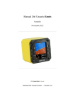
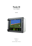
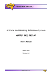
EMSIS-AHRS
September 2012
Stand Alone Version
EMSIS - AHRS
User’s manual for stand alone version
1 General description
The system consists of one 80 mm panel cut out compatible unit with colour graphic display and 6ix push buttons. The main
modules of the unit are:
-microcontroller
-sensor module (IAS and altitude)
-AHRS module with GPS receiver
1.1 Commands
On the front of the unit there are six push buttons and all commands should be executed using those
buttons.
QNH input command
after long press, pitch reset to zero
not active command, only active in setup
not active
escape only active in edit
mode selector*
* after short press the unit will change
from navigation page to setup and vice versa
1.1.1 Setup
Setup menu offers 6 items. To scroll use
buttons and to start edit use .
Menus are PW prevented and the password is
314.
Config
: don’t use by standalone variant
Sensors
: don’t use by standalone variant
Calibration : don’t use by standalone variant
Airspeed : input of colour arcs of IAS
Units
: input of local used units
Service
: see 4.1
2 Display description
Track information
AHRS
Altitude
IAS
QNH
1
EMSIS-AHRS
September 2012
Stand Alone Version
3 Connection of power and pressure
3.1 Power
EMSIS unit receives its power via power wires which are on the back side of the unit. Applied voltage
should not exceed 16V DC. There is no fuse inside the unit, so it is absolute obligatory to use external
fuse 2A.
3.2 Pneumatic connections
EMSIS – AHRS unit should be connected to aircraft static and total pressure sources. Both is necessary to ensure accurate air
speed and altitude indication and also function of AHRS. DAQU also needs MAP input.
3.3 GPS antenna
GPS information is necessary for accurate AHRS function, therefore a GPS antenna should be installed somewhere where
good GPS signal reception will be ensured.
3.4 BUS connectors
There are two bus systems used by NESIS- AHRS. 485 bus can be used to drive 57 mm (or 80 mm) indicators. Following
indicators can be connected to EMSIS AHRS 485 bus:
-IAS indicator
-altimeter
-variometer
3.5 OAT sensor
OAT sensor is a part of delivery and should be placed on a position where the temperature will match
outside air temperature as much as possible.
3.6 Connection diagram
Ptot
Pst
GPS
OAT
485
ENC
CAN
: total pressure (pitot)
: static pressure
: GPS antenna connection
: OAT sensor connection
: connection of indicators
: encoder connection*
: not occupied
*in case of using of external encoder
solution for QNH input use this plug
2
EMSIS-AHRS
September 2012
Stand Alone Version
4 Final check and adjustment
After installation works apply power to the system and provide functional check as follows:
-check OAT indication
-check altitude reading
-check IAS reading
-check QNH adjustment
4.1 AHRS adjustment
After installation final adjustment should be provided. Level the aircraft (roll and pitch) as for the cruise
flight and provide following procedure:
-switch to SERVICE menu of Setup
-input PW 2006
-a very typical message on the display will follow Calibrating please wait
-don’t move the aircraft during the procedure
-the process will finish automatically
-check position of the “aircraft” symbol if correct
5 Technical specifications and limits
-power input 12-16 V DC
-no fuse built into the system, use external fuse 2A
-power drain approximately: 200 mA
3