1
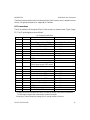
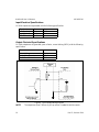
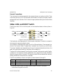
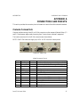
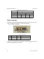
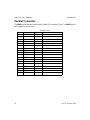
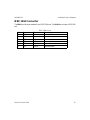
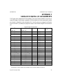
405-00017-00
VA40/VA41 User’s Reference
The analog camera interface also includes a serial port that is used to control camera functions
directly, like gain and exposure, for supported JAI cameras.
I/O Connections
The VA4x interfaces I/O through the 25-pin D-Sub connector on the back panel (Figure 2, page
12). The I/O pin designations are as follows:
I/O Connector Definitions
Pin #
1 & 25
2
3
4
5
6 & 19
7
8
9
10
11
Direction
–
In
In
In
In
–
Out
Out
Out
Out
–
12
13 & 14
15
16
17
18
20
21
22
23
24
Out
–
In
In
In
In
Out
Out
Out
Out
Out
iNspect/iLabel Definition
Ground
Sensor Trigger input or GPI0
Decision Trigger input or GPI2
Solution ID bit 1 or GPI4
Solution ID bit 3 or GPI6
Ground
Strobe output
Decision Output 1
GPO4
GPO6
not connected on standard NPN
(User Power input on PNP option)
Fused +12V at 0.7A
Ground
Change Solution input or GPI1
Solution ID bit 0 or GPI3
Solution ID bit 2 or GPI5
Solution ID bit 4 or GPI7
Decision Output 0
Inspection / Running Status
GPO5
GPO7
Fused +5 V at .75 A
Sherlock Definition
Channel 14 or Sensor Trigger
Channel 16 in
Channel 18 in
Channel 20 in
Channel 0 or Strobe output
Channel 2 out
Channel 4 out
Channel 6 out
Channel 15 in
Channel 17 in
Channel 19 in
channel 21 in
Channel 1 out
Channel 3 out
Channel 5 out
Channel 7 out
The application software (iNspect and iLabel) overrides I/O settings in the Camera Configuration
File, defining the trigger inputs, strobe output, and decision outputs.
Connecting a Firewire camera may reassign the I/O channel numbers in Sherlock.
Rev 07; 10 March 2010
15