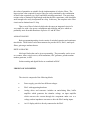
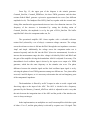
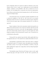
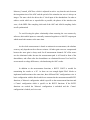
1
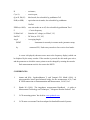
R
:
resistance,
C (or L)
:
reactive part,
Q (or D, Phi, Z) :
PAR (or SER)
third result, also selectable by pushbutton '3rd'
: equivalent circuit mode, also selectable by pushbutton
'Ser/Par'
ZERO (or ABS) :
zero trim mode on or off, also selectable by pushbutton 'Zero'
F
: Carrier frequency
U:500mVAC
:
Stimulus AC voltage (or 250mV, 1V)
ExtVDC
:
DC bias (or 2.5V, 0V)
Avg:8
:
Averaging length
REMT
:
Instrument is currently in remote mode (parameter setup
by
connected PC). Push rotary encoder to force exit to local mode.
A cursor is displayed (shown as arrow next to the frequency display) which can
be displaced by the rotary encoder. If the encoder is pressed, the edit mode gets active,
and the parameter to which the cursor points at can be changed by rotating the encoder.
Each measurement result is also sent to the RS232.
5. REFERENCES:
1.
Atman and M.A., Jagadeeshkumar V. and Vempati G.K. Muthi (1996), ‘A
microcontroller based quasi-balanced bridge for the measurement of L,C and
R’ IEEE transaction on Instrumentation and Measurement, Vol.45, No.3.
2.
Honda M. (1989), ‘The impedance measurement Handbook. A guide to
Measurement Technology and Techniques’, Yokogawa-Hewlett Packard Ltd.
3.
‘LCR measuring primer’ has dealt in www.quadtech.com.
4.
‘LCR meter user manual’ has been adapted in Stanford Research Systems.