1
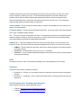
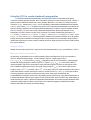
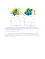
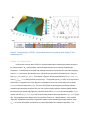
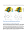
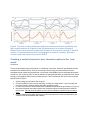
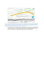
Figure 12. Two surface scenarios (C,F) for the design of the side channel along with planform (A,D)
and covariance plots (B,E) as discussed in the text.
In looking at the left scenario (e.g. Fig4C) note that the channel has cross stream asymmetry at the upstream bend
and then becomes broad and symmetric towards the middle of the straight section. Also, we can see the exit
doesn’t transition smoothly. To fix this we could simply adjust the point cloud in that area or, create contours and
manually smooth the transition. Or we can also adjust the shape of the channel by increasing the average width and
manipulating the width harmonics by creating a pinch at the curve, where the channel is constricted by tree islands,
and expansion below where the side channel corridor is wider. This is what was done for the right scenario, as
shown in Fig4F.
We make these types of changes by adjusting the waveform parameters of the bankfull width.
1. The left scenario uses the first sine and cosine term of the waveforms only. The amplitudes are 0.2 and 0.3
for the sine and cosine and both angular frequency values are set to 1, and the cosine term (second
waveform cell) phase shifted by “pi”. See the screenshot below.