1
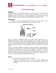
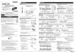
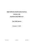
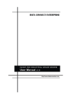
BeexyBox Type X
User Manual
© Beexy - Behavioral Experiment Software
Contents
1
2
3
4
Introduction
1
1.1
Rear Panel View . . . . . . . . . . . . . . . . . . . . . . . . . . . . . . . . . .
1
1.2
Accessories . . . . . . . . . . . . . . . . . . . . . . . . . . . . . . . . . . . . .
1
1.3
Handling
2
1.4
Additional Reading
. . . . . . . . . . . . . . . . . . . . . . . . . . . . . . . .
2
1.5
Support . . . . . . . . . . . . . . . . . . . . . . . . . . . . . . . . . . . . . . .
2
. . . . . . . . . . . . . . . . . . . . . . . . . . . . . . . . . . . . . .
Features
3
2.1
Digital Output Lines . . . . . . . . . . . . . . . . . . . . . . . . . . . . . . . .
3
2.2
Digital Input Lines . . . . . . . . . . . . . . . . . . . . . . . . . . . . . . . . .
3
2.3
Configurable Input/Output Lines . . . . . . . . . . . . . . . . . . . . . . . .
3
2.4
Analog Lines . . . . . . . . . . . . . . . . . . . . . . . . . . . . . . . . . . . .
3
2.5
Tone Generator . . . . . . . . . . . . . . . . . . . . . . . . . . . . . . . . . . .
3
2.6
Timers . . . . . . . . . . . . . . . . . . . . . . . . . . . . . . . . . . . . . . . .
3
2.7
Event Mask . . . . . . . . . . . . . . . . . . . . . . . . . . . . . . . . . . . . .
4
2.8
Input Mask . . . . . . . . . . . . . . . . . . . . . . . . . . . . . . . . . . . . .
4
2.9
Timing . . . . . . . . . . . . . . . . . . . . . . . . . . . . . . . . . . . . . . . .
4
2.10
HID Mode . . . . . . . . . . . . . . . . . . . . . . . . . . . . . . . . . . . . . .
4
2.11
Persistence Settings
5
. . . . . . . . . . . . . . . . . . . . . . . . . . . . . . .
Operating Modes
7
3.1
Off Mode And Standby Mode . . . . . . . . . . . . . . . . . . . . . . . . . . .
7
3.2
Input Test Mode . . . . . . . . . . . . . . . . . . . . . . . . . . . . . . . . . .
8
3.3
Voice-key Test Mode . . . . . . . . . . . . . . . . . . . . . . . . . . . . . . . .
8
3.4
HID Test Mode . . . . . . . . . . . . . . . . . . . . . . . . . . . . . . . . . . .
8
3.5
Serve Mode . . . . . . . . . . . . . . . . . . . . . . . . . . . . . . . . . . . . .
8
3.6
HID Mode . . . . . . . . . . . . . . . . . . . . . . . . . . . . . . . . . . . . . .
8
Connections
9
4.1
USB
. . . . . . . . . . . . . . . . . . . . . . . . . . . . . . . . . . . . . . . . .
9
4.2
RS-485 . . . . . . . . . . . . . . . . . . . . . . . . . . . . . . . . . . . . . . . .
9
4.3
Power . . . . . . . . . . . . . . . . . . . . . . . . . . . . . . . . . . . . . . . .
9
4.4
Digital Out . . . . . . . . . . . . . . . . . . . . . . . . . . . . . . . . . . . . .
10
4.5
Digital In
. . . . . . . . . . . . . . . . . . . . . . . . . . . . . . . . . . . . . .
10
4.6
Configurable In/Out . . . . . . . . . . . . . . . . . . . . . . . . . . . . . . . .
10
i
4.7
5
6
Analog In/Out . . . . . . . . . . . . . . . . . . . . . . . . . . . . . . . . . . . .
10
Jumper Settings
13
5.1
Jumper For Terminating RS-485 Communication Line . . . . . . . . . . . .
13
5.2
Jumper For Supply Voltage on Digital Out Connector . . . . . . . . . . . .
13
5.3
Jumper For Supply Voltage on Digital In Connector
. . . . . . . . . . . . .
13
5.4
Jumper For Supply Voltage on Configurable In/Out Connector . . . . . . .
14
Technical Specifications
15
ii
The information in this document may contain errors and is subject to change without notice.
Document version: 1
Please contact Beexy - Behavioral Experiment Software if you have any questions or
comments concerning this document.
Website:
http://www.beexy.nl
E-mail:
[email protected]
This work is licensed under a Creative Commons Attribution-NonCommercial-NoDerivatives
4.0 International License.
©2015 Beexy - Behavioral Experiment Software
iii
iv
1
Introduction
The BeexyBox Type X is a USB instrument box or input/output box. This device will for
example allow you to send out trigger signals to other devices, or to read sensors. It is
controlled from a host computer and shares its command set with the BeexyBox Type B
response box. Main features are:
• USB interface
• RS485 interface for controlling up to 31 slave devices
• 10 digital outputs (TTL-level)
• 10 digital inputs (TTL-level)
• 10 configurable input/output lines
• 2 analog DC inputs
• 2 analog AC inputs
• 1 analog AC output
• Sub-millisecond synchronization with host computer’s clock
The device requires an external power supply to operate (included).
1.1
Rear Panel View
On the rear panel (figure 1) there are 8 connectors/sockets. Their purpose are described
in detail in §4. The four connectors on the left-hand side are for communication and power
supply. The four connectors on the right-hand side provide the digital and analog IO lines.
RS−485
USB
Power
Digital Out
Digital In
Cfg In/Out
Analog In/Out
Figure 1: Rear panel
1.2
Accessories
Included accessories:
• USB-A to USB-B cable 1.8m (optionally 3m)
• Power supply 7.5V/800mA
• 2x IO cable 1.5m; 14-pin connector to pig tail (custom connector or additional cables
on request)
BeexyBox Type X User Manual
1 / 16
1.3
Handling
• The device is intended for controlling or monitoring other devices in a semi-permanent
non-industrial setup.
• If water or any other fluid is spilled on the device disconnect it immediately and consult
with Beexy support.
• Insert dust covers in unused IO connectors.
• Before inserting or removing the IO connectors drain off any static charge you may
have accumulated. This means touching a ground pad before handling the device.
• The device may only be opened to change or check jumpers as described in this manual. Unplug all connectors before opening the case. Make sure to discharge yourself
of static electricity.
1.4
Additional Reading
• BeexyBox Type B Timing Measurements1
• Bxymonitor User Manual
• BeexyBox Programming Manual
1.5
Support
If you have any questions about BeexyBox devices please contact Beexy - Behavioral
Experiment Software.
Website:
http://www.beexy.nl
E-mail:
[email protected]
1 With the exception of the measurements related to the RS-232 interface this document applies to the BeexyBox
Type X device as well.
2 / 16
BeexyBox Type X User Manual
2
Features
This section describes the features offered by the BeexyBox Type X.
2.1
Digital Output Lines
The device provides 10 digital output lines (5V, TTL-level). See connector marked “Digital
Out” in figure 1. See also §4.4. These output lines are buffered by a line-driver. Each line
has a 330Ω series resistor. This means each line can directly drive a LED. Current drawn
from each line should not exceed 8.5mA.
The output lines can be controlled by the experiment program. They can be manipulated
directly or by timer.
2.2
Digital Input Lines
The device provides 10 digital input lines (5V, TTL-level). See connector marked “Digital
In” in figure 1. See also §4.5. Each line has a 10kΩ pull-up resistor. This means if desired
a push-button can be directly connected between an input line and ground and the device
can be used as a response box.
2.3
Configurable Input/Output Lines
There are 10 configurable input/output lines (3.3V). See connector marked “Cfg In/Out” in
figure 1. See also §4.6. These lines are directly connected to the device’s microprocessor
unit. Each line can be configured as a digital input, a digital output or analog input.
Seven of these lines can be used for creating capacitive touch sensors.2 And four lines can
be used as PWM (pulse width modulation) outputs (which boils down to the lines becoming
analog outputs).3
2.4
Analog Lines
The device provides 2 analog DC inputs (2.5V), 2 analog AC inputs (2.5Vpeak-to-peak ) and 1
analog AC output (2.5Vpeak-to-peak ). The inputs have 16-bit (effectively 13-bit) resolution and
the output has 12-bit resolution. See connector marked “Analog In/Out” in figure 1. See
also §4.7.
As the analog output is AC coupled it only makes sense to use it for outputting (timed)
beeps using the tone generator function. Note, the analog output signal is available on the
connector as two separate outputs, but both lines carry the same signal.
The device does not perform voice-key function on its analog input(s).4
2.5
Tone Generator
The device contains a 10 voice tone generator. Each voice has frequency and waveform
type (square, sawtooth, triangle, sine, noise) attributes. The state (on or off) of each voice
can be controlled by the experiment program. They can be manipulated directly or by timer.
2.6
Timers
The device provides 10 interval timers. They serve no other purpose than to send a time
stamped message to the experiment program at predefined times. These timers can be
started/stopped by the experiment program.
2 Not
yet implemented in BeexyBox firmware 1.0.
yet implemented in BeexyBox firmware 1.0.
4 This feature is being considered for firmware V1.1 or later.
3 Not
BeexyBox Type X User Manual
3 / 16
2.7
Event Mask
To control which events are send to the experiment program running on the host computer
the device keeps an event mask. This mask can be set by the experiment program or by
using the bxymonitor utility. The following types of events can be enabled/disabled through
the event mask:
• input events
• timer events
• clock synchronize request events
2.8
Input Mask
By default all digital inputs found on the device are enabled. If it’s desired to (temporarily
or semi-permanently) disable one or more inputs you can do so by changing the device’s
input mask. This mask can be set by the experiment program or by using the bxymonitor
utility.
2.9
Timing
Timestamp resolution and precision of the clock in BeexyBox devices is 1μs. Sampling
frequency of the digital inputs and outputs is 24kHz5 (41.7μs).
Timing accuracy relative to the host computer’s clock depends on the ability to synchronize
the device’s clock with the host computer’s clock. We like the standard deviation of the
clock synchronization error to stay under 250μs / 3.
The most important factor affecting clock sync accuracy is the transmit latency from host
computer to device (downstream latency). The measurements presented in BeexyBox Type
B Timing Measurements (which applies to the BeexyBox Type X as well) show a latency (systematic error) for USB around 40μs under Linux (and ~80μs under Windows) with standard
deviation < 20μs. Once this systematic component has been measured it can be accounted
for.
The device’s clock and the host computer’s clock will not run at exactly the same pace and
both clocks speeds may vary due to temperature changes for example. This is clock drift.
The device corrects for any clock drift, provided the experiment program running on the
host computer regularly sends a sync-clock command to the device. See the BeexyBox
Type B Timing Measurements document or the BeexyBox Programming Manual to learn
more.
2.10
HID Mode
If desired the device can function as a HID (Human Interface Device). When used as a HID
keyboard, mouse or joystick the computer does not talk to the device; it just receives data
(key-press events etc.) from the device. These data have to be dealt with as appropriate
for keyboard, mouse or joystick input.
To associate a digital input action with a particular HID function (keyboard key, mouse button, mouse move, joystick button, etc.) you can use the bxymonitor utility. In HID mode the
default associations are: input 0 yields key ’0’, input 1 yields key ’1’, and so on.
5 Changing
4 / 16
the sampling rate to 20kHz or 25kHz is being considered.
BeexyBox Type X User Manual
2.11
Persistence Settings
The device has many settings that determine its behavior. The settings can be manipulated
and saved from your experiment program (or even a custom made program) or more easier,
by using the provided bxymonitor utility.
Bxymonitor is a command-line application for querying and manipulating settings as well
as for trying out and testing the device. The utility allows the user to type in commands for
the device to execute. The utility can also perform a number of timing measurements as
mentioned in §2.9.
BeexyBox Type X User Manual
5 / 16
6 / 16
BeexyBox Type X User Manual
3
Operating Modes
The operating modes are the same as for the BeexyBox Type B. However, not all modes are
valid or meaningful. The following operating modes are defined:
Off
Idle
Standby
Idle
Input Test
To test digital inputs, digital outputs and analog beep output
Voice-key Test
N.A. (this mode cannot be entered on the BeexyBox Type X)
HID Test
To test HID function
Serve
Device operates as response box
HID
Device operates as HID
Basically only modes Standby and Serve make sense, the other modes are implemented for
BeexyBox Type B compatibility. See BeexyBox Type B User Manual.
See also diagram in figure 2.
Input
Test
po
we
Voice−key
Test
ro
HID
Test
n
Standby
Off
Serve
HID
Figure 2: BeexyBox Type X operating modes
When the device is powered on it enters standby mode as can be seen in the diagram. The
dashed arrows in the diagram indicate paths that can only be taken programmatically, that
is from an experiment program or using the supplied bxymonitor utility.
Button-tapping to trigger a mode switch as for the BeexyBox Type B is not implemented
here.
Regardless of the operating mode the device always processes commands sent to it by the
host computer.
3.1
Off Mode And Standby Mode
In these modes the device is idle (waiting for a command to execute).
BeexyBox Type X User Manual
7 / 16
3.2
Input Test Mode
In the input test mode all inputs, outputs, and tone generator voices can be tested. While
pulling down an input a corresponding output should become high and a beep should be
played through the analog output. Each input plays a different tone.
3.3
Voice-key Test Mode
This mode is not implemented for the BeexyBox Type X.6
3.4
HID Test Mode
When in this mode the device converts button press/release actions to HID actions as defined using the bxymonitor utility. For instance, if input 0 maps to key ’a’ then pulling down
input 0 will cause the host computer notice that the ’a’ key has been typed.
3.5
Serve Mode
In this mode the device sends time stamped events to the experiment program as far as
enabled via the event mask (§2.7). Also all bells and whistles the device has to offer can be
utilized.
To enter this mode the experiment program must send the appropriate mode switch command to the device. At the end of the experiment the experiment program should preferably
place the device back to off mode or standby mode.
3.6
HID Mode
This mode is similar to the HID test mode. But in addition all bells and whistles the device
has to offer can be utilized. In contrast, in HID test mode only the ping and mode switch
commands are valid.
6 Voice-key
8 / 16
support is being considered for firmware V1.1 or later.
BeexyBox Type X User Manual
4
Connections
This section describes the rear panel connections of the BeexyBox Type X.
4.1
USB
A USB-B female connector is present for connecting the device via USB to the host computer.
All communication runs at 12 Mbit/s (AKA full speed). The device receives power via the USB
cable.
Some USB ports will yield poorer round-trip latencies then others. Try which ports (c.q.
driver) gives the best results. Using a USB hub or extender may also affect round-trip
latencies.
4.2
RS-485
A dual 8P8C connector also known as RJ45 connector is present for interconnecting RS-485
compatible devices. RS-485 is a standard that allows creating a multi-point communications
network with up to 32 units in a master-slave arrangement.
The two provide connectors are wired in parallel. This allows daisy-chaining devices (using
regular network cables) while the devices are actually connected in parallel as dictated by
RS-485.
The RJ45 pinout used is the taken from DMX512, a standard for digital communication networks that are commonly used to control stage lighting and effects.
Attention! Do NOT connect the device to a LAN socket. It will not work and may
cause harm to the device or to your network equipment.
The following figure shows how to connect master and slave devices. Both ends of the chain
must be terminated using a 120Ω resistor. For the BeexyBox Type X this is done by placing
a jumper (see §...).
Master (BeexyBox X)
RJ45
white−orange
D+
D−
GND
D+
D−
GND
1
orange
2
3
4
5
6
white−brown
7
brown
8
D+
D−
GND
Rt
D+
D−
NC
NC
NC
NC
GND
GND
Slave 1
Slave 2
Slave 3
Rt
Figure 3: Interconnecting BeexyBox Type X master and slave devices
4.3
Power
The power connector is a standard 2.1mm/5.5mm jack. Use a regulated power supply with
a voltage between 6.5V and 12V which can deliver at least 250mA. A 7.5V power supply is
recommended.
BeexyBox Type X User Manual
9 / 16
4.4
Digital Out
The pinout of the connector for the digital outputs is as drawn in figure 4. The connector is
a 14 pin DIN-41651 header which mates with the flat cable connector mentioned in §1.2.
0 2 4 6 8
Ground
5V
1 3 5 7 9
Figure 4: Digital out connector pinout
The signal level on the digital output lines is 5V (TTL level). Each line has a 330Ω series
resistor and can directly drive a standard LED. Current drawn should not exceed 8.5mA per
line.
4.5
Digital In
The pinout of the connector for the digital inputs is as drawn in figure 5. The connector is of
the same type as used for digital out (§4.4).
0 2 4 6 8
Ground
5V
1 3 5 7 9
Figure 5: Digital in connector pinout
The signal level for the digital input lines is 5V (TTL level). Each line has a 10kΩ pull-up
resistor.
4.6
Configurable In/Out
The pinout of the connector for the configurable input/output lines is as drawn in figure 6.
The connector is of the same type as used for digital out (§4.4).
0 2 4 6 8
Ground
3.3V
1 3 5 7 9
Figure 6: Configurable in/out connector pinout
The signal level for these lines is 3.3V. Note, these lines are directly connected to the device’s microprocessor unit, not buffered in any way. To avoid damage due to electrostatic
discharge make sure to drain of static charge you’ve accumulated before handling.
4.7
Analog In/Out
The pinout of the connector for the analog input/output lines is as drawn in figure 7. The
connector is of the same type as used for digital out (§4.4).
10 / 16
BeexyBox Type X User Manual
3.3V
Analog in 0 (DC)
Analog ground
Analog ground
Analog in 2 (AC)
Analog in 3 (AC)
Analog ground
Analog in 1 (DC)
3.3V
Analog out (AC)
Analog out (AC)
Analog ground
Figure 7: Analog in/out connector pinout
There are four groups of three pins each. The maximum signal level for these lines is 2.5V
for the DC lines and 2.5Vpeak-to-peak for the AC lines.
BeexyBox Type X User Manual
11 / 16
12 / 16
BeexyBox Type X User Manual
5
Jumper Settings
The BeexyBox Type X contains four jumpers indicated by the gray rectangles in figure 8.
When the jumper marked “TERM” is installed the RS-485 terminator resistor (see figure 3)
is in effect. The other three jumpers, from left to right, control feeding power to respectively
the digital out connector, the digital in connector and the configurable in/out connector.
Before opening the case make sure to drain off any static charge you may have collected
and unplug all connectors.
TERM
3V3
RS−485
5V
5V
DIGITAL OUT
DIGITAL IN
GP
ANALOG
Figure 8: Location of jumpers on circuit board
5.1
Jumper For Terminating RS-485 Communication Line
To enable/disable the RS-485 line termination place the “TERM” jumper as indicated in the
following table.
RS-485 terminator resistor jumper installed
disabled
no
enabled (factory default)
yes
5.2
Jumper For Supply Voltage on Digital Out Connector
To enable/disable feeding the 5V supply voltage to the digital out connector place the
jumper above the digital out connector as indicated in the following table.
5V on digital out connector jumper installed
disabled (factory default)
no
enabled
yes
5.3
Jumper For Supply Voltage on Digital In Connector
To enable/disable feeding the 5V supply voltage to the digital in connector place the jumper
above the digital in connector as indicated in the following table.
BeexyBox Type X User Manual
13 / 16
5V on digital in connector jumper installed
disabled (factory default)
no
enabled
yes
5.4
Jumper For Supply Voltage on Configurable In/Out Connector
To enable/disable feeding the 3.3V supply voltage to the configurable in/out connector place
the jumper above the configurable in/out connector as indicated in the following table.
3.3V on configurable in/out connector jumper installed
disabled (factory default)
no
enabled
yes
14 / 16
BeexyBox Type X User Manual
6
Technical Specifications
Case
• Flame retardant ABS gray plastic
• Dimensions:
– width 220mm
– depth 140mm
– height (excluding feet) 40mm
• Anti-slip rubber feet, height 1.5mm
Connectivity
See figure 1 from left to right:
• RS-485 interface: Baud-rate range 1200Bd..115200Bd; Connector dual RJ45; See also
§4.2
• USB interface: Fullspeed; Connector USB-B; See also §4.1
• External power: Range 6.5V..12V, recommended 7.5V; Connector 2.1mm/5.5mm jack;
See also §4.3
• Digital out: 10 lines, 5V (TTL-level); 330Ω series resistor; Connector 14 pin DIN-41651;
See also §4.4
• Digital in: 10 lines, 5V (TTL-level); 10kΩ pull-up resistor; Connector 14 pin DIN-41651;
See also §4.5
• Configurable in/out: 10 lines, 3.3V; Connector 14 pin DIN-41651; See also §4.6
• Analog in/out: 2 DC inputs 0..2.5V, 2 AC inputs 2.5Vpeak-to-peak , 1 AC output 2.5Vpeak-to-peak ;
Connector 14 pin DIN-41651; See also §4.7
Functions
• Digital input
• Digital output
• 16-bit (eff. 13-bit) analog sensor input
• 12-bit analog tone generator output
• Response box mode and or HID mode (can operate similar to BeexyBox Type B response box)
• 10 voice tone generator
• 10 timers
• Highly configurable, settings can be made persistent
Timing
• Timestamp resolution and precision: 1μs
• Inputs scanned at 24kHz
• In non-HID mode clock is synchronized with host computer’s clock; accuracy better
than 250μs, typically less than 50μs, See also BeexyBox Type B Timing Measurements
BeexyBox Type X User Manual
15 / 16
Power consumption
• 40mA..50mA (excluding connected loads)
Accessories
Included
• USB-A to USB-B cable 1.8m
• Power supply 7.5V/800mA
• 2x IO flat-cable 1.5m; 14-pin DIN 41651 flat-cable socket to pig tail (unfinished end
DIY; custom connector on request)
• Utility bxymonitor for setting and querying settings and for determining round-trip
latency, clock-drift and clock synchronization accuracy
Optional
• USB-A to USB-B cable 3m (instead of standard 1.8m)
• Additional IO flat-cable 1.5m; 14-pin DIN 41651 flat-cable socket to pig tail (unfinished
end DIY; custom connector on request)
16 / 16
BeexyBox Type X User Manual