1
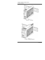
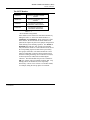
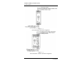
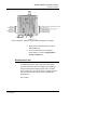
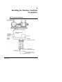
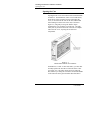
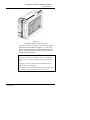
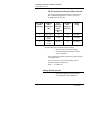
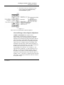
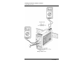
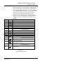
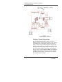
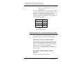
Machine Condition Transmitter™ (MCT) CMSS530(A) and CMSS590(A) SKF Condition Monitoring User Manual Part No. 31871000-EN Revision A User Manual Copyright 2002 by SKF Condition Monitoring, Inc. All rights reserved. 4141 Ruffin Road, San Diego, CA 92123-1841 USA Telephone: (858) 496-3400, Fax: (858) 496-3531 Customer Service: 1-800-523-7514 SKF Condition Monitoring Area Centers North and South America 4141 Ruffin Road San Diego, California 92123 USA Telephone (858) 496-3400 FAX (858) 496-3531 Asia, Pacific No. 1 Changi South Lane Level 2M Singapore 486070 Telephone 65-68767591 FAX 65-68767708 Visit us at our web site www.skfreliability.com SKF Condition Monitoring Service Policy, Warranty, Disclaimer, and Limitation of Remedies EXCEPT FOR THE LIMITED WARRANTY DESCRIBED BELOW, THERE ARE NO WARRANTIES, EXPRESSED OR IMPLIED, INCLUDING BUT NOT LIMITED TO THE IMPLIED WARRANTIES OF MERCHANTABILITY AND FITNESS FOR A PARTICULAR PURPOSE; ALL SUCH WARRANTIES ARE EXPRESSLY AND SPECIFICALLY DISCLAIMED. The MACHINE CONDITION TRANSMITTER is guaranteed free of defects in material and workmanship. Electronic components are guaranteed for a period of twelve (12) months, mechanical components, transducers, and cable assemblies are guaranteed for a period of ninety (90) days. The warranty period begins on the date the system is shipped from the SKF Condition Monitoring factory. This warranty does not extend to units that have been misused, altered, or repaired without manufacturer’s authorization. Defects or failures experienced during the warranty period will be corrected at no charge at the manufacturer’s facility. If, upon examination, it is found that the defect is not within the scope of this warranty, an estimate of repair charges and a request for authorization to proceed with repair will be submitted, along with a statement of the reasons the repairs are not considered to be covered by the warranty. This warranty does not extend to system components such as transducers, drivers, and cable assemblies manufactured by others. Warranty for these components will be their manufacturer’s standard. Manufacturer’s liability under this warranty is limited to repair or replacement of any defective instrument at the discretion of the manufacturer. In the event that any of the above limitations are held unenforceable, our liability to you shall not exceed the license fee you paid, regardless of the form of any claim. Because of the extreme diversity of ways that the product can be used, you are advised to test the product thoroughly for your purposes before relying on it. Contents Machine Condition Transmitter (MCT) The MCT Transmitter The MCT Monitor Identification Label Full Scale Range Powering the MCT Transducer Output User Manual Installing the Machine Condition Transmitter MCT Typical Installation Opening the Case Setting Monitor Alarms Interfacing the MCT with Other Monitoring Systems General Severity Level Guidelines Vibration measured in Velocity Vibration Enveloped Acceleration Measurements 1 1-1 1-3 1-4 1-6 1-12 1-15 1-17 1-19 2 2-1 2-2 2-4 2-10 A A-1 A-3 Index Machine Condition Transmitter (MCT) User Manual TOC - 1 1 Machine Condition Transmitter (MCT) SKF Reliability Systems’ Machine Condition Transmitter (MCT) modules are compact rail-mounted devices that convert part of a wide-band input signal to a signal proportional to machine vibration. The MCT Transmitter There are two MCT versions, CMSS530 is a 4-20 mA velocity transmitter, and CMSS590 is an enveloped acceleration transmitter. Each is factory configured for use with a low-impedance accelerometer. The velocity transmitter can also be configured for use with a lowimpedance velocity sensor, or electro-mechanical velocity sensor. The sensor input signal is processed to determine its overall vibration level in terms of either velocity (RMS or Peak) or enveloped acceleration. Output is a standard 420 mA current proportional to this level, within a specified full range such as 0-1 IPS RMS for velocity, or 0-10 gE for enveloped acceleration. The 4-20 mA output is suitable for a direct connection to a Programmable Logic Controller (PLC) or Distributed Control System (DCS). A BNC connector on the front of the unit provides access to the buffered transducer signal for use with portable monitoring equipment, such as the SKF Reliability Systems’ MicrologTM. Mechanical Condition Transmitter (MCT) User Manual 1-1 Machine Condition Transmitter (MCT) The MCT Transmitter Figure 1 - 1. The MCT – Transmitter. Figure 1 - 2. The MCT – Transmitter/Monitor. 1-2 Machine Condition Transmitter (MCT) User Manual Machine Condition Transmitter (MCT) The MCT Monitor The MCT Monitor CMSS530- Velocity Transmitter without Monitor CMSS530A Velocity Transmitter with Monitor CMSS590- Enveloped Acceleration Transmitter without Monitor CMSS90A Enveloped Acceleration Transmitter with Monitor Table 1 - 1. MCT Module Configurations. MCT modules can be ordered as stand alone Monitors by adding the suffix "A" to the basic model number (i.e., CMSS530A and CMSS590A). When ordered as a stand alone monitor, the unit includes an alarm module front panel and an output relay that can be jumper configured for either latching or non-latching operation. The ALERT or DANGER LED will turn "ON" and the corresponding relay will actuate whenever overall vibration levels exceed the corresponding setpoint for more than a preset delay time (jumper selectable). The alarm module has a front panel accessible BNC connector and associated selector switch for reading the analog current vibration level (CV) or alarm setpoints (A or D) with a standard digital voltmeter. The alarm module also provides a transducer OK relay contact, and a trip multiply function (Tx). Trip multiply allows the alarm levels to be temporarily increased by a factor of two or three to avoid false alarms, for example, during the start-up phase of a machine. Machine Condition Transmitter (MCT) User Manual 1-3 Machine Condition Transmitter (MCT) The MCT Monitor Figure 1 - 3. MCT Transmitter General Pin Assignment. Figure 1 - 4. MCT Transmitter / Monitor General Pin Assignment. 1-4 Machine Condition Transmitter (MCT) User Manual Machine Condition Transmitter (MCT) Identification Label Figure 1 - 5. MCT Transmitter / Monitor Top and Bottom Pluggable Terminals. Both monitors and transmitters mount on standard DIN rail. For more information concerning the alarm settings, reference Setting Monitor Alarms in Chapter 2. Identification Label An identification label on the right side of the module provides information about the module type including a unique model number identifying data of the module’s basic configuration, such as the factory configured sensor type, the measurement method and the installed filter characteristics. For example: Machine Condition Transmitter (MCT) User Manual 1-5 Machine Condition Transmitter (MCT) Identification Label Standard Units Each enveloped acceleration transmitter provides three band-pass filters. Reference Table 2-1 for details. 1-6 Machine Condition Transmitter (MCT) User Manual Machine Condition Transmitter (MCT) Full Scale Range Special Units The unique serial number identifies individual transmitters and is used for warranty, quality control, and service purposes. The label also has the CSA and CE approval marks. Full Scale Range Preset Options The MCT comes factory with the most common full scale range. Other ranges may be implemented by installing jumpers as shown in Tables 1-2 and 1-3. See Opening the Case in Chapter 2 for information on gaining access to jumpers. Changing ranges by jumper selection only will introduce an additional error of .5% typical, 2% max. For greater accuracy, the system range must be re-calibrated. Machine Condition Transmitter (MCT) User Manual 1-7 Machine Condition Transmitter (MCT) Full Scale Range Full Scale: Range: English Metric Jumper 01 .5 IPS 12.5 mm/sec E2 02* 1.0 IPS 25 mm/sec E3 03 1.5 IPS 37.5 mm/sec E2 and E3 04 2.0 IPS 50 mm/sec E3 and E4 05 2.5 IPS 62.5 mm/sec E2 and E3 and E4 Table 1 - 2. MCT VEL. Full scale option for all velocity transmitter units is factory preset to 02, for 0 to 1.0 IPS or to 25.0 mm/sec if not otherwise specified in the model number. Range: Full Scale: Jumper 01* 10 gE E8 02 30 gE E9 03 80 gE E10 Table 1 - 3. MCT ENV. Full scale option for all enveloped acceleration transmitter units is factory preset to 10 gE. The Filter option is set to Filter 3 (500 Hz to 10 Hz), unless otherwise specified in the model number. In the tables above, * indicates the factory preset range. 1-8 Machine Condition Transmitter (MCT) User Manual Machine Condition Transmitter (MCT) Full Scale Range Jumper Locations Setting Jumper Configuration E2 E3 E4 Range Settings E2 0 to 0.5 IPS or 12.5 mm/sec Option: 01 E2 E3 E4 E3 0 to 1.0 IPS or 25.0 mm/sec /*factory preset Option: 02 E2 E3 E4 E2 and E3 0 to 1.5 IPS or 37.5 mm/sec Option: 03 E2 E3 E4 E3 and E4 0 to 2.0 IPS or 50.0 mm/sec Option: 04 E2 E3 E4 E1 E5 E3 and E4 and E5 0 to 2.5 IPS or 62.5 mm/sec Option: 05 Special Filters Remove to install Filter 1 Remove to install Filter 2 Table 1 - 4. MCT Velocity Options. Machine Condition Transmitter (MCT) User Manual 1-9 Machine Condition Transmitter (MCT) Full Scale Range Figure 1 - 6. MCT Velocity Peak Detection Jumper Locations. 1 - 10 Machine Condition Transmitter (MCT) User Manual Machine Condition Transmitter (MCT) Full Scale Range Figure 1 - 7. MCT Velocity RMS Detection Jumper Locations. Machine Condition Transmitter (MCT) User Manual 1 - 11 Machine Condition Transmitter (MCT) Full Scale Range Setting E1* E2 E5 E3* E6* E4 E7 E8* E9 E10 Jumper Configuration Constant Current Source Provides constant current / *factory preset No current supply, uses buffered output as signal input Selectable Filterbands ENV Filter #4 (5 kHz to 40 kHz) ENV Filter #3 (500 Hz to 10 kHz)/ *factory preset *factory preset ENV Filter #2 (50 Hz to 1.0 kHz) Range Settings Range 1 (0 to 10 gE) / Range 2 (0 to 30 gE) Range 3 (0 to 80 gE) *factory preset Table 1 - 5. MCT Enveloped Acceleration Options. 1 - 12 Machine Condition Transmitter (MCT) User Manual Machine Condition Transmitter (MCT) Powering the MCT Figure 1 - 8. MCT Enveloped Acceleration Jumper Locations. Powering the MCT The MCT requires externally supplied dc power. The selected power supply should have a nominal output of +24 Vdc and be capable of supplying minimum currents noted in Table 1-4: Machine Condition Transmitter (MCT) User Manual 1 - 13 Machine Condition Transmitter (MCT) Powering the MCT Model Number Minimum Power Supply/Unit CMSS530- 55 mA CMSS530A 110 mA CMSS590- 75 mA CMSS590A 125 mA Table 1 - 6. MCT Minimum Currents. A regulated power supply dedicated to the vibration monitoring system is recommended. It is also recommended that connections between the power-supply and the transmitter/monitors be made with shielded twisted instrument cable. The cable shield should float at the transmitter/monitor, and connect to ground at the power supply / system common end only. The MCT regulates dc power internally to prevent a fault on the output of one channel from affecting other channels. When power is first applied to a transmitter/monitor after connecting the transducer, a delay of approximately 30 seconds will occur before the OK LED turns "ON". Power Supply Distribution If more than one MCT module is installed, terminal blocks for power and ground must be used. From these terminal blocks, 24 Vdc power is distributed to each individual module. It is recommended to use individual fuse terminals for each positive supply line so a power failure in a single MCT module will not affect the other modules. 1 - 14 Machine Condition Transmitter (MCT) User Manual Machine Condition Transmitter (MCT) Powering the MCT Figure 1 - 9. Typical Power Wiring Configuration. Machine Condition Transmitter (MCT) User Manual 1 - 15 Machine Condition Transmitter (MCT) Transducer Grounding When experiencing interference on the output signals due to common ground connections, it is recommended to connect the +24 V GND at the power distribution terminals to the protective ground (PE). For CE-approved systems, it is recommended to use shielded twisted pair cables for all signal connections. Except for the sensor signal (for example, accelerometer), all shields must be connected to PE. Transducer The velocity transmitter unit is factory configured for use with one of three transducer types. The specific type is identified by four digits (for example, 100A) immediately following the basic model number on the side label. This number is the transducer sensitivity in either mV/g or mV/IPS (see Table 1-5 below). Type I.D. Transducer Type Sensitivity 100A low-impedance, constant current powered accelerometer mV/g 100V low-impedance, constant current powered velocity sensor mV/IPS 500E self-generating, electro-mechanical velocity sensor mV/IPS Table 1 - 7. Identifying Transducer Type and Sensitivity. For example: 100A indicates the transducer is a 100 mV/g low-impedance accelerometer. Other sensitivities are available by special order. 1 - 16 Machine Condition Transmitter (MCT) User Manual Machine Condition Transmitter (MCT) Transducer The enveloped acceleration transmitter unit always uses a 100 mV/g low-impedance, constant current powered accelerometer. Transducer Cable The MCT provides power for the transducer via a nominal 4.4 mA constant current source. This is generally enough current to allow operation with transducer cables extending up to about 100 ft. Longer cables may be used, depending on the sensor and cable specifications. However, it is strongly recommended that the transmitter/monitor be mounted as close as practical to the associated transducer. This will prevent signal distortion associated with current drive limitations, and will minimize interference from external electro-magnetic noise sources (EMI). A well shielded, properly installed transducer cable is necessary to obtain reliable operation. Shielded twisted pair cables designed and pre-fitted with the proper transducer connector or sensors with integral cable, which are sold for this specific purpose, are recommended. The cable shield should be open at the transmitter end and connected to ground through the sensor casing. Alternatively, the cable shield could be open at the transmitter end, and connected to common xdcr- terminal at the transmitter/monitor input only. Transducer OK Circuit The MCT incorporates a transducer OK circuit. This feature continuously monitors the transducer bias and signal voltage. If this voltage exceeds preset limits, the 420 mA output current is reduced to less than 2 mA (typically 0 mA) to allow detection of the fault condition at the associated PLC or DCS system. A green OK LED on the front of the unit (normally "ON" in an OK condition) turns "OFF" to provide a local indication of the fault condition. For low-impedance, constant current powered transducers, this circuit will effectively detect open, shorted, or reversed transducer connections. When a Machine Condition Transmitter (MCT) User Manual 1 - 17 Machine Condition Transmitter (MCT) Output detected fault is remedied, a delay of approximately 30 seconds occurs before the unit returns to the OK condition and the OK LED turns back "ON". A detected fault will also disable the ALERT and DANGER alarms / relays until the fault is removed and an OK condition exists. When configured for use with an electromechanical transducer (E), the OK circuit will only detect an open circuit condition of the transducer / cable. Output 4-20 mA Output The primary output of the transmitter/monitor is the 4-20 mA current output, which is scaled proportional to the full scale range of the unit. For example, if the range is 0 - 1 IPS peak, then 4 mA indicates a reading of 0.00 IPS, and 20 mA indicates a reading of 1.00 IPS peak. This output is intended to drive a maximum resistive load of 500 Ohms with respect to system common at the PLC / DCS input. A precision 0.25 watt, 250 Ohm resistor is the recommended load. This will convert the 4-20 mA current reading to a 1 to 5 Vdc reading for the PLC / DCS. For example, if the range is 0 to 0.5 IPS, then 1 Vdc indicates a reading of 0 IPS, and 5 Vdc indicates a reading of 0.5 IPS. A short to ground (common) on this output will not cause damage. The relationship of the measured vibration parameter to the output current is displayed in the following equation: Units of Vibration = Measured Current - 4 mA × Full Scale Value 16 mA Example Measured Current = 12 mA; Full Scale = 1 IPS Converted Output Reading = 1 - 18 12 mA - 4mA × 1 IPS = 0.5 IPS 16 mA Machine Condition Transmitter (MCT) User Manual Machine Condition Transmitter (MCT) Output The relationship of the measured vibration parameter to the output voltage, when using a 250 Ohm resistor, is displayed in the following equation: Units of Vibration = FullScaleValue × (Measured Voltage − 1) 4V Example: Measured Voltage = 3V; Full Scale 0.5 IPS Converted Output Reading = 0.5 IPS × (3V − 1) = 0.25 IPS 4V Buffered Output The MCT provides access to the buffered transducer signal using a BNC connector on the front of the unit and on a screw terminal at the top of the unit. These buffered outputs have the same sensitivities, units, and bias voltages as the transducer itself (i.e., mV/g for an accelerometer or mV/IPS for a velocity transducer). This output can be connected to portable monitoring equipment or analyzers (i.e., SKF Reliability Systems’ MicrologTM), or can be used to check the bias output voltage (BOV) of low-impedance transducers using a digital voltmeter. The buffered output is unfiltered. For electro-mechanical velocity transducers only: The buffered output sensitivity is scaled to 100 mV/IPS, regardless of the actual input sensitivity. For example, a 145 mV/IPS transducer will have a scaled buffered output sensitivity of 100 mV/IPS. Machine Condition Transmitter (MCT) User Manual 1 - 19 Machine Condition Transmitter (MCT) User Manual User Manual 1 - 20 Machine Condition Transmitter (MCT) User Manual 2 Installing the Machine Condition Transmitter MCT Typical Installation Machine Condition Transmitter (MCT) User Manual 2-1 Installing the Machine Condition Transmitter Opening the Case Opening the Case Opening the MCT case is best done with a small flat-blade screwdriver. On transmitters (1inch / 26 mm wide units), insert the tip of the screwdriver between the right side cover (as viewed from the front of the unit) and the DIN rail mounting foot at the back of the unit, as shown in Figure 2-1, and gently leverage the blade to begin separating the cover from the rest of the unit. Carefully work your way around to the front of the unit to complete removal of the cover, exposing the circuit board components. Figure 2 - 1. Blade Insertion Point on Transmitter. On Monitors (1.6 inch / 41 mm wide units), you must first carefully separate the two halves of the unit at the center (see Figure 2-2). The sides do not need to be removed. This is done by working the screwdriver around the middle of the unit in the same general manner described above. 2-2 Machine Condition Transmitter (MCT) User Manual Installing the Machine Condition Transmitter Opening the Case Figure 2 - 2. Transmitter/Monitor Separated at Center. As the two sides start to separate, you will see that a short ribbon cable inside holds them together. To remove this cable, carefully pull it away from the left hand side of the unit (as viewed from the front). The cable stays with the right hand side permanently. Important - When reinstalling this cable, make sure it is properly connected to the mating connector, and that the bend in the cable goes towards the front panel side of the unit. If the unit is closed with the bend towards the back, the ribbon cable can be damaged. Also, make sure the ribbon cable connector does not catch on the relays when pressing the unit back together. Mechanical Condition Transmitter (MCT) User Manual 2-3 Installing the Machine Condition Transmitter Setting Monitor Alarms MCT Enveloped Acceleration Filter Selection The enveloped acceleration transmitter is delivered with three standard band-pass filters. Table 2-1 shows the available filters for each unit. Filter Band Number (Microlog) BandPass Filter Frequencies (Hz) Fmax Setting for Microlog When Compared( Hz) Old MCM Filter Range for Reference Jumper Setting 2 50 to 1,000 100 -44 E4 and E7 3 500 to 10,000 1,000 -66 E3 and E6 4 5,000 to 40,000 10,000 -88 E2 and E5 Table 2 - 1. Integrated Enveloped Acceleration Filter Settings. The factory preset for the enveloped acceleration transmitter module is Filter 3 (500 to 10,000Hz). Use the following guideline to define the proper band-pass for the application. The low frequency roll-off of the band-pass filter to eliminate rotational components is: Fmin > = 10 x RPM / 60 Setting Monitor Alarms This section applies only to the Monitor units (CMSS530A and CMSS590A). 2-4 Machine Condition Transmitter (MCT) User Manual Installing the Machine Condition Transmitter Setting Monitor Alarms For a brief overview of vibration severity levels, reference the General Severity Level Guidelines appendix. Figure 2 - 3. MCT Front View With Monitor Options Explained. Alert and Danger Alarm Setpoint Adjustment ALERT and DANGER alarm setpoints can be independently set in the field by turning the front panel selector switch to the associated position (A or D) and adjusting the associated front panel potentiometer until the correct dc voltage is measured at BNC connector located directly above the selector switch. Adjusting the setpoint requires the use of a digital voltmeter, knowledge of the transmitter's full scale range, and the desired setpoint as a percentage of the full scale range. The voltage measured at the BNC will vary between 0 Vdc and 5 Vdc, corresponding to 0 to full scale. For example, 2.5 Vdc represents 50% of full scale, 3.75 Vdc represents 75% of full scale. To calculate the required setpoint voltage, use the equation, 5(.xx) where .xx is the desired percentage expressed as a decimal fraction of the full scale range. For example, 5(.60) = 3.00 Vdc for a setpoint of 60% of the full scale range. Turning the potentiometer clockwise increases the setpoint voltage. Mechanical Condition Transmitter (MCT) User Manual 2-5 Installing the Machine Condition Transmitter Setting Monitor Alarms Figure 2 - 4. Setting Alarm Levels. 2-6 Machine Condition Transmitter (MCT) User Manual Installing the Machine Condition Transmitter Setting Monitor Alarms Alert and Danger Alarm Delays Adjustment Setting Jumper The Alert and Danger alarm delays can be independently set by internal jumper selection to .1, 1, 3, 6, or 10 seconds. The purpose of the delay is to reduce nuisance alarms caused by external electrical noise and/or transient vibration events. Both the Alert and Danger delays are factory set to the 3-second position. To change the delay, open the unit and move the delay jumpers to the proper position. Configuration Alert Time Delay E1 E2 E3* E4 E5 0.1 sec 1 sec 3 sec / 6 sec 10 sec E6 E7 E8* E9 E10 0.1 sec 1 sec 3 sec / 6 sec 10 sec *factory preset Danger Time Delay E11* E12* E13* *factory preset Latching / Non-latching Alarms Open: Alert Non-latching / *factory preset Closed: Alert Latching Open: Danger Non-latching / *factory preset Closed: Danger Latching Open: factor 2x Closed: factor 3x Trip Multiply factor /*factory preset Table 2 - 2. Monitor Jumper Options. Mechanical Condition Transmitter (MCT) User Manual 2-7 Installing the Machine Condition Transmitter Setting Monitor Alarms Figure 2 - 5. Monitor Jumper Locations. Latching / Non-latching Alarms The Alert and Danger alarms are factory set for nonlatching operation. This means that whenever the vibration level drops below the associated setpoint for more than about 1 second, the associated relay will de-energize and the alarm LED will turn off. The alarms can also be set for latching operation by installing shunts on jumpers E1 and E2 on the Alarm module circuit board. Latched alarms may be reset by closing the RESET (RST) and COMMON (COM) contacts at the top of the unit. This may be done with an external switch, dry contact relay, or by shorting the terminals together by hand. 2-8 Machine Condition Transmitter (MCT) User Manual Installing the Machine Condition Transmitter Setting Monitor Alarms Important - Do not apply voltage to either the RST or COM terminals. If several monitors are mounted together, the RST terminals may be daisy-chained together and switched to COM (system common) as a group. Trip Multiply The alarm module provides a trip multiply feature. This feature allows the user to temporarily double (standard) or triple (jumper selectable) the normal setpoints during periods of normal high vibration, such as start-ups. To actuate the trip multiply feature, the Tx terminal at the top of the alarm module must be closed to the adjacent COM terminal. This may be done with an external switch, dry contact relay, or by shorting the terminals together by hand. Important - Do not apply voltage to either the Tx or COM terminals. If several monitors are mounted together, the Tx terminals may be daisy-chained together and switched to COM (system common) as a group. Alarm Relays The ALERT, DANGER and OK relays are independent, single-pole-double throw relays. NO, ARM, and NC contacts are available through a plugable screw connector at the bottom of the monitor. OK relay contacts are available on fixed screw terminals at the bottom front of the alarm module. Relay contacts are rated 5 Amps at 30 Vdc or 125 Vac, resistive load. This rating includes any inrush current the load draws. For loads that are not purely resistive, the contact switching capability needs to be considered carefully in terms of this inrush current and rated accordingly. Mechanical Condition Transmitter (MCT) User Manual 2-9 Installing the Machine Condition Transmitter Interfacing the MCT with Other Monitoring Systems The user is reminded to take care when applying relays. The factory intended purpose of providing relay contacts is to operate relatively low power alarm annunciators, act as a dry or low dc voltage contact closure input to other systems, or act to actuate an appropriately sized slave relay for larger loads such as shutting down a motor. Relays are socketed and can be replaced. Rated Amps Voltage 5A 30 Vdc 5A 125 Vac 2.5A 250 Vac Table 2 - 3. Relay Contacts Rating. Interfacing the MCT with Other Monitoring Systems The MCT CMSS530 and CMSS590 modules interface with equipment used for process control and data analysis. Interfacing to Process Control Systems Interface options for process control systems are the static output 4-20 mA dc and the low power change-over relay contacts. The maximum load resistance of all connected instruments in the current loop is 500 Ohms. Reference the section 4-20 mA Output in Chapter 1 for more information. Interfacing to SKF Reliability Systems Products Consider the following interface options: 2 - 10 Machine Condition Transmitter (MCT) User Manual Installing the Machine Condition Transmitter Interfacing the MCT with Other Monitoring Systems • Use SKF Reliability Systems equipment to analyze MCT module readings. • Use MCT modules as a front end to on-line condition monitoring equipment. Figure 2-6 shows a combination of the above mentioned interface options. Figure 2 - 6. MCT CMSS530/590 Interfacing. Analyzing MCT Readings Unlike other SKF Reliability Systems’ analyzing products that use digital signal processing (i.e., Microlog, Multilog Mechanical Condition Transmitter (MCT) User Manual 2 - 11 Installing the Machine Condition Transmitter Interfacing the MCT with Other Monitoring Systems CMMA320 and Monitor Interface Module (MIM) CMMA162), MCT modules use analog signal processing techniques, so be careful when comparing results with digital instruments. For enveloped acceleration (gE) applications, the filter ranges in the Microlog and Multilog are equal, but the filter range of the enveloper circuitry in the Vib Pen Plus is fixed between 5 kHz and 10 kHz to obtain a general bandwidth where low frequency influences, due to hand held operation, are eliminated. Detection methods of the Microlog and Multilog are, in general, based upon detecting a maximum and minimum peak value within the whole time period of the measurement. From this peak-to-peak value, the zero peak value is calculated. The RMS value is always derived from the calculated spectrum and is not a true RMS conversion on the dynamic time signal (unlike the MCT modules). Furthermore, MCT modules use averaging methods to prevent unwanted fluctuations. The number of averages for the Multilog and Microlog are free selectable. It is advised to select 4 to 8 averages to create a comparable total measurement time period. Guidelines for using the Microlog as an analysis instrument in combination with the MCT modules are provided: Peak-to-Peak Measurements with the Microlog (Acceleration and Enveloped Acceleration) The buffered vibration output is used as an input signal to the Microlog. The selected enveloped acceleration filter setting for the Microlog must be equal to the filter choice on the enveloped acceleration transmitter. The maximum frequency must be set at twice the value of the selected low corner cut off frequency of the enveloped acceleration filter (for example, filter 500 Hz to 10 kHz results in a maximum analyzing frequency of 1 kHz). Peak to Peak readings on the Microlog can be compared to the Peak reading of the MCT module. This difference of detection method is based upon the fact that the Microlog 2 - 12 Machine Condition Transmitter (MCT) User Manual Installing the Machine Condition Transmitter Interfacing the MCT with Other Monitoring Systems has an AC coupled signal processing path, while the MCT modules use a dc coupling. RMS Measurements with the Microlog (Acceleration and Velocity) The buffered vibration output is used as an input to the Microlog. The Microlog’s frequency settings must be equal to the filter bandwidth settings of the (Velocity) MCT CMSS530 module. The detection method must be set to RMS. Important - The MCT VEL module uses an analog filter and integrator which measure continuously. The Multilog and Microlog calculate the RMS value from the spectrum, which is not continuously processed. This discontinuity, which is minimized by selecting the Hanning window, may cause low frequency problems which result in ski-slopes after integration. These possible ski-slope effects may have large influences on the RMS overall velocity reading. Peak Detection in Velocity The MCT velocity modules with peak detection provide a true peak reading, in contrary to the older MCM modules, which provided a "pseudo" peak, derived from the RMS reading. True peak detection typically results in higher values when data is collected at the same measurement location over the same frequency range. The data can be trended and analyzed, nonetheless. If the user is more familiar with the Calculated Peak (RMS x 1.414), specify the RMS detection when ordering. Select an approximate 1.4 times higher full scale value to get the same results. For example, the older MCM has a full scale of 1 IPS and peak (pseudo) detection. An MCT velocity module with a full scale of 1.5 IPS and RMS detection will deliver the same results. Mechanical Condition Transmitter (MCT) User Manual 2 - 13 Installing the Machine Condition Transmitter User Notes User Notes 2 - 14 Machine Condition Transmitter (MCT) User Manual Appendix General Severity Level Guidelines When considering severity levels, be aware that standards can only provide general guidelines to determine initial alarm settings. Such guidelines should never substitute experience and good judgement. The most reliable method of determining alarm settings is to trend vibration readings over time, establish baseline values and alarm settings above baseline values. Vibration measured in Velocity For vibration velocity, ISO standards, such as ISO 10816, First Edition 1995, or VDI 2056 guidelines, are generally accepted. ISO 10816 with the title ‘Mechanical vibration – Evaluation of machine vibration by measurements on nonrotating parts’ consists of six parts. Part 1 (10816-1) determines general guidelines and is followed by the additional parts of ISO 10816, for example Part 2 (108162) for land-based steam turbines and generators in excess of 50 MW with normal operating speeds of 1500 RPM, 1800 RPM, 3000 RPM and 3600 RPM. The following severity chart is in accordance with the ISO 10816-2 guidelines. For exceptions to this guideline and for more information, reference the ISO 10816-2 document. Machine Condition Transmitter (MCT) User Manual A-1 General Severity Level Guidelines Vibration measured in Velocity ISO 10816-2 Speed (RPM) Velocity mm/sec RMS Steam Turbines and Generators 1500 or 1800 3000 or 3600 Damage occurs 11.8 10.0 8.5 7.5 Restricted Operation Unrestricted Operation 5.3 3.8 2.8 1.4 0.0 Newly Commissioned Machinery Table A - 1. Vibration Severity Chart ISO 10816-2. Industrial machines with nominal power above 15 kW and nominal speeds between 120 RPM and 15000 RPM when measured in position are covered by ISO 10816-3. The machines are separated into 4 different groups: Group 1: Large machinery and electrical machines with shaft height greater than 315 mm that are normally equipped with sleeve bearings. Group 2: Medium-size machines and electrical machines with shaft height between 160 mm and 315 mm that are normally equipped with rolling element bearings and operate at speeds above 600 RPM. Group 3: Pumps with multivane impellers and separate drivers with rated power above 15 kW. Machines of this A-2 Machine Condition Transmitter (MCT) User Manual General Severity Level Guidelines Vibration Enveloped Acceleration Measurements group may be equipped with sleeve or rolling element bearings. Group 4: Pumps with multivane impellers and with integrated drivers that are equipped with sleeve or rolling element bearings. ISO 10816-3 Rated Power Machinery Group 2&4 15 kW – 300 kW Machinery Group 1&3 Group 1: 300 kW – 50 MW Group 3: above 15 kW Velocity mm/sec RMS Damage 11.0 7.1 4.5 3.5 2.8 2.3 1.4 0.7 0.0 Foundation occurs Restricted Operation Unrestricted Operation Newly Rigid Commissioned Flexible Rigid Table A - 2. Vibration Severity Chart ISO 10816-3. Machinery Flexible Vibration Enveloped Acceleration Measurements Severity levels for machine vibration and bearing defect detection by means of the enveloping technique are needed to classify the machine condition according to standards and practical guidelines. For enveloped acceleration in all forms, severity levels are related to speed and bearing size. The bearing size is generally related to the load capabilities of the machine. Mechanical Condition Transmitter (MCT) User Manual A-3 General Severity Level Guidelines Vibration Enveloped Acceleration Measurements The higher the speed, the higher the energy generated by impacts as elements roll over bearing damage. The relation: Maximum shaft speed times shaft diameter has a maximum, depending on the bearing technology. Notice that for bigger bearings the speed is limited, and therefore, the severity levels are also limited. Carefully select the severity levels for enveloped acceleration using machine knowledge. Sensor location and sensor installation is important for successful machine monitoring. The boundaries between different states of severity conditions are less defined. Comparative and relative judgement methods are preferred above absolute judgement and the application of standards. For creating a comparative measurement, the process control system is able to create a trend of the vibration signal. This signal can be compared against a ‘baseline’ overall measurement of that measurement point, with the knowledge that the machine is running under normal conditions. In many cases, periodic measurements have been performed on equipment before a permanent monitor (such as the MCT system) is installed. The knowledge of those measurements and the machine behavior provides a good indication of effective alarm level settings. A-4 Machine Condition Transmitter (MCT) User Manual General Severity Level Guidelines Vibration Enveloped Acceleration Measurements Danger Setting (gE) To be used with CMSS793, 797 accelerometers CMVA55, CMVA320, filter 3, fmax=30,000 CPM, pk-pk reading. 3600 3000 1800 1500 RPM 1200 900 600 400 10 3.30 200 1 100 0.33 Alert Setting (gE) (Scale is 1/3 of Danger Scale) 33.3 100 0.03 0.1 10 100 1000 Shaft Diameter (mm) Figure A - 1. Enveloped Acceleration Alarm Guidelines (Fmax = 60,000 CPM). To utilize the above chart, the following parameters must be known: • Bearing bore diameter in mm (indicates load) • Shaft speed in RPM Assumptions for using the above chart are necessary as deviations from standardized data collection greatly affect enveloped acceleration readings. Assumptions are as follows: • Filter 3 = 500-10,000 Hz • Fmax = 60,000 CPM / 1,000 Hz A scaling factor is required for other Fmax values. A scaling equation is provided in Part II. • Sensor = CMSS793 or CMSS797 or MCD probe • Detection = Peak to Peak Mechanical Condition Transmitter (MCT) User Manual A-5 General Severity Level Guidelines Vibration Enveloped Acceleration Measurements Perform measurements with the machine operating under normal conditions. For example, when the rotor and the main bearings have reached their normal steady operating temperatures and with the machine running under its normal rated condition (at rated voltage, flow, pressure, and load). To obtain the most accurate readings, enveloped acceleration measurements require probe placement in the maximum load zone, or as close as possible to the maximum load zone within the measured bearing or gear box. Example Bearing bore diameter: 100 mm Shaft speed: 1800 RPM Fmax: 60,000 CPM Use the chart in Figure A-1 to determine this enveloped acceleration measurement’s alert and danger alarm settings: A-6 • Locate 100 mm on the shaft diameter axis. • Follow the vertical line representing 100 mm to the point where it intersects the 1800 RPM running speed line. This is your reference point. • From your reference point, follow the horizontal lines left to the danger settings axis to determine your initial danger alarm setting (7.5 gE). • From your reference point, follow the horizontal lines right to the alert settings axis to determine your initial alert alarm setting (2.5 gE). • Use the Scaling Factor chart (Figure A-2). Machine Condition Transmitter (MCT) User Manual General Severity Level Guidelines Vibration Enveloped Acceleration Measurements 1.40 Scaling Factor 1.20 1.00 0.80 0.60 0.40 0.20 0.00 0 500 1000 1500 2000 Fmax (Hz) Figure A - 2. Scaling Factor for Fmax Compensation for Enveloped Acceleration Measurements. The definition for an alarm condition for the enveloped acceleration transmitter module also depends on the application. Alarms can be a warning that a certain condition has occurred and that further analysis is required. Based upon those results, a decision must be made on further required actions. The MCT is then used as a monitoring device. The alarm condition can also be used to take direct action. In this case the MCT module is fulfilling a protective task together with the process control / relay system. The software CMSW5000 ‘Atlas For Windows’ features a calculator for enveloped acceleration alarm settings and is based on identical assumptions. Mechanical Condition Transmitter (MCT) User Manual A-7 General Severity Level Guidelines Vibration Enveloped Acceleration Measurements For more information please visit our website www.skfcm.com, select News and download Revolution 6, Number 2 with the complete article, "General Alarm Guidelines for Enveloped Acceleration Measurements." A-8 Machine Condition Transmitter (MCT) User Manual D dc power 1-8 Index E EMI 1-12 F Filter Enveloped Acceleration 2-5 Filters Velocity 2-4 Full scale 1-5 4 G 4-20 mA 1-1 4-20 mA Output 1-13 Grounding 1-11 A Alarm Delays 2-8 Alarm Relays 2-10 Alarm Setpoints 2-6 B band-pass filters 2-5 BNC connector 1-3, 1-14, 2-6 BOV 1-14 Buffered Output 1-14 C CMSS530 1-1 CMSS590 1-1 COM terminal 2-9 corner frequency 2-4 Machine Condition Transmitter (MCT) User Manual H High-pass filters 2-4 I Installation Precautions 2-4 ISO A-1 J Jumper Locations 1-6 L Latching / Non-latching Alarms 2-9 Low-pass filters 2-4 Index - 1 M Microlog 1-1, 1-14 P Peak Detection 2-13 Power Supply Distribution 1-9 Preset Options 1-5 R RMS 1-1 RST terminals 2-9 T Transducer Cable 1-12 Transducer OK Circuit 1-12 Trip multiply 1-3 Trip Multiply 2-9 Typical Power Wiring Configuration 1-10 V Vibration Enveloped Acceleration A-3 Velocity A-1 Index - 2 Machine Condtion Transmitter (MCM) User Manual