1
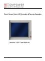
Touch Screen Color LCD Controller & Remote Operation Version 3.93 User Manual Empower RF Systems, Inc. Rev 3.3/3.8 EMPOWER RF SYSTEMS, INC. Touch screen Color LCD Controller & Remote Operation Copyright Empower RF Systems, Inc. 316 West Florence Avenue Inglewood, California 90301 USA Phone (310) 412-8100 • Fax (310) 412-9232 www.EmpowerRF.com Empower RF Systems, Inc. Rev 3.3/3.8 Ver 3.93 User Manual Rev 3.3/3.8 Touch screen Color LCD Controller& Remote Operation MODIFICATION RECORD Doc. Issue Date Paragraphs/Appendixes/Annexes changed and reason for modification Authorization Ref. Rev 2.0 6‐8‐09 Original release M.L. Rev 2.1 6‐9‐09 M.L. Rev 3.0 6‐10‐09 M.L. Rev 3.1 7‐14‐09 CDR package release M.L. Rev 3.2 8‐11‐09 M.L. Rev 3.8 11‐04‐09 Change S/W revision to 3.8. Change IL to IU Add band relation on IU and IX Band response Add SB command Change firmware version to 3.8 Update figures 1,2, 4, 5 Update table 1 – user configuration (band /output) Update table 2‐ remote commands: Update Band tables Update G min max values Typo in IU response Update IX command Update LD min max values Update LW min max values Update M antenna select response value Update SA selection value Add SM mapping information add table Add table for the VM monitor information Insert band table and SA with the appropriate command Insert previous table 3 (fault description) at the appropriate command User 3.91 FW 3.8 11‐13‐09 M.L. User 3.92 FW 3.8 4‐27‐10 Update typo on paragraph Fault condition on page 7 Edit Note on page 17 Update output select table in B command on page 11 Update band select table in B command on page 18 Update band select table in IX command on page 19 Update level (min) table in LD command on page 19 Update level (min) table in LW command on page 20 Update typo in B table and A table in M command on page 21 Update YYYY table in SS command on page 23. Change the baud rate information of fig. 7 on page 13. Change the text label of fig. 8 on page 15. Updated typos of frequency values on page 11, 18 and 19. Corrected command response definition on page 21. Updated the note on page 22. Added a query response code and corrected the fault description for the SS command on page 23. Added note for the VM command on page 24. User 3.93 24‐Feb‐2012 FW 3.3/3.8 Updated the Figures 1 thru 9 Edited tables 1&2 descriptions. Empower RF Systems, Inc. M.L. C.M. C.M. Page 3 of 26 Ver 3.93 User Manual Touch screen Color LCD Controller& Remote Operation Rev 3.3/3.8 Table of Contents 1 General Information ........................................................................................ 6 2 Display Panel Operation ................................................................................. 6 2.1 2.2 2.3 Splash Screen ................................................................................................................ 6 Front Panel Fault LED ................................................................................................... 6 Main Menu Screen ......................................................................................................... 7 2.3.1 2.3.2 2.3.3 2.3.4 2.3.5 2.4 User Configuration Menu Screen ............................................................................... 10 2.4.1 2.4.2 2.4.3 2.4.4 2.5 Status Window ....................................................................................................................... 7 Monitor Window...................................................................................................................... 7 Slider Bar................................................................................................................................ 9 Function Buttons .................................................................................................................... 9 Touch screen Lock Feature.................................................................................................. 10 RS-232 Communication Setting Screen............................................................................... 14 RS-422 Communications Settings Screen ........................................................................... 15 Mode Settings ...................................................................................................................... 17 IEEE/GPIB – 488.2............................................................................................................... 17 Startup Options Screen .............................................................................................. 18 2.5.1 2.5.2 2.5.3 2.5.4 2.5.5 Amp Off ................................................................................................................................ 18 Amp On ................................................................................................................................ 18 Amp Resume........................................................................................................................ 18 Amp Custom......................................................................................................................... 19 Take Snapshot ..................................................................................................................... 19 3 Saved Settings ............................................................................................... 19 4 Fault Reporting .............................................................................................. 19 5 Remote Operation ......................................................................................... 20 5.1 Remote Operation Considerations ............................................................................ 20 6 Amplifier Commands .................................................................................... 21 Empower RF Systems, Inc. Page 4 of 26 Ver 3.93 User Manual Touch screen Color LCD Controller& Remote Operation Rev 3.3/3.8 Table of Figures Figure 1: Splash Screen ............................................................................................................. 6 Figure 2: Main Menu Screen “UNLOCK” .................................................................................. 7 Figure 3: Monitoring Window Selections ................................................................................. 8 Figure 4: Fault Condition Window ............................................................................................ 8 Figure 5: Main Menu Screen “LOCKED” ................................................................................ 10 Figure 6: User Configuration Menu Screen ............................................................................ 11 Figure 7: User Configuration Menu Multi-band Enabled ....................................................... 11 Figure 8: User Configuration with Multi-Band Enabled......................................................... 12 Figure 9: Next Options Screen ................................................................................................ 12 Figure 10: RS-232 Communications Setting Screen ............................................................. 14 Figure 11: RS-422 Communications Settings Screen ........................................................... 15 Figure 12: Startup Options Screen ......................................................................................... 18 Empower RF Systems, Inc. Page 5 of 26 Ver 3.93 User Manual Rev 3.3/3.8 Touch screen Color LCD Controller& Remote Operation 1 General Information This amplifier system can be operated locally or remotely. For local operation, the LCD touch screen on the front panel is used. A unified command set simplifies changing from one operational mode to another. Certain features may not be available on all systems. 2 Display Panel Operation 2.1 Splash Screen When the amplifier is turned on, a Splash Screen appears. The lower portion of the screen shows the amplifier model number, serial number, firmware version, and any options included. Figure 1: Splash Screen Note: The Splash Screen also shows the “Code CRC” number. This is a unique number that identifies the “code” (i.e., the software) version installed, and validates that it has not been corrupted. Please write this number down for future reference. This number will be helpful for revision control purposes and to determine if the software has become corrupted. The amplifier compares this calculated value against the original value every time that it is turned on and reports a fault if they do not match. 2.2 Front Panel Fault LED A red LED on the front panel flashes if a fault condition exists (see the Fault Reporting section for more information). Empower RF Systems, Inc. Page 6 of 26 Ver 3.93 User Manual Rev 3.3/3.8 Touch screen Color LCD Controller& Remote Operation 2.3 Main Menu Screen After a few seconds, the Splash Screen is replaced with the Main Menu Screen. This screen is divided into four sections: Status Window Monitor Window Function Buttons Slider Bar Empower RF Amplifier Status Window Monitor Window 100W Amp Status: Mode: ALC Stby ALC Level: 50.0 dBm Fwd Pwr: 0.0 dBm Rfl Pwr: 0.0 dBm Online P/S Output Voltage 0.0 Volts -10 Full None 28.0 28.0 27.9 ALC Level in dBm 25 Units Mode Function Buttons Fine 50 Slider Bar Figure 2: Main Menu Screen “UNLOCK” 2.3.1 Status Window The blue Status Window shows the current operating parameters. These include whether the amplifier is Online or in Standby, the mode (ALC or VVA), the forward and reflected power, the gain setting or ALC level and, if band switches or other RF switches are included, which band is currently selected. Press anywhere in this window to open the User Configuration Menu Screen (described later). 2.3.2 Monitor Window Below the Status Window is the Monitor Window (in green). This window shows the values of the various parameters being monitored, such as the power supply voltage or a module’s current consumption. Scroll through the parameter windows using the up and down arrows. 2.3.2.1 Normal Operation The Monitor Window can be scrolled through each available measurement during normal operation. In the figure below, the Output Voltage, System Temperature, and Module Current are shown. The controller can monitor up to eight modules for current consumption. The up and down buttons are used to scroll through the available monitors. If no monitors are available in the device, then the message “No Monitors Configured” is displayed. For each monitor, the name of the monitor is displayed as well as its present reading (including the units). Empower RF Systems, Inc. Page 7 of 26 Ver 3.93 User Manual Rev 3.3/3.8 Touch screen Color LCD Controller& Remote Operation Also displayed are three, factory-measured “typical” values: one with no input to the amplifier (None), one with the amplifier set to 10dB below maximum (-10), and one set at maximum (Full). This allows comparison of the present reading with the expected values. Some monitor variables are automatically checked for fault conditions—others are available simply for viewing. Up to eight modules can be monitored; each may have one or two outputs (e.g., Module 1A and Module 1B). Figure 3: Monitoring Window Selections 2.3.2.2 Fault Condition If one or more faults occur, the Monitor Window turns red, lists the faults, and the fault light flashes. If there are four or more faults, only the first three are displayed. Touching the fault region acknowledges that the fault has been viewed. If there are more than three faults, then the remaining ones appear. Figure 4: Fault Condition Window Faults can limit the output of the amplifier to protect it from further damage, shut the amplifier down, or just act as warnings (see Fault Descriptions in SS remote command for more information). Empower RF Systems, Inc. Page 8 of 26 Ver 3.93 User Manual Rev 3.3/3.8 Touch screen Color LCD Controller& Remote Operation After all the faults have been acknowledged, the Monitor Window returns to Monitoring Mode (as shown in the previous figure). This return to Monitoring Mode may be useful when analyzing faults. The fault light will continue to flash if the fault is still present. There are three types of faults that the controller reports: systems faults, monitor faults, and digital faults. System faults include Code CRC invalid, calibration data corrupted, VSWR threshold exceeded, etc. Monitor faults are analog monitor readings that are outside factory-set limits. Digital faults are logic conditions that the controller monitors. Digital faults are also factory-set and are not viewable unless a fault occurs. 2.3.3 Slider Bar Below the Monitor Window is the Slider Bar. In VVA Mode, the slider controls the gain of the amplifier (in dB). The actual gain may vary slightly as a function of variables such as the operating temperature. The actual forward power should be the final determination of desired operation. In ALC Mode, this button sets the desired output level. Because this is done with closed loop control, it will maintain the requested output with a high degree of stability and the accuracy will be that of the forward power indicator. There is a Fine/Coarse button that toggles the slider range between fine and course adjustments (see the Fine/Coarse Button section for more information). 2.3.4 Function Buttons To the right of the two windows are four buttons: Online/Standby, Mode, Units, and Fine/Coarse. Pressing each button toggles the amplifier between one of two options. Online/Standby Mode Units Fine/Coarse – Toggles between Online Mode and Standby Mode. – Toggles between ALC Mode and VVA Mode. – Toggles between Watts and dBm display units. – Toggles between the Fine and Coarse Slider Bar adjustments. Some of the button names change when pressed. These names describe the option that will be selected by pressing the button. The currently selected option can be determined from the Status Window. 2.3.4.1 Online/Standby Button The Online/Standby button toggles between Online Mode and Standby Mode (Standby Mode automatically puts the amplifier in Receive Mode (Rx) if this option is implemented). If the amplifier has been shut down because of a critical fault, pressing this button will switch it to Standby Mode and clears the fault so that it can be switched to Online Mode again. 2.3.4.2 Mode Button The Mode button toggles between VVA Mode and ALC Mode. In VVA Mode, the amplifier operates at a user-settable gain. In ALC Mode, it attempts to maintain a constant RF output level regardless of gain drift or input changes. There are separate settings for VVA gain and ALC level, so that when switching between modes, it returns to the last value used for that mode. Empower RF Systems, Inc. Page 9 of 26 Ver 3.93 User Manual Rev 3.3/3.8 Touch screen Color LCD Controller& Remote Operation 2.3.4.3 Units Button The Units button toggles the display units between dBm and Watts. All internal values are stored and calculated in dBm with 0.01dB resolution. When Watts is selected, the Mode’s input and output are converted to (and from) Watts for the user’s convenience. (Note: VVA gain is always expressed in dB.) 2.3.4.4 Fine/Coarse Button The Fine/Coarse button toggles the slider range between fine and course adjustments. In Coarse Mode, the full operating range is available with approximately 300 steps of resolution. However, it may be difficult to set a value precisely in Coarse Mode. Switching to Fine Mode expands the scale for more accurate adjustments (initially centering the slider on the scale). If the desired value is off-scale, switching back to Coarse Mode and then to Fine Mode again will re-center the slider without changing the value. 2.3.5 Touch screen Lock Feature To prevent accidental changes to the amplifier, if no changes have been made for 15 seconds, the touch screen will lock. The display still shows operating values, but only two things can be touched: the Unlock button (to restore access to other controls), or the Online/Standby button (in case it becomes necessary to quickly shut down the amplifier). Figure 5: Main Menu Screen “LOCKED” 2.4 User Configuration Menu Screen The User Configuration Menu Screen allows changing a number of settings: LCD Contrast, GPIB, RS-232, RS-422, VSWR, Startup Mode, and ALC Speed. If no action is taken in this menu for 60 seconds, it automatically returns to the Main Menu. Empower RF Systems, Inc. Page 10 of 26 Ver 3.93 User Manual Rev 3.3/3.8 Touch screen Color LCD Controller& Remote Operation Figure 6: User Configuration Menu Screen Figure 7: User Configuration Menu Multi‐band Enabled (Firmware Version: 3.3) Empower RF Systems, Inc. Page 11 of 26 Ver 3.93 User Manual Rev 3.3/3.8 Touch screen Color LCD Controller& Remote Operation Figure 8: User Configuration with Multi‐Band Enabled (Firmware Version :3.8+) When the Next Options button is pressed, the following screen will be displayed: Figure 9: Next Options Screen Empower RF Systems, Inc. Page 12 of 26 Ver 3.93 User Manual Rev 3.3/3.8 Touch screen Color LCD Controller& Remote Operation Table 1. User Configuration Menu Parameters Parameter Description LCD Contrast Changes the contrast for the LCD using the up and down buttons from 0 to 99. GBIP Address Changes the GPIB address from 1 to 30 using the up and down buttons. RS-232 Parameters Displays the current RS-232 parameters by pressing the desired button which will access the respective Communications Settings Screen where its parameters can be changed. The parameters currently being used are shown on the button. RS-422 Parameters Displays the current RS-422 parameters by pressing the desired button which will access the respective Communications Settings Screen where its parameters can be changed. The parameters currently being used are shown on the button. VSWR Alarm Changes the VSWR alarm threshold from 2 to 10dB using the up and down buttons. Band Sets the band switch relays. These relays can be used as filters for different bands, for T/R switching, or for other purposes. If the amplifier is ON when the command is given, it is placed in Standby Mode temporarily so the relay will not be hot switched. Output Set the transmitting output. 100-1000MHz Amplifier BAND Select Filter 174 MHZ Filter 250 MHz Filter 415 MHz 174MHz 250MHz 415MHz Filter 700 MHz 700MHz Filter 1000 MHz 1.0GHz Startup Mode Options You can change the Startup Mode Options by pressing the Startup Mode Options button. This opens the Startup Options Screen. Change to Slow / Fast ALC Press the Change to Slow/Fast ALC options button to toggle between (and set) Slow or Fast ALC. Change to Slow ALC is useful for AM or other modulated signals where the ALC would remove part of the modulation if it responded too quickly. Change to Fast ALC provides better performance for FM or other modulations that do not vary in amplitude. Change to Slow ALC is designed to preserve amplitude changes down to 10Hz. Change to Fast ALC is designed to level in less than 100mSec. Fault Override When enabled, critical faults do not shut the amplifier down. This would be used for situations where amplifier operation is required even with critical faults and the value of continued operation exceeds the risk of damaging the equipment. CAUTION With this override enabled, IT IS POSSIBLE TO EASILY DAMAGE OR DESTROY THE AMPLIFIER. The user assumes complete responsibility for any damage resulting from the use of this option. Overridden faults are logged. This command could be given at the beginning of a critical operation, rather than after a fault occurs. This way uninterrupted operation is possible. Empower RF Systems, Inc. Page 13 of 26 Ver 3.93 User Manual Rev 3.3/3.8 Touch screen Color LCD Controller& Remote Operation Table 1. User Configuration Menu Parameters Parameter Description Previous Options Returns to the previous User Configuration Menu Screen. Next Options Displays more options. Done Returns to the Main Menu Screen. 2.4.1 RS‐232 Communication Setting Screen The RS-232 Communications Settings Screen opens from the User Configuration Menu Screen. This screen allows setting the speed (baud rate), number of data bits, parity, number of stop bits, and whether or not hardware handshaking is used. Select the desired setting by pressing the associated button. Figure 10: RS‐232 Communications Setting Screen When setting the communications parameters, be aware that different combinations can result in different numbers of bits per character. This, in turn, affects the throughput to a degree. For example, seven (7) data bits with no parity has fewer total bits than seven (7) data bits with even or odd parity. Eight (8) data bits with parity takes even more total bits. Hardware handshaking uses what is generally referred to as RTS/CTS handshaking (although this term is not totally accurate). The signal on pin 7 of the DB-9 connector determines whether the characters will be sent to the host. If they are not sent, they are buffered (up to 255 characters). If the buffer is full, all processing stops. Likewise, the controller has an incoming buffer of 255 characters. When incoming characters fill most of this buffer, the signal on pin 8 indicates to the host that no further characters should be sent until the ones in the buffer have been processed. Failure to do so will result in lost characters, resulting in garbled messages, leading to unpredictable results. Empower RF Systems, Inc. Page 14 of 26 Ver 3.93 User Manual Rev 3.3/3.8 Touch screen Color LCD Controller& Remote Operation It is not necessary to use hardware handshaking with this product. The buffer has capacity for 10 commands. Data is never sent without first being requested (except for a start-up message). The best approach is to send a command or request, and then wait for a reply before sending another one. This ensures that no overflow occurs on either side. Although this results in lower throughput, this is not a problem in most cases. If maximum throughput is required, send a small number of commands (keeping track of the count). As soon as a response is returned, send another command. As long as the number of commands for which no response has been received is bounded to some small number, overflow cannot occur (yet the full duplex communication channel is used to full advantage). This technique is called windowing. A variation of the technique is to send a set of commands (typically, six commands will be sent repeatedly). After sending, wait for the responses before sending another set. 2.4.2 RS‐422 Communications Settings Screen The RS-422 Communications Settings Screen opens from the User Configuration Menu Screen. Select a setting by pressing the associated button. Figure 11: RS‐422 Communications Settings Screen The Factory Set-up parameters: 38,400 baud, 8 data bits, no parity and one stop bit. RS-422 communications does have some advantages. The most significant advantage is that the transmit/receive paths each have two wires. They are differential, allowing longer distances and significantly improved noise immunity. Empower RF Systems, Inc. Page 15 of 26 Ver 3.93 User Manual Touch screen Color LCD Controller& Remote Operation Rev 3.3/3.8 RS-422 operates identically to RS-232, except that there is no hardware handshaking. However, there are a few hardware issues to be considered: 1. Each end of each pair needs a terminating resistor. The controller has a place for these resistors and they can be provided or left off depending on the need. 2. Although the signals are differential, they are NOT fully floating. They are still logic level and must share a common ground. The quality of the ground does not have to be ideal, but it must be present. The AC power line safety ground is adequate in many cases. The ground potential between devices on an RS-422 cable should not exceed a few volts (DC or AC, peak to peak). Communications errors will result if it is too high. If it is above 7 volts, damage to the circuitry is possible. 3. Since the signal is differential, the polarity is important. If it is backwards, communications is not possible. RS-422 is also used in situations where several devices share wiring. In this case, only the two devices at the ends of the shared cable should have terminating resistors. Devices in the middle should not. In addition, only one device can “talk” on the cable at a time. Since RS-422 has separate transmit and receive paths, there must be one or more “masters” that control one pair and one or more “slaves” that share control of the other pair. “Slaves” cannot “talk” to each other. The controller has an incoming buffer of 255 characters. When incoming characters fill most of this buffer, the signal on pin 8 indicates to the host that no further characters should be sent until the ones in the buffer have been processed. Failure to do so will result in lost characters, resulting in garbled messages, leading to unpredictable results. The buffer has capacity for 10 commands. Data is never sent without first being requested (except for a start-up message). The best approach is to send a command or request, and then wait for a reply before sending another one. This ensures that no overflow occurs on either side. Although this results in lower throughput, this is not a problem in most cases. If maximum throughput is required, send a small number of commands (keeping track of the count). As soon as a response is returned, send another command. As long as the number of commands for which no response has been received is bounded to some small number, overflow cannot occur (yet the full duplex communication channel is used to full advantage). This technique is called windowing. A variation of the technique is to send a set of commands (typically, six commands will be sent repeatedly). After sending, wait for the responses before sending another set. 2.4.2.1 RS-485 Communications Interface Considerations A variation of RS-422 is RS-485. RS-485 uses the same signaling levels as RS-422 but shares a single pair of wire. This allows any device to listen while any other device talks, but limits communications to half duplex. Empower RF Systems, Inc. Page 16 of 26 Ver 3.93 User Manual Touch screen Color LCD Controller& Remote Operation Rev 3.3/3.8 2.4.2.2 RS-422 and RS-485 Configuration Considerations In using either RS-422 or RS-485, commands require addressing so that only one listener responds to a command. They also require turning the transmit output ON to talk and OFF when they are not to talk. No sign-on message or other unexpected message is allowed. 2.4.3 Mode Settings For the reasons previously given, any system requiring multiple devices to share RS-422 communications requires custom programming to implement the necessary protocol. There are two Mode buttons on the RS-422 menu that affect this. One button is labeled Continuous, the other Multidrop. The Continuous button causes the transmit lines to remain active at all times. This is desirable when only two devices are communicating, as it minimizes garbage when no device is talking. The Multidrop button causes the transmitting device to “disconnect” from the bus whenever it is not talking (mandatory if more than one device can talk on that pair of wires). 2.4.4 IEEE/GPIB – 488.2 GPIB is inherently string-oriented. The same command form is used, but line endings can be any combination of CR/LF (NL) or EOI. Responses end with CR and LF, with EOI asserted during the LF. The default GPIB address is 5 (but it can be changed in the User Configuration Menu on the LCD and will be remembered even if the power is removed). GPIB command response forms have evolved to meet both needs and technology. Some devices are always listening (Listen Only) or always talking (Talk Only). Some can be requested to talk without any command being given and will repeatedly give either the same response or a current reading. The amplifier does not use any of these variations. A GPIB sequence must include the following four items (in the order shown): 1. The controller addresses the amplifier to Listen. 2. The controller sends a command message. 3. The controller addresses the amplifier to Talk. 4. The amplifier sends a response which the controller receives. Implicit in the previous list is Unlisten and Untalk commands after each phase. The Listen and Talk commands (as well as Unlisten and Untalk commands) are often hidden from the user (the software in the GPIB controller automatically generates them as part of a send message or receive message command). The important thing to recognize is that the amplifier must receive this sequence in the proper order. Be aware that the following alternatives do not work: Multiple queries of the amplifier without intervening commands. Attempting to receive data from the amplifier after the end of message (CR LF/NL or EOI) has been received from the amplifier. Attempting to send data to the amplifier after sending the end of message (CR LF/NL or EOI). Any of these attempts will result in no response from the amplifier and a timeout of the GPIB network. Empower RF Systems, Inc. Page 17 of 26 Ver 3.93 User Manual Rev 3.3/3.8 Touch screen Color LCD Controller& Remote Operation In addition to the commands common to all remote protocols, the GPIB port recognizes the industry standard command “*IDN?” and responds with the manufacturer and model number of the amplifier. 2.5 Startup Options Screen The Startup Options Screen opens from the User Configuration Menu Screen. From this screen you can select the power-up mode for the amplifier and take a “snapshot” (described later) of the current settings for backup. Figure 12: Startup Options Screen 2.5.1 Amp Off In some cases, it is desirable that the amplifier always power-up in Standby Mode. It may be possible to not have a load, or the operation may interfere with another transmitter. The Amp Off button ensures that the amplifier will always power-up in Standby Mode. All other parameters will remain as they were when power was removed. 2.5.2 Amp On In other cases, the equipment is unattended and it is important that it power-up in Online Mode every time. Press the Amp On button to set this up (again leaving other settings the way they were when power was last removed). 2.5.3 Amp Resume Some situations may work best if the amplifier powers-up in the same state that it was in when it powered down, including being in Online Mode or Standby Mode. Press the Amp Resume button to select this option. Empower RF Systems, Inc. Page 18 of 26 Ver 3.93 User Manual Touch screen Color LCD Controller& Remote Operation Rev 3.3/3.8 2.5.4 Amp Custom Finally, there may be cases where the power-down condition is irrelevant—it is better to power-up to a known starting condition. The Amp Custom button will accomplish this. All non-volatile parameters are saved as they are when the “snapshot” is taken and are loaded at system startup. 2.5.5 Take Snapshot To define the values for each control, set the amplifier up exactly the way needed and then press the Take Snapshot button. This saves a copy of all the settings that will be loaded at power-up. CAUTION Ensure that all settings are correct before pressing “Take Snapshot” (this includes pressing Amp Custom or the snapshot will include a different startup mode). If Amp Custom is pressed afterward, the next startup will be custom, but the following ones will revert to the startup mode in effect when the snapshot was taken. Every setting is included in the snapshot (from the LCD contrast to the baud rate). Ensure they are all set to the intended values. 3 Saved Settings All settings on the Main Screen, the User Configuration Screen, and subordinate screens are saved for 10 years (from the date of manufacture) in non-volatile memory and are backed up by a lithium battery. The Startup Options menu (accessed from the User Configuration Menu), determines how this operates. There are two considerations for Saved Settings: 1. Should the amplifier start up in Online Mode or in Standby Mode? 2. Should the other parameters remain what they were when last powered up, or should they return to a specific state? A suitable combination can then be chosen using the amplifier start up selections and the parameter selections. 4 Fault Reporting The amplifier includes sophisticated logic to monitor its operation, prevent damage from improper operation, and alert the operator to problems. When possible, it takes care of problems unobtrusively, such as limiting the output to safe power levels, and reducing power in the case of a failed module or excessive reflected power. However, some situations (such as “over current”) require shutting down the amplifier. Problems that the operator needs to be aware of are reported in several ways. The front panel LED flashes and the green Monitor Window is replaced by a red Fault Window with one or more faults displayed in it. However, more detailed information about faults can be obtained using the SS command with a remote interface (described in the Remote Operation section). Empower RF Systems, Inc. Page 19 of 26 Ver 3.93 User Manual Rev 3.3/3.8 Touch screen Color LCD Controller& Remote Operation 5 Remote Operation Remote operation can be performed using RS-422. The amplifier responds to character string messages. A message consists of: A command character (a letter from A to Z) An optional sub-command character (a letter from A to Z, or ?) A numeric parameter (for some commands) A line ending consisting of a Carriage Return (0x0D) Many of the commands have a query form where the second character is a question mark. The parameter will be a decimal number in ASCII form. One or more spaces can optionally precede the number. Watts are entered as integer values. The dB or dBm values are integers in hundredths of dBm (i.e., 51.4dB would be entered or shown as 5140). In cases such as a Band selection or a Mode change, the second character (sub-command) serves as the parameter. 5.1 Remote Operation Considerations Settings are stored in nonvolatile memory and remembered even when the unit is not powered. RS-422 is a character-oriented protocol at its lowest level, and the commands are implemented as strings of characters. The amplifier maintains transmit and receive buffers of up to 256 characters for more efficient operation. No action is taken until the line ending character is encountered. The line ending can alternatively be an LF (NL) character (0x0A) or the combination of both CR and LF. If the command is invalid, a “?” will be returned. If the command requires a response, it will be returned. Whatever response is given will be followed by a line ending consisting of CR and LF. The default RS-422 parameters are 38,400 baud, 8 data bits, no parity and one stop bit. It is important to respect the limits of the buffer. Good programming practice suggests waiting after each command to get a response before sending the next command. This will insure that the buffer is not overflowed, as well as making it easy to match the response with the command. In some situations, it may be desirable to issue commands before receiving the previous response. The buffer makes this possible (as long as a suitable protocol is followed). One possible protocol would be to “window” commands and responses. That is, keep a count of commands issued for which responses have not been received. No advantage is gained by issuing more than three commands for which responses have not been received, so three (3) is a good window limit. Another alternative is to have a set of commands for which responses are needed (e.g., Forward Power, Reflected Power and Status). Issue each of these commands and then wait for all the responses. Note: The elapse time from command received to command execute is 10ms provided that the amplifier in monitoring mode. At interactive mode (touch screen) the time elapse is up to 100ms Since characters arrive asynchronously, command response is 0 – 10 ms typical, 0 – 100 ms worst case. Actual command execution happens in microseconds, so is immaterial; the only exception would be Antenna switching, Band switching and online commands. 20 ms delay for relay settling is needed, the response is not sent (and no other control loop action taken) until that time is up. Empower RF Systems, Inc. Page 20 of 26 Ver 3.93 User Manual Touch screen Color LCD Controller& Remote Operation Rev 3.3/3.8 CAUTION Under NO circumstances should the controlling system ever simply issue commands as fast as possible without limits. Empower RF Systems, Inc. cannot assume any responsibility, either for supporting software developers who do so, or even for the proper operation of the amplifier. This technique will undoubtedly lead to buffer overflow. Once the buffer overflows, characters are lost, which changes the meaning of commands. Undesired effects will result, which could damage the amplifier or other equipment (e.g., the customer’s equipment). 6 Amplifier Commands The following remote commands are supported over all remote interfaces: Table 2. Remote Commands Command Description A<limit> Sets the VSWR Alarm threshold. <limit> is an integer representing 1/100dB units of return loss. Limit Minimum 600 (6dB return loss equal to 3.0:1). Maximum is 1000( 10dB return loss equal to 1.92:1) A? Returns the current Alarm setting. B<band> Sets the band switch relays. Valid bands are A, B, C, D, E, F, G, and H (provided that the appropriate number of bands has been defined). Example below: Multi- Band Amplifier Filter 174 MHZ BAND Select <band> 174MHz A Filter 250 MHz 250MHz B Filter 415 MHz 415MHz C Filter 700 MHz 700MHz D Filter 1000 MHz 1.0GHz E FO1234 Turns on Fault Override. The second character is the letter “oh”, not the digit zero. The password of 1234 helps prevent accidental enabling of the override. Any other form (such as FN or the wrong password) will shut off the override if it is ON. G<gain> Sets the amplifier gain by adjusting the VVA. <gain> is an integer representing 1/100dB. This number only applies in VVA Mode. If it is given in ALC Mode, it will be stored and used when VVA Mode is selected. If it is given when the amplifier is in Standby Mode, it will apply when the amplifier is switched to Online Mode. G? Returns the current gain setting. IM This is a query which returns the Manufacturer Name as a string. IN This is a query which returns the Model Number as a string. IS This is a query which returns the Serial Number as a string. IU This is a query which return the VVA min and MAX limits Empower RF Systems, Inc. Page 21 of 26 Ver 3.93 User Manual Touch screen Color LCD Controller& Remote Operation Rev 3.3/3.8 Table 2. Remote Commands Command Description IF band is provided it will return the value for the specified band, if not, it will return the value for the currently selected band Response – “IU VVA Min xxxx Max yyyy” The first character after the echo will be a space. There is one space in each gap shown, except before Max, where there are two spaces. xxxx is the lower limit expressed in dBm with two digits after an implied decimal point (e.g. 51 dB would be 5100), and yyyy is the upper limit in the same format IV This is a query which returns the Firmware Version as a string. IX This is a query which return the ALC MAX limits Or IF band is provided it will return the value for the specified band, if not, it will return the value for the currently selected band. Valid bands are 0,1,2,3,4,5,6 (provided that the appropriate number of bands has been defined) IX<band> Response – “IX Max = nnnn” The first character after the echo will be a space. There is one space in each gap shown. ‘nnnn is the upper limit in dB (e.g. 50 dB would be 5000) The lower limit is always 25 dB (2500) less than the upper limit Example below: Filter 174 MHZ 174MHz IX Code 0 Filter 250 MHz 250MHz 1 Filter 415 MHz 415MHz 2 Filter 700 MHz 700MHz 3 Filter 1000 MHz 1.0GHz 4 Amplifier BAND Select LD<level> Sets the desired output power in dBm. <level> is an integer in 1/100dBm units. This number only applies in ALC Mode. If it is given in VVA Mode, it will be stored and used when ALC Mode is selected. If it is given when the amplifier is in Standby Mode, it will apply when the amplifier is switched to Online Mode. LF Sets ALC to Fast Mode. This is the default and normal mode. LS Sets ALC to Slow Mode. This is useful for Amplitude Modulated signals, or other signals that have varying amplitude which the amplifier should not level. LW<level> Sets the desired output power in Watts. <level> is an integer in Watts. This number only applies in ALC Mode. If it is given in VVA Mode, it will be stored and used when ALC Mode is selected. If it is given when the amplifier is in Standby Mode, it will apply when the amplifier is switched to Online Mode. L? Returns the current ALC setting in current units. If Slow Mode is set, the word “Slow” is added. MA Switches the mode to ALC Mode (does not change the Online/Standby selection). MO Switches the mode to Online Mode. MS Switches the mode to Standby Mode. MV Switches the mode to VVA Mode (does not change the Online/Standby selection). Empower RF Systems, Inc. Page 22 of 26 Ver 3.93 User Manual Touch screen Color LCD Controller& Remote Operation Rev 3.3/3.8 Table 2. Remote Commands Command Description M? Returns the current mode. The response will be: “M? MSBA” where M - Mode is either ALC or VVA A - ALC V - VVA S - Amplifier is either Online or Standby O - Online S - Standby B - Active filter band A, B, C, D, E…. Example Below: 100-1000MHz Amplifier Filter 174 MHZ BAND Select B 174MHz A Filter 250 MHz 250MHz B Filter 415 MHz 415MHz C Filter 700 MHz 700MHz D Filter 1000 MHz 1.0GHz E A -Active Antenna Output 0,1,2 100-1000MHz Amplifier TX to External Load TX to Omni TX high band antenna A 0 1 2 PF Returns the Output power (forward). The format is identical to that used by "L?". PR Returns the Reflected (output) power. The format is identical to "L?". The best results will be obtained when the units are in dB. PV Returns the calculated (output) VSWR. Return value is from 100 (represent 1.00:1) to 999 (represent 9.99:1) . SA<n> Antenna Select. <n> a decimal digit. Valid selection 0,1,2,3. Example below: SA Antenna Select Load Antenna 1 Antenna 2 Antenna 3 SB<n> SA<n> 0 1 2 3 Alternate to B command. Sets the band switch relays. Valid bands are 0, 1, 2..15 (provided that the appropriate number of bands has been defined). SD Sets the units of power to dBm. Empower RF Systems, Inc. Page 23 of 26 Ver 3.93 User Manual Touch screen Color LCD Controller& Remote Operation Rev 3.3/3.8 Table 2. Remote Commands Command Description SM Shows a bit map of monitoring faults. The response is 8 hex digits followed by 4 hex digits. The first field is a bit map of the analog monitoring channels (1 represents the first channel, 2 the second, 4 the third, 8 the fourth, 16 the fifth, etc.). The second field represents digital fault channels using the same scheme. Response Bit Map Analog Monitoring Fault Bit Map Digital Monitoring Fault 00000000 0000 No Faults 00000000 0000 No Faults 00000001 0000 Power Supply Voltage Fault 00000000 0001 RF Module 1 Fault 00000002 0000 System Temperature Fault 00000000 0002 RF Module 2 Fault 00000004 0000 RF Module 1 Current Fault 00000000 0004 RF Module 3 Fault 00000008 0000 RF Module 2 Current Fault 00000000 0008 RF Module 4 Fault 00000010 0000 RF Module 3 Current Fault 00000000 0010 RF Module 5 Fault 00000020 0000 RF Module 4 Current Fault 00000000 0020 RF Module 6 Fault 00000040 0000 RF Module 5 Current Fault 00000000 0040 RF Module 7 Fault 00000080 0000 RF Module 6 Current Fault 00000000 0080 System Temperature Fault 00000100 0000 RF Module 7 Current Fault 00000000 0100 RF Module 8 Fault 00000200 0000 RF Module 8 Current Fault 00000000 0200 RF Module 9 Fault 00000400 0000 RF Module 4 Current Fault 00000000 0400 RF Module 10 Fault 00000000 0800 Driver Module Fault Note: Fault code can be combine together e.g – System Temperature Fault + RF Module 1 current fault will return 00000006 0000 Empower RF Systems, Inc. Page 24 of 26 Ver 3.93 User Manual Rev 3.3/3.8 Touch screen Color LCD Controller& Remote Operation Table 2. Remote Commands Command Description SS Show Status. SS OFI XX YYYY SS is echoed from the input. O - Amplifier is either Online or in Standby Mode as follows: O = Online S = Standby F - Fault type as follows: B – Both System and Group faults exist F – System fault(s) exist M – Monitoring fault(s) exist N – No faults exist I - Input signal condition as follows: P – Input signal present L – Input signal low or absent XX - A two-digit hexadecimal number identifying system faults as follows: 00 –No Fault 01 – Code CRC check failed 02 – Non-Volatile Calibration data is bad 04 – CPU fault 08 – VSWR Alarm 10 – ALC Fault 20 – An automatic monitor has caused power to be reduced 3dB or more. YYYY - A four digit hexadecimal number identifying group faults (monitor faults). The meaning of each bit depends on how monitors are set up with this amplifier.. Fault Status (YYYY) Fault Description HEX 0000 0001 0002 0004 0008 0010 Fault Status (YYYY) Fault Description HEX No Fault. Temperature Fault. Power Supply Voltage Fault Power Supply Current Fault Interlock Switch 1 or more RF Module Current Fault 0020 0040 0080 0100 0200 0400 RF Driver module Current Fault VSWR PRF Fault (Pulse Unit Only) N/A N/A N/A Note: Fault code can be combine together e.g. RF Module current fault + RF driver current fault will return 0030 ST Returns milliseconds since power-up, total elapsed power-up minutes, and total elapsed ONLINE minutes. SU Returns the current measurement units. Response is SU D (in dBm) or SU W (in Watts). Empower RF Systems, Inc. Page 25 of 26 Ver 3.93 User Manual Touch screen Color LCD Controller& Remote Operation Rev 3.3/3.8 Table 2. Remote Commands Command Description SW Sets the units of power to Watts. VM<MonChan> Reads and scales the value of the specified monitor channel. The results are in tenth units. The channel numbers range from 0 to 31 (although most amplifiers will not use all channels). Possible Responses Command Monitoring Value Command Monitoring Value VM 0 Power Supply Voltage Output VM 5 RF Module current VM 1 System Temperature VM 6 RF Module current VM 2 RF Module current VM 7 RF Module current VM 3 RF Module current VM 8 RF Module current VM 4 RF Module current Note: Possible response: PS Voltage 28028.0 Volts Temperature 25025.0 C Current 40 4.0 Amps VV Returns the version number of the firmware. Empower RF Systems, Inc. Page 26 of 26