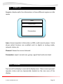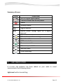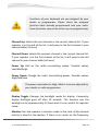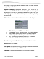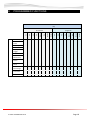
1
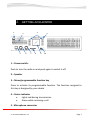
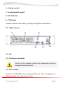
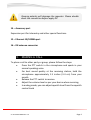
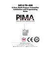
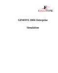
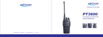
UHF FM DIGITAL REPEATER ST-9116D (450Mhz ~ 520Mhz) ST-9116C (400Mhz ~ 470Mhz) VHF FM DIGITAL REPEATER ST-9116V (136Mhz ~ 174Mhz) SmarTrunk Systems, INC. ST-9116UM R1.0 Printed in Malaysia FCC NOTICE This device complies with Part 15 of the FCC Rules. Operation is subject to the following two conditions: (1) This device may not cause harmful interference, (2) This device must accept any interference received, including interference that may cause undesired operation. FEDERAL COMMUNICATIONS COMMISSION INTERFERENCE STATEMENT This equipment has been tested and found to comply with the limits for a Class B digital device, pursuant to Part 15 of the FCC Rules. These limits are designed to provide reasonable protection against harmful interference in a residential installation. This equipment generates, uses and can radiate radio frequency energy and, if not installed and used in accordance with the instructions, may cause harmful interference to radio communications. However, there is no guarantee that interference will not occur in a particular installation. If this equipment does cause harmful interference to radio or television reception, which can be determined by turning the equipment off and on, the user is encouraged to try to correct the interference by one or more of the following measures: --Reorient or relocate the receiving antenna. --Increase the separation between the equipment and receiver. --Connect the equipment into an outlet on a circuit different from that to which the receiver is connected. --Consult the dealer or an experienced radio/TV technician for help. ST-9116 USER MANUAL R 1.0 Page 2 THANK YOU! We are grateful you chose SmarTrunk for your land mobile radio applications. We believe this powerful, flexible and easy-to-use repeater will provide dependable and reliable communications to keep personnel operating at peak efficiency. SmarTrunk transceivers incorporate the latest in advanced SDR technology. As a result, we feel strongly that you will be pleased with the quality and features of this product. NOTICES TO THE USER GOVERNMENT LAW PROHIBITS THE OPERATION OF UNLICENSED RADIO TRANSMITTERS WITHIN THE TERRITORIES UNDER GOVERNMENT CONTROL. ILLEGAL OPERATION IS PUNISHABLE BY FINE OR IMPRISONMENT OR BOTH. REFER SERVICE TO QUALIFIED TECHNICIANS ONLY. SAFETY: It is important that the operator is aware of and understands hazards common to the operation of any transceiver. WARNING: EXPLOSIVE ATMOSPHERES (GASES, DUST, FUMES, etc.) ST-9116 USER MANUAL R 1.0 Page 3 PRECAUTIONS Observe the following precautions to prevent fire, personal injury, and transceiver damage. - Do not modify this repeater for any reason. - Do not expose the repeater to long periods of direct sunlight, nor place it close to heating appliances. - Do not place the repeater in excessively dusty, humid, and/or wet areas, or on unstable surfaces. - If an abnormal odor or smoke is detected coming from the repeater, switch OFF the power immediately and remove the power supply connection to the repeater. Contact your SmarTrunk dealer. ST-9116 USER MANUAL R 1.0 Page 4 Table of Contents 1. UNPACKING AND CHECKING EQUIPMENT ..6 2. GETTING ACQUAINTED .....................................7 3. MAKING A CALL ...................................................9 4. DISPLAY ...............................................................10 4.1. ICONS...............................................................10 5. LED INDICATOR .................................................13 6. VOLUME SELECTOR ........................................14 7. PROGRAMMABLE BUTTONS FUNCTIONS .14 8. PROGRAMMED FUNCTIONS ..........................18 ST-9116 USER MANUAL R 1.0 Page 5 1. UNPACKING AND CHECKING EQUIPMENT Note: The following unpacking instructions are for use by your SmarTrunk dealer, an authorized SmarTrunk service facility, or the factory. Carefully unpack the repeater. We recommend that you identify the items listed in the following table before discarding the packing material. If any items are missing or have been damaged during shipment, file a claim with the carrier immediately. Supplied Accessories Item Smartrunk ST-9116 repeater Part number Quantity ST-9116X 1 DC cord for ST-9116 ST-9116DC 1 Microphone ST-3118NM 1 Screw set ST-9116SS 1 Instruction manual ST-3118UM 1 ST-9116 USER MANUAL R 1.0 Page 6 2. GETTING ACQUAINTED 1 3 2 5 6 7 8 4 9 10 1 – Power switch: Push to turn the radio on and push again to switch it off. 2 – Speaker 3 – Menu/programmable function key Press to activate its programmable function. The function assigned to this key is designed by your dealer 4 – Status indicator Lights red during transmission Green while receiving a call 5 - Microphone connector ST-9116 USER MANUAL R 1.0 Page 7 6 – Volume control 7 – Analog Squelch control 8 – SD CARD slot 9 – TFT display It shows relevant radio status, messages and general information. 10 – USB connector 13 12 11 14 15 16 11 – Fan 12 – TX antenna connector Never use the repeater without the appropriate antenna connected to this terminal. 13 – DC in (13.8V) Connect to ST-9116DC wires. Red to positive (+), black to negative (-). Please consider the max current is 15A. ST-9116 USER MANUAL R 1.0 Page 8 Reverse polarity will damage the repeater. Please double check the connection before apply DC. 14 – Accessory port Expansion port for telemetry and other special functions. 15 – Ethernet 10/100Mb port 16 – RX antenna connector 3. MAKING A CALL To place a call to other party or group, please follow the steps: Press the PTT switch in the microphone and speak in your normal speaking voice. For best sound quality at the receiving station, hold the microphone approximately 1.5 inches (3-4 cm) from your mouth. Release the PTT switch to receive. Adjust the volume level as per your desire when receiving. In analog mode, you can adjust squelch level from the squelch control knob ST-9116 USER MANUAL R 1.0 Page 9 4. DISPLAY Repeater display splits the information in three different regions on idle mode. Icons Channel name Parameters Icons: shows important information as RSSI, and transmit power. It also shows which features are enabled such as digital or analog mode, network status, etc. Channel: Shows the current channel. Parameters: report current user, group, signal level and voice level. 4.1. ICONS Top area of the display is reserved to display icons. These icons represent repeater status and are dynamically located on the icon area of the display. ST-9116 USER MANUAL R 1.0 Page 10 RSSI: Receive Signal Strength Indicator. Special care must be taken when the channel in digital mode because this indicator shows the RDSI (Receive Digital Signal Indicator) as average digital signal quality related to the BER (Bit Error Rate) on the channel and not the RSSI level. In transmit mode this icon shows an antenna and a letter indicating the real power transmit. Power: shows the transmit power Set. (L)ow, (M)edium,(H)igh,(A)uto. Alarm: in antenna is not matching the impedance, temperature is too high, intermod product detected or internal memory malfunctioning has been detected, then this icon appears into the display. Please call to your SmarTrunk qualified dealer to check the condition. Speaker: this Icon represents the presence of audio in the radio Speaker (External or internal), then the Icon implies the radio is reproducing receive audio (Analog or digital) on the speaker. This is only for receiving audio not for generated tones or radio announces. Analog mode: this Icon shows to the user if the current channel is an analog channel. Digital mode: this Icon shows to the user if the current channel is a digital channel. : Hybrid mode: This icon appears when the radio is operating on analog mode over a digital channel. Ethernet connection: this icon is displayed once the repeater is linked to the Ethernet network getting a valid IP. ST-9116 USER MANUAL R 1.0 Page 11 Ethernet connection: linked but not a valid IP or gateway has been configured. Fan active: if temperature is over the programmed trigger temperature, the fan will start blowing to cool down the unit. Power Save mode: If the power save mode has been enabled by repeater programming software, this icon will appears on the repeater display. SD Card Available: if a valid SD card is locked into the SD Card Socket, this icon will appears. USB: This icon is shown when the radio has a locked connection to any USB host or an USB charger. Voice logging: If the unit is recording a conversation, this icon will appears. ST-9116 USER MANUAL R 1.0 Page 12 Summary of icons: ICON FUNCTION RSSI or Digital Signal quality Transmit mode and current power Alarm Analog channel Digital channel Hybrid mode: analog signal on a digital channel Ethernet connection Ethernet connection warning Operational Fan USB connected Power save mode SD memory available Monitor open Voice recording \ 5. LED INDICATOR A tri-color led indicator has been added on your radio to visual communicate the following status. Lights red: while transmitting. ST-9116 USER MANUAL R 1.0 Page 13 Lights green: while receiving. Orange led blink: an unattended event is available. 6. VOLUME SELECTOR Rotate to adjust the volume. Volume selector controls audio level of any received audio, coming from RX, analog or digital, or IP port. 7. PROGRAMMABLE BUTTONS FUNCTIONS Each function and buttons can be programed as your desires. The functions of the front buttons (F1, F2, F3 and F4) and navigations keys (Up, Down, Menu and Enter) are override when the user enters the menu. There are many possibilities for each key, regarding the long or short push. The functions to each key are assigned for your dealer on programming time. ST-9116 USER MANUAL R 1.0 Page 14 Functions of your keyboard are pre-assigned by your dealer or programmer. Please check the assigned function table already programmed into your radio. Some functions may not be active in your programming. Channel Up: Selects the next channel in the current channel list. If your repeater is in the end of the list, it will jump to the first channel in your channel table (roll over) Channel Down: Selects the previous channel in the current channel list. If your repeater is in the first channel of the list, it will jump to the last channel in your channel table (roll over) Power Up: Roll on the radio transmitting power. Possible values, Low/Mid/High. Power Down: Change the radio transmitting power. Possible values, High/Mid/Low. The power associated to High, Med or Low are adjusted by your dealer or radio programmer. Display Toggle: Changes the backlight mode for display. Commonly, display backlight goes off after 20 seconds. This function sets the backlight on by approximately 12 hours and it is very useful for repeater setup. Monitor: Sets the repeater in monitor mode. In this case, all the channel activity is heard in the speaker. If there is no carrier on the frequency, ST-9116 USER MANUAL R 1.0 Page 15 white noise is heard on the speaker in analog mode. This mode overrides any signaling on the channel. Monitor Momentary: The monitor function is active as long as the button is pressed. When the button is released, the repeater squelch mode is back to normal. This option only takes effect if is set in the press and hold (long push mode). This mode temporary overrides any signaling on the channel. Status: This function report current repeater status on the display: DC-in: Displays current DC power voltage Temperature: current temperature of the TX power module Pwr Forward: shows the percentage of forward power in relationship to the calibrated power at installation time. Ant. Match: Shows the percentage of error of antenna calibration related to the installation time. Menu: has no operational functionality on current software version. Reset: Reboots the repeater. Slot Change: This function selects the time slot to be sent to the monitor when the repeater is receiving on TDMA mode. Link Status: This function sends the current IP link to the display. ST-9116 USER MANUAL R 1.0 Page 16 RSSI/RDSI: (Receive Signal Strength Indicator/ Receive Data Signal Indicator): Working on analog, voice report and display of current RSSI level. If the radio is working on any Digital Mode the reported information is the RDSI, which lets you know the real digital link quality. Notes: ST-9116 USER MANUAL R 1.0 Page 17 8. PROGRAMMED FUNCTIONS Key Channel Up Channel Down Power Up Power Down Display Toggle Monitor Monitor Momentary Status Reset Slot Change Link Status Menu ST-9116 USER MANUAL R 1.0 Page 18 Enter Up Down F4 Menu F3 F2 F1 Enter Up Long Push Down F4 Menu F3 F2 F1 Short Push ST-9116 USER MANUAL R 1.0 Page 19 Copyright 2014 Printed in Malaysia www.smartrunk.com ST-9116UM R1.0