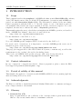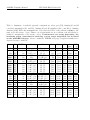
1
EUROPEAN SOUTHERN OBSERVATORY
Organisation Européene pour des Recherches Astronomiques dans l’Hémisphère Austral
Europäische Organisation für astronomische Forschung in der südlichen Hemisphäre
ESO - European Southern Observatory
Karl-Schwarzschild Str. 2, D-85748 Garching bei München
Very Large Telescope
Paranal Science Operations
AMBER Template Manual
Doc. No. VLT-MAN-ESO-15830-3523
Issue 96, Date 18/08/2014
Prepared
W.J. de Wit
18/08/2014
. . . . . . . . . . . . . . . . . . . . . . . . . . . . . . . . . . . . . . . . . .
Date
Approved
C. Dumas
. . . . . . . . . . . . . . . . . . . . . . . . . . . . . . . . . . . . . . . . . .
Date
Released
Signature
Signature
A. Kaufer
. . . . . . . . . . . . . . . . . . . . . . . . . . . . . . . . . . . . . . . . . .
Date
Signature
AMBER Template Manual
VLT-MAN-ESO-15830-3523
This page was intentionally left blank
ii
AMBER Template Manual
VLT-MAN-ESO-15830-3523
Change Record
Issue/Rev.
96
94
93
92.1
92
90
89
88
86
85
84
83
82
82
82
82
Date
Section/Parag. affected Remarks
18/08/15
26/05/14 2.4.1
13/11/13 Tab. 2
27/05/13 Tab. 2
27/02/13
2.3.3, Tab. 2
2.2.2
2.2.3
2.3.5
2.3.8
no changes
Polarization control
Recommended DITS
Update lim. mags
no changes
no changes
no changes
no changes
no changes
no changes
Medium Resolution in H band
FINITO use
Coude information
STRAP information
FINITO information
Execution time information
iii
AMBER Template Manual
VLT-MAN-ESO-15830-3523
This page was intentionally left blank
iv
AMBER Template Manual
VLT-MAN-ESO-15830-3523
v
.
.
.
.
.
.
.
.
.
.
.
.
1
1
1
1
1
1
2
.
.
.
.
.
.
.
.
.
.
.
.
.
.
.
.
.
.
.
3
3
3
4
4
5
5
5
6
6
6
6
8
8
9
9
9
11
11
13
Contents
1 INTRODUCTION
1.1 Scope . . . . . . . . . . . . . .
1.2 Contact information . . . . . .
1.3 Period of validity of this manual
1.4 Acknowledgments . . . . . . . .
1.5 Glossary . . . . . . . . . . . . .
1.6 Modifications for P96 . . . . . .
.
.
.
.
.
.
.
.
.
.
.
.
.
.
.
.
.
.
.
.
.
.
.
.
.
.
.
.
.
.
.
.
.
.
.
.
.
.
.
.
.
.
.
.
.
.
.
.
.
.
.
.
.
.
2 AMBER TEMPLATES
2.1 Observing modes . . . . . . . . . . . . . . . . . .
2.2 The acquisition template . . . . . . . . . . . . . .
2.2.1 Proper motion . . . . . . . . . . . . . . . .
2.2.2 Coudé guiding with the UTs . . . . . . . .
2.2.3 STRAP guiding with the ATs . . . . . . .
2.2.4 Source K and H magnitudes . . . . . . . .
2.2.5 Source K and H Visibilities . . . . . . . .
2.3 The observation template . . . . . . . . . . . . .
2.3.1 Integration time . . . . . . . . . . . . . . .
2.3.2 Using IRIS for Lab guiding . . . . . . . . .
2.3.3 Selecting the spectral band . . . . . . . . .
2.3.4 Additional spectral bands when FINITO is
2.3.5 FINITO . . . . . . . . . . . . . . . . . . .
2.3.6 Summary Table . . . . . . . . . . . . . . .
2.3.7 High SNR spectral calibration . . . . . . .
2.3.8 Execution time . . . . . . . . . . . . . . .
2.4 User keywords . . . . . . . . . . . . . . . . . . . .
2.4.1 AMBER 3Tstd acq.tsf . . . . . . . . . . .
2.4.2 AMBER 3Tstd obs 1row.tsf . . . . . . . .
.
.
.
.
.
.
.
.
.
.
.
.
.
.
.
.
.
.
.
.
.
.
.
.
.
.
.
.
.
.
.
.
.
.
.
.
. . . . . .
. . . . . .
. . . . . .
. . . . . .
. . . . . .
. . . . . .
. . . . . .
. . . . . .
. . . . . .
. . . . . .
. . . . . .
not used .
. . . . . .
. . . . . .
. . . . . .
. . . . . .
. . . . . .
. . . . . .
. . . . . .
.
.
.
.
.
.
.
.
.
.
.
.
.
.
.
.
.
.
.
.
.
.
.
.
.
.
.
.
.
.
.
.
.
.
.
.
.
.
.
.
.
.
.
.
.
.
.
.
.
.
.
.
.
.
.
.
.
.
.
.
.
.
.
.
.
.
.
.
.
.
.
.
.
.
.
.
.
.
.
.
.
.
.
.
.
.
.
.
.
.
.
.
.
.
.
.
.
.
.
.
.
.
.
.
.
.
.
.
.
.
.
.
.
.
.
.
.
.
.
.
.
.
.
.
.
.
.
.
.
.
.
.
.
.
.
.
.
.
.
.
.
.
.
.
.
.
.
.
.
.
.
.
.
.
.
.
.
.
.
.
.
.
.
.
.
.
.
.
.
.
.
.
.
.
.
.
.
.
.
.
.
.
.
.
.
.
.
.
.
.
.
.
.
.
.
.
.
.
.
.
.
.
.
.
.
.
.
.
.
.
.
.
.
.
.
.
.
.
.
.
.
.
.
.
.
AMBER Template Manual
1
VLT-MAN-ESO-15830-3523
1
INTRODUCTION
1.1
Scope
This document describes the templates for AMBER, the Astronomical Multi-BEam Recombiner,
of the VLT Interferometer. Like for all the VLT instruments, observations with AMBER are
carried out with observation blocks (OBs). The OBs must be written by the user during
Phase-2 preparation with the P2PP tool. An OB consists of a set of information and several templates that describe the target acquisition and the observation sequence. For some
templates, the user has to indicate the values of keywords (parameters).
This manual requires the user to already have an insight in the AMBER operation, as described
in the “AMBER User Manual”, that can be downloaded from:
http://www.eso.org/instruments/amber/doc
For the installation of the P2PP tool, see:
http://www.eso.org/observing/p2pp
Note: the AMBER specific templates will be downloaded by the P2PP tool.
For service mode observations, it is important to read the AMBER-specific service mode
instructions given on the web page:
http://www.eso.org/observing/p2pp/AMBER/AMBER-P2PP.html
This page gives suggestions for OB edition with P2PP (name, constraint set), as well as the
requirements for the “readme” file and for the finding charts.
There is also an AMBER P2PP specific web page with a step by step tutorial at:
http://www.eso.org/observing/p2pp/tutorials/tut amber.html
1.2
Contact information
In case of questions or suggestions related to Phase-2 preparation, please contact the ESO
User Support Department ([email protected]).
1.3
Period of validity of this manual
This manual only applies for observations with AMBER in ESO Period 96, starting April 1st,
2014 and ending October 1st, 2014.
1.4
Acknowledgments
The Editor would like to thank Stan Stefl and Markus Wittkowski for comments and suggestions of improvements to the manual.
1.5
Glossary
• Constrain Set (CS)
Listq of requirements for the conditions of the observation that is given inside an OB.
OBs are only executed under this set of minimum conditions.
AMBER Template Manual
VLT-MAN-ESO-15830-3523
2
• Observation Block (OB)
An Observation Block is the smallest schedulable entity for the VLT. It consists of a
sequence of Templates. Usually, one Observation Block include one target acquisition
and up to three exposure templates.
• Observation Description (OD)
A sequence of templates used to specify the observing sequences within one or more
OBs.
• Observation Toolkit (OT)
Tool used to create queues of OBs for later scheduling and possible execution (service
mode).
• Proposal Preparation and Submission (Phase-I)
The Phase-I begins right after the CfP (Call-for-Proposals) and ends at the deadline for
CfP. During this period the potential users are invited to prepare and submit scientific
proposals. For more information, see:
http://www.eso.org/observing/proposals.index.html
• Phase-2 Proposal Preparation (P2PP)
Once proposals have been approved by the ESO Observation Program Committee (OPC),
users are notified and the Phase-2 begins. In this phase, users are requested to prepare
their accepted proposals in the form of OBs, and to submit them by Internet (in case
of service mode). The software tool used to build OBs is called the P2PP tool. It is
distributed by ESO and can be installed on the personal computer of the user. See:
http://www.eso.org/observing/p2pp.
• Service Mode (SM)
In service mode (opposite of the “Visitor-Mode”), the observations are carried out by
the ESO Paranal Science-Operation staff (PSO) alone. Observations can be done at any
time during the period, depending on the CS given by the user. OBs are put into a
queue schedule in OT which later sends OBs to the instrument.
• Template
A template is a sequence of operations to be executed by the instrument. The observation software of an instrument dispatches commands written in templates not only to
instrument modules that control its motors and the detector, but also to the telescopes
and VLTI sub-systems.
• Template signature file (TSF)
File which contains template input parameters.
• Visitor Mode (VM)
The classic observation mode. The user is on-site to supervise his/her program execution.
1.6
Modifications for P96
There are additional modifications to table 2 regarding the recommended DIT for various
settings.
AMBER Template Manual
2
VLT-MAN-ESO-15830-3523
3
AMBER TEMPLATES
2.1
Observing modes
As indicated in the “AMBER web pages” found at:
http://www.eso.org/instruments/amber/inst/index.html
the following setups of AMBER will be offered for P96:
• 18 spectral modes available:
1. Low Resolution JHK using IRIS, where 30% of K is always sent to IRIS.
2. Medium Resolution K-band, center wavelength 2.1µm.
3. Medium Resolution K-band, center wavelength 2.3µm.
4. Medium Resolution H-band, center wavelength 1.65µm.
5. High Resolution K-band, with 14 central wavelengths (see Table 1).
• Table 2 gives a summary of the possible DITs that can be used depending on telescopes,
FINITO, and/or differential mode. The user can also check the latest on line information
at: http://www.eso.org/instruments/amber/inst
as this information supersedes any numbers presented in this manual.
• Coudé guiding on the science target or a guide star. It should be noted that without
MACAO the flux will be severely time dependent and will not reach the magnitude
limits given in this document or in the CfP. For proper AMBER observations Coudé
guiding must be used. For proper MACAO operation the SCIENCE target or the guide
star must be suitable for guiding (see section 2.2.2). Similar constraints for the STRAP
are given in section 2.2.3.
• Only baselines with three UTs or three ATs (3T template).
• Only one read-out mode (1 row) on the detector.
• External fringe tracker (FINITO) is available both on the ATs and the UTs. See section 2.3.5 for the constraints that must be fulfilled for FINITO fringe tracking. FINITO
is standard for MR and HR modes. OBs in MR or HR without the use of FINITO
should be submitted with an approved waiver.
Hence, the number of templates for P96 is minimal: one template for the preset, acquisition
and fringe search, and one template for fringe observation. Moreover, because of the policy
adopted by ESO for observations with AMBER in service mode (one calibrated visibility point
every 60 minutes), the number of keywords to be set by the user is very limited.
2.2
The acquisition template
According to P2PP rules, the first template in an OB must be an acquisition template. In the
case of AMBER, the name of this template is: AMBER 3Tstd acq.
The sequence of this template starts by a “preset”: the target coordinates (α, δ) are sent to
the telescopes and the delay lines, so they can slew to the position corresponding to the target
AMBER Template Manual
VLT-MAN-ESO-15830-3523
4
coordinate at preset time. Once the telescopes are tracking and Coudé-guiding, the target
should be seen on the Image Alignment Sensor, currently IRIS. To ensure that the beams are
injected properly to AMBER the Image Alignment Sensor is used to align the object to the
VLTI reference points (“image optimization”). To ensure that maximum flux is injected an
“injection adjustment” is done. This is done by sending offsets to the telescopes to maximize
the flux injected into the AMBER fibers.
2.2.1
Proper motion
In particular in Low resolution mode it is critical to have the information on the observed
proper motion of the object as a proper motion larger than 50 mas/year can slow down or
impede the fringe search. For an effective use of the allocated time we strongly suggest that
the known proper motions are incorporated into the OBs.
2.2.2
Coudé guiding with the UTs
It is possible to have an object different from the science target as a guide star at the Coudé
focus. The requirements are:
• The guide star must be brighter than V = 17 (MACAO is used for Coudé guiding). Note
that the Strehl drops significantly in K with a Coudé guide star fainter than the 13-14th
magnitude (approximately 1 magnitude) and that by magnitude 16th the magnitude
limits for the science object drops by more than 2 magnitudes.
• The guide star must be within a radius of 57.5 arcsec from the science target. Note that
the Strehl drops with distance from the science target, so it is recommended that the user
chooses a Coudé guide star as close as possible. If at distances larger than a few tens of
arcseconds from the science target more than 1 magnitude can be lost. A rule of thumb
is that the magnitude limits drops by 1 magnitude for every 15 arcseconds from the
science object. Note that when using FINITO the allowed distance is severely restricted,
see section 2.3.5. Note that the magnitude limit is changed when using FINITO, see
section 2.3.5.
• The guide star must be fainter than V = 1.
• It is requested that the faintest (if variable) V magnitude of the Coudé guide star is
given in the keyword TEL.COU.MAG.
• There are a few additional weather condition constraints for proper MACAO performance, which are also important even though the SCIENCE object is used for the
Coudé guiding:
– Seeing should be better than 1.5 arc sec.
– τ0 >1.5 ms
– Airmass <2.
These constraints do not affect Service observations as OBs are only classified as A or
B if MACAO has been performing within the tolerances. The constraints are given here
for Visitor mode observations to give the user the conditions under which MACAO will
perform as expected. Thus during non ideal weather conditions outside the MACAO
AMBER Template Manual
VLT-MAN-ESO-15830-3523
5
performance ranges the user could ameliorate the effects to some degree by only using
bright guide stars and only observing at a high elevation.
Note: The magnitude limits are identical for Coudé guiding on the SCIENCE target, and are
different from the limiting magnitudes for the AMBER instrument. Note: A plot of the
expected Strehl as function of guide star magnitude, distance and weather conditions is shown
in Figure 1
Note: To inject light into AMBER a Coudé guide star must be used. It is not possible under
any weather conditions to perform AMBER observations not using MACAO on the UTs.
2.2.3
STRAP guiding with the ATs
Note: To inject light into AMBER a guide star must be used with STRAP. It is not possible
under any weather conditions to perform AMBER observations not using STRAP on the ATs.
The requirements for successful STRAP guiding are:
• The guide star must be brighter than V = 13. Note that the tip tilt correction drops
significantly in K with a STRAP guide star fainter than the 11th magnitude and that
by magnitude 13th the magnitude limits for the science object drops by more than 1
magnitude.
• The guide star must be within a radius of <60 arcseconds from the science target. Note
that the effective tip-tilt correction drops with distance from the science target, so it
is recommended that the user chooses a guide star as close as possible. If at distances
larger than a few tens of arcseconds from the science target more than 1 magnitude can
be lost. A rule of thumb is that the magnitude limits drops by 1 magnitude for every
15 arcseconds from the science object. Note that with FINITO operation the distance
is severely limited, see section 2.3.5.
• It is requested that the faintest (if variable) V magnitude of the guide star is given in
the keyword TEL.COU.MAG. This is true for all cases when STRAP is used.
2.2.4
Source K and H magnitudes
The SEQ.SOURCE.HMAG and SEQ.SOURCE.KMAG keywords should be used to specify the uncorrelated H and K band fluxes of the science target.
2.2.5
Source K and H Visibilities
The SEQ.SOURCE.HVIS and SEQ.SOURCE.KVIS keywords should be used to specify the minimum visibility on the two shortest baselines for the science target in the requested LST
range. It is critical that these numbers are correct as possible since they are used to configure
FINITO and in particular too optimistic numbers can impede proper FINITO operation. It is
safer to underestimate the Visibility as the FINITO operation can adapt to higher Visibilities
than expected (although with possible reduced performance).
The final step in the Acquisition template is to search for fringes (“fringe search”). If FINITO
is used then the fringe search will be performed by FINITO and if not selected then it is done
by AMBER by doing a saw tooth search around the nominal fringe position. Note that there
are no user keywords available for this step.
AMBER Template Manual
2.3
VLT-MAN-ESO-15830-3523
6
The observation template
This template is the second and the last one (although see section 2.3.4 and section 2.3.7) in
any AMBER OB description for P96. It is used to record the photometric beams and the
dispersed fringes. There is currently only one template:
1. 3T exposures using 1 readout row on the detector, AMBER 3Tstd obs 1row.
Each exposure consists of one dispersed photometric spectrum for each telescope and one
dispersed fringe spectrum. The standard observation template takes 7 exposures, one dark
(DARK), five on source exposures (OBJECT), and, one off-source exposure (SKY).
The TEL.OFFS.ALPHA and TEL.OFFS.DELTA are used to select the location of the off target
exposure. These offsets will move the telescopes in the directions given.
2.3.1
Integration time
If the object is too faint/resolved/high Airmass for FINITO operation the integration times
with AMBER will have to be short to minimize atmospheric turbulence. It is foreseen to use
a DIT of 0.025 s (0.05 and 0.1 s available on the ATs) for all observations. The exception to
this rule is the use of differential phase observations and High Resolution K observations. In
these cases it is possible to use a DIT twice the standard DIT, i.e 0.05 s on the UTs and 0.1 s
on the ATs.
Note: The DIT of the Science and Calibrator targets must be identical to avoid biasing the
data.
Note: As a consequence the magnitude of the Calibrator is strongly suggested to be within
±0.5-1 (uncorrelated) magnitude of the science target.
Both the issues above are to avoid the biasing that is caused by having different detector
read-out levels on the Science and Calibrator.
2.3.2
Using IRIS for Lab guiding
IRIS is always used for lab guiding. This ensures that the slow tunnel tip-tilt effects are
corrected. The H flux is sent undiminished to AMBER while 30% of the K band flux is used
for the IRIS guiding. This magnitude loss is included in the given magnitude limits.
2.3.3
Selecting the spectral band
There are 18 available spectral configurations available for AMBER. The low resolution (LR)
covers the full spectral band of the instrument with R∼35, while the medium resolution grating
(MR, with R∼1500) can currently be configured for two wavelength ranges in the K-band and
one in H-band, and the high resolution grating (HR, with R∼12000) can currently be configured for 14 wavelength ranges. The user should select the proper spectrograph configuration
depending on the desired observing wavelength (see table 2.3.3). When FINITO is used the
full covered wavelength range is read out. In case FINITO is NOT used, an upper and lower
limits of the spectral range needs to specified. Due to the fixed DIT of 0.025 s (or 0.05 s for differential phase observations, see “AMBER User Manual”) the total spectral range is 0.04 µm
in MRK and 0.008 µm in HR and twice that for DIT=0.05 s). These are set by the keywords:
OCS.DET.ROW0.WLENMAX and OCS.DET.ROW0.WLENMIN in the AMBER 3Tstd obs 1row.tsf template.
AMBER Template Manual
VLT-MAN-ESO-15830-3523
7
Table 1: Allowed spectral configurations and spectral ranges. The maximum ∆λ, should be
used to determine the WLENMIN/MAX for the observing template. The numbers are all
given for DIT=0.025 s and should be scaled accordingly if DIT is increased i.e DIT=0.05s
allows twice the ∆λ so that in MR would be 0.08 µm.
Spectral Configuration
Low JHK
Medium K 1 2.1
Medium K 1 2.3
Medium H 1 1.65
High K 1 1.979
High K 1 2.018
High K 1 2.056
High K 1 2.095
High K 1 2.133
High K 1 2.172
High K 1 2.211
High K 1 2.249
High K 1 2.288
High K 1 2.326
High K 1 2.365
High K 1 2.403
High K 1 2.442
High K 1 2.481
Covered wavelength range Maximum ∆λ
[µm]
[µm]
1.027–2.54 µm
Full range
1.926-2.275 µm
0.04 µm
2.126-2.474 µm
0.04 µm
1.540-1.822 µm
0.032 µm
1.955-2.003 µm
0.008 µm
1.994-2.042 µm
0.008 µm
2.032-2.079 µm
0.008 µm
2.071-2.118 µm
0.008 µm
2.110-2.156 µm
0.008 µm
2.149-2.195 µm
0.008 µm
2.187-2.235 µm
0.008 µm
2.226-2.272 µm
0.008 µm
2.265-2.311 µm
0.008 µm
2.303-2.348 µm
0.008 µm
2.342-2.387 µm
0.008 µm
2.381-2.425 µm
0.008 µm
2.420-2.464 µm
0.008 µm
2.459-2.503 µm
0.008 µm
AMBER Template Manual
VLT-MAN-ESO-15830-3523
8
An example of the proper setting of the keywords for a template observing with Medium K 1 2.1,
centered around λ2.16µm without FINITO would be:
• DET1.DIT = 0.025
• OCS.DET.ROW0.WLENMAX = 2.18
• OCS.DET.ROW0.WLENMIN = 2.14
Note: Using FINITO in MR or HR the full spectral range can be used in all cases and the
values for the above keywords should be 9999 and 0.
2.3.4
Additional spectral bands when FINITO is not used
When FINITO is not used, and only parts of the spectral setting can be read-out, it is
still possible to obtain visibility measurements at several spectral positions inside the range
allowed by each configuration. This will allow to obtain calibrated visibilities on a line and
the surrounding continuum. In this case the user adds one AMBER 3Tstd obs 1row template
after the last observation template.
Note: This is only possible if the same spectral configuration is kept, and is limited to two
additional observation templates, ie, a total of three observing templates in the same OB. It
should also be stressed that the same observing configuration should be used for the calibrator.
2.3.5
FINITO
FINITO is offered on the Auxiliary Telescopes (ATs) and on the Unit Telescopes (UTs).
FINITO scans the center of the fringe packet in H band with high speed and sends a cophasing signal to the VLTI Delay Lines via a dedicated high speed link. Due to the short
individual exposure times (between 0.5ms and 2ms) and the need to measure the fringe in
every individual scan, the sensitivity of FINITO is somewhat worse than for AMBER in Low
Resolution mode that slowly records the fringe and can reject some data. FINITO operates
on two channels, i.e. tracks three baselines. Note that if FINITO is used then it takes either
70% or 100% of the H-band flux. This will only affect the LR-JHK and MR-H modes, as in
MR-K or HR-K the 100% dichroic is used and for LR-JHK the 70% one is used, thus loosing
1.3 magnitudes in the H-band. The observer should take this loss into account when setting
the DIT in the template.
The full potential of FINITO comes with AMBER using higher spectral resolution i.e Medium
and High Resolution. Since the fringes are ”frozen” in OPD space, AMBER can integrate
longer and/or one can stack the individual fringes during post processing.
Currently, FINITO operations are feasible under the following conditions:
• Seeing below 1.2 arcseconds on the ATs and below or equal to 0.8 arcseconds on the
UTs.
• The transparency should be CLR or better.
• τ0 above 2.5ms
• Airmass less than 1.5.
AMBER Template Manual
VLT-MAN-ESO-15830-3523
9
• The limiting correlated magnitude for FINITO is H=5 on the ATs and H=8 on the UTs
in LR or MR. In HR, the limits are H=5 on the ATs and H=7 on the UTs (see here) for
limiting magnitudes in various set conditions).
• The minimum visibility in the H band is 15% on the ATs and 10% on the UTs.
• The limiting V magnitude for the Coude guide star is severely reduced when using
FINITO. It is V=11 on the ATs and V=13 on the UTs.
• The distance to the Coude guide star (if different from the Science object) is severely
limited when using FINITO. For both the UTs and the ATs the maximum distance is
15 arcseconds.
These numbers were determined with a seeing less than 1.2 arcseconds and τ0 above 2.5ms.
The usage of FINITO is set by the TEL.DEL.FTSENSOR keyword in the ACQ template. To use
it the keyword value should be changed from the default NONE to FINITO.
FINITO should always be used in HR and MR, since the limiting factor is then AMBER.
Moreover, using FINITO thus allows AMBER to:
• Read-out the full spectral range in Medium and High Resolution: The user should thus
specify the full spectral range using:
– OCS.DET.ROW0.WLENMAX = 9999
– OCS.DET.ROW0.WLENMIN = 0
• Use longer than normal DITs (up to 6 s for conditions in Table 2). Note though that the
DIT must be the same on the Calibrator as on the Science object.
• See the AMBER webpages for limiting magnitudes in various set conditions.
• Stabilize the fringes in low resolution, so that higher quality data can be recorded.
2.3.6
Summary Table
Table 2 summarizes the current AMBER/AMBER+FINITO limits and possible configurations
assuming nominal weather conditions.
2.3.7
High SNR spectral calibration
In the two MRK modes an added high SNR observation will be performed at the end of the
final observing template. Its purpose is to allow later correction of the spectra by the user
in the offline data reduction. This observation covers the full MRK band in question and is
delivered automatically and requires no user input.
2.3.8
Execution time
The execution time for one uncalibrated visibility is fixed to 20 minutes. Users interested in
obtaining visibility measurements at several spectral positions inside the range (when FINITO
is not used) allowed by each configuration should add 15 minutes for each additional spectral
band. Each band will be defined by its minimum and maximum wavelength, with a span
AMBER Template Manual
VLT-MAN-ESO-15830-3523
10
Table 2: Summary of available spectral configurations, telescopes (Tel), limiting K and H
correlated magnitudes (Kc and Hc ), limiting K and H visibilities (KV is and HV is ), limiting
Airmass (AM), DITs and maximum ∆λ. Note that the DIT for the calibrator must be the
same as for the science object. Thus to avoid systematic errors a calibrator should ideally be
within 0.5 magnitudes of the science object. Performances are seeing dependent, the
maximum seeing constraint for observing a given target magnitude can be found
on the AMBER webpage. Please consult the AMBER web page for updated numbers for
degraded seeing conditions.
Mode
Tel
FINITO
LR
LR
LR
MRH
MRH
MRK
MRK
HRK
HRK
HRK
HRK
HRK
LR
LR
LR
LR
MRH
MRH
MRK
HRK
HRK
HRK
HRK
UT
UT
UT
UT
UT
UT
UT
UT
UT
UT
UT
UT
AT
AT
AT
AT
AT
AT
AT
AT
AT
AT
AT
no
yes
yes
yes
yes
yes
yes
yes
yes
yes
yes
yes
no
no
no
yes
yes
yes
yes
yes
yes
yes
yes
Kc
Hc
Kc ≤9.0
Hc ≤9.0
Kc ≤7.5
Hc ≤7
7.5<Kc ≤8.5
Hc ≤8
NA
Hc ≤5.5
NA
5.5<Hc ≤6.5
Kc ≤7.5
Hc ≤7
7.5<Kc ≤8.5
Hc ≤8
Kc ≤3.5
Hc ≤6
3.5<Kc ≤4.5
Hc ≤6
4.5<Kc ≤5.5
Hc ≤6
5.5<Kc ≤6.5
Hc ≤6
6.5<Kc ≤7.5
Hc ≤7
Kc ≤4.0
Hc ≤4.5
4.0<Kc ≤5.0 4.5<Hc ≤5.5
5.0<Kc ≤6.5 5.5<Hc ≤6.5
Kc ≤6.0
Hc ≤5
NA
Hc ≤2
NA
2<Hc ≤4.5
Kc ≤6.0
Hc ≤5
Kc ≤0.5
Hc ≤5
0.5<Kc ≤1.5
Hc ≤5
1.5<Kc ≤2.5
Hc ≤5
2.5<Kc ≤6.0
Hc ≤5
KV is
HV is
AM
≥0.1
≥0.1
≥0.1
NA
NA
≥0.1
≥0.1
≥0.1
≥0.1
≥0.1
≥0.1
≥0.1
≥0.05
≥0.05
≥0.05
≥0.05
NA
NA
≥0.05
≥0.05
≥0.05
≥0.05
≥0.05
≥0.1
≥0.1
≥0.1
≥0.1
≥0.1
≥0.1
≥0.1
≥0.1
≥0.1
≥0.1
≥0.1
≥0.1
≥0.05
≥0.05
≥0.05
≥0.15
≥0.15
≥0.15
≥0.15
≥0.15
≥0.15
≥0.15
≥0.15
≤2.0
≤1.5
≤1.5
≤1.5
≤1.5
≤1.5
≤1.5
≤1.5
≤1.5
≤1.5
≤1.5
≤1.5
≤2.0
≤2.0
≤2.0
≤1.5
≤1.5
≤1.5
≤1.5
≤1.5
≤1.5
≤1.5
≤1.5
∆λ DIT
[µm]
[s]
Full 0.025
Full 0.05
Full
0.1
Full
0.2
Full
0.5
Full
0.2
Full
0.5
Full
0.2
Full
0.5
Full
1.0
Full
3.0
Full
3.0
Full 0.025
Full 0.05
Full
0.1
Full 0.05
Full
0.2
Full
0.5
Full
0.2
Full
0.2
Full
1.0
Full
3.0
Full
6.0
AMBER Template Manual
VLT-MAN-ESO-15830-3523
11
of 0.04µm in MRK, 0.032µm in MRH and 0.008µm in HR. A maximum of 3 bands can be
accommodated within one observation ie at total execution time of 100 minutes for a CAL-SCI
sequence. Each change of configuration, or a number of bands exceeding 3, will require a new
acquisition, ie, 20 minutes per uncalibrated visibility.
Note: The calibrator has to be observed with the same configuration and thus the total
execution time for one calibrated visibility spectrum is 60 minutes for one calibrated visibility
(CAL-SCI-CAL). If for example the user has two spectral bands the total time for one SCICAL is 70 minutes. See also the ESO webpages for overheads.
2.4
User keywords
In the following tables, we give for each template the keywords that have to be set by the user
with the P2PP tool.
2.4.1
AMBER 3Tstd acq.tsf
Parameter
SEQ.SOURCE.HMAG
Range (Default)
Label
-5. . . 30 (0)
SEQ.SOURCE.HVIS
0. . . 1 (0.7)
SEQ.SOURCE.KMAG
-5. . . 30 (0)
SEQ.SOURCE.KVIS
0. . . 1 (0.7)
TEL.DEL.FTSENSOR
TEL.TARG.ADDVELALPHA
NONE
FINITO
(NONE)
-15. . . 15 (0)
TEL.TARG.ADDVELDELTA
-15. . . 15 (0)
TEL.COU.ALPHA
TEL.COU.DELTA
TEL.COU.GSSOURCE
RA (0.)
DEC (0.)
SETUPFILE SCIENCE (SCIENCE)
TEL.COU.MAG
0. . . 25 (0.)
DPR.CATG
OCS.OBS.SPECCONF
SCIENCE CALIB (SCIENCE)
Low JHK
Medium K 1 2.1
Medium K 1 2.3
Medium H 1 1.65
(NODEFAULT)
NONE LB>1M (NONE)
Source uncorrelated H magnitude
Source minimum H Visibility for
the requested LST range
Source uncorrelated K magnitude
Source minimum K Visibility for
the requested LST range
Using FINITO as external fringe
tracker or not.
Differential RA tracking in arcsec/sec.
Differential DEC tracking in arcsec/sec.
RA of a guide star.
DEC of a guide star.
Coudé guide star, this can be
either the science object (SCIENCE), a guide star (SETUPFILE), or no Coudé guiding
(NONE). See section 2.2.2.
Guide star magnitude in V. This
must be supplied and in the case
of a variable star the maximum
magnitude should be given.
Science or calibrator OB.
Spectral configuration
INS.OPTI2.NAME
AMBER
Polarizing element
Below follows a more detailed description of the keywords in the acquisition template:
AMBER Template Manual
VLT-MAN-ESO-15830-3523
12
• SEQ.SOURCE.HMAG and SEQ.SOURCE.KMAG are the uncorrelated H and K band magnitudes
of the target, the light of which is sent to the AMBER fibers. When using medium
resolution H band, please enter the actual Kmag, since it will be used for the
IRIS lab guiding (see VLTI user manual).
• SEQ.SOURCE.HVIS and SEQ.SOURCE.KVIS keywords should be used to specify the minimum visibility on the two shortest baselines for the science target in the OA requested
LST range. It is critical that these numbers are correct as possible since they are
used to configure FINITO and in particular too optimistic numbers can impeded proper
FINITO operation. It is safer to be underestimating the Visibility as the FINITO operation can adapt to higher Visibilities than expected (although with possible reduced
performance). When using medium resolution H band, please enter KVIS=0.7, which is
the default value.
• TEL.DEL.FTSENSOR: By changing this from the default NONE to FINITO the user will use
FINITO as an external fringe tracker allowing stabilized fringes and thus longer DITs.
The choice of the value AMBER is not valid; it is reserved for possible future changes to
incorporate self-coherencing at the template level.
• TEL.TARG.ADDVELALPHA/DELTA: These keywords should be used for object moving on
the sky with a large differential motion, as e.g. asteroids or comets. For the objects with
normal proper motion (a few arcseconds/year) should fill in the field proper motion
RA/DEC (units are in arcsec/year) in the bottom right of the P2PP window.
• TEL.COU.ALPHA/DELTA: Coordinates of the Coudé guide star. These keywords should
only be specified if the keyword TEL.COU.GSSOURCE is set to SETUPFILE. Otherwise they
should be 0.0 as the Coudé Guiding will use the science target to guide on.
• TEL.COU.GSSOURCE: This keyword is used to tell the system if Coudé guiding or STRAP
guiding is to be used. Note that without Coudé/STRAP guiding and thus without
MACAO/STRAP AMBER cannot be operated. The keyword can have the following
values :
– NONE: No Coudé guiding and thus NO MACAO (AMBER requires a working
MACAO to perform within specifications).
– SCIENCE: Coudé guiding on the science object. The coordinates are those given in
the RA/DEC fields in P2PP.
– SETUPFILE: Coudé guiding on a guide star. The coordinates are those given in
the TEL.COU.ALPHA/DELTA fields in P2PP. Please note the constraints for MACAO
guide star in section 2.2.2 and that these constraints are also pertinent if Coudé
guiding are attempted on the SCIENCE object.
• TEL.COU.MAG: Coudé guide star Visual magnitude. This should always be specified. In
the case of a variable star the maximum magnitude should be given.
• DPR.CATG: This keyword is used to specify whether this is a Science OB (SCIENCE) or
Calibrator OB (CALIB). This should conform with the labeling of the OB (see AMBER
Specific P2PP info on the ESO P2PP pages).
• OCS.OBS.SPECCONF: This keyword sets the desired spectral configuration. It can be:
AMBER Template Manual
VLT-MAN-ESO-15830-3523
13
– Low JHK: Low resolution observations covering bands J, H, and K.
– Medium H 1 1.65: Medium resolution observations in H with the central wavelength
1.65 µm.
– Medium K 1 2.1: Medium resolution observations in K with the central wavelength
2.1 µm.
– Medium K 1 2.3 Medium resolution observations in K with the central wavelength
2.3 µm.
– High K 1 X.XXX High resolution observations in K with the central wavelength
taken from the table 1.
• INS.OPTI2.NAME: This keyword sets the use of either the Niobate plates (value NONE,
default) or the Wollaston prism (LB>1M). With the niobate plates all light is used,
whereas with the Wollaston only 1 polarization is used. As explained in Sect. 2.6.3 of
the AMBER user manual, the highest sensitivity is reached with the niobate plates in
the beam. The usage of the niobate plates is recommended for faint targets but not
recommended for studies of bright targets at very low contrast (< 10%).
2.4.2
AMBER 3Tstd obs 1row.tsf
Parameter
SEQ.SOURCE.HMAG
Range (Default)
Label
-5. . . 30 (0)
SEQ.SOURCE.HVIS
0. . . 1 (0.7)
SEQ.SOURCE.KVIS
0. . . 1 (0.7)
SEQ.SOURCE.KMAG
-5. . . 30 (0)
DET1.DIT
0.025 0.050 (0.025)
TEL.OFFS.ALPHA
-999. . . 999 (0)
TEL.OFFS.DELTA
-999. . . 999 (30)
OCS.DET.ROW0.WLENMAX
OCS.DET.ROW0.WLENMIN
0.0. . . 9999.0 (NODEFAULT)
0.0. . . 9999.0 (NODEFAULT)
Source uncorrelated H magnitude
Source minimum H Visibility for
the requested LST range
Source minimum K Visibility for
the requested LST range
Source uncorrelated K magnitude
Frame integration time (DIT in
s)
Telescope sky offset in RA (arcsec).
Telescope sky offset in DEC (arcsec).
Row 1:max wavelength (in µm).
Row 1:min wavelength (in µm).
A detailed explanation of the keywords in the observing template follows:
• DET1.DIT: Frame integration time in seconds.
• TEL.OFFS.ALPHA/DELTA: Telescope sky offset in RA/DEC (arcsec), these offsets are used
for taking the sky exposure. These offsets will move the telescopes in the given directions.
• OCS.DET.ROW0.WLENMAX: Upper limit of the desired wavelength range in µm. For ranges
see section 2.3.3. If the number 9999 is used then the upper limit will be set to the
maximum value for the desired spectral configuration.
• OCS.DET.ROW0.WLENMIN: Lower limit of the desired wavelength range in µm. For ranges
see section 2.3.3. If the number 0 is used then the lower limit will be set to the minimum
value for the desired spectral configuration.
AMBER Template Manual
VLT-MAN-ESO-15830-3523
oOo
14
AMBER Template Manual
VLT-MAN-ESO-15830-3523
15
Figure 1: The predicted Strehl performance in K band is shown on the following figure for
some seeing cases (0.6 to 1.2” at 500nm) and high altitude wind speeds of 11m/s (long), 22m/s
(medium) and 33m/s (short):
The main uncertainty in the conversion between optical seeing and IR Strehl ratios is the
undefined coherence time of the atmosphere. An example one would read from the figure that
the Strehl ratio at seeing of 0.8” may vary between 0.16 and 0.33 for a 14th magnitude AO
guide star for different coherence times!
An estimate of the high altitude wind speed for the coming week can be obtained from the
Long term predictions for Paranal. In the figure above a high altitude wind speed of 33m/s
was used to obtain the graph for the short coherence times.