1
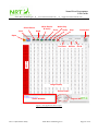
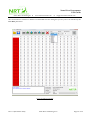
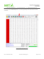
Nano River Programmer User Guide Nano River Technologies www.nanorivertech.com[email protected] 4. PC Application Instructions This section provides an overview of the NR Programmer application program. Figure 3 shows the various windows, displays, progress bars, buttons and drop downs when in a normal user scenario. Image Display The window displays 512 bytes of current image buffer. Values are in hexadecimal. Address To the left of the image display is the address of the left-most byte of data. Device Detail This lists details about the current device type which is selected. Status Window Is a text box showing the status of current commands. Progress Bar Is a status bar indicating the percentage complete of the current task. Open This is selection that lets you select an Intel HEX file to be loaded to the image buffer. Save This selection saves the current image buffer as Intel HEX file. Select Device Selects the device type to be worked with. Read This selection reads the connected device to the image buffer. Write Device & Verify This selection writes and then verifies one or more connected chips. Erase This selection erases one or more connected chips. Write only This function programs one or more connected chips without verification. Verify This function reads one or more connected chips and compares them with the current image buffer. Stop This is used to stop the current operation. Line Rate The default line rate is set by the device type selected but this pulldown lets you over-ride it. Devices This lets you specify which chips are connected to the programmer pod. I2C ID For I2C based devices; this lets you change the I2C device ID. Connected This tells the user if the programmer is connected to the PC. Rev: 0.1 (December 2012) Nano River Technologies © Page 15 of 36