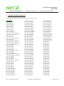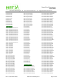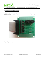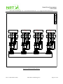
1
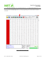
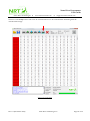
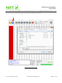
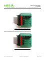
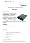
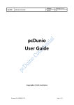
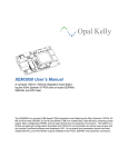
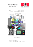
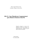
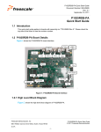
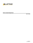
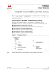
Nano River Programmer User Guide Nano River Technologies www.nanorivertech.com[email protected] Nano River Programmer User Guide Nano River Technologies December 2012 Rev: 0.1 (December 2012) Nano River Technologies © Page 1 of 36 Nano River Programmer User Guide Nano River Technologies www.nanorivertech.com[email protected] Table of Contents 1. OVERVIEW ................................................................................................................... 4 2. PRODUCT SUMMARY ................................................................................................. 5 3. INSTALLATION INSTRUCTIONS (FOR VISTA, WINDOWS 7 AND WINDOWS 8) ...... 7 4. PC APPLICATION INSTRUCTIONS ........................................................................... 15 5. TECHNICAL SUPPORT.............................................................................................. 28 6. APPENDIX A: SUPPORTED DEVICES ...................................................................... 29 7. APPENDIX B: CONNECTOR DETAILS (40-PIN RIBBON)......................................... 33 8. APPENDIX C: SOCKET BOARD ACCESSORY......................................................... 34 Rev: 0.1 (December 2012) Nano River Technologies © Page 2 of 36 Nano River Programmer User Guide Nano River Technologies www.nanorivertech.com[email protected] ABBREVIATIONS API DIP I2C NR Programmer NRT SOIC SPI USB Rev: 0.1 (December 2012) Application Programming Interface Dual Inline Package Inter-Integrated Circuit Interface Nano River Programmer Nano River Technologies ApS Small Outline IC package Serial Peripheral Interface Universal Serial Bus Nano River Technologies © Page 3 of 36 Nano River Programmer User Guide Nano River Technologies www.nanorivertech.com[email protected] 1. Overview Congratulations on the purchase of the Nano River Programmer! We hope that you programmer will be a valuable tool for you for your development or electronics production needs. The Nano River Programmer (or NR Programmer for short) is a commercial ganged programmer for serial non-volatile memories. This manual provides all necessary information for you to get up and running with the programmer. Chapter 2 gives an overview of the product and features. Chapter 3 provides installation instructions including how to install the driver and PC application. Chapter 4 provides in depth details about using the PC application. Chapter 5 provides links to where one can get further information or help about the programmer. Appendix A provides a list of the devices which may be programmed with NR Programmer Appendix B provides connector information and pin-out Appendix C provides details about our socket-board accessory to help program standard packages Rev: 0.1 (December 2012) Nano River Technologies © Page 4 of 36 Nano River Programmer User Guide Nano River Technologies www.nanorivertech.com[email protected] 2. Product Summary The NR Programmer has the following key features: support for I2C EEPROMs support for SPI EEPROMs support for SPI flash memory supports over 6000 devices and packages programs 4 devices at a one time simple intuitive PC application running under Windows XP, Vista, Windows 7, and Windows 8 (MacOS and Linux supported in the future) Figure 1: NR Programmer Programming Pod The NR Programmer consists of a programming pod and a Micro-USB cable. The programming pod connects to the host PC using the uUSB cable. The programming pod connects to non volatile memory via a 40 pin ribbon cable connector provided by the customer. The NR programmer pod also includes two LEDs. One illuminates when there is power to the programmer pod. The second flashes when there is communication with the non volatile memory. Rev: 0.1 (December 2012) Nano River Technologies © Page 5 of 36 Nano River Programmer User Guide Nano River Technologies www.nanorivertech.com[email protected] The standard NR Programmer includes the following items: One programming pod (with Micro USB and 40 pin ribbon connector) One uUSB cable for connection to the host PC Figure 2: Micro-USB Cable Rev: 0.1 (December 2012) Nano River Technologies © Page 6 of 36 Nano River Programmer User Guide Nano River Technologies www.nanorivertech.com[email protected] 3. Installation Instructions (for Vista, Windows 7 and Windows 8) Step 1: Open the Windows Device Manager and remove all previous drivers for NR Programmer. This is of course not needed if you have not installed NR Programmer before. Old versions may be located as a libusb-win32 device. Step 2: Copy the latest device driver binary package (libusb-win32-bin-1.2.5.0.zip) from our Web page. Step 3: Extract it to a temporary directory. Step 4: Connect your NR Programmer. Rev: 0.1 (December 2012) Nano River Technologies © Page 7 of 36 Nano River Programmer User Guide Nano River Technologies www.nanorivertech.com[email protected] Step 5: Navigate to the bin/ directory and then run the INF-Wizard program to generate the INF file. To do this you will see other devices including NR Programmer. You should see the NR Programmer is VID=2058 and PID=1101. Select NR Programmer and then you need to enter the Manufacturer as "Nano River Technologies". Rev: 0.1 (December 2012) Nano River Technologies © Page 8 of 36 Nano River Programmer User Guide Nano River Technologies www.nanorivertech.com[email protected] Step 6: From within the INF-Wizard there is an option to install. Please click this to install. Rev: 0.1 (December 2012) Nano River Technologies © Page 9 of 36 Nano River Programmer User Guide Nano River Technologies www.nanorivertech.com[email protected] Step 8: It will warn about the publisher of the software but choose install anyway. So eventually the driver is installed and complete. Rev: 0.1 (December 2012) Nano River Technologies © Page 10 of 36 Nano River Programmer User Guide Nano River Technologies www.nanorivertech.com[email protected] Step 9: Next you will need to install the NR Programmer application. Just choose the default settings. Rev: 0.1 (December 2012) Nano River Technologies © Page 11 of 36 Nano River Programmer User Guide Nano River Technologies www.nanorivertech.com[email protected] Rev: 0.1 (December 2012) Nano River Technologies © Page 12 of 36 Nano River Programmer User Guide Nano River Technologies www.nanorivertech.com[email protected] Rev: 0.1 (December 2012) Nano River Technologies © Page 13 of 36 Nano River Programmer User Guide Nano River Technologies www.nanorivertech.com[email protected] Step 10: You will then be complete and able to connect your board and run the application from the Windows Start Menu. Rev: 0.1 (December 2012) Nano River Technologies © Page 14 of 36 Nano River Programmer User Guide Nano River Technologies www.nanorivertech.com[email protected] 4. PC Application Instructions This section provides an overview of the NR Programmer application program. Figure 3 shows the various windows, displays, progress bars, buttons and drop downs when in a normal user scenario. Image Display The window displays 512 bytes of current image buffer. Values are in hexadecimal. Address To the left of the image display is the address of the left-most byte of data. Device Detail This lists details about the current device type which is selected. Status Window Is a text box showing the status of current commands. Progress Bar Is a status bar indicating the percentage complete of the current task. Open This is selection that lets you select an Intel HEX file to be loaded to the image buffer. Save This selection saves the current image buffer as Intel HEX file. Select Device Selects the device type to be worked with. Read This selection reads the connected device to the image buffer. Write Device & Verify This selection writes and then verifies one or more connected chips. Erase This selection erases one or more connected chips. Write only This function programs one or more connected chips without verification. Verify This function reads one or more connected chips and compares them with the current image buffer. Stop This is used to stop the current operation. Line Rate The default line rate is set by the device type selected but this pulldown lets you over-ride it. Devices This lets you specify which chips are connected to the programmer pod. I2C ID For I2C based devices; this lets you change the I2C device ID. Connected This tells the user if the programmer is connected to the PC. Rev: 0.1 (December 2012) Nano River Technologies © Page 15 of 36 Nano River Programmer User Guide Nano River Technologies www.nanorivertech.com[email protected] Select Device Save Read Write Only Write Device & Verify Erase Verify Stop Connected Open Devices I2C ID Address Line Rate Image Display Device Detail Status Window Progress Bar Figure 3: PC Application Basic Layout Rev: 0.1 (December 2012) Nano River Technologies © Page 16 of 36 Nano River Programmer User Guide Nano River Technologies www.nanorivertech.com[email protected] By selecting the Select Device icon one can scroll down a list of currently available memory devices and select the memory you would like to program. Figure 4: Select a Device Rev: 0.1 (December 2012) Nano River Technologies © Page 17 of 36 Nano River Programmer User Guide Nano River Technologies www.nanorivertech.com[email protected] The selected device will have a default recommended line rate setting but you may also over-ride this by the Line Rate pull-down. Figure 5: Change Line Rate Rev: 0.1 (December 2012) Nano River Technologies © Page 18 of 36 Nano River Programmer User Guide Nano River Technologies www.nanorivertech.com[email protected] NR Programmer can program up to 4 devices at one time. One may specify which devices are connected to the device with the Devices pull-down. Figure 6: Change Device Rev: 0.1 (December 2012) Nano River Technologies © Page 19 of 36 Nano River Programmer User Guide Nano River Technologies www.nanorivertech.com[email protected] For I2C based devices one may also over-ride the I2C device ID using the I2C ID textbox. Figure 7: Change the I2C Address Rev: 0.1 (December 2012) Nano River Technologies © Page 20 of 36 Nano River Programmer User Guide Nano River Technologies www.nanorivertech.com[email protected] To read a device, select the Read button. For ganged usage only the last device is displayed in the image display. Figure 8: Read a Device Rev: 0.1 (December 2012) Nano River Technologies © Page 21 of 36 Nano River Programmer User Guide Nano River Technologies www.nanorivertech.com[email protected] To erase a device, select the Erase button. For ganged usage then all connected chips are erased. Figure 9: Erase a Device Rev: 0.1 (December 2012) Nano River Technologies © Page 22 of 36 Nano River Programmer User Guide Nano River Technologies www.nanorivertech.com[email protected] One can open an Intel HEX file and load this into the image buffer using the Open file button. Figure 10: Open a File Rev: 0.1 (December 2012) Nano River Technologies © Page 23 of 36 Nano River Programmer User Guide Nano River Technologies www.nanorivertech.com[email protected] You can write the current image and then verify for all connected devices using the Write Device and Verify button. Status is provided in the status window. Figure 11: Write Device and Verify Rev: 0.1 (December 2012) Nano River Technologies © Page 24 of 36 Nano River Programmer User Guide Nano River Technologies www.nanorivertech.com[email protected] You may also select the Write Only button is you want programming of the connected devices without verification. Figure 12: Write Only and Not Verify Rev: 0.1 (December 2012) Nano River Technologies © Page 25 of 36 Nano River Programmer User Guide Nano River Technologies www.nanorivertech.com[email protected] Selection of the Verify button will cause all connected devices to be read and then checked against the current buffer image. Figure 13: Verify Only Rev: 0.1 (December 2012) Nano River Technologies © Page 26 of 36 Nano River Programmer User Guide Nano River Technologies www.nanorivertech.com[email protected] One can save the current buffer image to Intel HEX file using the Save button. Figure 14: Save Image to a File Rev: 0.1 (December 2012) Nano River Technologies © Page 27 of 36 Nano River Programmer User Guide Nano River Technologies www.nanorivertech.com[email protected] 5. Technical Support Technical information regarding the programmer can be found on our web-site (www.nanorivertech.com). The NR Programmer application will be continually improved to support the latest non-volatile memories and to fix any issues found in programming supported devices. If you find devices not supported or issues with existing devices then please send a technical enquiry to: [email protected] Rev: 0.1 (December 2012) Nano River Technologies © Page 28 of 36 Nano River Programmer User Guide Nano River Technologies www.nanorivertech.com[email protected] 6. Appendix A: Supported Devices NR Programmer supports the following devices in all package variants. I2C EEPROM Atmel AT24C01B Atmel AT24C02B Atmel AT24C04B Atmel AT24C08B Atmel AT24C01C Atmel AT24C02C Atmel AT24C04C Atmel AT24C08C Atmel AT24C1024B Atmel AT24C128 Automotive Atmel AT24C256 Automotive Atmel AT24C128C Atmel AT24C16C Atmel AT24C16C Automotive Atmel AT24C256C Atmel AT24C32A Automotive Atmel AT24C64A Automotive Atmel AT24C32D Automotive Atmel AT24C64D Automotive Atmel AT24C32D Atmel AT24C64D Atmel AT24C512C Atmel AT24C64B Atmel AT24C64B Automotive Atmel AT24CM01 Atmel AT24HC02B Atmel AT24HC02B Automotive Atmel AT24HC04B Automotive Atmel AT24HC02C Atmel AT24HC04B Atmel AT34C02C Atmel AT34C02C Automotive Atmel AT34C02D Microchip 24AA00 Microchip 24C00 Microchip 24LC00 Microchip 24AA01 Microchip 24AA014 Microchip 24AA014H Microchip 24AA01H Microchip 24LC014 Microchip 24LC014H Microchip 24LC01B Microchip 24LC01BH Rev: 0.1 (December 2012) Microchip 24LC21A Microchip 24LCS21A Microchip 24VL014 Microchip 24VL014H Microchip 24AA02 Microchip 24AA024 Microchip 24AA024H Microchip 24AA025 Microchip 24AA025E48 Microchip 24AA02E48 Microchip 24AA02H Microchip 24LC024 Microchip 24LC024H Microchip 24LC025 Microchip 24LC02B Microchip 24LC02BH Microchip 24LC22A Microchip 24LCS22A Microchip 24VL024 Microchip 24VL024H Microchip 24VL025 Microchip 24AA04 Microchip 24AA04H Microchip 24LC04B Microchip 24LC04BH Microchip 24AA08 Microchip 24AA08H Microchip 24LC08B Microchip 24LC08BH Microchip 24AA16 Microchip 24AA16H Microchip 24LC16B Microchip 24LC16BH Microchip 24AA32A Microchip 24AA32AF Microchip 24LC32A Microchip 24LC32AF Microchip 24AA64 Microchip 24AA64F Microchip 24AA65 Microchip 24FC64 Microchip 24LC64 Microchip 24LC64F Microchip 24LC65 Microchip 24AA128 Nano River Technologies © Microchip 24FC128 Microchip 24LC128 Microchip 24AA256 Microchip 24FC256 Microchip 24LC256 Microchip 24AA512 Microchip 24AA515 Microchip 24FC512 Microchip 24FC515 Microchip 24LC512 Microchip 24LC515 Microchip 24AA1025 Microchip 24AA1026 Microchip 24FC1025 Microchip 24FC1026 Microchip 24LC1025 Microchip 24LC1026 ST M24C01-W ST M24C01-R ST M24C02-W ST M24C02-R ST M24C04-W ST M24C04-R ST M24C04-F ST M24C08-W ST M24C08-R ST M24C08-F ST M24C016-W ST M24C016-R ST M24C016-F ST M24C32-DF ST M24C32-F ST M24C32-R ST M24C32-W ST M24C32-X ST M24C64-DF ST M24C64-F ST M24C64-R ST M24C64-W ST M24128-BF ST M24128-BR ST M24128-BW ST M24128-DF ST M24256-BF ST M24256-BR Page 29 of 36 Nano River Programmer User Guide Nano River Technologies www.nanorivertech.com[email protected] ST M24256-BW ST M24256-DR ST M24256-DF ST M24512-DF ST M24512-DR ST M24512-R ST M24512-W ST M24M01-R ST M24M01-DF ST M24M02-DR SPI EEPROMs Atmel AT25010B Automotive Atmel AT25020B Automotive Atmel AT25040B Automotive Atmel AT25080A Automotive Atmel AT25160A Automotive Atmel AT25320B Automotive Atmel AT25640B Automotive Atmel AT25080B Automotive Atmel AT25160B Automotive Atmel AT25320B Automotive Atmel AT25640B Automotive Atmel AT25128B Automotive Atmel AT25256B Automotive Atmel AT25010B Atmel AT25020B Atmel AT25040B Atmel AT25080B Atmel AT25160B Atmel AT25320B Atmel AT25640B Atmel AT25128B Atmel AT25256B Atmel AT25512 Microchip 25AA010A Microchip 25LC010A Microchip 25AA020A Microchip 25AA02E48 Microchip 25LC020A Microchip 25AA040A Microchip 25LC040A Microchip 25AA080C Microchip 25AA080D Microchip 25LC080C Microchip 25LC080D Microchip 25AA160C Microchip 25AA160D Microchip 25LC160C Microchip 25LC160D Microchip 25AA320A Rev: 0.1 (December 2012) Microchip 25LC320A Microchip 25AA640A Microchip 25LC640A Microchip 25AA128 Microchip 25LC128 Microchip 25AA256 Microchip 25LC256 Microchip 25AA512 Microchip 25LC512 Microchip 25AA1024 Microchip 25LC1024 ST M95010-R ST M95010-W ST M95020-R ST M95020-W ST M95040-W ST M95040-R ST M95080-R ST M95080-W ST M95160-F ST M95160-R ST M95160-W ST M95320-DR ST M95320-W ST M95320-R ST M95640-DR ST M95640-R ST M95640-W ST M95128-W ST M95128-R ST M95128-DF ST M95256-DR ST M95256-DF ST M95256-W ST M95256-R ST M95512-R ST M95512-DR ST M95512-DF ST M95512-W ST M95M01-DF ST M95M01-R ST M95M02-DR SPI Flash Memory Micron M25P20-VMP6G Micron M25P20-VMP6GB Micron M25P20-VMP6TG Micron M25P20-VMP6TGB Micron M25PE20-V6D11 Micron M25PE20-VMN6P Micron M25PE20-VMN6TP Nano River Technologies © Micron M25PE20-VMN6TPBA Micron M25PE20-VMP6G Micron M25PE20-VMP6TG Micron M25PE20-VMW6G Micron M25PE20-VMW6TG Micron M45PE20-VMN6P Micron M45PE20-VMN6TP Micron M45PE20-VMP6G Micron M45PE20-VMP6TG Micron M25P40-VMB3TPB Micron M25P40-VMB6TPB Micron M25P40-VMC6G Micron M25P40-VMC6GB Micron M25P40-VMC6TG Micron M25P40-VMC6TGB Micron M25P40-VMN3PB Micron M25P40-VMN3TPB Micron M25P40-VMN6P Micron M25P40-VMN6PB Micron M25P40-VMN6PBA Micron M25P40-VMN6TP Micron M25P40-VMN6TPB Micron M25P40-VMN6TPBA Micron M25P40-VMP6G Micron M25P40-VMP6GB Micron M25P40-VMP6TGB Micron M25P40-VMW6G Micron M25P40-VMW6GB Micron M25P40-VMW6TG Micron M25P40-VMW6TGB Micron M25PE40S-VMN6P Micron M25PE40S-VMN6TP Micron M25PE40-VMC6G Micron M25PE40-VMC6TG Micron M25PE40-VMN6P Micron M25PE40-VMN6TP Micron M25PE40-VMN6TPBA Micron M25PE40-VMP6G Micron M25PE40-VMP6TG Micron M25PE40-VMW6G Micron M25PE40-VMW6TG Micron M45PE40S-VMN6P Micron M45PE40S-VMN6TP Micron M45PE40-VMN6P Micron M45PE40-VMN6TP Micron M45PE40-VMP6G Micron M45PE40-VMP6TG Micron M45PE40-VMW6G Micron M45PE40-VMW6TG Micron M25P80S-VMN6P Micron M25P80S-VMN6TP Page 30 of 36 Nano River Programmer User Guide Nano River Technologies www.nanorivertech.com[email protected] Micron M25P80-VMC6G Micron M25P80-VMC6TG Micron M25P80-VMN3PB Micron M25P80-VMN3TPB Micron M25P80-VMN6P Micron M25P80-VMN6PBA Micron M25P80-VMN6TP Micron M25P80-VMN6TPBA Micron M25P80-VMP6G Micron M25P80-VMP6TG Micron M25P80-VMW6G Micron M25P80-VMW6TG Micron M25PE80-VMN6P Micron M25PE80-VMN6TP Micron M25PE80-VMN6TPBA Micron M25PE80-VMP6G Micron M25PE80-VMP6TG Micron M25PE80-VMW6G Micron M25PE80-VMW6TG Micron M25PX80-VBA6P Micron M25PX80-VMN6P Micron M25PX80-VMN6TP Micron M25PX80-VMN6TPBA Micron M25PX80-VMP6G Micron M25PX80-VMP6TG Micron M25PX80-VMW6G Micron M25PX80-VMW6TG Micron M25PX80-VZM6P Micron M25PX80-VZM6TP Micron M45PE80-VMN6P Micron M45PE80-VMN6TP Micron M45PE80-VMP6G Micron M45PE80-VMP6TG Micron M45PE80-VMW6G Micron M45PE80-VMW6TG Micron M25P16S-VMN6P Micron M25P16S-VMN6TP Micron M25P16-V6D11 Micron M25P16-VMC6G Micron M25P16-VMC6TG Micron M25P16-VME6G Micron M25P16-VME6TG Micron M25P16-VMF3PB Micron M25P16-VMF3TPB Micron M25P16-VMF6P Micron M25P16-VMF6PBA Micron M25P16-VMF6TP Micron M25P16-VMN3PB Micron M25P16-VMN3TPB Micron M25P16-VMN3YPB Micron M25P16-VMN6P Rev: 0.1 (December 2012) Micron M25P16-VMN6PBA Micron M25P16-VMN6TP Micron M25P16-VMN6TPBA Micron M25P16-VMN6YPBA Micron M25P16-VMP6G Micron M25P16-VMP6TG Micron M25P16-VMW6G Micron M25P16-VMW6TG Micron M25P16-VMW6YG Micron M25PE16-VMP6G Micron M25PE16-VMP6TG Micron M25PE16-VMW6G Micron M25PE16-VMW6TG Micron M25PX16SOVMN6P Micron M25PX16SOVMN6TP Micron M25PX16SOVZM6TP Micron M25PX16STVZM6TP Micron M25PX16-VD11 Micron M25PX16-VMN6P Micron M25PX16-VMN6TP Micron M25PX16-VMN6TPBA Micron M25PX16-VMP6G Micron M25PX16-VMP6TG Micron M25PX16-VMW6G Micron M25PX16-VMW6TG Micron M25PX16-VZM6P Micron M25PX16-VZM6TP Micron M45PE16-VMP6G Micron M45PE16-VMP6TG Micron M45PE16-VMW6G Micron M45PE16-VMW6TG Micron M25P32-VME6G Micron M25P32-VME6TG Micron M25P32-VMF3TPB Micron M25P32-VMF6P Micron M25P32-VMF6PBA Micron M25P32-VMF6TP Micron M25P32-VMP6G Micron M25P32-VMP6TG Micron M25P32-VMW3TGB Micron M25P32-VMW6G Micron M25P32-VMW6GBA Micron M25P32-VMW6TG Micron M25P32-VMW6TGBA Micron M25PX32SOVZM6E Micron M25PX32-VMF6E Micron M25PX32-VMF6F Micron M25PX32-VMP6E Micron M25PX32-VMP6F Micron M25PX32-VMP6FBA Micron M25PX32-VMW6E Nano River Technologies © Micron M25PX32-VMW6F Micron M25PX32-VZM6E Micron M25PX32-VZM6F Micron M25PX32-VZM6FBA Micron N25Q032A13E1240E Micron N25Q032A13E1240F Micron N25Q032A13E1241E Micron N25Q032A13E1241F Micron N25Q032A13EF440E Micron N25Q032A13EF440F Micron N25Q032A13EF640E Micron N25Q032A13EF640F Micron N25Q032A13EF840E Micron N25Q032A13EF840F Micron N25Q032A13ESC40F Micron N25Q032A13ESC40G Micron N25Q032A13ESCA0F Micron N25Q032A13ESE40F Micron N25Q032A13ESE40G Micron N25Q032A13ESF40F Micron N25Q032A13ESF40G Micron N25Q032A13ESFA0F Micron N25Q032A13ESFH0F Micron M25P64S-VMF6P Micron M25P64S-VMF6TP Micron M25P64-VME6G Micron M25P64-VME6TG Micron M25P64-VMF3PB Micron M25P64-VMF3TPB Micron M25P64-VMF6PBA Micron M25P64-VMF6TP Micron M25P64-VMF6TPBA Micron M25PX64-VME6G Micron M25PX64-VME6TG Micron M25PX64-VMF6P Micron M25PX64-VMF6TP Micron M25PX64-VZM6P Micron M25PX64-VZM6TP Micron N25Q064A13E1240E Micron N25Q064A13E1240F Micron N25Q064A13E1241E Micron N25Q064A13E1241F Micron N25Q064A13EF640E Micron N25Q064A13EF640F Micron N25Q064A13EF840E Micron N25Q064A13EF840F Micron N25Q064A13EF8A0F Micron N25Q064A13EF8H0F Micron N25Q064A13ESE40F Micron N25Q064A13ESE40G Micron N25Q064A13ESEH0F Page 31 of 36 Nano River Programmer User Guide Nano River Technologies www.nanorivertech.com[email protected] Micron N25Q064A13ESF40F Micron N25Q064A13ESF40G Micron N25Q064A13ESFA0F Micron N25Q064A13ESFH0F Micron M25P128-VME6GB Micron M25P128-VME6TGB Micron M25P128-VMF6PB Micron M25P128-VMF6TPB Micron N25Q128A13B1240E Micron N25Q128A13B1240F Micron N25Q128A13BF840E Micron N25Q128A13BF840F Micron N25Q128A13BSF40F Micron N25Q128A13BSF40G Micron N25Q128A13BSFH0F Micron N25Q128A13E1240E Micron N25Q128A13E1240F Micron N25Q128A13E1241E Micron N25Q128A13E1241F Micron N25Q128A13EF740F Micron N25Q128A13EF840E Micron N25Q128A13EF840F Micron N25Q128A13EF8A0F Micron N25Q128A13ESE40E Micron N25Q128A13ESE40F Micron N25Q128A13ESE40G Micron N25Q128A13ESF40E Micron N25Q128A13ESF40F Micron N25Q128A13ESF40G Micron N25Q128A13ESFA0F Micron N25Q128A13ESFH0F Micron N25Q256A13E1240E Micron N25Q256A13E1240F Micron N25Q256A13E1241E Micron N25Q256A13E1241F Micron N25Q256A13EF840E Micron N25Q256A13EF840F Micron N25Q256A13ESF40F Micron N25Q256A13ESF40G Micron N25Q256A13ESFA0F Micron N25Q256A13ESFH0F Micron N25Q256A33E1241E Micron N25Q256A33E1241F Micron N25Q256A73ESF40F Micron N25Q256A73ESF40G Micron N25Q256A83E1240E Micron N25Q256A83E1240F Micron N25Q256A83E1241E Micron N25Q256A83E1241F Micron N25Q256A83ESF40F Micron N25Q256A83ESF40G Rev: 0.1 (December 2012) Micron N25Q512A13G1240E Micron N25Q512A13G1240F Micron N25Q512A13G1241E Micron N25Q512A13G1241F Micron N25Q512A13GF840E Micron N25Q512A13GF840F Micron N25Q512A13GSF40F Micron N25Q512A13GSF40G Micron N25Q512A83G1240E Micron N25Q512A83G1240F Micron N25Q512A83G1241E Micron N25Q512A83G1241F Micron N25Q512A83GSF40F Micron N25Q512A83GSF40G Micron N25Q00AA13G1240E Micron N25Q00AA13G1240F Micron N25Q00AA13GSF40F Micron N25Q00AA13GSF40G Atmel AT25DF041A Atmel AT25DF081A Atmel AT25DF321A Atmel AT25DF641 Atmel AT25DF641A Atmel AT25DQ321 Atmel AT25F512B Atmel AT45DB011D Atmel AT45DB021D Atmel AT45DB021E Atmel AT45DB041D Atmel AT45DB081D Atmel AT45DB161D Atmel AT45DB161E Atmel AT45DB321D Atmel AT45DB321E Atmel AT45DB642D Atmel AT45BR3214B Atmel AT45CS1282 Atmel AT45DB011 Atmel AT45DB011B Nano River Technologies © Page 32 of 36 Nano River Programmer User Guide Nano River Technologies www.nanorivertech.com[email protected] 7. Appendix B: Connector Details (40-pin ribbon) The following table shows the pin out for the 40 pin ribbon cable connector on the NR programmer pod. Pin Name Channel #4 1 0V 2 5V 3 I2C_SCL_4 4 I2C_SDA_4 5 SPI_DI_4 6 SPI_DO_4 7 SPI_SCK_4 8 SPI_CSN_4 9 0V 10 3.3V Channel #3 11 0V 12 5V 13 I2C_SCL_3 14 I2C_SDA_3 15 SPI_DI_3 16 SPI_DO_3 17 SPI_SCK_3 18 SPI_CSN_3 19 0V 20 3.3V Channel #2 21 0V 22 5V 23 I2C_SCL_2 24 I2C_SDA_2 25 SPI_DI_2 26 SPI_DO_2 27 SPI_SCK_2 28 SPI_CSN_2 29 0V 30 3.3V Channel #1 31 0V 32 5V 33 I2C_SCL_1 34 I2C_SDA_1 35 SPI_DI_1 36 SPI_DO_1 37 SPI_SCK_1 38 SPI_CSN_1 39 0V 40 3.3V Rev: 0.1 (December 2012) Direction Level Description Power Power OUT IN/OUT IN OUT OUT OUT Power Power 0V 5V 3.3V or 5V 3.3V or 5V 3.3V or 5V 3.3V or 5V 3.3V or 5V 3.3V or 5V 0V 3.3V Ground Connection Power from NR Programmer I2C clock signal out from NR Programmer (channel #4) I2C data signal in/out to/from NR Programmer (channel #4) SPI data signal in to NR Programmer (channel #4) SPI data signal out from NR Programmer (channel #4) SPI clock signal out from NR Programmer (channel #4) SPI chip select signal out from NR Programmer (channel #4) Ground Connection Power from NR Programmer Power Power OUT IN/OUT IN OUT OUT OUT Power Power 0V 5V 3.3V or 5V 3.3V or 5V 3.3V or 5V 3.3V or 5V 3.3V or 5V 3.3V or 5V 0V 3.3V Ground Connection Power from NR Programmer I2C clock signal out from NR Programmer (channel #3) I2C data signal in/out to/from NR Programmer (channel #3) SPI data signal in to NR Programmer (channel #3) SPI data signal out from NR Programmer (channel #3) SPI clock signal out from NR Programmer (channel #3) SPI chip select signal out from NR Programmer (channel #3) Ground Connection Power from NR Programmer Power Power OUT IN/OUT IN OUT OUT OUT Power Power 0V 5V 3.3V or 5V 3.3V or 5V 3.3V or 5V 3.3V or 5V 3.3V or 5V 3.3V or 5V 0V 3.3V Ground Connection Power from NR Programmer I2C clock signal out from NR Programmer (channel #2) I2C data signal in/out to/from NR Programmer (channel #2) SPI data signal in to NR Programmer (channel #2) SPI data signal out from NR Programmer (channel #2) SPI clock signal out from NR Programmer (channel #2) SPI chip select signal out from NR Programmer (channel #2) Ground Connection Power from NR Programmer Power Power OUT IN/OUT IN OUT OUT OUT Power Power 0V 5V 3.3V or 5V 3.3V or 5V 3.3V or 5V 3.3V or 5V 3.3V or 5V 3.3V or 5V 0V 3.3V Ground Connection Power from NR Programmer I2C clock signal out from NR Programmer (channel #1) I2C data signal in/out to/from NR Programmer (channel #1) SPI data signal in to NR Programmer (channel #1) SPI data signal out from NR Programmer (channel #1) SPI clock signal out from NR Programmer (channel #1) SPI chip select signal out from NR Programmer (channel #1) Ground Connection Power from NR Programmer Nano River Technologies © Page 33 of 36 Nano River Programmer User Guide Nano River Technologies www.nanorivertech.com[email protected] 8. Appendix C: Socket Board Accessory For programming of common packaged memories in DIP or SOIC then one can purchase the NR Socket Board accessory. The board plugs directly into the NR Programmer and allows programming of 4 NV memories at one time. Figure 15: NR Socket Board Figure 16 provides the schematic for this. The board is fitted with low insertion force sockets for batch programming of memory devices. Rev: 0.1 (December 2012) Nano River Technologies © Page 34 of 36 X1 Rev: 0.1 (December 2012) Nano River Technologies © 0V 5.0V I2C_SCL_4 I2C_SDA_4 SPI_DI_4 SPI_DO_4 SPI_SCK_4 SPI_CSN_4 0V 3.3V 0V 5.0V I2C_SCL_3 I2C_SDA_3 SPI_DI_3 SPI_DO_3 SPI_SCK_3 SPI_CSN_3 0V 3.3V 0V 5.0V I2C_SCL_2 I2C_SDA_2 SPI_DI_2 SPI_DO_2 SPI_SCK_2 SPI_CSN_2 0V 3.3V 0V 5.0V I2C_SCL_1 I2C_SDA_1 SPI_DI_1 SPI_DO_1 SPI_SCK_1 SPI_CSN_1 0V 3.3V 1 2 3 4 5 6 7 8 9 10 11 12 13 14 15 16 17 18 19 20 21 22 23 24 25 26 27 28 29 30 31 32 33 34 35 36 37 38 39 40 5V 3.3V 5V 3.3V 5V 3.3V 5V 3.3V J1-X J1-W J1-V J1-U J1-T J1-S 3.3V J1-R J1-Q J1-P J1-O J1-N J1-M 3.3V J1-L J1-K J1-J J1-I J1-H J1-G 3.3V J1-F J1-E J1-D J1-C J1-B J1-A 3.3V J1 C7 100n C5 100n C3 100n C1 100n 3.3V 3.3V 3.3V 3.3V 8 7 6 5 4 3 2 1 8 7 6 5 4 3 2 1 8 7 6 5 4 3 2 1 8 7 6 5 4 3 2 1 DIP Socket U7 DIP Socket U5 DIP Socket U3 DIP Socket U1 C8 100n C6 100n C4 100n C2 100n 3.3V 3.3V 3.3V 3.3V 8 7 6 5 4 3 2 1 8 7 6 5 4 3 2 1 8 7 6 5 4 3 2 1 8 7 6 5 4 3 2 1 N tte Fi ot SOIC Socket U8 N d d d tte Fi ot SOIC Socket U6 N tte Fi ot SOIC Socket U4 SOIC Socket U2 A3 Title Sheet Socket Board Rev 1 of 1 Nano River Technologies 11. November 2012 Date Size 1.0 Nano River Programmer User Guide Nano River Technologies www.nanorivertech.com[email protected] Figure 16: NR Socket Board Schematic Page 35 of 36 Nano River Programmer User Guide Nano River Technologies www.nanorivertech.com[email protected] When programming I2C devices jumpers should be placed as shown in figure 17. Figure 17: Jumpers when programming I2C devices When programming SPI devices jumpers should be placed as shown in figure 18. Figure 18: Jumpers when programming SPI devices Rev: 0.1 (December 2012) Nano River Technologies © Page 36 of 36