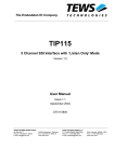
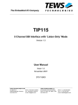
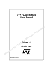
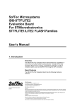
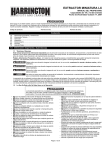
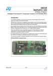
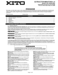
1
Evaluation board for
microcontrollers ST7LITE and ST72F26x.
User
Manual
REV 1.0
,
lu ard ST Sta rve
a
e
,
o
Ev B VR ers b S d
l
n
io 1, A trol We mo
t
i
a ‘5
in ron ed
r
c
fo cro dd s M the
e
s
d e
i
m mb oar rs, peC E B e S
PI its ng roll gh r
K pi nt Hi fo
r
y
o
rte tot roc FID ers s
o c
r
Pr mi s, R mm lle
rs or ler gra tro
f ol
n
o
s
pr oco CB
e ntr
l
u o
m icr s, P for
c
e
t
t
m m ds
s
e
ne Sy T
st oar lS
n
y
I
,
s B tro
C
d
I
r
e P
o tion con eb
s
,
R ce lua cro W
V
A pro va mi ed iro g E IC edd m
c
i
s
M nin T, P mb rd ,
a s
g
si , S its E Bo ller
e
d VR K ng ro
A ter pi
nt igh
,
y
o
r
t
1
H
‘5 Sta oto roc ID c
r
e
rs P mi RF m
e
s
l
,
r
er fo ers ram trlv
g n
r
s
ll
Se ule tro pro oco
od con ms icr s,
m
ni net ste T m stem
er Sy , S sy Bo
h
et d In PIC sor on e
, ce ati
ic
e
R
m
o
u
Sp AV opr val IC e
r r
fo ic g E T, P mb
rs s M nin , S
E g
s
r
t
g
R
i
i
in
le
ol des , AV er K typ
B `51 tart roto roS s P mic ,
PC for
s
s ller er for lers
d
l
ar tro erw les tro on b S du con ram
c
ro We imo et rog p co
d in ern
e
o
M
m
dd ds eth ste icr
ar rs, Sy T m r
o
B olle In , S so
tr ed IC oce ign
P
s
co Spe R, opr De
V cr
h
B Rtion
ig r A Mi
C
a
H f o rs
, Pone asolution
lu
Many ideas
s
e
s
l
v s
m
er ol
m ntr ste g E ard
co Sy nin Bo
1. Introduction
EVBST7-DISK is a development board designed for the hobbyists and
engineers who want easily prototype their system based on ST7LITE and ST72F26x
microcontrollers from STMicroelectronics. This board allows implementing engineer’s
idea without a hitch.
Developer has access to all pins all processors and peripherals devices, which are
connected to the header (pin connectors). There are six sockets for microcontrollers
(which every microcontroller is independent)
and peripheral devices like:
thermometer, relays, potentiometers, eight buttons and eight LED’s, real time clock,
interface RS232, FLASH memory, LED displays and optionally assembled LCD (2 x
16 symbols) on board.
The board contains also a power supply which relieves the user from the need to
provide a regulated supply voltage. This board comes with the several examples of
the C code routines (source form), to facilitate testing and quick development in using
the board’s resources.
We wish great success and full satisfaction while designing and
constructing appliances based on EVBST7-DISK
Features:
- 6 sockets for microcontrollers
- connectors of all peripherals accessible on board
- power supply circuit
- port RS232
- independent programming connectors
- socket for LCD 2x16
- 2 potentiometers
- 8 buttons
- real time clock
- Flash memory
- 8 LEDs
- 4 LED displays
- buzzer
2
2. Board layout
1
1
1
2
2
2
2
1
16
10
9
8
7
6
5
4
3
2
1
15
14
13
12
11
10
9
8
7
6
5
4
3
2
1
10
9
8
7
6
5
4
3
10
9
2
1
8
7
6
5
4
3
2
1
1
10
9
2
17
8
7
18
19
20
21
22
23
24
25
26
27
28
29
30
31
32
2
6
5
4
3
1
2
10
9
8
7
6
5
1
2
2
2
1
1
4
3
2
1
1
1
2
2
1
2
25
23
21
19
17
15
13
11
9
7
5
3
1
26
24
22
20
18
16
14
12
10
8
6
4
2
1
2
1
1
10
9
8
7
6
5
4
3
2
1
1
2
2
2
1
1
2
1
1
8
2
7
9
2
10
6
11
5
12
4
3
13
2
14
1
10
9
8
7
6
5
4
3
2
4
1
3
2
1
10
9
8
7
6
5
4
3
2
8
7
6
5
4
3
2
1
20
9
10
11
12
13
14
15
16
1
2
1
1
1
1
2
2
2
15
16
11
12
13
14
15
16
17
18
19
20
5
6
7
8
11
12
13
14
15
16
17
18
19
1
2
8
7
6
5
4
3
2
1
19
17
15
13
11
9
7
5
3
1
7
5
3
1
10
9
8
7
6
5
4
3
2
1
15
13
11
9
7
5
3
1
16
15
14
13
12
11
10
9
20
18
16
14
12
10
8
6
4
2
8
6
4
2
20
19
18
17
16
15
14
13
12
11
16
14
12
10
8
6
4
2
4
3
2
1
7
5
3
1
11
9
7
5
3
1
7
5
3
1
9
7
5
3
1
5
3
1
5
3
1
5
3
1
11
9
7
5
3
1
2
8
7
6
5
8
6
4
2
12
10
8
6
4
2
8
6
4
2
10
8
6
4
2
6
4
2
6
4
2
6
4
2
12
10
8
6
4
2
1
1
BO1
2
1
6
3
2
7
3
2
8
2
1
2
3
2
3
5
4
5
4
2
3
4
5
6
7
8
9
10
11
12
13
14
15
1
4
16
9
1
5
1
3
2
BO2
3
1
1
1
1
2
1
2
2
1
2
1
2
2
1
0
2
3
1
1
0
2
3
2
0
0
1
1
2
3
1
10
9
8
7
6
10
9
8
7
6
10
9
8
7
6
10
9
8
7
6
1
2
1
2
1
1
2
3
4
5
1
2
3
4
5
1
2
3
4
5
1
2
3
4
5
2
1
3
4
2
1
3
2
1
3
2
3
4
1
3
4
3
1
2
4
3
1
2
2
4
3
4
4
1
3
4
1
2
1
3
1
2
1
3
3
2
1
4
2
2
Fig.1 Component location on EVBST7-DISK
1. Socket for ST7226x microcontroller
2. Socket for ST7LITE1xB microcontroller
3. Socket for ST7LITE3 microcontroller
4. Socket for ST7UltraLite microcontroller
5. Socket for ST7LITE2 microcontroller
6. Socket for ST7LITE0x and ST7SuperLite microcontroller
7. Connector with all terminals of ST7226x
8. Connector with all terminals of ST7LITE1xB
9. Connector with all terminals of ST7LITE3
10. Connector with all terminals of ST7UltraLite
11. Connector with all terminals of ST7LITE2
12. Connector with all terminals of ST7LITE0 i ST7UltraLite
13. Programming connector for ST7LITE1xB
3
14. Programming connector for ST7LITE3
15. Programming connector for ST7UltraLite
16. Programming connector for ST7226x
17. Programming connector for ST7LITE2
18. Programming connector for ST7LITE0 i ST7SuperLite
19. Quartz crystal and jumpers for ST7LITE1xB
20. Quartz crystal and jumpers for ST7LITE3
21. Quartz crystal and jumpers for ST7226x
22. Quartz crystal and jumpers for ST7LITE2
23. Connectors of all peripherals
24. Terminal blocks connected to relays contacts
25. Relays
26. Potentiometer for LCD contrast
27. Battery charging jumpers
28. Connector for LCD 2x16
29. Real Time Clock M41T81
30. 8Mbit Flash memory - M45PE80
31. LM317 voltage regulator
32. RS-232 driver / receiver (ST3232)
33. RS-232 port
34. Power supply connector
35. Power switch
36. Buzzer
37. Battery 3,6V 65mAh
38. LED displays
39. RESET button
40. Potentiometers
41. Eight LEDs
42. Thermometer LM35
43. Eight buttons
3. Supported microcontrollers
EVBST7-DISK has been prepared for microcontrollers:
- ST7226x (SDIP-32)
- ST7LITE3 (DIP-20)
- ST7LITE2 (DIP-20)
- ST7LITE1xB (DIP-16)
- ST7LITE0 (DIP-16)
- ST7SuperLite (DIP-16)
- ST7UltraLite (DIP-8)
4. Board power supply
Recommended external power supply voltage is 7-12V AC, or 9-15V DC. A
standard power jack (bolt diameter 2.1mm) is provided at the edge of the board.
Stabilized voltage VDD is available on the double header and on the prototype area
of the board. The selection of the VDD is provided through a 3V3 header. The default
voltage VDD is 5VDC (no jumper on 3V3 header). By placing a jumper Vdd becomes
3.3 VDC.
4
The SUPPLY jumper provides power from voltage regulator to devices and
microcontrollers. Additionally, each microcontroller has one jumper to provide power
supply voltage to microcontroller VDD pin. The jumpers’ names are: PWR ST72,
PWR L3, PWR L2, PWR L1xB, PWR L0/S and PWR UL. These additional jumpers
where implement to give a possibility of current measure or powering MCU from
battery.
5. Microcontrollers circuits
There are six sockets on board for microcontrollers marked on Fig.1 as 1, 2…
6, six programming connector for each MCU and four of them have quartz oscillator.
Every MCU is connected to own header. This construction allows working with more
than one MCU at the same time.
6. Peripheral circuits
6.1. LED’s
The board has 8 LED diodes, which make the simplest interface between the system
and the user. This is especially useful for the beginners. All diode are connected via
resistor to VDD, the diode turns on after grounding of the associated LDn (n = 0 –
8)pin
Vdd
Vdd
R17
1k
Vdd
R18
1k
D0
Vdd
R19
1k
D1
Vdd
R20
1k
1K
D2
Vdd
R21
1k
D3
Vdd
R22
1k
D4
Vdd
R23
1k
D5
R24
1k
D6
JP8
D7
L1
L3
L5
L7
1
3
5
7
2
4
6
8
L2
L4
L6
L8
L8
L7
L6
L5
L4
L3
L2
L1
LED
Fig.2. Implementation of LED’s
6.2. Switches
The board is equipped with 8 push-buttons. Pressing one of them causes
grounding of the corresponding pin on the KEY header.
5
Vdd
Vdd
R29
10k
Vdd
R30
10k
K1
Vdd
R31
10k
K2
S0
Vdd
R32
10k
K3
S1
Vdd
R33
10k
K4
S2
Vdd
R34
10k
R35
10k
K5
S3
Vdd
K6
S4
R36
10k
K7
S5
JP7
K1
K3
K5
K7
K8
S6
S7
1
3
5
7
2
4
6
8
K2
K4
K6
K8
KEY
GND
GND
GND
GND
GND
GND
GND
GND
Fig.3. Implementation of push-buttons
6.3. Relays
The board has two relays driven through transistors, where the base of
transistor is connected to MISC header and marked as RL1 and RL2. The relays
contacts NO, NC, COM, are connected to JP9 and JP11, which allows driving
external device. The relay is switching-on after grounding of the associated pin.
Vdd
Vdd
R1
Q2
BC 857
4k7
R2
REL5
Q3
BC 857
4k7
REL8
1
3
5
REL3
GND
JP9
JP3
TEM
POT2
POT1
RL2
RELAY-SPDT
D9
LL4148
REL2
REL6
GND
REL4
REL7
RL1
RELAY-SPDT
D8
REL1
2
4
6
REL5
REL1
BUZ1
MISC
REL3
REL2
REL4
1
2
3
REL2
JP11
REL7
REL6
REL8
1
2
3
REL1
Fig.4. Implementation of relays
6.4. Buzzer
The board has a built-in acoustic signaler, controlled by a logic low state
through a transistor. The base of the transistor is connected to connector MISC
marked as BUZ.
6
R3
BUZ1
4k7
JP3
SPK1
Vdd
Q1
BC857
TEM
POT2
POT1
1
3
5
2
4
6
REL5
REL1
BUZ1
MISC
GND
BUZ
Fig.5. Connection schematic of buzzer
6.5. Thermometer
The board has one temperature sensor LM35. The voltage on output (Vout) is
proportional to the gradient of the ambient temperature. Access to Vout is provided
by TEM pin of the MISC connector. User can wire this pin to the micro’s A/D input
and measure the temperature.
GND
Vout
JP3
TEM
POT2
POT1
3
2
1
VCC
U1
LM35
1
3
5
2
4
6
REL5
REL1
BUZ1
MISC
C1
GND
100n
Vdd
R6
75R
GND
TEM
Fig.6. Implementation of thermometer
6.6. Potentiometers
The board is equipped with two potentiometers, allowing for simulation of the
analog circuit outputs. The potentiometers enable the adjustment of voltage in the
range 0-Vdd. The potentiometers outputs are accessible on POT1 and POT2 pins of
the MISC connector.
Vdd
Vdd
JP3
POT1
R4
5K
POT2
R5
5K
TEM
POT2
POT1
1
3
5
2
4
6
REL5
REL1
BUZ1
MISC
GND
GND
Fig.7. Implementation of potentiometers
7
6.7. RS232 interface
There is a DB-9 connector on the board, connected with the ST3232 state
converter. On the other side of the converter there is header JP10 with converter
circuit terminals, allowing connecting to the processor.
GND
Vdd
C6
100n
C7
1
2
3
4
5
6
7
8
100n
C9
100n
C10
100n
C8
U3
C1+
V+
C1C2+
C2VT2out
R2in
ST3232
JP12
GND
16
15
14
13
12
11
10
9
VCC
GND
T1out
R1in
R1out
T1in
T2in
R2out
1
6
2
7
3
8
4
9
5
100n
GND
TxD
RxD
JP10
RxD
TxD
1
2
RS232
RS 232C
GND
Fig.8. Connection of converter to DB-9 connector and header
6.8. Real Time Clock M41T81 and battery
The board is equipped with real time clock with battery back-up. The RTC
communicate with MCU via I2C interface, all M41T81 pins are connected to RTC
header. On this header on VBAT pin constructor can directly measure battery
voltage.
Vdd
X1
C26
BAT
J1
LOAD
D10
GND
D11
SS14
R8
150R
J23
QL
GND
VBAT
SS14
R69
150R
32.768kHz
U2
OSCI
OSCO
Vbat
Vss
100n
Vcc
FT/OUT
SCL
SDA
VRTC
FT
SCL
SDA
R9
4K7
R10
4K7
R11
4K7
VRTC
GND
1
3
5
8
7
6
5
RTC_M41T81
BAT1
GP60BVH
JP26
JP2
SDA
FT
Vdd
1
2
3
4
2
4
6
RTC
SCL
VBAT
VRTC
BAT
BAT
BAT
BAT
1
2
3
4
5
6
7
8
BAT
BAT
BAT
BAT
BAT
Fig.9. Real Time Clock circuit.
User has to connect 5 and 6 pin on JP2 to power the RTC from board VDD, or
connect by wire VRTC pin with one pin on JP26 to power it from battery. Data Sheet
of M41T81 user can find on www.st.com/rtc web site.
On all pins of BAT header are connected though diode D11 to battery, from
where can power for example MCU or Flash. The battery can be charging with direct
8
current through LOAD jumper. QL jumper is implementing to quick charging. User
has to be careful to prevent from battery damage in this case. Data Sheet of
GP60BVH battery user can find on www.gpbatteries.com web site.
CAUTION: User shouldn’t charge/discharge the battery with more than specified
current at Data Sheet!!!
6.9. LCD
The LCD (2 x 16 characters) socket is connected to JP6 header. The
connection method permits only the write operation to the display, which is, however,
sufficient for its operation. Contrast adjustment can be regulated by R12
potentiometer, when user will connect pins 1 and 2 on JP6.
GND
Q4
BC817B
JP5
LTGLTG+
D7
D6
D5
D4
D3
D2
D1
D0
E
R/W
R/S
KONTR
Vcc
GND
R7
4K7
16
15
14
13
12
11
10
9
8
7
6
5
4
3
2
1
Vdd
JP6
Vdd
10
8
6
4
2
9
7
5
3
1
LCD
C2
GND
GND
Vdd
100n
C28
GND
LCD_2X16
GND
R12
5K
Vdd
Vdd
100n
Fig.10.Schematic of LCD connection
Four data lines (D4-D7) and two control lines (R/S, E) are available on JP6
header. Pin no. 9 is used to control LCD backlight through transistor. This pin can be
permanently connected to pin no.10.
6.10. FLASH memory
The M45PE80 is a 8Mbit (1M x 8 bit) Serial Paged Flash Memory accessed by
a high speed SPI-compatible bus (up to 33MHz). One page of memory is storing
256B.
Memory supply voltage range is between 2.7V and 3.6V. Because voltage of
board power supply may be to 5V, memory is powering passing by LED diode.
However the inputs of memory are connected by resistors.
When voltage of board power supply is regulated to 3.3V, user can close
FLASH PWR jumper to power memory directly (without diode).
9
SWH_3
FLASH PWR
D13
C27
Vdd
GND
R38
R40
R42
R44
D
Q
C
/S
R46
Vdd
1
8
2
4
100R
100R
100R
100R
10K
U4
100n
D
Q
C
/S
VCC
/RES
/W
VSS
6
3
5
7
M45PE80
R39
R41
R43
R45
10K
100R
100R
10K
/RES
/W
Vdd
GND
JP1
C
Q
D
1
3
5
2
4
6
/RES
/S
/W
FLASH
Fig.11. Implementation of Flash memory
6.11. LED displays
The board is equipped with four 7-segment LED displays with common anode.
All segments are connected to 7SEG (JP4) header through serial resistors, anodes
are driven trough transistors. Implementation like this allows to multiplexing control.
Vdd
R13
LED7_A3
7
LED7_A
6
LED7_B
4
LED7_C
2
LED7_D
1
LED7_E
9
LED7_F
10
LED7_G
5
LED7_DP
Q5
BC807B
4K7
LED3
a
b
c
d
e
f
g
DP
Vdd
A
A
3
8
R14
LED7_A2
7
LED7_A
6
LED7_B
4
LED7_C
2
LED7_D
1
LED7_E
9
LED7_F
10
LED7_G
5
LED7_DP
Q6
BC807B
4K7
LED2
a
b
c
d
e
f
g
DP
Vdd
A
A
3
8
R15
LED7_A1
7
LED7_A
6
LED7_B
4
LED7_C
2
LED7_D
1
LED7_E
9
LED7_F
10
LED7_G
5
LED7_DP
Q7
BC807B
4K7
LED1
a
b
c
d
e
f
g
DP
Vdd
A
A
3
8
R16
LED7_A0
7
LED7_A
6
LED7_B
4
LED7_C
2
LED7_D
1
LED7_E
9
LED7_F
10
LED7_G
5
LED7_DP
Q8
BC807B
4K7
LED0
a
b
c
d
e
f
g
DP
A
A
3
8
JP4
LED7_A0
LED7_A2
LED7_A
LED7_C
LED7_E
LED7_G
R61
R63
R65
R67
680R
680R
680R
680R
1
2
3
4
5
6
7
8
9 10
11 12
R62
R64
R66
R68
LED7_A1
LED7_A3
680R
LED7_B
680R
LED7_D
680R
LED7_F
680R
LED7_DP
7SEG
Fig.12. 7-segment LED display connection schematic
10
7. Connectors
7.1. Microcontrollers and peripheral headers
1
2
3
4
5
6
7
8
9
10
11
12
13
14
15
16
17
18
19
20
21
22
23
24
25
26
ST7226x microcontroller’s header
PA0-PA7, PB0-PB7, PC0-PC5 – pins of MCU ports
OSC1 – microcontroller OSC1/CLKIN pin (input for external
clock signal)
RST – connected to microcontroller RESET pin
VDD – board power supply pin
GND – ground
ST7LITE3 microcontroller’s header
1
2
3
4
5
6
7
8
9
10
11
12
13
14
15
16
17
18
19
20
1
11
2
12
3
13
4
14
5
15
6
16
7
17
8
18
9
19
10
20
PA0-PA7, PB0-PB6 – pins of MCU ports
OSC1– microcontroller OSC1/CLKIN pin (input for external
clock signal)
RST – connected to microcontroller RESET pin
VDD – board power supply pin
GND – ground
ST7LITE2 microcontroller’s header
PA0-PA7, PB0-PB6 – pins of MCU ports
OSC1– microcontroller OSC1/CLKIN pin (input for external
clock signal)
RST – connected to microcontroller RESET pin
VDD – board power supply pin
GND – ground
11
ST7LITE1xB microcontroller’s header
1
9
2
10
3
11
4
12
5
13
6
14
7
15
8
16
PA0-PA7, PB0-PB4 – pins of MCU ports
PC0 – bit no. 0 of optional port C, OSC1, CLKIN (input for
external clock signal)
PC1 - bit no. 1 of optional port C, OSC2
RST – connected to microcontroller RESET pin
VDD – board power supply pin
GND – ground
ST7LITE0 and ST7SuperLite microcontroller’s header
1
2
3
4
5
6
7
8
9
10
11
12
13
14
15
16
PA0-PA7, PB0-PB4 – pins of MCU ports
RST – connected to microcontroller RESET pin
VDD – board power supply pin
GND – ground
ST7UltraLite microcontroller’s header
1
2
3
4
5
6
7
8
PA0-PA5 – pins of MCU port A
VDD – board power supply pin
GND – ground
7.2. Programming socket
10
9
8
7
6
5
4
3
2
1
ICCOSC – input for clock signal from
programmer
ICCCLK – programming clock signal
ICCDATA – programming data line
ICCRESET – reset line from programmer
ICCSEL/VPP – this pin is using in ICC protocol
and some processors need this line to
programming session.
VDD_APLI – board power supply pin
GND – ground
12
7.3. Peripheral headers
1
5
2
6
3
7
4
8
Battery connector, all pins are connected through Schottky diode to
battery (3.6V)
Push-buttons S0-S7 header, all pins pulled-up to VDD
1
2
3
4
5
6
7
8
1
2
3
4
5
6
7
8
9
10
11
12
1
2
3
4
5
6
7
8
7-segment displays header
A, B, C, D, E, F, G, DP – all segments pins
A0-A3 – pins for anodes driving
LED’s cathodes pins.
1
2
3
4
5
6
7
8
9
10
1
2
3
4
5
6
LCD header.
D7-D4 – data bus
R/S – control line data/command
E - strobe
CNTR – Contrast potentiometer pin
VC - LCD contrast line
LTG – backlight driving pin
VDD- board power supply pin
Real Time Clock header.
SDA – I2C data line for RTC
SCL –I2C clock line RTC
VRTC – RTC power supply pin
VDD - board power supply pin
FT – depends of RTC configuration (look at RTC Data Sheet)
13
1
2
3
4
5
6
2
FLASH memory SPI interface header.
C – SPI clock line
Q – SPI serial output
D – SPI serial input
/S – FLASH chip select
/W – write protect pin
/RES – reset pin
RS-232 state converter’s header
TXD – transmit line
RXD – receive line
1
1
2
3
4
5
6
7
8
9
10
11
12
Common reset signal header
RST – pins connected to RESET push-button
L0 – RESET pin of ST7LITE0 lub ST7SuperLite MCU
ST72 – RESET pin of ST7226x MCU
L2 – RESET pin of ST7LITE2 MCU
UL – RESET/PA3 pin of ST7UltraLite MCU
L3 – RESET pin of ST7LITE3 MCU
L1 – RESET pin of ST7LITE1xB MCU
CAUTION: User has to be careful with connecting UL pin to RST pin, because
RESET pin at UltraLite microcontroller could be configured as port
1
2
3
4
5
6
Others peripheral pins
REL1,2 – relays driving pins
POT 1,2– potentiometer adjustment pins
TEM – analog thermometer pin
BUZ – buzzer driving pin
7.4. Relays contact connector
NO – normal open contact
NC – normal closed contact
COM – common contact
14
8. Jumpers
3V3 – when closed causes 3.3V at board power supply, otherwise the power supply
is 5V
SUPPLY – when closed regulated voltage is provided from local power supply circuit
FLASH PWR– closed when voltage of power supply is 3.3V, when 5V this jumper
should be open
PWR ST72, PWR L3, PWR L3, PWR L1xB, PWR L0/S, PWR UL – these jumpers
when closed are providing board power supply to
microcontrollers
ICP PWR – this jumper is used to provide power supply for ICPcable I programmer
when user wants to program ST7UltraLite microcontroller when
power supply is off
OSC1 and OSC2 – these jumpers are used to closing X2 quartz pins to ground when
internal oscillator for ST7226x is used; in case when external
clock source is connected to pin OSC1, only OSC2 jumper
should be closed; when using X2 quartz both jumpers should be
open
OSC3, OSC4 and CLKIN2 – jumpers OSC3 and OSC4 are using to closing X3
quartz pins to ground when internal oscillator for ST7LITE1xB is
used;
In case when external clock source is used (connected to OSC1
or PB4 pin) the jumper OSC3 should be closed;
When external clock source will be delivered through
programming connector, user has to close CLKIN2 jumper
(external clock will be connected to PB4/CLKIN pin) or close pins
between CLKIN2 and OSC4 (external clock will be connected to
OSC1/CLKIN pin) as on picture below
2
2
1
1
1
2
When ICP OPT Disable mode is used to programming MCU,
clock source from programmer has to be connected to PB4
through CLKIN2
OSC7, OSC8 and CLKIN4 – jumpers OSC7 and OSC8 are using to closing X5
quartz pins to ground when internal oscillator for ST7LITE3 is
used;
In case when external clock source is used (connected to OSC1
or PB4 pin) the jumper OSC7 should be closed;
When external clock source will be delivered through
programming connector, user has to close CLKIN4 jumper
(external clock will be connected to PB4/CLKIN pin) or close pins
15
between CLKIN4 and OSC8 (external clock will be connected to
OSC1/CLKIN pin) as on picture below
2
2
1
1
1
2
When ICP OPT Disable mode is used to programming MCU,
clock source from programmer has to be connected to PB4
through CLKIN4.
OSC5, OSC6 and CLKIN3 – jumpers OSC5 and OSC6 are using to closing X4
quartz pins to ground when internal oscillator for ST7LITE2 is
used;
In case when external clock source is used (connected to OSC1
or PB4 pin) the jumper OSC5 should be closed;
When external clock source will be delivered through
programming connector, user has to close CLKIN3 jumper
(external clock will be connected to PB4/CLKIN pin) or close pins
between CLKIN3 and OSC6 (external clock will be connected to
OSC1/CLKIN pin) as on picture below
2
2
1
1
1
2
When ICP OPT Disable mode is used to programming MCU,
clock source from programmer has to be connected to PB4
through CLKIN4.
CLKIN5 – when this jumper is closed external clock source is connected from
ICP_UL programming connector to PA5/CLKIN ST7UltraLite pin.
CLKIN1 - when this jumper is closed external clock source is connected from ICP_L0
programming connector to PA5/CLKIN pin of ST7Lite0 or
ST7SuperLite
POWER diode – when this diode is shining, the power is connected to VDD.
16
9. Demo software
LCD.c displays scrolling string on the LCD panel
LED_ADC.c potentiometer setting is displayed by a pattern of the LED diodes
LED.c pressing one of the switches turns on a pattern of LED lights
17
10. Schematic diagram
JP13
JP14
GND
1
3
5
7
9
Vdd
OSC1_72
2
4
6
8
10
Vdd
RESET_72
OSC1_72
PB7_72
PB6_72
PB5_72
PB4_72
PB3_72
PB2_72
PB1_72
PB0_72
PC5_72
PC4_72
ICCDATA_72
ICCCLK_72
RESET_72
ICCSEL_72
GND
ICP_ST72x
OSC1_72
GND
RESET_72
C13
22p
PB7_72
PB6_72
PB5_72
PB4_72
X2
8MHz
C14
22p
GND
PB3_72
PB2_72
PB1_72
PB0_72
PC5_72
PC4_72
PC3_72
J5
J6
OSC1 OSC2
1
2
3
4
5
6
7
8
9
10
11
12
13
14
15
16
1
3
5
7
9
11
13
15
17
19
21
23
25
2
4
6
8
10
12
14
16
18
20
22
24
26
GND
PA0_72
PA1_72
PA2_72
PA3_72
PA4_72
PA5_72
PA6_72
PA7_72
PC0_72
PC1_72
PC2_72
PC3_72
JP15
GND
Vdd
ICCOSC_L0
RESET
Vdd
OSC1
Vss
OSC2
ICCSEL
PB7/SS
ICCCLK/PA0
PB6/SCK
ICCDATA/PA1
PB5/MISO
PA2
PB4/MOSI
PA3
NC
NC
NC
NC
PB3/OCMP2_A
SCLI/PA4
PB2/ICAP2_A
RDI/PA5
PB1/OCMP1_A
SDAI/PA6
PB0/ICAP1_A
TDO/PA7
PC5/EXTCLK_A/AIN5
AIN0/ICAP1_B/PC0
PC4/OCMP2_B/AIN4 AIN1/OCMP1/PC1
PC3/ICAP2_B/AIN3
AIN2/MCO/PC2
2
4
6
8
10
ICCDATA_L0
ICCCLK_L0
RESET_L0
GND
ICP_L0x
GND
PINS ST72x
U5
JP16
1
3
5
7
9
32
31
30
29
28
27
26
25
24
23
22
21
20
19
18
17
GND
C11
100n
Vdd
PWR ST72
J3
PA2_72
PA3_72
R49
4K7
R50
4K7
RESET_L0
PB0_L0
PB1_L0
PB2_L0
PB3_L0
PB4_L0
PA0_72
PA1_72
ICCCLK_72
ICCDATA_72
PA4_72
PA5_72
PA6_72
PA7_72
PC0_72
PC1_72
PC2_72
U6
1
2
3
4
5
6
7
8
GND
GND
2
4
6
8
10
12
14
16
PA0_L0
PA1_L0
PA2_L0
PA3_L0
PA4_L0
PA5_L0
PA6_L0
PA7_L0
PINS LITE0x/Sx
J2
PWR L0/S
100n
ICCSEL_72
R47 10k
1
3
5
7
9
11
13
15
Vdd
C12
GND
GND
Vdd
RESET_L0
PB0_L0
PB1_L0
PB2_L0
PB3_L0
PB4_L0
VSS
LTIC/PA0(HS)
VDD
PA1(HS)
RESET
ATPWM0/PA2(HS)
PB0/AIN0/SS
PA3(HS)
PB1/AIN1/SCK
PA4(HS)
PB2/AIN2/MISO ICCDATA/PA5(HS)
PB3/AIN3/MOSI MCO/ICCCLK/PA6
PB4/AIN4/CLKIN
PA7
16
15
14
13
12
11
10
9
PA0_L0
PA1_L0
PA2_L0
PA3_L0
PA4_L0
ICCDATA_L0
R48
4K7
R51
4K7
PA5_L0
PA6_L0
PA7_L0
ST7LITE0
ST7LITES
ICCCLK_L0
J4
ICCOSC_L0
CLKIN1
ST7226x
GND
JP17
1
3
5
7
9
Vdd
ICCOSC_L1
GND
100n
ICCDATA_L1
ICCCLK_L1
RESET_L1
GND
ICP_L1xB
Vdd
J7
PWR L1xB
C15
2
4
6
8
10
1
2
3
4
5
6
7
8
GND
RESET_L1
PB0_L1
PB1_L1
PB2_L1
PB3_L1
PB4_L1
JP18
1
2
3
4
5
6
7
8
9
10
11
12
13
14
15
16
PC0_L1
PC1_L1
PA0_L1
PA2_L1
PA4_L1
PA5_L1
PA6_L1
PA7_L1
JP20
GND
Vdd
ICCOSC_L2
X3
8MHz
PA0_L1
PA2_L1
PA4_L1
GND
PA7_L1
J10
J12
R54
R55
4K7
4K7
OSC4
11
12
13
14
15
16
17
18
19
20
ICCOSC_L2
J8
CLKIN3
C19
22p
OSC3
ICCCLK_L1
PA6_L1
PA5_L1
ICCDATA_L1
GND
1
2
3
4
5
6
7
8
9
10
PINS LITE2x
GND
ST7LITE1xB
J11
CLKIN2
ICCOSC_L1
ICCDATA_L2
ICCCLK_L2
RESET_L2
22p
C16
PC0_L1
PC1_L1
16
15
14
13
12
11
10
9
VSS
OSC1/CLKIN/PC0
VDD
OSC2/PC1
RESET
LTIC/PA0(HS)
PB0/AIN0/SS/COMPIN+
ATPWM0/PA2(HS)
PB1/AIN1/SCK
ATPWM2/PA4(HS)
PB2/AIN2/MISO
ATPWM3/ICCDATA/PA5(HS)
PB3/AIN3/MOSI
MCO/ICCCLK/BREAK/PA6
PB4/AIN4/CLKIN/COMPIN- COMPOUT/PA7(HS)
2
4
6
8
10
ICP_L2x
PINS LITE1xB
U7
1
3
5
7
9
GND
OSC1_L2
PB0_L2
PB1_L2
PB2_L2
PB3_L2
PB4_L2
PB5_L2
PB6_L2
PA7_L2
PB4_L2
R52
PA6_L2
ICCCLK_L2
ICCDATA_L2
PA5_L2
R53
1
2
3
4
5
6
7
8
9
10
PB2_L2
PB3_L2
PB5_L2
PB6_L2
PA7_L2
4K7
PA4_L2
PA3_L2
4K7
GND
U8
PB2/MIS0/AIN2
SCK/AIN1/PB1
PB3/MOSI/AIN3
SS/AIN0/PB0
PB4/CLKIN/AIN4
RESET
PB5/AIN5
Vdd
PB6/AIN6
Vss
PA7
CLKIN/OSC1
PA6/MCO/ICCCLK/BREAK
OSC2
PA5/ATPWM3/ICCDATA
LTIC/PA0
PA4/ATPWM2
ATIC/PA1
PA3/ATPWM1
ATPWM0/PA2
Vdd
GND
RESET_L2
PA0_L2
PA1_L2
PA2_L2
PA3_L2
PA4_L2
PA5_L2
PA6_L2
Vdd
J9
20
19
18
17
16
15
14
13
12
11
PB1_L2
PB0_L2
RESET_L2
GND
22p
C18
C17
100n
GND
GND
X4
8MHz
GND
PA0_L2
PA1_L2
PA2_L2
ST7LITE2
C20
22p
J13
OSC1_L2
OSC5
J14
GND
OSC6
JP21
GND
1
3
5
7
9
Vdd
ICCOSC_L3
JP22
2
4
6
8
10
ICCDATA_L3
ICCCLK_L3
RESET_L3
GND
ICP_L3x
Vdd
GND
C25
100n
GND
PB4_L3
PB5_L3
PB6_L3
J21
CLKIN4
1
3
5
7
9
11
13
15
17
19
2
4
6
8
10
12
14
16
18
20
GND
OSC1_L3
PA0_L3
PA1_L3
PA2_L3
PA3_L3
PA4_L3
PA5_L3
PA6_L3
PA7_L3
1
2
3
4
5
6
7
8
9
10
U9
VSS
CLKIN/OSC1
VDD
OSC2
RESET
LTIC/PA0(HS)
PB0/SS/AIN0
ATIC/PA1(HS)
PB1/SCK/AIN1
ATPWM0/PA2(HS)
PB2/MISO/AIN2
ATPWM1/PA3(HS)
PB3/MOSI/AIN3
ATPWM2/PA4(HS)
PB4/CLKIN/AIN4
ATPWM3/ICCDATA/PA5(HS)
PB5/AIN5
MCO/ICCCLK/BRAK/PA6
PB6/RDI/AIN6
TDO/PA7(HS)
ST7LITE3
OSC1_L3
20
19
18
17
16
15
14
13
12
11
JP23
GND
Vdd
ICCOSC_UL
2
4
6
8
10
ICCDATA_UL
ICCCLK_UL
GND
R56
3K3
ICP_UL
J16
JP24
Vdd
PA5_UL
PA4_UL
PA3_UL
1
3
5
7
2
4
6
8
GND
PA0_UL
PA1_UL
PA2_UL
PINS ULTRALITE
PA3_UL
OSC7
JP25
GND
J19
OSC8
C22 22p
PA0_L3
PA1_L3
PA2_L3
PA3_L3
PA4_L3
PA7_L3
1
3
5
7
9
J15 ICP PWR
J17
PINS LITE3x
J18
PWR L3
RESET_L3
PB0_L3
PB1_L3
PB2_L3
PB3_L3
GND
Vdd
RESET_L3
PB0_L3
PB1_L3
PB2_L3
PB3_L3
PB4_L3
PB5_L3
PB6_L3
GND
X5
8MHz
C23 22p
R59
4K7
R60
4K7
PA5_L3
ICCDATA_L3
ICCCLK_L3
PA6_L3
100n
Vdd
ICCOSC_UL
PA5_UL
GND
PWR ULC24
GND
J20
CLKIN5
PA4_UL
PA3_UL
1
2
3
4
U10
VDD
VSS
PA5(HS)/AIN4/CLKINATPWM/ICCDATA/AIN0/PA0(HS)
PA4(HS)/AIN3
ICCCLK/AIN1/PA1(HS)
PA3/RESET
LTIC/AIN2/PA2(HS)
RESET_L0
RESET_72
RESET_L2
PA3_UL
RESET_L3
RESET_L1
ICCDATA_UL
ICCCLK_UL
8
7
6
5
GND
PA2_UL
ST7LITEUS
RESET
GND
GND
Vdd
RESET_L1
PB0_L1
PB1_L1
PB2_L1
PB3_L1
PB4_L1
PWR L2
JP19
1
2
3
4
5
6
7
8
9 10
11 12
C21
100n
RESET
S_RES1
RESET JP
R57
4K7
GND
R58
4K7
PA1_UL
PA0_UL
ICCOSC_L3
18
GND
D9
LL4148
GND
GND
Vdd
C1
JP4
LED7_A0
LED7_A2
LED7_A
LED7_C
LED7_E
LED7_G
R5
5K
POT2
R61
R63
R65
R67
1
2
3
4
5
6
7
8
9 10
11 12
680R
680R
680R
680R
R62
R64
R66
R68
680R
680R
680R
680R
JP1
LED7_A1
LED7_A3
LED7_B
LED7_D
LED7_F
LED7_DP
C
Q
D
1
3
5
GND
TEM
JP2
GND
SDA
FT
Vdd
1
3
5
JP6
R69
C28
GND
GND
Vdd
LED7_A3
100n
Vdd
R18
1k
D0
Vdd
R19
1k
Vdd
D1
D2
Vdd
R21
1k
R20
1k
1K
D3
R13
Vdd
R22
1k
Vdd
R23
1k
D4
LED7_A
LED7_B
LED7_C
LED7_D
LED7_E
LED7_F
LED7_G
LED7_DP
R24
1k
D5
D6
7
6
4
2
1
9
10
5
4K7
LED3
a
b
c
d
e
f
g
DP
A
A
REG1
J22
2
C3
22u
L8
L7
L6
L5
L4
L3
L2
L1
SUPPLY
GND
Vdd
R29
10k
Vdd
R30
10k
K1
R31
10k
K2
S0
Vdd
Vdd
R32
10k
K3
S1
Vdd
R33
10k
K4
S2
Vdd
R34
10k
K5
S3
Vdd
R35
10k
K6
S4
Vdd
R36
10k
GND
R25
240R
1K
R26
820R
SWH_2
3V3
R37
1k
K8
S6
C4
100n
7
6
4
2
1
9
10
5
Q6
BC807B
4K7
LED2
a
b
c
d
e
f
g
DP
A
A
3
8
IN
GND
GND
GND
GND
GND
D12
POWER
GND
Vdd
/S
R46
10K
100R
100R
100R
100R
1
8
2
4
C5
47u
R27
33R
3
8
LED7_A
LED7_B
LED7_C
LED7_D
LED7_E
LED7_F
LED7_G
LED7_DP
7
6
4
2
1
9
10
5
Q8
BC807B
4K7
LED0
a
b
c
d
e
f
g
DP
A
A
3
8
1
3
5
7
FLASH PWR
D13
Vdd
100n
U4
VCC
/RES
/W
VSS
M45PE80
R39
R41
R43
R45
6
3
5
7
10K
100R
100R
10K
K2
K4
K6
K8
2
4
6
8
L2
L4
L6
L8
KEY
JP8
L1
L3
L5
L7
1
3
5
7
LED
B1
3
2
BRIDGE1
R28
680R
REL3
REL2
REL4
SW1
SW SPST
1
2,3
JP_S1
VCC_IN
1
2
3
REL2
JP10
GND
GND
RxD
TxD
1
2
RS232
JP11
100n
C9
C10
100n
GND
REL7
REL6
REL8
Vdd
C6
100n
100n
/RES
/W
Vdd
2
4
6
8
JP9
GND
C7
GND
D
Q
C
/S
A
A
GND
GND
R38
R40
R42
R44
a
b
c
d
e
f
g
DP
LED7_A0
BAT
BAT
BAT
BAT
JP7
K1
K3
K5
K7
S7
C27
D
Q
C
7
6
4
2
1
9
10
5
4K7
LED1
R16
5
6
7
8
BAT
Vdd
Q7
BC807B
1
2
3
4
3
SWH_3
GND
R15
LED7_A1
LED7_A
LED7_B
LED7_C
LED7_D
LED7_E
LED7_F
LED7_G
LED7_DP
REL5
REL1
BUZ1
LM317
OUT
GND
GND
BAT
BAT
BAT
BAT
Vdd
K7
S5
LED7_A2
LED7_A
LED7_B
LED7_C
LED7_D
LED7_E
LED7_F
LED7_G
LED7_DP
D7
Vdd
Vdd
3
8
R14
2
4
6
MISC
Vdd
Q5
BC807B
1
3
5
JP26
R11
4K7
Vdd
R12
5K
1
GND
Vdd
100n
R10
4K7
VRTC
GND
C2
GND
R9
4K7
BAT1
GP60BVH
TEM
POT2
POT1
VRTC
FT
SCL
SDA
RTC_M41T81
GND
150R
LCD
Vdd
150R
J23
QL
8
7
6
5
Vcc
FT/OUT
SCL
SDA
4
R17
1k
SS14
9
7
5
3
1
JP3
100n
OSCI
OSCO
Vbat
Vss
ADJ
10
8
6
4
2
R8
U2
1
2
3
4
1
Vdd
GND
32.768kHz
D11
SS14
VBAT
Vdd
Vdd
SCL
VBAT
VRTC
C26
BAT
J1
LOAD
D10
LCD_2X16
Vdd
X1
R7
4K7
16
15
14
13
12
11
10
9
8
7
6
5
4
3
2
1
2
4
6
RTC
Vdd
Q4
BC817B
LTGLTG+
D7
D6
D5
D4
D3
D2
D1
D0
E
R/W
R/S
KONTR
Vcc
GND
/RES
/S
/W
FLASH
GND
JP5
2
4
6
7SEG
GND
75R
100n
R4
5K
POT1
R6
GND
SPK1
BUZ
Vdd
GND
Vout
RL2
RELAY-SPDT
3
RL1
RELAY-SPDT
Vdd
R3
4k7
VCC
REL4
U1
LM35
Q1
BC857
REL3
GND
4k7
REL8
REL2
REL6
D8
Q3
BC 857
REL1
1
4k7
REL7
Q2
BC 857
Vdd
R2
REL5
2
Vdd
R1
BUZ1
Vdd
1
2
3
4
5
6
7
8
C8
U3
C1+
V+
C1C2+
C2VT2out
R2in
ST3232
VCC
GND
T1out
R1in
R1out
T1in
T2in
R2out
16
15
14
13
12
11
10
9
GND
100n
GND
TxD
RxD
JP12
1
6
2
7
3
8
4
9
5
REL1
Cannot open file
LogoFINAL_many2.bmp
Size:
Rev:
File:
Date: 27-04-2004
19
http://www.propox.com
email: [email protected]
Title: EVBST7-MB
RS 232C
GND
1
2
3
Sheet 1 of 1
1.00