1
System Manual
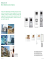
Welcome M
Welcome M
Leading to a flexible and simple world
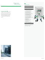
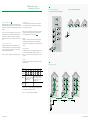
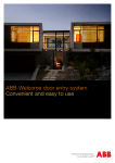
The new door entry system ABB - Welcome M is a new product
range for more flexible application in 2-wire technology.
By the simple 2-wire bus and modular design of outdoor
stations, the installers will have a variety of choices for any kind
of application of single-family house, multi-family buildings and
residential complex, no matter for new buildings or renovation.
Welcome M, it is what you are looking for.
2 | ABB-Welcome M
ABB-Welcome M | 3
Welcome M
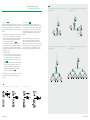
More flexibility and simplicity
Thanks to the modular design and extremely versatile 2-wire bus
system,the new Welcome M range is designed with the concept
of flexibility, simplicity and elegance.Therefore installation and
usage become much easier and more comfortable. With the
wide range of well-designed products, Welcome M meets all
your needs for door entry.
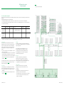
06
10
01
03
05
4 | ABB-Welcome M
07
08
11
09
12
13
02
04
01
02
03
04
05
One-family house
Multi-family house
Apartment building
High rise building
Residential Complex
06
07
08
09
10
11
12
13
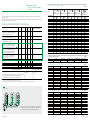
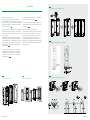
Welcome
Welcome
Welcome
Welcome
Welcome
Welcome
Welcome
Welcome
M
M
M
M
M
M
M
M
video pushbutton outdoor station, white
video pushbutton outdoor station, aluminum
video keypad outdoor station, white
video keypad outdoor station, aluminum
7" video hands-free indoor station, white
4.3" video hands-free indoor station, white
4.3" video handset indoor station, white
audio handset indoor station, 3 buttons , white
ABB-Welcome M | 5
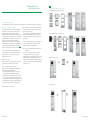
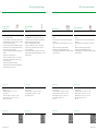
Contents
Terminology
6 | ABB-Welcome M
08
01 Examples for typical ABB-Welcome M system
12
02 Planning ABB-Welcome M system
20
03 Installation
84
04 Commissioning
92
05 Operation
100
06 Overview of product range
102
07 Connection
110
08 Technical assistant tool
124
Legend
126
ABB-Welcome M | 7
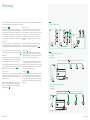
Terminology
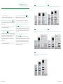
In order to logically and easily understand Welcome M system for installation, terminologies are defined below with illustrations .
It is strongly recommended to read them first before other chapters.
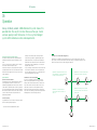
Insulated system Fig.1
The insulated system is a system in which all devices are
managed by one system controller and isolated by a gateway
if get networked. The operation within an insulated system will
work independently and not interrupt other insulated systems.
This is an important concept, both power consumption and
distance calculation are made based on the insulated system.
Common part
The common part is the bus of the networked system —the
insulated system where gate station, gateway(only the part
out of building) and other related system devices are installed.
System C is a typical networked system where the system
controller manages the gate station, guard unit and gateways.
Fig.1
Building part
The building part is the bus of the individual building system
— the insulated system where the outdoor station and indoor
stations and other related system devices are installed.
System A and B are typical building systems where the system
controller manages the outdoor station, gateway, video indoor
distributor, and audio/video indoor stations. Fig.1
Looping connection
Looping connection is a connection layout of devices. With the
looping connection, the same type of devices are connected
one after another. The device can be indoor station, video
distributor or gateway.
System A shows the looping connection of audio indoor
stations in one building, and system C shows the looping
connection of gateway (the ones inside the building) in a
networked system. Fig.1
Fig.1
A,B and C are 3 insulated systems
Branch connection
Branch connection is a connection layout of devices. With
the branch connection, the same type of devices are not
connected with each other like looping connection, sometimes
an additional device, such as a video indoor distributor is
needed. Usually, the branch connection of indoor stations
or gateways is coexisting with looping connection of video
distributor.
System B is a typical branch connection where the indoor
stations are connected by branch and video indoor
distributors are needed with looping connecting. Fig.1
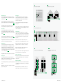
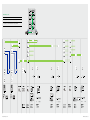
Internal bus Fig.2
The system controller supplies the other bus subscribers
with voltage and controls communication on the 2-wire bus.
Starting from the system controller, the 2-wire bus is divided
into 2 parts — the internal bus and external bus.
Fig.2
Internal bus and external bus in building system
In. — Internal bus
Ex. — External bus
The internal bus is the bus for controlling devices of indoors
or sub insulated system devices. In the building system, it
refers to the bus line from system controller to the last indoor
station. In the networked system, it refers to the bus line from
system controller to the last gateway.
External bus Fig.2
The external bus is the bus for controlling devices of outdoors
of the same insulated system and outdoor related system
devices. In the building trunk system, it refers to the bus line
from system controller to outdoor station. In the networked
system, it refers to the bus line from system controller to the
gate station.
Internal bus and external bus in networked system
In. — Internal bus
Ex. — External bus
Note: Graphic symbols are explained in the legend on page 126
8 | ABB-Welcome M
ABB-Welcome M | 9
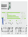
Fig.3
Apartment system for apartments
Apartment system
For multi-insulated systems with multi-system controllers,
when an insulated system is for an apartment, this is called
apartment system. Fig.3
A group of villas/single-families linking into a networked
system can also be taken as one form of apartment system.
Fig.4
The gateway address is set subsequently one upon another
while no addressing is needed at the indoor station.
Floor system
For multi-insulated systems with multi-system controllers,
when an insulated system for a building floor that contains
several apartments ( for example on a floor ) , this is called floor
system. Fig.5
Fig.4
Apartment system for a group of villas
Video system
For insulated system with only one system controller, in
addition to the transmission of the control information, the
audio signal as well as the video signal is transmitted on a
2-wire bus, it is video system.
The right insulated system of Fig.6 (system B) is a typical
video system.
For video systems, at least one video outdoor station should
be present, the indoor station can be purely audio or at least
one video indoor station.
A group of multi-family buildings linking into a networked
system can also be taken as one form of floor system. Fig.6
Outdoor stations
Like one person may have different roles such as father,
employee, etc., the outdoor station can be named differently
when installed in different places. When no specific referring
to certain installing environment, it is called outdoor station
as a general.
The gateway address should be set based on the address of
the first indoor station managed by this gateway.
When the outdoor station is installed in the door of an
apartment or villa, it is called apartment/villa outdoor station.
Building system
For multi-insulated systems with multi-system controllers,
when an insulated system is for one building, this is called
building system. A high-rise building with more than 250
apartments breaking down into several parts and being able
to be called from the same gate station can also be taken as
one form of building system. Fig.7
When the outdoor station is installed in the door for several
apartments on that floor, it is called floor outdoor station.
When the outdoor station is installed in the door for one
building, it is called building outdoor station.
Fig.5
Floor system for apartments in a floor
Fig.6
Floor system for a group of multi-family buildings
When the outdoor station is installed in a general entrance for
the residential complexes, it is called gate station.
Fig.7
Building system for building with more than
63 apartments
The gateway address is set subsequently one upon another.
Audio system
For insulated system with only one system controller, in
addition to the control information(unlock), only audio signal is
transmitted on a 2-wire bus, it is audio system.
The left insulated system of Fig. 6 (system A) is a typical audio
system.
Neither video outdoor station nor video indoor station will be
present in audio systems.
10 | ABB-Welcome M
Parallel outdoor stations
With one system controller, when several outdoor stations are
connected (with different addresses set), it is called parallel
outdoor stations.
Parallel indoor stations
When several indoor stations are set as the same address for
one apartment (expect apartment system), it is called parallel
indoor stations.
While for apartment system, parallel indoor stations use
different addresses, such as the case on page 59 Fig.73.
63 apartments
63 apartments
63 apartments
ABB-Welcome M | 11
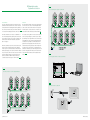
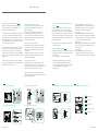
01 Examples for typical
ABB-Welcome M system
Fig.8
Single-family house/villa
» System type: audio/video combined
01
Examples for typical ABB-Welcome M system
Welcome M answers to all your needs in all contexts, no matter
for new construction or renovation of old buildings, no matter
for single-family houses, multi-family houses, high-rise buildings
with more than 250 apartments or residential complex.
Single-family house, audio/video Fig.8
Welcome M system at least consists of a system controller,
outdoor station and indoor station. In Fig. 8 three indoor
stations are installed in one house. When a visitor rings the
bell at the video outdoor station, the call can be answered
at either the 4.3" video hands-free indoor station, the 4.3"
handset video indoor station, or the audio indoor station.
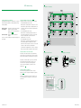
Multi-family building, audio Fig.9
Retrofitting a Welcome M system in a multi-family house with
existing wiring is very easy. Even a plain bell system can be
converted to audio or video system. Depending on the local
circumstances, an installation with recourse to a rising mains,
as shown in Fig.9, is recommended. The wires branch off
on each floor where the existing apartments are located – to
where an audio indoor station with handset is mounted. There
the user can answer incoming calls, open the pedestrian door
and the garage door. Also door bell buttons can be used.
These are connected to the indoor station.
» Wiring: looped from devices to devices
» Devices used
» One video outdoor station, 1-row push button,
article number: M21351P1-A
» One flush mounted box, size 1/2, article number: 41022F
» One mini system controller, article number: M2301
» One 4.3" hands-free video indoor station, white,
article number: M22311-W
» One 4.3" handset video indoor station, white,
article number: M22302-W
» One audio handset indoor station, white,
article number: M22002-W
» One electric door opener (not provided by ABB)
The combined audio/video solution for the one-family houses. The
drawing shows the easy-to-install 2-wire bus. From the door opener
to audio/video outdoor station. And from there to the mini system
controller whose working mode is “one on”. And from there to 4.3"
hands-free indoor station, which loops through to 4.3" handset
indoor station and audio indoor station. No additional distributors are
required.
Fig.9
Multi-family building, audio
» System type: audio
» Wiring: rising mains with branch connections
» Devices used
» One audio outdoor station with the composition of:
one audio module with 1-row push button,
article number:M251022A-.
one cover frame, article number: 51022CF-.
one 4-row push button module, article number:M251021P4
one flush mounted box, size 1/2, article number:41022F
» One mini system controller, article number:M2301
» Ten audio handset indoor station, white,
article number:M22002-W
» One electric door opener(not provided by ABB)
The audio solution for the multi-family houses. The drawing shows
the easy-to-install 2-wire bus from the electrical door opener to
outdoor audio station, from there to the system controller and from
there to the audio indoor station with handset. No additional
distributors are required. In case of future renovation into video
system, then a video distributor is needed for every 4 indoor
stations.
12 | ABB-Welcome M
ABB-WelcomeMM| 13
| 13
ABB-Welcome
01 Examples for typical
ABB-Welcome M system
Fig.10
High-rise building, audio/video
» System type: audio/video combined
» Wiring: branch line by distributor connection
High-rise building, audio/video Fig.10
The setup of a video system or a combined audio/video
system can include an existing rising mains. To correctly
distribute the video image of the outdoor station inside the
house, video distributors are installed in each branch box.
Once one system controller can not cover all the power
consumption of the devices, additional power supply in the
bus should be added by the combination of gateway and
system controller.
Group of villas, audio/video Fig.11
For a group of villas/single-family houses, a gate station can
be equipped as the main entrance. The gateway installed in
each villa/single-family ensures the independent operation of
each villa/single-family and links the whole group as a
networked system.
» Devices used
» One keypad outdoor station,
article number: M21351K-./M21352K-.
» One flush mounted box, size 1/4, article number: 41024F
» Three system controller, article number: M2300
» Two gateway, article number: M2302
» Twenty five video indoor distributor, article number: M2304
» Fifty audio handset indoor station. white,
article number:M22002-W
» Fifty video 4.3’’ hands-free indoor station. white,
article number:M22311-W
» One electric door opener(not provided by ABB)
The audio/video combined solution for high-rise buildings. The
drawing shows the easy-to-install 2-wire bus from the electrical door
opener to outdoor audio station, from there to the system controller
and from there to the audio indoor station with handset. An
additional system controller and a gateway works as auxiliary power
supply are needed to support the bus line for power consumption.
Fig.11
Group of villas, audio/video
» System type: audio/video combined
» Wiring: branch line by distributor connection
» Devices used
» One video outdoor station(16 pushbuttons)
with the composition of:
one camera module, article number: M251021C
one audio module, article number: M251021A-.
one cover frame, article number: 51024CF-.
two pcs of 4-row pushbutton module,
article number: M251021P4
one flush mounted box, size 1/4, article number: 41024F
» One system controller, article number: M2300
» Four video indoor distributor, article number: M2304
» Sixteen sets of villa kit, article number: M20001/ M20321
» Sixteen of gateway, article number: M2302
» One electric door opener (not provided by ABB)
The solution for a group of villas/single-family houses networked
together. The drawing shows the easy-toinstall 2-wire bus from
the electrical door opener to gate station, from there to the system
controller from there to the video indoor distributor, and from there to
villa system and to video hands-free indoor station. Each villa system
should add a gateway to be insulated from the networked bus.
14 | ABB-Welcome M
ABB-Welcome M | 15
01 Examples for typical
ABB-Welcome M system
Fig.12
High-rise building with floor entrance, video
» System type: audio/video combined
» Wiring: branch line by distributor connection
High-rise building with floor entrance, video Fig.12
For a high-rise building, on which floor, a pushbutton outdoor
station is present as the second entrance to reach the
apartment door. The gateway installed on each floor ensures
their independent operation within the building.
Resident complexes, audio/video Fig.13
For residential complexes that may include villa/single-family
houses, multi-family houses and high-rise buildings, usually
common gate station(s) are present with guard unit(s). The
gateway installed in each villa/single-family/high-rise building
ensures their independent operation within the building and
links the whole group as a networked system.
» Devices used
» One keypad outdoor station,
article number: M21351K-./M21352K-.
» One flush mounted box, size 1/4, article number: 41024F
» Five video outdoor stations, each with the composition of:
one came modules, article number: M251021C
one audio modules, article number: M251023A-.
one cover frame, article number: 51022CF-.
one flush mounted box article number: 41022F
» One system controller, article number: M2300
» Five mini system controller, article number: M2301
» Five gateway, article number: M2302
» Five video indoor distributor, article number: M2304
» Fifteen 4.3 video hands-free indoor station, white,
article number: M22311-W
» Six electric door opener(not provided by ABB)
The solution for high rise buildings when a second entrance on each
floor is needed. The drawing shows the easy-to-install 2-wire bus
from the electrical door opener to outdoor station, from there to the
system controller, from there to floor gateway, and from there to floor
system and to video hands-free indoor station. Each floor system
should add a gateway to be insulated from the networked bus.
Fig.13
Residential complexes, audio/video
» System type: audio/video combined
» Wiring: branch line by distributor connection
» Devices used
» One keypad outdoor station,
article number: M21351K-./M213512K-.
» One flush mounted box, size 1/4, article number: 41024F
» Two video outdoor station, each with the composition of:
one camera module, article number: M251021C
one audio module, article number: M251023A-.
one cover frame, article number: 51022CF-.
one flush mounted box, article number: 41022F
» Two audio outdoor station, each with the composition of:
one audio module with 1-row pushbutton,
article number:M251022A-.
one 4-row pushbutton module, article number:M251021P4
one cover frame, article number: 51022CF-.
one flush mounted box, size 1/2, article number:41022F
» Five mini system controller, article number: M2301
» One video indoor distributor, article number: M2304
» Four gateway, article number: M2302
» Eight 4.3” hands-free video indoor station, white
article number: M22311-W
» Twenty audio handset indoor station. white
article number: M22002-W
» Five electric door opener (not provided by ABB)
The solution for residential complex. The drawing shows the easy-toinstall 2-wire bus from the electrical door opener to gate station, from
there to the system controller, from there to video distributor, and
from there to each insulated building system and to audio handset
indoor station. Each building system should add a gateway to be
insulated from the networked bus.
16 | ABB-Welcome M
ABB-Welcome M | 17
01 Examples for typical
ABB-Welcome M system
Fig.14
Commercial objects, video/audio
» System type: audio/video combined
» Wiring: looped from devices to devices
Commercial objects, audio/video Fig.14
For buildings with several entrances (doctor's office, law firm,
small workshops, etc.), these can be individually equipped
with outdoor stations. A combination of audio outdoor stations
and video outdoor stations is possible. For this application a
video outdoor distributor as MDRC unit must be used. The
door, from which the bell is rung, is opened by the indoor
station called.
» Devices used
» Two video outdoor station, each with the composition of:
one camera module, article number: M251021C
one audio module, article number: M251023A-.
one cover frame, article number: 51022CF-.
one flush mounted box, article number: 41022F
» Two audio outdoor station, each with the composition of:
one audio module article number: M251023A-.
one cover frame, article number: 51021CF-.
Two flush mounted box, article number: 41021F
» One system controller, article number: M2300
» Three video outdoor distributor, article number: 83325/2-500
» One audio handset indoor station. White,
article number: M22002-W
» One video hands-free indoor station. White,
article number: M22311-W
» One video handset indoor station. White,
article number: M22301-W
» Four electric door opener(not provided by ABB)
The solution for commercial object with more than 2 entrances. The
drawing shows the easy-to-install 2-wire bus connect indoor stations
and multi outdoor stations. The outdoor distributor is needed to
connect the multi outdoor stations together.
18 | ABB-Welcome M
ABB-Welcome M | 19
02 Planning the system
02
Planning ABB-Welcome M system
Either by providing an all-round and easy-to-understand table to
grasp all the possibilities of the combination of outdoor station,
indoor station and system device, or by supplying a few simple
rules for flexible topology and power consumption and distance
calculation to meet the project requirement, this makes even
complex projects easy to manage and easy to implement at a
later stage.
The ABB-Welcome M door communication can be used purely
as a 2-wire bus system in new buildings and for modernizing
existing systems. In most cases, the existing lines can be
used. The universally used 2-wire bus technology allows a bell
system to be upgraded to a video system with outdoor
camera.
Welcome M system can be set up with one system controller
or with multi-system controllers. For both types, every system
controller makes an insulated system.
This chapter includes below sections to make the planning job
easier
2.1 Capacity of Welcome M system
2.2 Selection of the outdoor station
2.3 Selection of the indoor station
2.4 Selection of the system devices
2.5 System topology
2.6 Power consumer calculation and distance calculation to
an insulated system
2.7 Easy reference for the modular outdoor station solution
For each insulated system, it can be purely an audio
system. In the building part, visitors and residents use it to
communicate between audio outdoor station and audio indoor
station. In the common part, if a guard unit is present, the
visitor and guard can communicate with each other.
The insulated system can also be a video system.
This makes the camera image of the video outdoor station
visible at the video indoor stations in the building part, or
image of video gate station visible at the guard units in the
common part.
20 | ABB-Welcome M
ABB-Welcome M | 21
02 Planning the system
System capacity
Fig.15
Capacity of Welcome M system
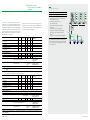
2.1 Capacity of Welcome M system
The system capacity is determined by the valid address number of the devices. Two kinds of addressing are used in Welcome
M system:
Independent addressing and combined addressing.
» For independent addressing, the devices' addresses are independent in the common part and in the building part.
» For combined addressing, the total address number of the devices in every building and the devices in common part-should
be less than a certain value.
Total address:
Outdoor station
Indoor station
Gateway
Guard unit
Switch actuator
-
250
60 - building gateway mode
9
-
-
199
99 - apartment/Floor gateway mode
(independent
addressing)
Total address:
9
-
-
(combined
addressing)
* Total address of independent addressing =Common part or every individual building part, two parts are independent
Total address of combine addressing =Common part + every individual building part , two parts are combined
Outdoor station
The outdoor station of Welcome M system includes the
building outdoor station ,villa outdoor station, gate station,
and second confirmed outdoor station. The total address
number of outdoor stations is 9 for all kinds of entry level.
The following are some examples of the address of door
stations:
» In one video system with only one building/villa, 9 outdoor
stations can be installed.
» In a networked system, 4 gate stations in the common part,
and each building has 4 building outdoor stations and one
second confirme doutdoor station in each of the apartment,
total 9(4+4+1) outdoor stations can be installed for the
apartment. Fig.15(B4)
Or 5 building outdoor stations for one villa and 4 gate stations
in the common part, total 9 (5+4) outdoor stations can be
installed for the apartment. Fig.15(B54)
Indoor station
In a single building or in the building part of a networked
system, the total address number of indoor stations is 250.
» In one audio/video system for one building of up to 250
apartments.
» In one networked system, with each building of up to 250
apartments Fig.15(B1)
22 | ABB-Welcome M
Gateway
The address of gateway is using independent addressing.
The total address of gateway varies when it is set as different
modes for application.
The total address number of gateway when it is set
as apartment gateway or floor gateway is 99. While
the available number of address of gateway when set
as building gateway is 60. Please refer to page 41-45
for gateway setting for application.
Guard unit
The address of guard unit is using independent
addressing. Total up to 9 guard units is allowed in a
video system of one building or in the building part of
networked system. And in one networked system, total up
to 9 guard units is allowed in the common part.
Switch actuator
The address of switch actuator is using combined
addressing. Total up to 199 switch actuators can be
connected.
For example:
» In a system with one building of 199 apartments, each
apartment can install one switch actuator.
» In a networked system, 4 switch actuators can be installed
in the common part, and 195 switch actuators can be
installed in every building.
ABB-Welcome M | 23
02 Planning the system
Outdoor station selection
Fig.16
Composition of an pushbutton outdoor station
Audio pushbutton outdoor station composition
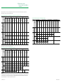
2.2 Selection of the outdoor station
Welcome M provides a wide range of outdoor stations with pushbutton by the combination of the modules, covers and boxes.
Composition of pushbutton outdoor station
For pushbutton outdoor stations, it multiples the application
by setting as one column or double column for the same
pushbutton module. The setting is made by the audio
modules. We call the different pushbutton status "single row"
or "double row". 3-row pushbutton and 4-row pushbutton are
optional for application. For pushbutton outdoor stations, to
compose an outdoor station, audio module (with no
pushbutton, with 1-row pushbutton or 2-row pushbutton),
pushbutton module (3-row pushbutton or 4-row pushbutton),
cover frame and flush mounted boxes are compulsory. If
surface mounting is required, a rain hood is needed. Fig.16
There is a quick composition table for pushbutton outdoor
station on page 26-27. Please follow the guide below and
refer to the table to choose the articles for the desired
pushbutton outdoor station.
Step 1: Audio or video?
Please refer to page 26 for audio pushbutton outdoor station
and page 27 for video pushbutton outdoor station.
Please decide whether single row or double row pushbutton
is needed, then please turn to the button ranges to quickly
locate the possible composition.
» In case the light and call guard functions are required for
the outdoor station, then the total buttons should be the
combination of the apartment no. and button number for
extra functions.
Video pushbutton outdoor station composition
» In case it is not sure whether single or double pushbuttons
for one row is optimal, it is also possible to turn to the
pushbutton range to see all the possibilities.
Step 4: Choose the right composition by balancing the cost
and esthetics
» There may be more than one possibility of compositing
outdoor station in certain cases by choosing 3-row
pushbutton module or 4-row pushbutton module, choosing
a nameplate module or not and setting as single row or
double row for the same pushbutton module. It is advised to
consider the cost and esthetics together when making the
composition decision.
Nameplate module use case
Step 2: 3-row pushbutton or 4-row pushbutton?
Please refer to the 3-row pushbutton or 4-row pushbutton
table for different pushbuttonapplication.
» It is technically possible but esthetically, inconsistent for
combining audio module with pushbutton and 3-row
pushbutton module. For better appearance as an outdoor
station, the composition of pushbuttons follows the rule that
every pushbutton should have the same height. Thus if 3-row
pushbutton module is used, audio module with pushbutton
and 4-row pushbutton module are not recommended.
Step 3: How many calls are needed?
24 | ABB-Welcome M
Rainhood use case
ABB-Welcome M | 25
02 Planning the system
Outdoor station selection
Audio outdoor station
Video outdoor station
3-row pushbutton
3-row pushbutton
Article No.
Button Range
Single
Row*
Double
Row*
Pushbutton Module
&
Nameplate Module
Audio Module
M251021A-.
M251022A-.
x1
M251023A-.
x1
Single
Double
Single
Double
M251021P3
51021DN
Article No.
Button Range Camera
Module
Cover Frame & Flush Mounted Box
51021CF-. + 51022CF-. + 51023CF-. + 51024CF-. + 51028CF-. + 51025CF-. + 51026CF-. + 51029CF-. + 51024CF-. + 41024F
41021F
41022F
41023F
41024F
41028F
41025F
41026F
41029F
+ 51021J
Single Double M251021C
Row* Row*
x1
Single
Audio Module
M251021A-.
x1
Double
1-2
1-4
1
1-2
2
1-4
3-5
5 - 10
3
5-6
4
7-8
5
9 - 10
x1
6-8
11 - 16
6
11 - 12
7
13 - 14
8
15 - 16
x2
9 - 11
17 - 22
9
17 - 18
10
19 - 20
11
21 - 22
x3
12 - 14
23 - 28
12
23 - 24
13
25 - 26
14
27 - 28
x4
15 - 17
29 - 34
15
29 - 30
16
31 - 32
17
33 - 34
x5
18 - 20
35 - 40
18
35 - 36
19
37 - 38
20
39 - 40
x6
21 - 23
41 - 46
21
41 - 42
22
43 - 44
23
45 - 46
x7
24 - 26
47 - 52
24
47 - 48
25
49 - 50
26
51 - 52
x8
27 - 29
53 - 58
27
53 - 54
28
55 - 56
29
57 - 58
x9
30 - 32
59 - 64
30
59 - 60
31
61 - 62
32
63 - 64
x10
33 - 35
65 - 70
33
65 - 66
34
67 - 68
35
69 - 70
x11
x1
x1
x1
Pushbutton Module
&
Nameplate Module
M251022A-.
x1
M251023A-.
x1
Single
Double
Single
Double
M251021P3
51021DN
Cover Frame & Flush Mounted Box
51022CF-. + 51023CF-. + 51024CF-. + 51028CF-. + 51025CF-. + 51026CF-. + 51029CF-. + 51024CF-. + 41024F
41022F
41023F
41024F
41028F
41025F
41026F
41029F
+ 51021J
x1
Single
Double
1-2
1-4
1
1-2
2
1-4
3-5
5 - 10
3
5-6
4
7-8
5
9 - 10
x1
6-8
11 - 16
6
11 - 12
7
13 - 14
8
15 - 16
x2
9 - 11
17 - 22
9
17 - 18
10
19 - 20
11
21 - 22
x3
12 - 14
23 - 28
12
23 - 24
13
25 - 26
14
27 - 28
x4
15 - 17
29 - 34
15
29 - 30
16
31 - 32
17
33 - 34
x5
18 - 20
35 - 40
18
35 - 36
19
37 - 38
20
39 - 40
x6
21 - 23
41 - 46
21
41 - 42
22
43 - 44
23
45 - 46
x7
24 - 26
47 - 52
24
47 - 48
25
49 - 50
26
51 - 52
x8
27 - 29
53 - 58
27
53 - 54
28
55 - 56
29
57 - 58
x9
30 - 32
59 - 64
30
59 - 60
31
61 - 62
32
63 - 64
x10
x1
x1
x1
51022RH
51021RH
51022RH
51023RH
51024RH
51028RH
51025RH
51026RH
51029RH
51023RH
51024RH
51028RH
51025RH
51026RH
51029RH
51027RH
51027RH
* Optional to install rain hood
* Optional to install rain hood
4-row pushbutton
4-row pushbutton
Article No.
Button Range
Single
Row*
Double
Row*
Pushbutton Module
&
Nameplate Module
Audio Module
M251021A-.
M251022A-.
x1
M251023A-.
x1
Single
Double
Single
Double
M251021P3
51021DN
51021CF-. + 51022CF-. + 51023CF-. + 51024CF-. + 51028CF-. + 51025CF-. + 51026CF-. + 51029CF-. + 51024CF-. + 41024F
41021F
41022F
41023F
41024F
41028F
41025F
41026F
41029F
+ 51021J
Single Double M251021C
Row* Row*
x1
Single
1-2
1-4
1
1-2
2
1-4
7 - 12
4
7-8
5
9 - 10
6
11 - 12
x1
8 - 10
15 - 20
8
15 - 16
9
17 - 18
10
19 - 20
x2
12 - 14
23 - 28
12
23 - 24
13
25 - 26
14
27 - 28
x3
16 - 18
31 - 36
16
31 - 32
17
33 - 34
18
35 - 36
x4
20 - 22
39 - 44
20
39 - 40
21
41 - 42
22
43 - 44
x5
24 - 26
47 - 52
24
47 - 48
25
49 - 50
26
51 - 52
x6
28 - 30
55 - 60
28
55 - 56
29
57 - 58
30
59 - 60
x7
32 - 34
63 - 68
32
63 - 64
33
65 - 66
34
67 - 68
x8
36 - 38
71 - 76
36
71 - 72
37
73 - 74
38
75 - 76
x9
40 - 47
79 - 84
40
79 - 80
41
81 - 82
42
83 - 84
x10
44 - 46
87 - 92
44
87 - 88
45
89 - 90
46
91 - 92
x11
x1
x1
x1
51021RH
* Optional to install rain hood
51022RH
51023RH
51024RH
51028RH
51025RH
51026RH
51029RH
Pushbutton Module
&
Nameplate Module
Audio Module
M251021A-.
x1
Double
4-6
26 | ABB-Welcome M
Article No.
Button Range Camera
Module
Cover Frame & Flush Mounted Box
M251022A-.
x1
M251023A-.
x1
Single
Double
Single
Double
M251021P3
51021DN
Cover Frame & Flush Mounted Box
51022CF-. + 51023CF-. + 51024CF-. + 51028CF-. + 51025CF-. + 51026CF-. + 51029CF-. + 51024CF-. + 41024F
41022F
41023F
41024F
41028F
41025F
41026F
41029F
+ 51021J
x1
Single
Double
1-2
1-4
1
1-2
2
1-4
4-6
7 - 12
4
7-8
5
9 - 10
6
11 - 12
x1
8 - 10
15 - 20
8
15 - 16
9
17 - 18
10
19 - 20
x2
12 - 14
23 - 28
12
23 - 24
13
25 - 26
14
27 - 28
x3
16 - 18
31 - 36
16
31 - 32
17
33 - 34
18
35 - 36
x4
20 - 22
39 - 44
20
39 - 40
21
41 - 42
22
43 - 44
x5
24 - 26
47 - 52
24
47 - 48
25
49 - 50
26
51 - 52
x6
28 - 30
55 - 60
28
55 - 56
29
57 - 58
30
59 - 60
x7
32 - 34
63 - 68
32
63 - 64
33
65 - 66
34
67 - 68
x8
36 - 38
71 - 76
36
71 - 72
37
73 - 74
38
75 - 76
x9
40 - 42
79 - 84
40
79 - 80
41
81 - 82
42
83 - 84
x10
x1
x1
x1
51022RH
51027RH
51023RH
51024RH
51028RH
51025RH
51026RH
51029RH
51027RH
* Optional to install rain hood
ABB-Welcome M | 27
02 Planning the system
Outdoor station selection
Options of keypad outdoor station
For condominium buildings and residential complexes, it is
recommended to choose keypad outdoor station.
Keypad with the pushbutton outdoor station Fig.19
Keypad provides the keyless access for the residents of the
building by inputting the correct password.
Keypad with pure audio module outdoor station Fig.17
Besides the keyless access by inputting the correct password,
it can also be used for inputting the correct call code to call
the indoor stations.
It is a good solution especially for the villa/singlefamily
house solution. Then the pushbutton is largely for visitors only.
The call code is default starting from 1, which will call the
indoor station with the address of 1.
Keypad and display (in-built RFID reader) with pure audio
module outdoor station Fig.18
The display with in-built ID/IC reader can be used for multiple
uses: keyless access by reading the registered proximity card,
displaying some welcome messages, showing the status of
calling progress, or processing the programming.
Upon programming, the name or call code can also be
displayed on the screen and scrolled up and down on the
keypad module.
The call code is default starting from 1, which will call the
indoor station with the address of 1.
Display(in-built RF reader) with the pushbutton outdoor
station Fig.20
ID/IC proximity reader can be useful also for residents' keyless
access by reading the registered proximity card. In case lost,
it can also be easily wiped out in the system and a new card
can be efficiently registered. Then the push button is largely
for visitors only.
Fig.17
Keypad with pure audio module outdoor station
Fig.19
Keypad with pushbutton outdoor station
Fig.18
Keypad and display (in-built RFID reader )with pure audio
module outdoor station
Fig.20
Display (in-built RFID reader) with pushbutton outdoor station
Keypad and display(in-built RF reader) with pushbutton
outdoor station Fig.21
It is the combination of keypad outdoor station and push
button outdoor station. It provides the most convenient calling
experience for the residents and the visitors. For the residents,
he can input the correct password or swipe the registered
proximity card. He can also press the push button or scroll
up and down the screen and press call button in case the
resident's name is stored there.
Fig.21
Keypad and display (in-built RFID reader) with pushbutton
outdoor station
28 | ABB-Welcome M
ABB-Welcome M | 29
02 Planning the system
Indoor station selection
2.3 Selection of the indoor station
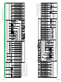
In addition to the appearance, to select the indoor station for application needs to consider the functions needed for the
project. The table below gives a general function list for the indoor station for application.
Functions
7" all touch video handsfree
4.3" video hands-free
** 4.3" video handset
Audio handset
indoor station
indoor station
indoor station
indoor station
* Secret conversation
x
x
x
x
* Cyclical surveillance
x
x
x
x
* Manual call
x
x
x
x
* Door bell call
x
x
x
x
* Remote unlock
x
x
x
x
* Control two locks
x
x
x
x
* Room to room call
x
x
x
x
* Home to home call
x
x
x
x
* Paging/Broadcast
-
x
x B/W(-)
-
* Black list
x
x
x B/W(-)
-
* Call guard unit
x
x
x
x
* SOS
x
x
x
x
* Image saving
x
x
x B/W(-)
-
* Customized audio message
x
-
-
-
* Call forward
x
x
x B/W(-)
-
* Door status check
x
x
x
x
Variable ringtone
x
x
x
x
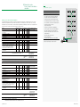
Secret conversation Fig.22
During the conversation between the outdoor station and the
indoor station, all outdoor stations and indoors that are not
involved in the conversation are temporarily excluded in order
to guarantee the privacy of video door entry conversations.
When calling from an outdoor station that is temporarily
excluded, a time-out will indicate that the extension line is
momentarily busy.
Cyclical surveillance
Fig.23
All indoor stations are equipped with a surveillance button
which can be used to connect the outdoor stations at any
time. The user sees the images from the default outdoor
station; press repeatedly the button to display images from
the additional camera (if present) connected to the default
outdoor station, and then from other outdoor stations.
Fig.22
Secret conversation
Manual call Fig.24
During surveillance, by picking the handset up or activating
audio in case of hands-free stations, the user starts a
conversation with the selected call station.
Door bell call Fig.25
Indoor stations are provided with two terminal pins used
to connect the door bell button. If the button is pressed,
the indoor station emits an about 3s ring, according to the
selected call ring tone (different from those of the other calls).
If the user has several indoor stations in parallel, and
connect this button only to one indoor station, all indoor
stations will ring together.
Fig.24
Manual call
leaving
x
x
x
-
* Picture frame and screen saver
Customized password for keypad
x
-
-
-
* Automatic unlock
x
x
x
x
* QR code for user manual reach
x
x
x
-
* Mute one or mute all
x
x
x
- only mute itself
* Induction loop
-
x
x B/W(-)
x
Local power supply
-
x
x
-
Surface mounted installation
x
x
x
x
Desktop installation
x
x
x
-
Flush-mounted installation
-
x
-
-
Fig.23
Cyclical surveillance
Fig.25
Door bell call
Notes:
* For the function description, please find the explanation in the following pages.
** There are two versions of 4.3” video handset indoor station – color version and the B/W, differ from the color or B/W TFT screen. For B/W
version there are some limited functions compared to color version.
30 | ABB-Welcome M
ABB-Welcome M | 31
02 Planning the system
Indoor station selection
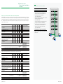
Remote unlock Fig.26
With the system at reset, the user can open the lock of the
default outdoor station at any time. If during conversation,
the user can release the door lock associated to the outdoor
station making the call .
Control two locks Fig.27
Two locks can be connected with outdoor station, one is for
pedestrian gate and the other is for driveway gate. User can
press "unlock" button and programmable button (e.g. button 1,
release 2ndlock function is programmed first) to control the
two doors respectively.
Room to room call&Home to home call Fig.28
If there are several indoor stations in parallel, after
programming an indoor station for internal intercom function,
user can activate the intercom call at this indoor station, all
other indoor stations will ring together.
For several different apartments, after programming an indoor
station for external intercom function, user can activate the
intercom call at this indoor station, the called indoor station
will ring.
Paging/Broadcast Fig.29
User can activate the broadcast function by entering
broadcast menu, a message can be forwarded through all IS
in the same apartment.
Fig.26
Remote control
Remote unlock at any time for default outdoor station
Fig.28
Room to room call
Home to home call
Blacklist Fig.30
To be safe, for home to home call the unwanted caller can be
set in blacklist.
Call guard unit Fig.31
This function allows establishing a communication with the
guard unit. Enter communication menu to send the call to the
guard unit or press a programmable button (call guard unit
function is programmed first ) to activate the call.
Fig.29
Fig.30
Blacklist
Paging/Broadcast
……
Send SOS Fig.32
If there is emergency, user can send an SOS message to
guard unit by pressing programmable button 1 for 3s. Guard
unit will receive the SOS message and indicates which
apartment is sending SOS.
Image saving Fig.33
Users can find who has recently been at the door and what
happened to him by history menu. Either manual snapshots
during conversation or automatic snapshots after bell ringing
in your absence will be saved in history.
BLACKLIST
BLACKLIST 1
(001)
Add New
Fig.31
Fig.32
Call guard unit
Send SOS
Customized audio message leaving Fig.34
Before going out you can record an audio message for a
family member or visitors who ring the bell.
SOS
>3s
Fig.27
Control 1st and 2nd locks
Fig.33
Fig.34
Image saving
Customized audio message leaving
HIS
TORY
Date Time
-
32 | ABB-Welcome M
Di
rection
2013-03-22
01:05
Indoor-001
2013-03-22
01:12
Out doo
r-1
2013-03-22
01:15
Out doo
r-1
ABB-Welcome M | 33
02 Planning the system
Indoor station selection
Fig.35
Fig.36
Call forward
Door status check
≥120s
5s
Call forward Fig.35
It is possible to forward the income calling when absent from
home. Through the setting at indoor station before leaving
home, the incoming call can be forwarded from home to the
selected neighbor or the guard unit.
Fig.36
Door status check
A sensor is connected with outdoor station, if this door is
open for over 120s, LED of unlock button of indoor stations
and guard units will flash. When the door is closed, the LED
will be off. If 2 or more outdoor stations are associated, the
LED will be off when all outdoor stations are closed and will
flash when at least one outdoor station is open.
Variable ringtone
Users can select the ring tone for default outdoor station or
other outdoor stations or the door bell ring tone among the 5
available ones.
Customized password for keypad
Users can set a private password (6-8 digits) at indoor station
just at home, which is easy to remember.
Picture frame and screen saver Fig.37
When the indoor station is at standby, its appearance will
add the decor of the room. With a SD card the indoor station
can display high-resolution files from the computer or camera
directly on the touch display. The display time can be adjusted
optionally.
>5s
Automatic unlock Fig.38
This function is used mainly in the service sector (offices,
doctors, professional). This feature can be activated or
deactivated at the indoor station. With the function activated,
LED unlock will light, and after receiving a call, unlock
command will be sent automatically.
QR code for user manual reach Fig.39
Users can scan QR-Code contained in the menu of video
indoor stations directly to get the detailed manual. While for
audio indoor station, QR-Code is contained in the quick guide.
Fig.37
Picture frame and screen saver
Fig.38
Automatic unlock
8:00 -12:00
Mute one / mute all indoor station Fig.40
User can mute the ringtone when there's an incoming call.
Press the mute button to mute the indoor station. If the user
has several indoor stations in parallel, long-press the mute
button for about 3s at one indoor station, and all indoor
stations will mute together when there's an incoming call.
When the function is activated, the LED MUTE turns on.
Induction loop Fig.41
Indoor station with an induction loop allows hearing-impaired
persons to wear a hearing aid (working in "T" mode) to hear
the ringtone and the voice of visitors.
AUTO UNLOCK
Auto Unlock
A
Time 1T
08
I
-
ime 2
:
12
00
:
00
:
00
00
Disable call
forward.
Fig.39
QR code for user manual reach
Fig.40
Mute one and mute all
Local power supply
Indoor station can be powered by an additional power supply
when a parallel indoor station needs to be installed without
impact on the whole system.
Fig.41
Induction loop for hearing aid
34 | ABB-Welcome M
ABB-Welcome M | 35
02 Planning the system
System device selection
Fig.42
Application of system controller, local power supply and auxiliary power supply
2.4 Selection of system devices
It’s important to select the appropriate system devices to set up a Welcome M system. It needs to consider both the function
of the devices and topology for application. System controller is a must for any insulated system, other system devices can be
selected to meet the specific project requirement.
System controller, local power supply and auxiliary power
supply
System controller provides both power and communication
command for a Welcome M system. As the extension of
system controller, auxiliary power supply and local power
supply serve as the supplement to provide a flexible power
solution to meet the requirement of all kinds of Welcome M
system. The given illustration is a project case using three
power sources. Fig.42
System controller
Working as the "brain“ of all devices, a system controller is
compulsory and exclusive in any insulated system . It not only
provides power, but also manages all the communication and
control between outdoor stations and indoor stations in the
building part ,and between gate stations and the gateway in
the common part.
For those systems with multi-system controllers , it will
be broken down into several insulated systems and every
insulated system needs separate power consumption and
distance limit calculation. (See page 60-63)
Both standard system controller and mini system controller
are provided to meet different project needs.
The system controller has two working modes: “all on” and
“one on”, "all on" and "one on" are system behavior for
screen switching on for the indoor stations with the same
address(parallel indoor stations) in case of being called. Under
"all on", the master video indoor station and other slave
video indoor station(s) will all switch on the screens and ring
at the same time upon being called from the outdoor stations
or gate stations. Under "one on", only the "master" video
indoor station will switch on the screen and ring, the other
"slave" video indoor station(s) will ring but will not switch on
the screen. Fig.43
Power units of system controller
As system controller will provide the power for the system, it
is important to calculate the available power unit of standard
system controller or mini system controller for the system
before application.
For a 2-wire system, the available power unit of a system
controller needs to take the situation of 1 or ≥ 2 apartments
into consideration firstly.
Auxiliary power supply
To achieve a comfortable door communication experience in
applications, different value of working power will always be
reserved first to handle the simultaneous working of different
devices(door call, setting, door bell) before allocated to the
standby devices.
Since the power calculation is based on the remaining standby
current after subtracting the varied reserved working current
in 1 or ≥ 2 apartments, thus, the power units of system
controller varies when the system contains 1 or ≥ 2
apartments, which has been revealed in Table 1 (page 61 ).
Auxiliary power supply
System controller
Moreover, the "all on" and "one on" mode setting will impact
the power consumer calculation when one apartment contains
more than one video indoor station(parallel indoor stations).
As we can see from the power and distance table in Table
1 on page61, for one additional video 4.3" indoor station
when the system controller is under "all on" mode, 23 more
consumer units should be counted, while only 11 consumer
units are counted when system controller is under "one on"
mode. In the real project, the balance can be made between
cost and comfort.
Local power supply
Fig.43
“All on” and “One on” setting of system controller
Master
Slave
Slave
Master
Slave
Slave
All on
One on
36 | ABB-Welcome M
ABB-Welcome M | 37
02 Planning the system
System device selection
Local power supply
Local power supply and system controller are exactly the
same devices, but they are named differently because of the
different functions they serve.
» Local power supply only provides the pure power source
without giving communication command like system
controller.
» Unlike the system controller or auxiliary power supply that
provides the power for all the devices in the external and
internal bus line through the 2-wire bus terminal, local
power supply provides the pure power to individual device
directly by connecting the local power supply terminals.
» Devices below contain local power supply terminals, and
can be powered by local power supply:
» Audio module of outdoor station
» 4.3” video handset/hands-free indoor station
» Guard unit
Despite the physical product is like system controller, the
working mode setting of local power supply is useless .
Power units of local power supply
One mini local power supply can feed :
» Up to 4 pcs of parallel 4.3" video hands-free indoor station
» Up to 4 pcs of parallel 4.3" video handset indoor station
» Up to 4 pcs of parallel guard units
» 1 pc of any kind of pushbutton outdoor station
» 1 pc of any kind of keypad outdoor station
Despite one standard local power supply doubles the capacity
compared to one mini local power supply, the real user cases
will not need it due to the letter already can fulfill the needs.
For parallel 4.3” video indoor stations in one apartment, the
screen of any one fed by local power supply will always be on
for incoming call even in “one on” setting in system controller.
Fig.44
Local power supply for parallel indoor stations
The increased number of devices can be the increased
quantities of apartments in one building or the increased
quantities of apparel indoor stations within one apartment.
Based on the calculation rule in Table 1 (page 61), specifically,
for scenarios below when the power units of one system
controller is smaller than required consumer units of devices,
local power supply is highly recommended. This is due to the
fact that compared to auxiliary power supply, local power
supply solution will be less cost and easier wiring:
» When the total consumer units of external and internal
bus > power unit of system controller, while the total
consumer units of the devices on internal bus ≤ power unit
of system controller, one or all outdoor stations should
be powered by local power supply. See the application on
page 68(example 3)
» When feeding the local power supply to parallel slave 4.3"
video hands-free or 4.3" video handset indoor station(s),
the total power consumer units will become ≤ power units
of system controller. Fig.45
» When feeding the local power supply to guard unit, the
total power consumer units will become ≤ power units of
system controller.
» When adding the parallel 4.3" video hands-free or 4.3"
video handset indoor station to an apartment after the door
communication system installation had been finished in the
past. Since the additional device might cause the system
controller inadequate to cover the increased consumer
units, it is safe to put local power supply to additional 4.3"
indoor station to that certain apartment without affecting
the existing power solution. Fig.46
Fig.45
Feed parallel 4.3” video indoor stations by mini local power supply
Note:
1. Standard system controller “all on” mode, supports 1 outdoor
station + 5 parallel 4.3” video hands-free indoor stations
2. Mini local power supply, feeds 4pcs 4.3 video hands-free indoor
stations
Note:
1. Standard system controller “all on” mode, supports 1 outdoor
station + 3 parallel 7” video hands-free indoor stations
2. Mini local power supply, feeds 4pcs 4.3 video hands-free indoor
stations
Fig.46
Add parallel 4.3” video indoor stations to apartments after installation
Fig.44
When the device is fed by local power supply, it requires rather
small power consumer unit from the system controller. For
easy calculation, it is taken as "0" power unit during the power
consumer calculation, which is shown in Table 1 on page 61.
The saved power of system controller can be used to increase
the number of devices under this system controller.
Note:
In 2013, the door entry system for this building had been installed.
Later on, Apartment A, B and/or C can also equire to add one more
video indoor station with local power supply without affecting other
users.
38 | ABB-Welcome M
ABB-Welcome M | 39
02 Planning the system
System device selection
Auxiliary power supply
For one insulated system, when adding the local power
supply to the devices in external bus or internal bus, or both
ways still can not cover the required consumption units of the
devices, auxiliary power supply is suggested. The combination
of gateway(under auxiliary power supply mode) and system
controller will make an auxiliary, which can be used to split the
system into two insulated systems. Fig.47
Like system controller, the "all on" and "one on" mode setting
will impact the power consumption calculation when of parallel
indoor stations.
Power units of auxiliary power supply
The Table 1-2 on page 62 can be used to count devices
powered by auxiliary power supply. To have an easy reference
please check Table 3-2, Table 3-3 and Table 3-4 on page
76-77, the capacity of both mini auxiliary power supply and
standard auxiliary power supply are counted in.
Gateway
For the system with multi-system controllers, gateway is
needed to make each insulated system(managed by one
system controller) interact with devices installed in the
common part.
Building gateway mode
Building gateway is mainly applied to building systems, which
enables one building to be an independent sub insulated
system within a residential complex. Each building supports
up to 250 apartments. Fig.48
Gateway offers high level flexibility for application with 5
different working modes. The modes of gateway can be set as
below:
» Building gateway
» Floor gateway
» Apartment gateway
» Auxiliary power supply
» Line amplifier
Or it can be used for a building with more than 250
apartments by making 2 insulated building systems for this
building. Fig.49
It supports 60 such system for application. The address of
building gateway should be set one upon another in sequence
from 1 to 60.
For the setting of the working mode of gateway, please refer
to page 97 in Chart 04.
Fig.47
Fig.48
Auxiliary power supply
Fig.49
Building gateway application for building systems within a
residential complex
Building gateway application for high-rise building with more
than 63 apartments
63 apartments
Building 1
Building 2
Building n
63 apartments
System controller + gateway (auxiliary power
supply mode)
Building gateway
mode
Gate
63 apartments
Commissioning
as gate station
40 | ABB-Welcome M
ABB-Welcome M | 41
02 Planning the system
System device selection
Fig.51
Floor gateway application for small residential complex
Floor gateway mode
Floor gateway is mainly applied to floor systems, which
enables a floor outdoor station and multi-apartments on the
same floor to be an independent sub insulated system within
the building. Fig.50
Apartment 01 A
Apartment 02 B
Apartment 03 C
Apartment 01 A
Apartment 02 B
Apartment 03 C
Also it can be used for a small residential complex that uses
pushbutton outdoor station as gate station. Fig.51
Outdoor station
Left building
Apartment 04 D
Apartment 04 A
Apartment 05 E
Apartment 05 B
Apartment 06 F
Apartment 06 C
Outdoor station
Gate entrance
Outdoor station
Right building
The starting address of one floor gateway should be minimal
address of indoor station of this floor.
But the available address number for floor gateway is 99.
Please refer to page 98 for commissioning of gateway.
Fig.50
Floor gateway application for floor systems within the building
building 1
ST. X100 X10 X1
2
0 0 3
ST. X100 X10 X1
2
0 0 2
ST. X100 X10 X1
2
0 0 1
Address
2
Apartment 01 A
Apartment 02 B
Apartment 03 C
Outdoor station
Left building
42 | ABB-Welcome M
Address
1
Address
3
ST. X100 X10 X1
3
0 0 4
ST. X100 X10 X1
3
0 0 5
ST. X100 X10 X1
3
0 0 6
Apartment 01 A
Apartment 02 B
Apartment 03 C
Apartment 04 D
Apartment 04 A
Apartment 05 E
Apartment 05 B
Apartment 06 F
Apartment 06 C
Outdoor station
Gate entrance
Outdoor station
Right building
ABB-Welcome M | 43
02 Planning the system
System device selection
Apartment gateway mode Fig.52
Apartment gateway is mainly applied to apartment systems,
which enable an apartment with a second confirmed outdoor
station to be an independent sub insulated system within the
building.
Also it can be used for the application of a group of villas/
single family houses in a residential complex. It supports 99
such systems for application. The address of apartment
gateway should be set one upon another in sequence from 1
to 99.
Auxiliary power supply mode
The system controller must combine the gateway set as
auxiliary power supply mode to feed the system with extra
power. The additional system controller is used to split the
system into two insulated systems.
There is no need to set address for auxiliary power supply.
Fig.52
Apartment gateway application
1. For apartment systems within the building
2. For a group of villa that networked
Line amplifier mode
Line amplifier is used to extend the distance of signal when
it is not enough. The distance extended by one amplifier will
vary according to cable type.
Please refer to page 63 Table 2-3 for the distance calculation.
The position to install the amplifier is recommended at the
end of the maximum distance of the cable. Fig.53
Example:
A project of a residential complex with 10 buildings, looped
through with 10 building gateways, whose wiring distance
from gate station to last building is 300m, cable RVV, Ø=1mm
is used.
User case analysis:
The attenuation units of the 10 building gateways are 15 units
(1.5 unit x10). If with cable RVV, Ø=1mm, according to the
Table 2-3, the max. distance can be counted as 170m, which
is <300m.
Solution:
One gateway in amplifier mode is needed to split into section
A and section B.
Fig.53
Line amplifier application
Gateway
address
Actual
distance
Solution:
1st 2nd 3rd
4th
5th
30m 60m 90m 120m 150m
Section A is from gate station
to 5th building, the attenuation
unit is 7.5 unit (1.5 unit x 5),the
max. distance is 180m, ≥ the
real distance 150m
Reference
Table 2-3
table:
6th
7th
8th
9th
10th
1st building
5th building
10th building
180m 210m 240m 270m 300m
Section B is from 5th building
to 10th building, the attenuation
unit is 7.5 unit (1.5 unit x 5), the
max. distance is 180 m, ≥ the
real distance 150m
Table 2-3
So the solution is to install the gateway as line amplifier mode
at 6th building for maximum use of cable.
There is no need to set address for line amplifier.
Section A
150m (max.180m)
44 | ABB-Welcome M
Section B
150m (max.180m)
ABB-Welcome M | 45
02 Planning the system
System device selection
Maximum quantity limitation of gateway pass through to an
apartment
Noted: a maximum of 4 gateways can be passed through to
any apartment, regardless of the mode of gateway, except this
combination:building gateway + floor gateway + apartment
gateway. (The looping of gateway is not counted)
For example, for building n Fig.54
» For floor 1 and floor 2, total 3 gateways
» For floor 10, up to 4 gateways, which is the maximum
For each building, a maximum of 2 gateways for each
apartment is allowed, either building gateway + floor gateway,
building gateway + apartment gateway, or floor gateway +
apartment gateway. It is not allowed building gateway + floor
gateway + apartment gateway. So for floor 10, it is not
allowed to have apartment gateway.
Power consumption units of gateway
For gateway except when it is set as line amplifier mode, the
consumption unit is divided into two parts: the one provided
by the internal bus of system controller of one insulated
system , and the other part provided by the external bus of
system controller of the sub insulated system(if any). Fig.55
When set as line amplifier mode, the power consumption is
provided independently by the system controller that controls it.
Please refer to page 61 for Table 1-1 of power
consumption and distance calculation. The power
consumption need to be calculated distinctively by
the mode:
» When it is set as building gateway, floor gateway, apartment
gateway and auxiliary power supply mode, the total
consumption is 7 units, with 2 units (C1) from internal bus
of system controller of the insulated system and 5 units
(C2) from external bus of system controller from system
controller of the other connected insulated system.
» When it is set as line amplifier mode, the consumption unit
is 5 from the system controller that controls it.
Fig.55
Power consumption units of gateway
C2=5 units
C1=2 units
Attenuation unit of gateway
For looping through of one gateway regardless of the mode,
1.5 attenuation unit will be consumed.
Fig.54
Maximum gateways passed through to apartments
Building n
Building 1
46 | ABB-Welcome M
Building 2
ABB-Welcome M | 47
02 Planning the system
System device selection
Switch actuator Fig.56
As the function implementation device of the indoor station or
outdoor station or guard unit, switch actuator can be installed
in the internal bus or external bus in both building part and
common part. Different modes can be set to realize different
functions.
» If installing within the apartment, it can be used to extend
the call to a bell or a light (switch on for a period of time
when it is called). The address of the switch actuator and
the indoor station should be configured to be the same.
This is called "Call repetition mode". Fig.56-1
» If installing the switch actuator in the common part to
connect a lock or a light, it can be controlled by any indoor
station, guard unit or outdoor station in the whole system.
If installing it within a building, only the devices of the given
building can control it.
For all these scenarios:
» If the "unlock" button of indoor station or guard unit
controls the connected lock, the switch actuator address
should be set as the address of outdoor station which
the lock is associated with. This is called "Door opener
mode". Fig.56-2
» If the lock or light will be controlled by the programmable
button of indoor station ,guard unit or outdoor station,
the mapping of the switch actuator address and the
programmable button address should be configured.
This is called "Time relay mode". Fig.56-3
Fig.57
1. 1 level cascading connection for 2 outdoor stations with
outdoor distributor
2. 2 level cascading connection for 3 outdoor stations with
outdoor distributor
2 level cascading connection for 4 outdoor stations with
outdoor distributor
3 level cascading connection for 8 outdoor stations with
outdoor distributor
Outdoor distributor Fig.57
As a video signal switching device in the external bus,
outdoor station distributor should be used when more than
one outdoor station or one gate station is present in a given
project while at least one of the outdoor stations is video. If
pure multiple audio outdoor stations are the case, the node
connection is enough without the need of video outdoor
distributor.
Each outdoor station distributor can connect 2 outdoor
stations. The cascaded connection is also possible from
outdoor station distributor to next level outdoor station
distributors. As a passive device, it consumes no power, but
the video signal drops a lot (15 attenuation units), thus as less
level as possible of the video outdoor distributor should
be achieved to have less signal attenuation for a given line.
The local power source should be provided to the connected
lock or light, as the switch actuator only provides a dry
contact.
Fig.56
1、Call repetiton mode
48 | ABB-Welcome M
2、Door opener mode
3、Time relay mode
ABB-Welcome M | 49
02 Planning the system
System device selection
Video distributor
As a video signal branching device in the internal bus, video
distributors should be used when star connection is needed
for the apartments in the building part and for the gateways in
the common part. For the audio system, the video distributor
is not needed in the building part and the common part. Fig.58
Fig.59
Use one auxiliary power supply in common part
Guard unit
As the management interface, the desk-top supported guard
unit in the 4.3" touch screen can interact with gate stations,
outdoor stations, indoor stations and even the other guard
units efficiently. PC or laptop can also be connected to edit
the resident information efficiently by a universal USB cable.
Fig.60
Each video distributor can connect up to 4 apartments or 4
lines in the building part and 4 gateways in the common part.
The cascaded connection is also possible. The impact of the
distance can be reviewed from the distance calculation in
Table 2 on page 63.
When video distributor is used in the common part, the total
distance of all the lines branched by the video distributor
under one system controller should be less than 800meters.
Auxiliary power supply can be used to split the whole distance
into several sections, which can ensure each section meet the
800 meters distance limit with one system controller. The
distance constraint from different cables should also be
considered, please check page 63 to view the details. Fig.59
For security concern, guard unit can act as a panic reception
center, receiving the emergency call from any indoor station
by activating the “SOS" signal. What is more, the interception
in day/night mode can be set with customized timeline and
receivers(for all or just VIPs), the call will be directed to the
guard unit for monitoring purpose when the visitor call the
resident directly from the gate/outdoor station. Finally, when
the outdoor station or gate station 's "call guard" function is
activated, for example by a one-button video gate station, the
operator in the guard unit will intercede all the calls from the
visitors and transfer the filtered call to the dedicated indoor
station. Fig.61
Fig.60
Connect guard unit and PC or laptop by USB cable
Fig.58
Star sharp connection in common part by distributors
Fig.61
Interception function of guard unit
50 | ABB-Welcome M
ABB-Welcome M | 51
02 Planning the system
Topology
Fig.63
Topology video outdoor stations in a video system
3 level cascading connection for 8 outdoor
stations with outdoor distributor
2.5 Topology
For any insulated system, there are 2 kinds of connection to make the topology – loop through connection and branch
connection (node branch or branch with video distributor). In real project there will be more than one topology for the same
project. Different topology will decide different devices that are needed in the application.
Scope of distance calculation for external bus
Topology of the external bus
For external bus, if there is more than one outdoor station or
system devices in the insulated system, things should be
considered to make the topology.
» For audio system, if there is more than one outdoor station,
the outdoor station can be looping through the device or
node branch. Fig.62
» For video system, if there is more than one outdoor station
(audio/video), the outdoor video distributor is needed for a
cascading connection for parallel outdoor station (please
see the topology illustration on page 49 for video outdoor
distributor) . By cascading connection, the distance
calculation for external bus line is between the longest
parallel outdoor station and system controller, rather the
total of the distance of each parallel outdoor station. Fig.63
Fig.62
Topology audio outdoor stations in a audio system
Loop though of outdoor station in audio system
52 | ABB-Welcome M
Node branch of outdoor station in audio system
ABB-Welcome M | 53
02 Planning the system
Topology
Fig.66
Looping through the node(branch line/stub line)
Topology of the internal bus
For internal bus, the RC rule is needed to be considered when making the topology.
Below things need to be taken into consideration when making the topology.
Topology
RC rule if in
audio system
RC rule if in
video system
Can be used in Can be used in
building part? common part?
Advantage to use
Caution to make
Looping through RC=OFF in all the RC=ON in the last
the indoor station devices Fig.64
device RC=OFF in all
other devices Fig.65
YES
NO
- Good for low rise building
- When the BUS terminals
and parallel indoor stations
of one indoor station
- Future proof even upgrading which is in the middle of
from audio system into video building is not well fixed,
system
the rest of the indoor
- Cost and power effective
stations will not work
without video distributor
- The diameter of the cable
is recommended no less
than Ø=0.6mm
Looping through
the node(branch
line/stub line)
RC=OFF in all the devices Fig.66
YES
NO
- Flexible wiring, "star
shaped" is allowed
- Cost effective for audio
system, no distributor is
needed
Each nude should be
changed into video
distributor if upgrading
into video system
looping through
RC=OFF in all the RC=ON in the last
the video
devices
device of each stub
distributor(branch
line and at the end
line/stub line)
of the riser main and
RC=OFF in all other
devices Fig.67
YES
YES
- It will have longer distance
compared to looping the
same quantity of gateway or
indoor station, especially
when parallel indoor stations
are looped within the
apartment
- When one of the branch
does not work, it will not
impact the others
- Allow the parallel bus lines
The total cable length
should be less than 800
meters, this might not be
enough in a big residential
complex. Auxiliary power
supply can be used to spit
the common part from
one system controller into
several system controllers
looping through
the gateway
YES
YES
Long distance when the
looping quantities are less(for
example≤8),which is good for
residential complex
When as building gateway
in the residential complex,
the distance will not be long
enough when the looping
quantities are many
RC=OFF in all the RC=ON in the last
device RC=OFF in all
devices Fig.68
other devices Fig.69
Fig.67
Looping through the distributor (branch line/stub line)
Remarks: In the real world, the combination of different topologies will be used to maximize the advantage while to avoid the constraint of each topology.
Fig.71
Fig.72 for RC rule.
See Fig.70
Fig.64
Looping through the indoor station in audio system
54 | ABB-Welcome M
Fig.65
Looping through the indoor station in video system
ABB-Welcome M | 55
Fig.68
Fig.69
Looping through the gateway in audio system
RC-OF F
RC-OF F
RC-OFF
Fig.72
Looping through the gateway in video system
RC-OF F
RC-OF F
RC-OFF
Looping through gateway as auxiliary power supply. Each distributor
is connected to branching into 4 lines. Each line looping through the
building gateway.
RC-OF F
RC-ON
Fig.70
In audio system
Looping through the video distributor with each distributor branching
into 4 lines . The terminal resistor must be set as “OFF”, to all the
gateway and distributor
Fig.71
In video system
Looping through the video distributor with each distributor branching
into 4 lines. The terminal resistor must be set as "ON" on the last
gateway each stub line and at the end of last distributor
56 | ABB-Welcome M
ABB-Welcome M | 57
02 Planning the system
Topology
Fig.73
Topology of a big villa with 12 7” hands-free indoor stations
Dedicated intercom
Customized name as living room
Topology for some special application
Welcome M is a flexible system for many special applications.
For some cases, by allocating all the devices in a certain
topology will conquer the limitation such as the power
consumer and distance.
Auxiliary power supply mode
Addressing is unnecessary
Customized name as kitchen
Auxiliary power supply mode
Addressing is unnecessary
Auxiliary power supply mode
Addressing is unnecessary
Apartment Gateway mode
For example, for a big villa, more than 1 video outdoor
stations are needed, more than 4pcs 7” video indoor stations
are required, and dedicated intercom (one room can call the
dedicated room, while all the rest keep idle), then the topology
can be made as the illustration. Fig.73
In some cases, for example the pushbutton modules of
outdoor station need to be installed at a lower place for
wheelchair users, or be installed separately with audio outdoor
station for renovation from audio system to video system, it
can make topology like the illustration. Fig.74
Remarks: Special software should be supplied for both gateway and 7”, please contact your installer for this application
But it must be noted that the maximum distance of the cable
from camera modules to audio module is only 10 m.
Fig.74
Special application of camera module
3pairs 2-wire bus together
Max: 10 metres
58 | ABB-Welcome M
ABB-Welcome M | 59
02 Planning the system
Power consumer and distance
calculation
2.6 Power consumer and distance calculation to an insulated system of Welcome M system
The set up of a welcome M system needs to calculate both the power consumer and distance.
Based on the table 1 and table 2, installers can make plans for any kind of projects by following the process below:
Table 1-1: Power consumer calculation& attenuation unit (system controller)
Note: All below consumer and distance calculation is based on each insulated system
Number( n ) Consumer
Unit ( c )
Device
External Bus--Outdoor Station
Camera module
Audio module(0/1/2-row button)
Push button module(3-row or 4-row)
Keypad module
Display module(ID or IC)
Nameplate module
External Bus--System device
Outdoor distributor
Gateway
Gateway (line amplified mode)
Switch actuator
Guard Unit
**
Fig.75
Process of power consumer and distance calculation
n x c Attenuation
Unit( a )
6 or 0*
14 or 0*
1 or 0*
2 or 0*
20 or 0*
1 or 0*
-
5
5
6
15 or 0*
15
1
1
n x a Distance based on cable
selected(m)--Check Table 2
Total consumer units for external bus
Internal Bus-Indoor Station
Audio handset--- (no additional consumer unit for
parallel indoor stations in audio system)
1
-
4.3" handset & hands-free--(additional consumer
unit should be counted in parallel indoor stations)
1
1 or 0***
7" hands-free--(additional consumer unit should be
counted in parallel indoor stations)
17
1 or 0***
11 or 0*
1
23 or 0*
1
17
1
15 or 0*
2
5
1
6
1
1.5
2
1
Additional consumer unit in case parallel 4.3" indoor
stations or 4.3' and audio in video system(Only
consider the apartment with max. parallel indoor
stations), the system controller is set as "one on" Fig.76
Additional consumer unit in case parallel 4.3" indoor
stations or 4.3' and audio in video system(Only
consider the apartment with max. parallel indoor
stations), the system controller is set as "all on"
Additional consumer unit in case parallel 7" indoor
stations or 7" and 4.3" or 7" and audio in video
system(Only consider the apartment with max.
parallel indoor stations)
Internal Bus-System Device
Guard Unit
Gateway
Gateway (line amplified mode)
Video distributor
Switch actuator
Total consumer units for internal bus
B= (max. distance from system
controller to the furthest indoor staion)
Total consumer units
A= (max. distance from outdoor station
to the furthest indoor station)
Total attenuation units
The total consumer units should be less than below power unit whose value varies in 1 or >=2 apartments building >=2 apartments
1 apartment
One standard system controller in audio&video system,Total conumer units <=96
<=127
One mini system controller in audio system, Total consumer units
<=60
<=72
One mini system controller in video system, Total consumer units
<=27
<=58
Note:
* When the device is powered by local power supply, the value of consumer unit=0. See example.3 for its application.
** The number counted for the attenuation will base on how many levels so to achieve the least attenuation. For example 4 outdoor stations, 3 outdoor distributors, but 2 levels
is counted. Check page 53 for the levels.
*** When looping through the indoor station, the attenuation unit=1, and when the indoor station is branched from the distributor, the attenuation=0
Fig.76
Parallel 4.3" indoor stations or 4.3" and audio in video system, the system controller is set as "one on"
Note:
when make calculation of power consumer, the apartment with max. indoor
stations.
For the illustrated figure,the value of the additional quantity that should be
counted is 2.
60 | ABB-Welcome M
ABB-Welcome M | 61
02 Planning the system
Power consumer and distance
calculation
If one system controller or even by the provision of local power supply is not enough to feed all the devices, auxiliary power
supply can be used.
Please be informed that the power unit for system controller and auxiliary power supply are the result of different formula, even
the same value is made to have easy memory.
Table 1-2: Power consumer calculation & attenuation unit (auxiliary power supply)
Note: All below consumer and distance calculation is based on each insulated system
Number( n ) Consumer
Unit ( c )
Device
n x c Attenuation
Unit( a )
Internal Bus-Indoor Station
Audio handset--- (no additional consumer unit for
parallel indoor stations in audio system)
1
-
4.3" handset & hands-free--(additional consumer
unit should be counted in parallel indoor stations)
1
1 or 0***
7" hands-free--(additional consumer unit should be
counted in parallel indoor stations)
17
1 or 0***
11 or 0*
1
23 or 0*
1
17
1
Additional consumer unit in case parallel 4.3" indoor
stations or 4.3' and audio in video system(Only
consider the apartment with max. parallel indoor
stations), the system controller is set as "one on" Fig.76
Additional consumer unit in case parallel 4.3" indoor
stations or 4.3' and audio in video system(Only
consider the apartment with max. parallel indoor
stations), the system controller is set as "all on"
Additional consumer unit in case parallel 7" indoor
stations or 7" and 4.3" or 7" and audio in video
system(Only consider the apartment with max.
parallel indoor stations)
Internal Bus-System Device
Guard Unit
Gateway
Gateway (line amplified mode)
Video distributor
Switch actuator
n x a Distance based on cable
selected(m)--Check Table 2
B: Max. distance from system controller to the furthest indoor station, calculation is based on total power unit of internal bus(check Table1)
Table 2-1: Distance calculation for different cables (distance B)
unit:m
Cable
Coax, 75-5
Ø=0.75 mm, 0.45 mm²
RVV,
Ø=1 mm, 2 x 0.75 mm²
Power consumer
units
1-4
5-8
9-12
13-16
17-20
21-24
25-28
29-32
33-36
37-40
41-44
45-48
49-52
53-56
57-60
61-64
65-68
69-72
73-76
77-80
81-84
85-88
89-92
93-96
Video
system
370
340
310
290
270
250
240
230
210
200
190
190
180
170
160
160
150
150
140
140
130
130
120
120
Video
system
350
320
300
270
260
240
230
210
200
190
180
170
170
160
150
150
140
140
130
130
120
120
120
110
Total consumer units for internal bus
Audio
system
570
540
510
450
400
370
330
310
280
260
250
230
220
210
200
190
180
170
160
160
150
140
140
130
Video
system
230
210
200
180
170
160
150
140
130
130
120
120
110
110
100
100
90
90
90
90
80
80
80
80
Audio
system
370
350
340
300
270
240
220
200
190
180
170
160
150
140
130
120
120
110
110
100
100
100
90
90
J-Y(ST)-Y,
Ø=0.6 mm, 2 x 0.28 mm²
Video
system
130
120
110
100
100
90
80
80
80
70
70
70
60
60
60
60
50
50
50
50
50
50
40
40
Audio
system
200
190
190
170
150
140
130
120
110
100
90
90
80
80
70
70
70
60
60
60
60
50
50
50
UTP 5, 2 x Two pairs,
each core
Ø=0.5 mm 8 x 0.2 mm²
Video
system
Audio
system
360
330
300
280
260
240
230
220
210
200
190
180
170
160
160
150
140
140
130
130
130
120
120
110
580
550
520
460
410
370
340
310
290
270
250
240
220
210
200
190
180
170
170
160
150
150
140
140
A: Max. distance from furthest outdoor station to furthest indoor station or gateway, calculation is based on te total attenuation unit (check Table 1)
For audio system, the value of A is fixed
unit:m
Cable
15 or 0*
2
5
1
6
Audio
system
600
570
540
480
430
390
350
330
300
280
260
250
230
220
210
200
190
180
170
170
160
150
150
140
J-Y(ST)-Y,
Ø=0.8 mm, 2 x 0.5 mm²
1
1.5
2
1
Coax, 75-5
650
RVV, Ø=1 mm,
610
J-Y(ST)-Y,Ø=0.8 mm,
410
J-Y(ST)-Y,Ø=0.6 mm,
230
UTP 5, 2 x 2pairs
640
For Video system, the value of A varies due to differtent total attenuation unit from outdoor station to the last device
unit:m
Table 2-2: Max distance from furthest outdoor station to furthest indoor station (distance A)
B= (max. distance from system
controller to the furthest indoor staion)
The total consumer units should be less than below power unit whose value varies in 1 or >=2 apartments building >=2 apartments
1 apartment
One standard auxiliary power supply in audio&video system,Total conumer units <=79
<=122
One mini auxiliary power supply in audio system, Total consumer units
<=43
<=67
One mini auxiliary power supply in video system, Total consumer units
<=38
<=53
Note:
* When the device is powered by local power supply, the value of consumer unit=0.
*** When looping through the indoor station, the attenuation unit=1, and when the indoor station is branched from the distributor, the attenuation=0
Fig.77
Distance calculation
Cable
Attenuation unit
1-5
6-10
11-15
16-20
21-25
26-30
31-35
36-40
41-45
46-50
51-55
56-60
61-65
66-70
Coax, 75-5
RVV, Ø=1 mm,
J-Y(ST)-Y,Ø=0.8 mm,
J-Y(ST)-Y,Ø=0.6 mm,
UTP 5, 2 x 2pairs
470
450
430
410
390
370
350
330
310
290
280
260
240
220
290
280
260
250
240
230
220
200
190
180
170
160
150
130
150
140
140
130
120
120
110
110
100
90
90
80
80
70
130
130
120
120
110
110
100
90
90
80
80
70
70
60
300
290
280
270
250
240
230
220
200
190
180
170
150
140
unit:m
Table 2-3: Max distance from furthest outdoor station to furthest gateway ( distance A*)
B: The distance from system controller to the furthest indoor staion (Table 2-1)
A: The distance from outdoor station to the furthest indoor station (Table 2-2)
A*:The distance from outdoor station to the furthest gateway (Table 2-3)
62 | ABB-Welcome M
Attenuation unit
Coax, 75-5
RVV, Ø=1 mm,
J-Y(ST)-Y,Ø=0.8 mm,
J-Y(ST)-Y,Ø=0.6 mm,
UTP 5, 2 x 2pairs
1-5
6-10
11-15
16-20
21-25
26-30
31-35
36-40
41-45
46-50
51-55
56-60
61-65
66-70
310
290
280
260
240
220
200
180
160
140
120
100
80
60
190
180
170
160
150
130
120
110
100
90
70
60
50
40
100
90
90
80
80
70
60
60
50
40
40
30
30
20
90
80
80
70
70
60
60
50
50
40
30
30
20
20
200
190
180
170
150
140
130
120
100
90
80
70
50
40
ABB-Welcome M | 63
02 Planning the system
Power consumer and distance
calculation
Sample project 1: big villa with 3 outdoor stations
One big villa with 3 outdoor stations all with one 1 button. First one is video with display as reader, second one as video with
keypad, without display, third one is audio only, inside the apartment, 1 x 7", and 1 audio handset. All on mode with branch line
connection by a video distributor. The cable will use RVV, Ø=1mm, The cable run is estimate to be around 200 meters from
outdoor station to the 7".
Fig.78
Big villa with 3 outdoor stations
»
»
»
»
»
»
»
»
»
»
»
»
»
»
Number( n ) Consumer
Unit ( c )
External Bus--Outdoor Station
Camera module
Audio module(0/1/2-row button)
Keypad module
Display module(ID or IC)
External Bus--System Device
Outdoor distributor
2
3
1
1
6
14
2
20
12
42
2
20
-
-
2
-
-
15
30
Total consumer units for external bus
Internal Bus--Indoor Station
Audio handset
7" handsfree
Additional consumer unit in case parallel 7" indoor
stations or 7" and 4.3" or 7" and audio in video
system(Only consider the apartment with max. parallel
indoor stations)
n x c Attenuation
Unit( a )
n x a Distance based on RVV,
Ø=1m,Check Table 2
Device
1
17
1
17
0
1
0
1
1
17
17
1
1
Total consumer units
»
76
1
1
Total consumer units for internal bus
»
System type: audio/video combined
Wiring: looping through
Devices used
Two camera module, article number: M251021C
Three audio module, article number:M251022A-.
One keypad module, article number: M251021K-.
One display module, article number: M251021CR
Two cover frame, size 1/3, article number:51023CF-.
One cover frame, size 1/1, article number:M22002-W
Two flush mounted box, size 1/3, article number:41023F
One flush mounted box, size 1/1, article
number:41023F
Two outdoor distributor, article number:83325/2-500
One system controller, article number:M2300
One 7” video hands-free indoor station, articlenumber:
M22331-.
One audio handset indoor station, article number:
M2200.-.
Three electric door opener(not provided by ABB)
The power consumption is ok with one system
controller. The max distance from outdoor station is
220m, so the distance is also OK without amplifier
35
111
Total
attenuation
units
32
B= (max. distance from
system controller to the
furthest indoor staion)
200m
A= (max. distance from
outdoor station to the
furthest indoor station)
220m
System controller in video system,Total conumer units<=127
Conclusion: The power consumption is ok with one system controller.
The max distance from outdoor station is 220m, so the distance is also OK.
64 | ABB-Welcome M
ABB-Welcome M | 65
02 Planning the system
Power consumer and distance
calculation
Sample project 2: condominium with 12 apartments
One keypad OS(display is included+4pcs name plate modules) with 12 apartments, 10 apartments with 3 pcs 4.3" in each
apartment and 2 apartments with 1 audio handset per apartment, one standard system controller under "one on" working
mode. Branch line connection with 3pcs of video distributor (4 apartments per distributor). Cable will use J-Y(ST)-Y,Ø=0.6mm.
The cable run will be around 100m from outdoor station to last indoor station.
Number( n ) Consumer
Unit ( c )
Device
External Bus--Outdoor Station
Camera module
Audio module(0/1/2-row button)
Keypad module
Display module(ID or IC)
Nameplate module
6
1
14
1
2
1
20
1
1
4
Total consumer units for external bus
n x c Attenuation
Unit( a )
n x a Distance based on J-Y(ST)Y,Ø=0.6mm, Check Table 2
6
14
2
20
4
46
-
-
Internal Bus--Indoor Station
Audio handset
4.3" handset & hands-free
Additional consumer unit in case parallel 4.3" indoor
stations or 4.3" and audio in video system(Only
consider the apartment with max. parallel indoor
stations), the system controller is set as "one on"
Internal Bus--System Devices
Video distributor
2
30
1
1
2
30
0
0
0
0
2
11
22
1
2
3
1
3
2
6
Total consumer units for internal bus
57
Total consumer units
103
B= (max. distance from
system controller to the
furthest indoor staion)
Total
attenuation
units
8
A= (max. distance from
outdoor station to the
furthest indoor station)
Fig.79
Condominium with 12 apartments
»
»
»
»
»
»
»
»
»
System type: audio/video combined
Wiring: branch line by distributor connection
Devices used
One camera module, article number: M251021C
One audio module, article number:M251021A-.
One keypad module, article number: M251021K-.
Four nameplate module, article number: 51021DN
One cover frame, size 2/4, article number:51026CF-.
One flush mounted box, size 2/4,
article number:41026F
» One system controller, article number:M2300
» One mini system controller, article number:M2301
» Three video distributor, article number: M2304
» Thirty 4.3” video hands-free indoor station, article
number: M22311Two audio handset indoor station,
ariticle number:M2200.-.
» One electric door opener(not provided by ABB)
One standard system controller is not enough, need to
add a local power supply for outdoor station.
60m
130m
One standard system controller in video system,Total conumer units<=96
Conclusion: The power consumption 96<103, so one standard system controller is not enough, and the distance is OK.
Solution: The outdoor station is locally powered by one mini system controller
Device
External Bus--Outdoor Station
Camera module
Audio module(0/1/2-row button)
Keypad moduleNameplate module
Display module(ID or IC)
Nameplate module
Number( n ) Consumer
Unit ( c )
n x c Attenuation
Unit( a )
n x a Distance based on J-Y(ST)Y,Ø=0.6mm, Check Table 2
1
1
1
1
4
0
0
0
0
0
-
-
0
0
0
0
0
Total consumer units for external bus
Internal Bus--Indoor Station
Audio handset
4.3" handset & hands-free
Additional consumer unit in case parallel 4.3" indoor
stations or 4.3" and audio in video system(Only consider
the apartment with max. parallel indoor stations), the
system controller is set as "one on"
Internal Bus--System Devices
Video distributor
0
2
30
1
1
2
30
0
0
0
0
2
11
22
1
2
3
1
3
2
6
Total consumer units for internal bus
57
Total consumer units
57
Total
attenuation
units
8
B= (max. distance from
system controller to the
furthest indoor staion)
60m
A= (max. distance from
outdoor station to the
furthest indoor station)
130m
One standard system controller in video system, Total consumer units<=96
Conclusion: The power consumption is ok with this solution.
The max distance from outdoor station is 130m, so the distance is also OK .
66 | ABB-Welcome M
ABB-Welcome M | 67
02 Planning the system
Power consumer and distance
calculation
Sample project 3: Condominium with 3 outdoor stations and 12 apartments
1 building with 3 video push button outdoor stations of 12 apartments, each apartment is equipped with 3x4.3" video handsfree indoor stations, all the screens should be truned on in case being called from outdoor station. The topology is going to be
looping the video distributor with one supporting 2 apartments in which looping the indoor station will be uses.The cable will
use J-Y(ST)-Y,Ø=0.6mm. The cable run will be around 40m from outdoor station to system controller, and 40m from system
controler to last indoor station.
Number( n ) Consumer
Unit ( c )
Device
External Bus--Outdoor Station
Camera module
Audio module(0/1/2-row button)
Push button module(3-row or 4-row)
External Bus--System device
Outdoor distributor
6
14
1
3
3
12
2
Total consumer units for external bus
n x c Attenuation
Unit( a )
n x a Distance based on J-Y(ST)Y,Ø=0.6mm, Check Table 2
18
42
12
-
-
72
15
30
Fig.80
Condominium with 3 outdoor station and 12 apartments
»
»
»
»
»
»
System type: video
Wiring: branch line by distributor connection
Devices used
Three camera module, article number:M251021C
Three audio module, article number:M251021A-.
Twelve button module, 3/6 pushbutton,
article number: M251021P3
» Three cover frame, size 2/3, article number: 51025CF-.
» Three flush mounted box, size 2/3,
article number:41025F
» Two outdoor distributor, article number:83325/2-500
» One system controller, article number:M2300
» Three mini system controller, article number:M2301
» Six video distributor, article number: M2304
» Thirty six 4.3” video hands-free indoor station,
article number: M22311-.
» Three electric door opener(not provided by ABB)
One standard system controller is not enough, and
distance is ok, need to add a local power supply for each
outdoor station.
Internal Bus--Indoor Station
4.3" handset & hands-free
Additional consumer unit in case parallel 4.3" indoor
stations or 4.3" and audio in video system(Only consider
the apartment with max. parallel indoor staions), the
system controller is set as "all on".
Internal Bus--System Devices
Video distributor
36
1
36
0
0
2
23
46
1
2
6
1
6
2
12
Total consumer units for internal bus
88
Total consumer units
160
Total
attenuation
units
44
B= (max. distance from
system controller to the
furthest indoor staion)
50m
A= (max. distance from
outdoor station to the
furthest indoor station)
90m
One standard system controller in video system,Total conumer units<=96
Conclusion: The power consumption 96<160, so one standard system controller is not enough, and the distance is OK.
Solution: Each of the outdoor stations are locally powered by one mini system controller
Number( n ) Consumer
Unit ( c )
Device
External Bus--Outdoor Station
Camera module
Audio module(0/1/2-row button)
Push button module(3-row or 4-row)
External Bus--System device
Outdoor distributor
0
0
0
3
3
12
2
Total consumer units for external bus
n x c Attenuation
Unit( a )
n x a Distance based on J-Y(ST)Y,Ø=0.6mm, Check Table 2
0
0
0
-
-
0
15
30
Internal Bus--Indoor Station
4.3" handset & hands-free
Additional consumer unit in case parallel 4.3" indoor
stations or 4.3" and audio in video system(Only consider
the apartment with max. parallel indoor staions), the
system controller is set as "all on".
Internal Bus--System Devices
Video distributor
36
1
36
0
0
2
23
46
1
2
6
1
6
2
12
Total consumer units for internal bus
88
Total consumer units
88
Total
attenuation
units
44
B= (max. distance from
system controller to the
furthest indoor staion)
50m
A= (max. distance from
outdoor station to the
furthest indoor station)
90m
One standard system controller in video system,Total conumer units<=96
Conclusion: The power consumption 88<96, so one standard system controller plus 3 local power supply are enough, the distance is also OK.
68 | ABB-Welcome M
ABB-Welcome M | 69
02 Planning the system
Power consumer and distance
calculation
Fig.81
Residential complex with 4 entrance
»
»
»
»
»
Sample project 4: residential complex with 4 entrances
4 gate stations, one is keypad with display(ID card reader),
and the other is video push button modules with up to 7x4row modules, 4 buildings are looped with building gateway
together with 1 guard unit, the system controller is used to
feed all the above products in the common part. The max.
distance from gate station to last building is around 250m.
RVV, Ø=1mm, is going to be used.
Analysis: The network system involves 5 insulated system: 4
buildings and one in the common part. Each insuated system
should be evaluated respectively. Only the insulated system in
the common part will be examplified.
External Bus--Outdoor Station
Camera module
Audio module(0/1/2-row button)
Keypad module
Display module(ID or IC)
External Bus--System device
Outdoor distributor
»
»
»
»
Number( n ) Consumer
Unit ( c )
Device
»
4
4
4
4
6
14
2
20
2
-
Total consumer units for external bus
n x c Attenuation
Unit( a )
n x a Distance based on RVV, Ø=1mm
Check Table 2
24
56
8
80
-
-
-
15
30
System type: video
Wiring: branch line by distributor connection
Devices used (common part only)
Four keypad outdoor station, with ID card reader,
article number: M21352K-.
Four flush mounted box, size 1/4,
article number: 41024F
Three outdoor distributor, article number:
83325/2-500
One guard unit, article number: M2303
One system controller, article number: M2300
Three mini system controller, article number:
M2301
Four electric door opener(not provided by ABB)
One standard system controller is not enough, and
distance is problem, need to add a local power supply
for each outdoor station and a gateway in the internal
bus of common part.
168
Internal Bus-System Devices
Guard unit
1
15
15
1
1
Gateway in the common part
4
2
8
1.5
6
Total consumer units for internal bus
23
Total consumer units
191
Total
attenuation
units
37
B= Max. distance from
system controller to the
furthest building
240m
A= (Max. distance from
gate station to the furthest
building) (check Table 2-3)
110m
One standard system controller in video system,Total conumer units<=96
Conclusion: The power consumption191>96, so one standard system controller is not enough, and also the distance can not be met without
amplifier
Solution: gate stations are powered by local power supply, while like only one gate station is counted to have the consumer
units, 1 gateway as amplifier can be used in the first building
Number( n ) Consumer
Unit ( c )
Device
External Bus--Outdoor Station
Camera module
Audio module(0/1/2-row button)
Keypad module
Display module(ID or IC)
External Bus--System Device
Outdoor distributor
n x c Attenuation
Unit( a )
n x a Distance based on RVV, Ø=1mm
Check Table 2
1
1
1
1
6
14
2
20
6
14
2
20
-
-
2
-
-
15
30
1
1
Total consumer units for external bus
42
Internal Bus-System Device
Guard unit
1
15
15
Total attenuation units for 31
system controller
Gateway (line amplifier mode)
Gateway
1
5
5
-
-
4
2
8
1.5
6
Total consumer units for internal bus
28
Total consumer units
70
Total
attenuation
units
6
A1=Max. distance from
gate station to the added
gateway (check Table 2-3)
120m
B= (Max. distance from system 230m
controller to the furthest
building(check Table 2-1)
A2=Max. distance from the
180m
added gateway to the furthest
building(check Table 2-3)
One standard system controller in video system,Total conumer units<=96
Conclusion: The power consumption 70<96, so one standard system controller plus 3 local power supplies are enough, the distance can be
met by a line amplifier
70 | ABB-Welcome M
ABB-Welcome M | 71
02 Planning the system
Power consumer and distance
calculation
Sample project 5: high-rising building with 140
apartments
1 building with 2 video keypad outdoor station with display.
The building has 140 apartments, with 110 apartments
with one audio handset, and 28 with one 4.3" handsfreee
indoor station, two last apartments with 2 x 4.3" handsfree
indoor stations/apartment. For these 2 apartments, each are
equipped with a second confirmed outdoor station before the
private door. Whole system is branch line connection through
distributor with each supporting 4 indoor stations. System
controller is set under "all on" working mode. The cable will
use RVV, Ø=1mm, the distance from outdoor station to the
furthest indoor station is estimated to be 150m.
Step1: For the 140 apartments, check the "The mixed
power solution for keypad outdoor staiton with
display"table
Divide the 140 apartments into Four insulated systems, and
"auxiliary power supply+gateway" is used for the last three
insulated systems.
Analysis:
For the140 apartments, please check the "The mixed power
solution for keypad outdoor staiton with display" to get an
easy reference.
For the last 2 apartements equipped with 2 second-confirmed
outdoor stations, apatment gateway should be used.
» 3rd insulated system: 62 apartments(48 pcs audio indoor
stations + 14 pcs 4.3" video handsfree indoor stations)
with 16 vdieo distributors -- one standard auxiliary system
controller.
» 1st insulated system: 2 keypad outdoor stations with 3
gateway in the internal bus -- one standard system controller.
» 2nd insulated system: 62 apartments(62 pcs audio indoor
stations) with 16 vdieo distributors -- one standard auxiliary
system controller.
» 4th insulated system: 16 apartments(14 pcs 4.3" video
handsfree indoor stations + last 2 apartment systems) with
4 vdieo distributors -- one mini auxiliary system controller
For 1st insulated system:
Number( n )
Device
Consumer
Unit( c )
nxc
Attenuation
Unit( a )
nxa
Distance based on RVV,
Ø=1mm, Check Table 2
Fig.82
High-rising building with 140 apartments
»
»
»
»
»
»
»
»
»
»
»
»
»
»
»
»
»
System type: audio/video combined
Wiring: branch line by distributor connection
Devices used
Two keypad outdoor station, article number:M2135.K-.
Two flush mounted box, size 1/4 , article umber:41024F
Two camera module, article number:M251021C
Two audio module, 1/2 pushbutton,
article number:M251022A-.
Two cover frame, size 1/2, article number: 51022CF.
Two flush mounted box, size 1/2 ,
article number: 41022F
Thirty six video distributor, article number: M2304
One outdoor distributor, article number: 83325/2-500
Three system controller, article number: M2300
Five gateway, article number: M2302
Three mini system controller, article number: M2301
One hundred and ten audio handset, article number:
M22002-W
Thirty-two 4.3" video handsfree, article number:
M22311-W
Four electric door opener(not provided by ABB)
External Bus--Outdoor Station
Camera module
2
6
12
-
-
Audio module(0/1/2-row button)
2
14
28
-
-
Keypad module
2
2
4
-
-
Display module(ID or IC)
2
20
40
-
-
1
-
-
15
15
1.5
4.5
External Bus--System Device
Outdoor distributor
It is OK to use one mini system controller for each of the
apartment system of the last 2 apartment with second
confirmed outdoor station, distance is also OK.
Total consumer units for external bus 84
Internal Bus-System Device
Gateway
3
2
6
B=Max. distance from
system controller to the
furthest gateway
Total consumer units for internal bus 6
Total
attenuation
units
Total consumer units 90
19.5
A=Max. distance from
outdoor station to the
furthest gateway
(check Table 2-3)
320m
D
out
160m
Mini system controller in video system,Total conumer units<=96
Conclusion: The power consumption 90<96, so one standard system controller is OK, and distance is also OK.
For 2nd/3rd/4th insulated systems, the value is OK accroding to Table "he mixed power solution for keypad outdoor staiton with display".
Step2: For the 2 apartments with second-confirmed outdoor station, each is equipped with a mini system controller
and apartment gateway.
Number( n )
Device
Consumer
Unit( c )
nxc
Attenuation
Unit( a )
nxa
External Bus--Outdoor Station
Camera module
1
6
6
-
-
Audio module(0/1/2-row button)
1
14
14
-
-
1
5
5
-
-
1
2
1
1
External Bus--System Device
Gateway
Distance based on RVV,
Ø=1mm, Check Table 2
Total consumer units for external bus 25
Internal Bus-Indoor Station
2
1
2
4.3" handset & hands-free
Additional consumer unit in case parallel 4.3"
indoor stations or 4.3'"and audio in video
1
23
23
system(Only consider the apartment with
max. parallel indoor stations), the system
controller is set as "all on"
Total consumer units for internal bus 25
Total consumer units 50
Mini system controller in video system,Total conumer units<=58
Conclusion: The power consumption 50<58, so one mini system controller for each of apartment with second-confirmed outdoor station is OK
72 | ABB-Welcome M
ABB-Welcome M | 73
02 Planning the system
Power consumer and distance
calculation
Rule to maximize the distance calculation in the common
part
In the residential complexes, the actual distance from the gate
station to the furthest gateway can be really long. So, by
balancing the wiring topology and system total cable length,
the combination of looping the gateway and looping the
distributor together with auxiliary power supply in the common
part can be used to maximize the distance calculation rule. Fig.83
Checking the Table 2, if 3 gateways are looped through in the
trunk of the common part, it can be allowed a maximum of
200m (check Table 2-3) by UTP cable for A1 (3x1.5=4.5 units),
and the max. cable distance from last gateway in auxiliary
power supply in the trunk to the furthest building gateway
of Area6 with A2≤190m (check Table2-3) of UTP cable
(2+3x1.5=6.5 units).
Fig.83
Rule to maximize the distance of cable
Reverse calculation for capacity of system controller andauxiliary power supply
Based on Table 1-1 and Table 1-2, suppose after deducting the consumer units of other devices in external bus and
internal bus(for example the outdoor station), the remaining power units for indoor station and video distributor(if has) in the
internal bus=R. then, below Table3-1 is the reverse calculation to efficiently know the capacity of different power supply.
Table 3-1: Internal bus capacity formula for system controller and auxiliary power supply
Indoor
station
type
Audio
indoor
station
in audio
system
Audio
indoor
station
or 4.3"
video
indoor
station
in video
system
The
setting of
Standard
System
controller
1 indoor station /apartment
2 indoor stations /apartment
3 indoor stations /apartment
4 indoor stations /apartment
No. of video
distributor
with each
supporting 4
apartments
No. of video
distributor
with each
supporting 2
apartments
Max. No. of No. of video
apartment distributor
with each
supporting
4 apartments
No. of video
distributor
with each
supporting
2 apartments
Max. No. of No. of video
apartment distributor
with each
supporting 4
apartments
No. of video
distributor
with each
supporting 2
apartments
Max. No. of
apartment
No. of video
distributor with
each
supporting 4
apartments
No. of video
distributor
with each
supporting 2
apartments
-
-
R/2
-
-
R/3
-
R/4
-
-
R/1.25
R/2.5
-
(R-11)/2.25 (R-11)/2.25/4
-
(R-22)/3.25 (R-22)/3.25/4 -
(R-33)/4.25
(R-33)/4.25/4
-
R//1.5
-
R/3
(R-11)/2.5
-
(R-11)/2.5/2
(R-22)/3.5
-
(R-22)/3.5/2
(R-33)/4.5
-
(R-33)/4.5/2
R
-
-
(R-11)/2
-
-
(R-22)/3
-
-
(R-33)/4
-
-
R/1.25
R/2.5
-
(R-23)/2.25 (R-23)/2.25/4
-
(R-46)/3.25 (R-46)/3.25/4 -
(R-69)/4.25
(R-69)/8.5
-
R//1.5
-
R/3
(R-23)/2.5
-
(R-23)/2.5/2
(R-46)/3.5
-
(R-46)/3.5/2
(R-69)/4.5
-
(R-69)/4.5/2
R
-
-
(R-23)/2
-
-
(R-46)/3
-
-
(R-69)/4
-
-
Max. No. of
apartment
"One On"
R
or " All on"
-
"One On"
"All On"
For example:
» For an audio system with 1 audio outdoor station with keypad but without display(total 14+2=16 units), mini system controller is used, then
R=60-16=44 units. From above table, it can support max. 44/3=14 apartments with 3 indoors stations/apartments.
» For a video system, 2 parallel outdoor stations are fed by local power supply, standard system controller is used with "one on", then R=960=96 units. From the above table, it can support (96-22)/3.25=22 apartments with 3 IS/apartment, the no. of video distributor 22/4=6. with each
supporting 4 apartments.
» For a video system, 1 keypad outdoor station is fed by local power supply, standard system controller is used with "all on", then R=96-0=96
units. From the above table, it can support(96-23)/2.5=29 apartments with 2 x4.3" video IS/apartment, the no. of video distributor 29/2=15 with
each supporting 2 apartments.
» For a video system, 1pc push button outdoor station with 1 push button module(Total 6+14+1=21 units) is used, standard system controller is
used with "all on", then R=96 - 21=75 units. From above table, it can support (75-46)/3.5=8 apartments with 3x4.3" video IS/apartments, the no.
of video distributor =8/2=4 pcs with each supporting 2 apartments.
74 | ABB-Welcome M
ABB-Welcome M | 75
02 Planning the system
Power consumer and distance
calculation
Based on Table 3-1, for audio or video keypad outdoor station whose power units value are fixed, then, the capacity for
different types of indoor station are available as below:
Table 3-2: Internal bus capacity for one standard system controller with only one keypad outdoor station
Indoor
station
type
The
setting of
Standard
System
controller
1 indoor station /apartment
Max. No. of
apartment
Audio
indoor
station
in audio
system "One On"
60
with one or " All on"
audio
keypad
outdoor
station
Audio
indoor
station
"One On"
or 4.3"
video
indoor
station
in video
system
with one
video
"All On"
keypad
outdoor
station
43
36
2 indoor stations /apartment
3 indoor stations /apartment
4 indoor stations /apartment
No. of video
distributor with
each
supporting
4 apartments
No. of video
distributor
with each
supporting
2 apartments
15
-
-
4
1
-
No. of video
distributor
with each
supporting 4
apartments
No. of video
distributor
with each
supporting 2
apartments
Max. No. of No. of video
apartment distributor
with each
supporting
4 apartments
No. of video
distributor
with each
supporting
2 apartments
Max. No. of No. of video
apartment distributor
with each
supporting 4
apartments
No. of video
distributor
with each
supporting 2
apartments
Max. No. of
apartment
-
-
30
-
-
20
-
-
11
-
19
(5
-
9
3
-
-
18
17
-
9
9
-
5
4
-
2
43
11
-
13
4
-
2
1
-
-
-
-
36
-
18
12
-
6
2
-
1
-
-
-
Table 3-4: Internal bus capacity for one mini auxiliary power supply
Indoor
station
type
The
setting of
Standard
System
controller
Audio
indoor
station
in audio
system
Audio
indoor
station
or 4.3"
video
indoor
station
in video
system
1 indoor station /apartment
2 indoor stations /apartment
3 indoor stations /apartment
4 indoor stations /apartment
No. of video
distributor
with each
supporting 4
apartments
No. of video
distributor
with each
supporting 2
apartments
Max. No. of No. of video
apartment distributor
with each
supporting
4 apartments
No. of video
distributor
with each
supporting
2 apartments
Max. No. of No. of video
apartment distributor
with each
supporting 4
apartments
No. of video
distributor
with each
supporting 2
apartments
Max. No. of
apartment
No. of video
distributor with
each
supporting 4
apartments
No. of video
distributor
with each
supporting 2
apartments
"One On" 43
or " All on"
-
-
21
-
-
14
-
-
10
-
-
"One On"
30
8
-
12
3
-
4
1
-
Local power supply is recommended
25
-
13
10
-
5
4
-
2
30
8
-
6
2
-
Local power supply is recommended
Local power supply is recommended
25
-
13
6
-
3
2
1
-
1
1
-
-
-
2
-
1
1
-
1
"All On
7" indoor "One
station
On" or "
in video All on"
system
Max. No. of
apartment
Based on Table 3-1, for audio or video keypad outdoor station whose power units value are fixed, then, the capacity for
different types of indoor station are available as below:
Table 3-3: Internal bus capacity for one standard auxiliary power supply
Indoor
station
type
The
setting of
Standard
System
controller
Audio
indoor
station
in audio
system
Audio
indoor
station
or 4.3"
video
indoor
station
in video
system
1 indoor station /apartment
2 indoor stations /apartment
3 indoor stations /apartment
4 indoor stations /apartment
No. of video
distributor
with each
supporting 4
apartments
No. of video
distributor
with each
supporting 2
apartments
Max. No. of No. of video
apartment distributor
with each
supporting
4 apartments
No. of video
distributor
with each
supporting
2 apartments
Max. No. of No. of video
apartment distributor
with each
supporting 4
apartments
No. of video
distributor
with each
supporting 2
apartments
Max. No. of
apartment
No. of video
distributor with
each
supporting 4
apartments
No. of video
distributor
with each
supporting 2
apartments
"One On" 79
or " All on"
-
-
39
-
-
26
-
-
19
-
-
"One On"
63
16
-
30
8
-
17
5
-
10
3
-
52
-
26
27
-
14
16
-
8
10
-
5
63
16
-
24
6
-
10
3
-
Local power supply is recommended
52
-
26
22
-
11
9
-
5
4
1
-
2
1
-
1
1 or 0 by looping through
4
-
2
2
-
1
"All On
7" indoor "One
station
On" or "
in video All on"
system
Max. No. of
apartment
1
1 or 0 by looping through
Remark:
To see the whole picture of all kinds of indoor station supported by auxiliary power supply, despite the 7" capacity is the result
out of the table 1-2, it is still shown in this table. Also for 2 indoors/apartment. the result is still valid despite conflict with the
result counted by Table 1-2, in which some buffer has been given.
76 | ABB-Welcome M
ABB-Welcome M | 77
11-16
17-22
23-28
29-34
35-40
41-46
47-52
53-58
59-64
65-70
3-5
6-8
9-11
12-14
15-17
18-20
21-23
24-26
27-29
30-32
33-35
1
1
1
1
1
1
1
1
1
1
1
1
M2300
or M2301
2
2
2
2
3
3
3
4
4
5
5
6
Single
6
5
4
3
3
2
2
2
1
1
1
1
4
3
2
2
2
2
1
1
1
1
1
1
Double
-
-
-
-
-
-
1
1
1
2
2
4
By
By
By
By
M2300 M2301 M2300 M2301
The article no. of the composed
OS modules are
shown in the right
No. of audio outdoor station
fed by
standard system sontroller
or mini
system controller
2.For double button outdoor station, despite techenically
possible with the combination of audio module with button, it
is recommended to use pure audio module with 3-row button
module. Then for example for 28 buttons, the 5 pcs of 3-row
button module should be used.
Remarks:
1. For each of the additional parallel outdoor station , it should
be locally powered. For example, for a building with 32
apartments, the 3-row single button modules are used, totally,
3 outdoor stations are required, then 2 outdoor stations can
be powered by standard system controller, and the third one
should be powered by mini local power supply.
1-4
5-10
1-2
Single Double
M2200.-.
Indoor
System
station
controller
No.
or
Apartment No.
-
1
-
1
-
1
-
-
-
-
-
x1
M251022A-.
Audio Module
x1
M251023A-.
33
30
27
24
21
18
15
12
9
6
3
1-2
7-8
13-14
19-20
25-26
31-32
37-38
43-44
49-50
55-56
61-62
67-68
1
4
7
10
13
16
19
22
25
28
31
34
5-6
11-12
17-18
23-24
29-30
35-36
41-42
47-48
53-54
59-60
65-66
3-4
9-10
15-16
21-22
27-28
33-34
39-40
45-46
51-52
57-58
63-64
69-70
2
5
8
11
14
17
20
23
26
29
32
35
51021RH
51022RH
51023RH
51024RH
51028RH
51025RH
51026RH
51029RH
51027RH
51021CF- 51022CF- 51023CF- 51024CF- 51028CF- 51025CF- 51026CF- 51029CF- 51024CF.+ 41021F .+ 41022F . +41023F . +41024F . +41028F . +41025F . +41026F . +41029F . +41024F
+ 51021J
Cover Frame & Flush-mounted Box
Audio Outdoor Station Composed by 3-row Button Modules
Single Double Single Double Single Double
Below apartment no. is composed by selected
push button module and the
selected audio module
x1
M251021A-.
* Optional to install rain hood
11
10
9
8
7
6
5
4
3
2
1
-
51021DN
M251021P3
-
Nameplate
Module
Button
Module
2.7 Easy reference for the modular outdoor station solution
The mixed power solution for pushbutton outdoor station
B
A
B
RVV,
Ø=1mm,
A
B
J-Y(ST)Y,Ø=0.8mm,
A
B
J-Y(ST)Y,Ø=0.6mm,
A
B
UTP 5, 2 x
2pairs
90m
80m
70m
70m
60m
650m 250m 610m 230m 410m 160m 230m
650m 230m 610m 220m 410m 150m 230m
650m 210m 610m 200m 410m 130m 230m
650m 200m 610m 190m 410m 120m 230m
650m 180m 610m 170m 410m 110m 230m
640m 170m
640m 190m
640m 200m
640m 220m
640m 240m
650m 280m 610m 260m 410m 180m 230m 100m 640m 270m
650m 300m 610m 280m 410m 190m 230m 110m 640m 290m
650m 350m 610m 330m 410m 220m 230m 130m 640m 340m
650m 390m 610m 370m 410m 240m 230m 140m 640m 370m
650m 480m 610m 450m 410m 300m 230m 170m 640m 460m
650m 540m 610m 510m 410m 340m 230m 190m 640m 520m
650m 600m 610m 570m 410m 370m 230m 200m 640m 580m
A
Coax, 75-5
A=From one or parallell outdoor stations to the furthest indoor staiton
B=From system controller to the furthest indoor station
Distance range and cable type
02 Planning the system
Quick reference
37
33
73-74
65-66
38
34
75-76
67-68
650m 170m 610m 160m 410m 110m 230m
650m 190m 610m 180m 410m 120m 230m
60m
70m
640m 170m
640m 180m
51021CF- 51022CF- 51023CF- 51024CF- 51028CF- 51025CF- 51026CF- 51029CF- 51024CF.+ 41021F .+ 41022F . +41023F . +41024F . +41028F . +41025F . +41026F . +41029F . +41024F
+ 51021J
71-72
63-64
3-4
650m 540m 610m 510m 410m 340m 230m 190m 640m 520m
650m 600m 610m 570m 410m 370m 230m 200m 640m 580m
Indoor
System
station
controller
No.
or
Apartment No.
The article no. of the composed
OS modules are
shown in the right
No. of audio outdoor station
fed by
standard system sontroller
or mini
system controller
M2200.-.
M2300
or M2301
M251021A-.
x1
Audio Module
M251022A-.
x1
M251023A-.
x1
Below apartment no. is composed by selected
push button module and the
selected audio module
Audio Outdoor Station Composed by 4-row Button Modules
Cover Frame & Flush-mounted Box
11-12
Nameplate
Module
6
2
Button
Module
1-2
650m 350m 610m 330m 410m 220m 230m 130m 640m 340m
650m 430m 610m 400m 410m 270m 230m 150m 640m 410m
51021DN
9-10
27-28
19-20
M251021P4
5
1
14
10
By
By
By
By
M2300 M2301 M2300 M2301
7-8
25-26
17-18
RVV,
Ø=1mm,
J-Y(ST)Y,Ø=0.8mm,
J-Y(ST)Y,Ø=0.6mm,
UTP 5, 2 x
2pairs
Distance range and cable type
A=From one or parallell outdoor stations to the furthest indoor staiton
B=From system controller to the furthest indoor station
Coax, 75-5
B
3-4
9
A
-
13
B
-
23-24
15-16
A
1
7-8
B
2
4
11-12
A
4
6
B
3
4
3
2
A
5
6
1
1
B
1
1
3
4
A
1-4
2
2
Single Double Single Double Single Double
7-12
4
4
Single Double
3-6
1-2
1
650m 260m 610m 250m 410m 170m 230m
650m 300m 610m 280m 410m 190m 230m 110m 640m 290m
1
43-44
35-36
23-28
22
18
15-20
41-42
33-34
7-10
21
17
11-14
39-40
31-32
640m 250m
19-20
15-16
90m
-
640m 200m
640m 220m
-
70m
80m
5
650m 210m 610m 200m 410m 130m 230m
650m 230m 610m 220m 410m 150m 230m
4
59-60
51-52
-
30
26
-
57-58
49-50
2
29
25
2
55-56
47-48
1
27-28
23-24
2
1
3
7
6
3
-
1
1
1
1
1
1
39-44
2
3
31-36
1
1
19-22
55-60
47-52
15-18
27-30
23-26
Double
35-36
31-32
Single
-
640m 140m
640m 150m
1
50m
60m
9
230m
8
650m 150m 610m 140m 410m
650m 160m 610m 150m 410m 100m 230m
-
83-84
-
42
1
81-82
1*
41
-
79-80
-
39-40
2
1
2
10
1
-
1
1*
71-76
-
91-92
63-68
2
46
35-38
1
89-90
31-34
79-84
45
90m
39-42
87-88
51027RH
43-44
51029RH
-
51026RH
11
51025RH
-
51028RH
1*
51024RH
-
51023RH
2
51022RH
1
51021RH
87-92
* Optional to install rain hood
43-46
Remarks:
1. * means the outdoor station should be powered by one mini
local power supply when the no. of indoor stations are more
than 73, as thestandard system controller can not fully cover
the required power units
2. For each of the additional parallel outdoor station , it should
be locally powered. For example, for a building with 64
apartments, the 4-rowdouble button modules are used, totally,
2 outdoor stations are required, then one outdoor station is
powered by standard system controller,and the second one
should be powered by mini local power supply.
78 | ABB-Welcome M
ABB-Welcome M | 79
M2304
Video
distributor
No.
53-58
59-64
27-29
30-32
11-12
14-15
15-16
7-8
8
5
12-13
8-9
9-10
4-5
6
6-7
3-4
6-7
3-4
5-6
2
3
2-3
1
1-2
1
1
1
1
1
1
1
1
1
1
1
1
M2300
or M2301
System
controller
3
4
1
1
2
2
2
2
3
3
4. For double button outdoor station, despite techenically
possible with the combination of audio module with button, it
is recommended touse pure audio module with 3-row button
module. Then for example for 28 buttons, the 5 pcs of 3-row
button module should be used.
3. For each of the additional parallel outdoor station , it should
be locally powered. For example, for a building with 32
apartments, 2 outdoorstations are required, then one outdoor
station is powered by standard system controller, and the
second outdoor station should be poweredby mini local power
supply.
2. ** means the local power supply should power that outdoor
station in addtion to the system controller(M2301)
1**
1**
1
1
1
2
2
2
3
4 or 1*
4 or 1*
3
Double
Single
The article no. of
the
composed OS
modules
are shown in the
rightt
No. of video
outdoor
station fed by
standard system
sontroller or mini
system controller
Remarks:
1. * means one mini system controller, others are the no. of
standard system controller.(M2300)
41-46
47-52
21-23
24-26
29-34
35-40
15-17
23-28
12-14
18-20
11-16
17-22
6-8
5-10
3-5
9-11
1-4
1-2
Single Double Single Double
or
M2231.-.
M2230.-.
Indoor
station
No.
or
Apartment No.
Button
Module
7
8
9
10
1
1
1
1
5
6
1
4
1
1
2
3
1
1
1
1
-
1
M251021C M251021P3
Camera
Module
-
1
-
1
-
1
-
-
-
-
-
51021DN
Nameplate
Module
30
27
24
21
18
15
12
9
6
3
31
28
25
22
19
16
13
10
7
4
61-62
55-56
49-50
43-44
37-38
31-32
25-26
19-20
13-14
7-8
1-2
Double
32
29
26
23
20
17
14
11
8
5
2
Single
Optional to install rain hood
59-60
53-54
47-48
41-42
35-36
29-30
23-24
17-18
11-12
5-6
1
Single
63-64
57-58
51-52
45-46
39-40
33-34
27-28
21-22
15-16
9-10
3-4
Double
51022RH 51023RH
51024RH
51028RH
51025RH
B
A
B
A
B
J-Y(ST)Y,Ø=0.6mm,
A
B
UTP 5, 2 x
2pairs
90m
90m
90m
100m
110m
110m
80m
50m
50m
50m
60m
60m
70m
80m
280m 230m
230m 130m
240m 130m
240m 140m
250m 160m
270m 170m
270m 190m
280m 210m
-
30m
-
20m
-
20m
-
40m
-
7-8
9
5
1
Single
25-26
17-18
9-10
1-2
Double
18
14
10
6
2
Single
43-44
35-36
27-28
19-20
11-12
3-4
Double
390m 150m 240m 140m 120m
80m
80m
90m
100m
110m
110m
110m
410m 160m 250m 150m 130m 100m 120m
410m 170m 250m 160m 130m 110m 120m
430m 190m 260m 180m 140m 120m 120m
430m 210m 260m 200m 140m 130m 120m
450m 250m 280m 240m 140m 160m 130m
40m
40m
50m
50m
60m
60m
70m
80m
90m
230m 110m
240m 120m
240m 130m
250m 140m
270m 150m
270m 160m
280m 190m
280m 210m
290m 240m
450m 290m 280m 270m 140m 180m 130m 100m 290m 280m
470m 340m 290m 320m 150m 210m 130m 120m 300m 330m
50m
For each one of video parallel OS, for A, below amount of distance should be subtracted.
350m 140m 220m 130m 110m
370m 140m 230m 140m 120m
370m 150m 230m 150m 120m
390m 160m 240m 160m 120m 100m 110m
410m 180m 250m 170m 130m 110m 120m
410m 190m 250m 190m 130m 120m 120m
430m 210m 260m 200m 140m 130m 120m
430m 240m 260m 230m 140m 150m 120m
450m 270m 280m 260m 140m 170m 130m 100m 290m 260m
450m 290m 280m 270m 140m 180m 130m 100m 290m 280m
3-4
15-16
13
33-34
22
51-52
370m 130m 230m 120m 120m
80m
51027RH
A
J-Y(ST)Y,Ø=0.8mm,
470m 340m 290m 320m 150m 210m 130m 120m 300m 330m
B
RVV,
Ø=1mm,
A=From one or parallell outdoor stations to the furthest indoor staiton
B=From system controller to the furthest indoor station
Distance range and cable type
-
7-8
23-24
17
41-42
26
59-60
370m 120m 230m 120m 120m
51026RH 51029RH
51024CF
-. +
41024F +
51021J
A
51022CF 51023CF 51024CF 51028CF 51025CF 51026CF 51029CF
-. +
-. +
-. +
-. +
-. +
-. +
-. +
41022F
41023F
41024F
41028F
41025F
41026F
41029F
Single Double
x1
M251023A-.
Coax, 75-5
x1
M251022A-.
Cover Frame & Flush-mounted Box
Below apartment no. is composed by selected push
button
module and the selected audio module
x1
M251021A-.
Audio Module
Video Outdoor Station Composed by 3-row Button Modules
02 Planning the system
Quick reference
-
-
11-12
31-32
21
49-50
30
67-68
350m 120m 220m 110m 110m
Indoor
station
No.
or
Apartment No.
M2231.-.
M2230.-.
or
Video
distributor
No.
M2304
System
controller
No. of video
outdoor
station fed by
standard system
sontroller or mini
system controller
Camera
Module
Button
Module
Nameplate
Module
M251021A-.
x1
M251022A-.
x1
M251023A-.
Video Outdoor Station Composed by 4-row Button Modules
Audio Module
x1
Below apartment no. is composed by selected push
button
module and the selected audio module
Cover Frame & Flush-mounted Box
1
-
15-16
39-40
25
57-58
34
83-84
75-76
51021DN
Double
1
2
-
19-20
47-48
29
65-66
42
38
M251021C M251021P4
Single
4 or 1*
1
3
-
23-24
55-56
33
81-82
73-74
M2300
or M2301
4 or 1*
3
1
4
1
27-28
63-64
41
37
The article no. of
the
composed OS
modules
are shown in the
rightt
1
4
3
1
5
-
31-32
79-80
71-72
RVV,
Ø=1mm,
J-Y(ST)Y,Ø=0.8mm,
J-Y(ST)Y,Ø=0.6mm,
UTP 5, 2 x
2pairs
Distance range and cable type
A=From one or parallell outdoor stations to the furthest indoor staiton
B=From system controller to the furthest indoor station
Coax, 75-5
B
1
1
3
2
1
6
1
35-36
A
1
2-3
1
3
2
1
7
-
39-40
B
1-4
1-2
3-4
1
3
1
1
8
1
A
1-2
5-12
2
5-6
1
2
1
1
9
B
3-6
13-20
3
6-7
1
2
1
1
10
A
7-10
21-28
3-4
8-9
1
2
1**
1
B
11-14
29-36
4-5
9-10
1
1
1
A
15-18
37-44
5
11-12
1
1**
B
19-22
45-52
6
12-13
1**
A
23-26
53-60
6-7
1
Single Double
27-30
61-68
1
Single Double Single Double
31-34
1
51024CF
-. +
41024F +
51021J
-
1
51022CF 51023CF 51024CF 51028CF 51025CF 51026CF 51029CF
-. +
-. +
-. +
-. +
-. +
-. +
-. +
41022F
41023F
41024F
41028F
41025F
41026F
41029F
40m
For each one of video parallel OS, for A, below amount of distance should be subtracted.
-
14-15
51027RH
20m
15-16
51026RH 51029RH
-
8
51025RH
20m
7-8
51028RH
-
69-76
51024RH
30m
77-84
51022RH 51023RH
-
35-38
Optional to install rain hood
50m
39-42
Remarks:
1. * means one mini system controller, others are the no. of
standard system controller(M2300)
2. ** means the local power supply should power that outdoor
station in addtion to the system controller(M2301)
3. For each of the additional parallel outdoor station , it should
be locally powered. For example, for a building with 32
apartments, 2 outdoorstations are required, then one outdoor
station is powered by standard system controller, and the
second outdoor station should be powered by mini local
power supply.
80 | ABB-Welcome M
ABB-Welcome M | 81
02 Planning the system
Quick reference
Fig.84
Keypad outdoor station solution example: One building with 3 keypad
video outdoor station with display, total 240 apartments, each auxiliary
power supply with 60pcs 4.3" hands-free indoor station
The mixed power solution for keypad outdoor station with display
Building <=250
apartments
Standard System
Controller
1st Standard
Auxiliary Power
Supply
2nd Standard
Auxiliary Power
Supply
3rd Standard
Auxiliary Power
Supply
4th Standard
Auxiliary Power
Supply
Apartment Total
No.
distributor
=Indoor
No.
station
No.
How
many OS
fed by
standard
system
controller
How many How many
apartment. distributor
with
1indoor
station/
apartment
How many How many
apartment. distributor
with
1indoor
station/
apartment
How many How many
apartment. distributor
with
1indoor
station/
apartment
How many How many Coax, 75-5
apartment. distributor
with
1indoor
station/
apartment
Apartment How many
No. with distributor
1indoor
station/
apartment
Cable type and distance
A:Max. distance from outdoor station to the furthest indoor station
A1:Max.distance from outdoor station to the furthest gateway
B: Max. distance from furthest system controller to the furthest indoor station
RVV,
Ø=1 mm,
J-Y(ST)-Y,
Ø=0.8 mm,
J-Y(ST)-Y,
Ø=0.6 mm,
A
B
A
B
A
B
2
24
-
-
-
-
-
-
-
-
-
650m
390m
610m
370m
410m
240m
230m 140m 640m
370m
-
1
60
-
-
-
-
-
-
-
-
-
650m
210m
610m
200m
410m
130m
230m
70m
640m
200m
-
1*
96
-
-
-
-
-
-
-
-
650m
140m
610m
130m
410m
90m
230m
50m
640m
140m
-
160m
Audio system with audio keypad outdoor station with display --- without auxiliary power supply
1-24
-
25-60
61-96
B
Audio system with audio keypad outdoor station with display --- for auxiliary power supply
-
-
-
79
-
-
-
-
-
-
-
A1**
B
A1**
B
-
-
-
-
-
650m
170m
610m
160m
Audio system with audio keypad outdoor station with display --- with auxiliary power supply
97-158
-
159-237
-
238-250
-
2
79
-
79
3
10-43
44-76
-
B
B
160m
-
A
B
B
B
100m
-
60m
A1**
B
A1**
B
A1**
B
410m
100m
-
-
640m
160m
-
-
-
-
-
-
-
-
-
650m
170m
610m
160m
410m
100m
-
-
640m
160m
-
-
-
-
-
-
650m
170m
610m
160m
410m
100m
-
-
640m
160m
A
B
A
B
A
B
A
B
A
Video system with video keypad outdoor station with display, indoor station is 4.3 video handset/hands-free or audio handset.---without auxiliary
power supply
9
170m
B
A
UTP 5,
2 x 2pairs
B
2
9
3
-
-
-
-
-
-
-
-
390m
310m
240m
300m
120m
200m
110m 110m 250m
300m
11
1
43
11
-
-
-
-
-
-
-
-
390m
170m
240m
160m
120m
110m
110m
60m
250m
160m
19
1*
76
19
-
-
-
-
-
-
-
-
330m
120m
200m
110m
110m
80m
90m
40m
220m
110m
B
Video system with video keypad outdoor station with display, indoor station is 4.3 video handset/hands-free or audio handset.---for auxiliary power
supply
-
-
-
-
-
63
16
-
-
-
-
-
-
Video system with video keypad outdoor station with display, indoor station is 4.3 video handset/hands-free or audio handset---with auxiliary power
supply
B
B
B
B
-
140m
-
130m
-
90m
-
50m
-
130m
A1**
B
A1**
B
A1**
B
A1**
B
A1**
B
77-103
26
1
40
10
63
16
-
-
-
-
-
-
240m
140m
150m
130m
80m
90m
150m
130m
104-126
32
2
-
-
63
16
63
16
-
-
-
-
260m
140m
160m
130m
80m
90m
-
-
170m
130m
127-189
48
2
-
-
63
16
63
16
63
16
-
-
260m
140m
160m
130m
80m
90m
-
-
170m
130m
190-250
63
2
-
-
63
16
63
16
63
16
61
16
240m
140m
150m
130m
80m
90m
-
-
150m
130m
Remarks:
* means the outdoor station(s) are all fed by local power supply, and the power of system controller is used purely to power the indoor stations. Please
Fig.59
be noted that the total cable length of the system should be less than 800 meters. Fig.58
**means the Max. distance from futhest outdoor station to the furthest indoor station/gateway under one auxiliary power supply. Unit:m
» In case each building should be connected into a residential complexes, a building gateway with 5 consumer units should be considered, which will
result in:
1) 5 less audio indoor station in audio system for the standard system controller. Eg. A max. of 55 audio indoor stations with 1 audio keypad outdoor
station can be powered by one system controller plus a building gateway.
2) 4 indoor stations and 1 video distributor in video system for the standard system controller. Eg. A max. of 72 video indoor stations with 18 video
distributors and 1 video keypad outdoor station(fed by mini local power supply) can be powered by one system controller
» In case several auxiliary power supplies or several standard system controller with building gateway are used, if possible, it is recommended to power
the same amount of devices for each auxiliary power supply or system controller. Fig.84
For building with more than 250 apartments, it can be handled by using gate station as the apartment outdoor station, and splitting the whole building
into several sections with section connected by one building gateway . Fig.7
Building <=250
apartments
Standard System
Controller
1st Building
Gateway+
Standard System
Controller
2nd Building
Gateway+
Standard System
Controller
3rd Building
Gateway+
Standard System
Controller
4th Building
Gateway+
Standard System
Controller
5th Building
Gateway+
Standard System
Controller
6th Building
Gateway+
Standard System
Controller
Total
Total
apartment distributor
No.
No.
=Indoor
station
No.
How
many OS
fed by
standard
system
controller
How
How
many
many
apartment. distributor
with
1indoor
station/
apartment
How
How
many
many
apartment. distributor
with
1indoor
station/
apartment
How
How
many
many
apartment. distributor
with
1indoor
station/
apartment
How
How
many
many
apartment. distributor
with
1indoor
station/
apartment
How
How
many
many
apartment. distributor
with
1indoor
station/
apartment
How
How
Coax,
many
many
75-5
apartment. distributor
with
1indoor
station/
apartment
Apartment How
No. with many
1indoor
distributor
station/
apartment
Cable type and distance
A1: The max. distance from outdoor
station to the furtherst gateway
B: Max. distance from furthest stem
controller to the furthest indoor station
RVV,
Ø=
1mm,
J-Y(ST)- J-Y(ST)- UTP 5,
Y,Ø=
Y,Ø=
2x
0.8mm, 0.6mm, 2pairs
A1 + B A1 + B A1 + B
-
A1 + B
251-315
80
2
-
-
63
16
63
16
63
16
63
16
63
16
-
-
240m
+
140m
150m
+
130m
80m
+
90m
-
150m
+
130m
316-378
96
2
-
-
63
16
63
16
63
16
63
16
63
16
63
16
240m
+
140m
150m
+
130m
80m
+
90m
-
150m
+
130m
General Remarks :
» In case more keypad outdoor stations are needed, each additional outdoor station should be powered by local power supply, the distance will
impacted.
» In case one video distributor does not support 4 indoor stations, please base on one standard auxiliary power supply can feed total 79 units to count
the capacity(84-5 units of gateway) For example it can be 52 indoor stations plus 26 video distributors with one supporting 2 indoor stations.
» In case parallel indoor stations are present, please base on the power consumer units calculation rule to count the capacity in Table 1 and Table 2.
82 | ABB-Welcome M
ABB-Welcome M | 83
03 Installation
03 Installation
General information for the installation of an ABB Welcome M
system in new and existing buildings.
The installation of flush-mounted and surface-mounted devices
as well as MDRC units and Kit is described in details in the
operating manuals of the devices. The attached video enables
the installation more understandable.
Installation instructions for new buildings
The following should be ensured when setting up a reliable,
simple, economical and future-oriented Welcome M system:
» Despite many kinds of cables are workable for the Welcome
M system, the distance subjects to the type of cable used,
please check the page 63 to select the correct cable to the
given project.
» For small systems: Looping the internal bus from device to
device is recommended.
» For high rising building: setup of a structure with a rising
mains is recommended.
» For small networked system. Looping trunk line from one
villa/building to next villa/building through gateway is
recommended. If two or more trunk lines are provided, many
internal bus lines can be used. But please pay attention to
the distance restraint of this topology to keep the sum of
the wiring distance smaller than 800 meters.
» For big networked residential complex.
Branch line connections for the trunk line is recommended
by gateway plus video distributor is recommended.
84 | ABB-Welcome M
Please check chapter 2 for the distance and capacity for all
above mentioned scenarios.
Welcome M audio system should make later conversion to
video easy. The conversion includes the exchange of at least
one audio outdoor station with a video outdoor station and
at least one audio indoor station with a video indoor station.
The system controller needn't not be replaced. However, if the
total power consumption of the conversed system exceeds
the capacity of the original system controller, additional bus
power supply(gateway + system controller) should be put in
the bus.
For branch connections in the system, video distributors
must be installed for the conversion. This is very important,
If not, the conversion will become very time-consumping, as
even the exchange of one audio indoor station with one video
indoor station will require a total change of the original node
connection into branch line connection by video distributor.
These are not required in the internal bus – if it is looped from
device to device. The setting of the terminal resistors of the
system must be checked after the conversion.
(see page 54-57)
ABB-Welcome M | 85
03 Installation
Fig.85
Conversion of "1+n"system to Welcome M(Including audio system and video system)
Installation instructions for modernization
The modernization of a building is an ideal opportunity for
replacing an existing door entry system with a Welcome M
system within the design of the other electrical installations.
Here, as a rule – independent of the type of wiring of the old
system (pure bell system, system with "1+n“ technology or
comparable systems with 2-wire bus technique) – existing
lines can be used. In case of existing cable material a possible
reduction of the transmission range is to be checked.
Conversion of old bell systems in one-family houses to
Welcome M
Available:
» At the door: one button
» Indoors: one door bell
» In the sub-distribution: one transformer for the door bell and
the name plate
The conversion of old bell and intercom systems to ABBWelcome M ("1+n" technique, with coaxial cable for video
if necessary) The multifamily house has available:
» At the door: bells (with "1+n" wiring) + loudspeakers /
microphones
» Indoors: in each apartment, one indoor station
with door bell and a button for opening the front
door
» In the sub-distribution: one bell transformer for
the buzzer/electronic door opener, one
transformer for the house telephones
For systems with "1+n" wiring as rising mains installation with
branch connections to the indoor stations only two wires are
required from the multi-wire cable. The indoor stations of the
ABB-Welcome M system are also connected to the rising
mains via the branch line. For a video system one indoor FM
video distributor should be installed in the branch box. Fig.85
Existing“1+n" system
The conversion of the bell system in a one-family house to
Welcome M system is easy if a cable is available from the
front door to the distribution and a cable from the distribution
into the building, e.g. in the hallway. This layout is used by the
system controller, outdoor station and indoor station.
This enables buildings with only a bell system to be retrofitted
with audio or video system.
Conversion for audio system
86 | ABB-Welcome M
Conversion for video system
ABB-Welcome M | 87
03 Installation
Fig.88
The conjunction of 3 pcs of 4-moudle outdoor stations
Installation of the outdoor stations
The composition process from modules into an outdoor
station is screwless and convenient. The direction to snap the
module should be heeded. A "click" sound will be heard when
the module is well placed. The installation video is available
to see the whole process. Fig.86
For dismantling the end strip, a distance of 1 cm should be
kept to the right of the outdoor station. Fig.89
For all outdoor stations an installation wall box is available for
flush-mounting. The rainy hood servers as surface-mounting
box as well as the device to protect dirt, water or snow falling
on the camera lens.
Flush-mounting is suitable for all types of walls, whether
rendered, clinker or cavity wall. because the installation box
has a full perimeter frame. For flush-mounting in a cavity wall
(thickness between 2 and 25 mm), the glass glue or similar
adhesive material is recommended to seal and adhere the
flush box and wall. Fig.87
Note: The camera of the video outdoor station
should not face powerful light sources, such as street lights.
This should be taken into consideration when choosing the
correct position for mounting. Lamps in the entrance area
should uniformly illuminate the face of the visitor. The
recommended installation height is 1.50 m. This optimally
captures persons of average body size. Bright or backgrounds
with a deep contrast should be avoided. It could reduce the
quality of the picture.
The camera has a large detection angle . The view area can
be manually adjusted by a simple tool with range of +15 ,-15
at all direction. Fig.90
Fig.89
The distance zones for the installation of the outdoor station
In case a 10-moudle frame and box are not enough for the
actual application, the conjunction by 3 or more 4-module
frame and flush box by jointing fixture is possible. However,
the rainy hood is only available 3 pcs of 4-module frames in
horizontal connection. Fig.88
Fig.86
Composition of outdoor station
88 | ABB-Welcome M
Fig.87
Flush-mounting box installation
Fig.90
Mechanical adjustment and detection angle of camera
ABB-Welcome M | 89
03 Installation
Fig.92
Surface mounted and desktop of 4.3" video handset indoor station
Installation of indoor stations
The Welcome M audio indoor station and video
4.3" handset indoor station and 7" video handsfree indoor
station are easy to install as a surfacemounted device with
the aid of the enclosed mounting frame. The devices can
also be mounted on a commercially available VDE or Italian
Fig.92
Fig.93
flushmounted wall box. Fig.91
Installation of system devices
Recommendation: All MDRC units should be mounted in
the central distribution of the building. This can be altered
depending on the size of the building and topology selected.
The 4.3" video hands-free indoor station can be installed in
the design of 5 various easily changeable color frames so to
comply with or contrast the decoration color in an apartment.
Both surface mounted and flush mounted are possible.
For surface mounted, the device can be mounted on VDE/
Italian flush mounted wall box. For the flush mounted version,
a metal flush box is recommended to ensure the efficient and
sleek installation. Fig.94
The ABB-Welcome M indoor video distributor is suitable for
mounting in rising mains below a door bell button in a deep
flush-mounted wall box. Fig.96
Note: In order to enable disabled people to use and set video
handsets, we recommend an installation height of 120-125 cm
Fig.93
Fig.95
For example, when installing an auxiliary power supply in the
sub-distribution of the apartment, for connecting the devices.
Surface mounted and desktop of audio handset indoor station
Fig.94
Surface mounted, desktop mounted and flush mounted of 4.3’’ video hands-free indoor station
Additional information is contained in the operating manuals.
The associated QR codes are listed starting from page 102.
Fig.95
Fig.91
Mounting of the MDRC devices
Surface mounted and desktop of 7” video hands-free indoor station
Fig.96
Mounting of the video distributor
90 | ABB-Welcome M
ABB-Welcome M | 91
04 Commissioning
04
Commissioning
Well-prepared for everything. Several settings need to be made
prior to the installation of a Welcome M system. These can
be carried out by the electrical installer already at the factory,
so that the devices can be directly installed at the customer's
premises.
Setting the address of the outdoor station: Fig.97
The allocation to one of the nine inputs of the Welcome M
system is made at the outdoor stations and the associated
switch actuators for lock and light via the setting of the
address.
Setting the button sounds on/off:
At the outdoor stations the acoustic feedback signal is
switched on and off via the "TT" button sounds switch when
a push button is pressed. The switch is located at audio
module of outdoor station.
Here the rotary knob house/outdoor is set on an address
between 1 and 9. The knob is located at the rear of the
outdoor station.
Fig.97
Rotary knob for setting the address of an outdoor station
Address: Address of outdoor station
TT: Button sounds(ON=active)
S/D: Single or double button for one row(ON=double buttons)
MODE: Working mode of 1st/ 2nd button
92 | ABB-Welcome M
ABB-Welcome M | 93
04 Commissioning
Fig.98
Setting of single or double button for one row of pushbutton outdoor station.
1. Setting of single button
2. Setting of double button
Overview of the different setting options
Device
Setting
ABB-Welcome M outdoor station
Address of the outdoor station
Note
Button sounds on/off
ON
S/D
Single or double button for one row
ON
2
"MODE"switch for 1st/2nd button
2
Volume fron indoor station to outdoor station
1
2
3
4
Setting of door lock release time
Setting of the video signal fomat
ABB-Welcome M indoor station
S/D
1
3
5
7
2
4
6
8
Address of the indoor station
Only if several outdoor
Setting of the default outdoor station
stations are used in the one
system
Setting of the master indoor station
Setting of the terminal resistor
ABB-Welcome M systen controller
Serring of the system working mode "One on "or "All on"
ABB-Welcome M gateway
Address of gateway
ABB-Welcome M switch actuator
Fig.99
Setting of the working mode of gateway
Setting of mode for 1st and 2nd button
Setting of the terminal resisto
1. Setting of not extra function
2. Setting of lighting
Address of switch actuato
Setting of switch actuator
Setting of the terminal resistor
Setting of the door opener times and light times
ABB-Welcome M video distributor
Setting of the terminal resistor
ABB-Welcone M guard unit
Address of guaed unit
ON
Setting of the standard outddoor
S/D MODE
2
3
ON
S/D MODE
3
4
4
Setting of the master guard unitt
1
2
3
4
Setting of the terminal resistor
Setting the single or double button for one row Fig.98
In case the push button is present on the outdoor station,
once the single or double buttons for one row is set on "S/D"
switch, all the push button modules on the outdoor station will
behave the same manner, either one button for each of all the
button modules or double buttons for each of all the button
modules
Setting the "MODE" switch for 1st/2nd button
For each row of push button, both in single button and
double buttons scenarios, 4 modes are possible to set the
function of first and second button. When switching the
light is desired, the switch actuator is needed to enable the
function.
Setting of indoor station->outdoor station volume
The volume from all the indoor stations to outdoor station
during communication can be set on the sliding switch in case
the outdoor station is installed in the noisy area.
3. Setting of call guard unit
Setting of door lock release time
This setting determines the operating period of the door lock
(from one to ten seconds).
ON
1
2
3
4. Setting of both call guard unit and lighting
S/D MODE
ON
2
3
4
S/D MODE
2
3
4
Fig.99
94 | ABB-Welcome M
Setting of the video signal format Fig.100
The setting allows selection of the standard of the video signal
of the system, either PAL or NTSC.
PAL Standard video 50 Hz
NTSC Standard video 60 Hz
The jumper is located on the back of the camera module.
1
2
3
1
2
Fig.100
Setting of video signal format.
ABB-Welcome M | 95
04 Commissioning
Setting the address of the indoor station: Fig.101
At the indoor stations the apartment is assigned via the
setting of the address. Up to 250 apartments can be
addressed within a Welcome M system.
For handset indoor station, the address of an indoor station
(e.g. "024") is set with the aid of the jumpers "X100","X10"
and "X1" at the indoor stations, where "X100" specifies the
hundreds digit (here "0"), "X10" the tens digit (here "2") and
"X1" the units digit (here "4"). The jumpers are located at the
rear or outside of the indoor stations.
For 4.3" hands-free indoor station, the address of an indoor
station (e.g."024") is set with the aid of the rotary knobs &
dip-switches "X200","X100","X10" and "X1" at the indoor
stations, where "X200" & "X100" specifies the hundreds digit
(here "off"), "X10" the tens digit (here "2") and "X1" the units
digit (here "4").
Attention that, for 7" hands-free indoor station, if address is
more than 99, the setting must be done when entering system
setting and "X10" & "X1" is set as "0".
Setting of the "default outdoor station"
For several outdoor stations in a Welcome M system the
“default outdoor station" must be set at the indoor
stations and guard unit.
Here the rotary knob STATION is set on the address of
the standard outdoor station – between 1 and 9. For
handset indoor station, the setting is done with the aid of
jumper. The rotary knob or jumper is located at the rear or
outside of the indoor stations.
Setting of the system controller working mode "One on"
or "All on" Fig.102
System working mode "One on" or "All on" is controlled
by system controller. If in "One on" mode, when there's an
incoming call, all indoor stations in the same apartment ring
together, but only master indoor station switches on screen. If
in "All on" mode, when incoming call, all indoor stations in the
same apartment ring and switches on screen together. (refer
to illustration on page 36)
Setting of the master indoor station
In each apartment the switch "M/S" must be activated at
one indoor station. This means "M/S=ON". For additional
indoor stations in the apartment the switch here must be
on "M/S=OFF".
The master/slave setting is on all indoor stations as well
as guard unit. The switch is located at the back of the
indoor stations and guard unit.
All indoor stations which are powered by the same system
controller follow this rule.
Setting of the terminal resistor
The terminal resistor "RC" in Welcome M audio systems
is always switched to "RC=OFF". For video systems, the
terminal resistors are to be switched to "RC=ON" for the last
devices of a branch and to "RC=OFF" for all others.
» Building gateway (MODE:1->OFF, 2->OFF, 3->OFF)
-Enable one building as an independent subsystem(
outdoor station/guard unit can be connected), support up
to 60 such systems within the whole system.
Refer to page 41.
Setting the "MODE" for gateway Fig.103
At the gateway, the building no. or apartment no. is assigned
via the setting of the address according to different working
mode of gateway.
5 modes are possible to set the function of gateway.
» Floor gateway (MODE:1->OFF, 2->OFF, 3->ON)
-Enable multi-apartments as an independent subsystem (
another outdoor station can be connected, for example in
front of the door of floor with multi-apartments).
Refer to page 42.
» Apartment gateway (MODE:1->OFF, 2->ON, 3->OFF)
- Enable one apartment as an independent sub-ystem(2nd
confirmed outdoor station can be connected), support up
to 99 such systems within the whole system.
Refer to page 44
» Additional power supply mode (MODE:1->OFF, 2->ON, 3- >ON).
- Enable a system controller to provide additional power
source for system.
Refer to page 44.
» Line amplifier (MODE:1->ON, 2->OFF, 3->OFF)
- Strengthen the video signal and extend transmission
distance. The increased distance please refer to Page 44.
The terminal resistors are set via the switch "R/C" on all
indoor stations as well as guard unit, video indoor distributors,
switch actuator and gateway.
Fig.101
1. Setting of 4.3" video handset indoor
Fig.102
2. Setting of audio handset indoor station
Setting of working mode on system controller/ mini system controller
Fig.103
Setting of gateway for different working mode
Building gateway
3
Floor gateway
3
Apartment gateway
3. Setting of 4.3" video hands-free indoor
4. Setting of 7" video hands-free indoor
3
Auxiliary power supply
3
Line amplifier
3
96 | ABB-Welcome M
ABB-Welcome M | 97
04 Commissioning
Setting the address of the gateway
At the gateway, the building no. or apartment no. is assigned
via the setting of the address according to different working
modes of gateway.
Building gateway - the address is equal to the riser number.
Floor gateway
- address is equal to the minimum
address of the indoor station inside the
sub-system. Fig.104
Apartment gatewy - address is equal to the apartment
number.
There is no need to set address for auxiliary power supply and
line amplifier.
Fig.104
Setting address of floor gateway
Setting the "MODE" for switch actuator Fig.105
3 modes are possible to set the function of switch actuator.
» Call repetition (MODE:2->OFF, 3->OFF)
Switch actuator is enabled upon an incoming call to control
an external bell or light. The device is disabled after the call
is answered or after a customized time out (adjusted from 1
to 30 seconds).
» Door opener (MODE:2->OFF, 3->ON)
Switch actuator is enabled by pressing unlock button of
indoor stations / guard units, to release a lock connected.
The device is disabled after a customized time out
(adjusted from 1 to 10 seconds).
» Time relay (MODE:2->ON, 3->OFF)
Switch actuator is enabled by pressing program button of
indoor stations/ guard units or light button of outdoor
station in the same sub-system, to release a lock connected
or switch on a light. The device is disabled after a
customized time out (adjusted from 1 second to 5 minutes).
Please refer to page 48 for the illustration of above function.
Setting the address of the switch actuator
The address of the switch actuators is associated with the
outdoor station or indoor station which controls the actuator.
Up to 199 switch actuators can be addressed in one system.
Fig.105
Setting mode of switch actuator
Fig.106
Setting address of switch actuator
The address of a switch actuator (e.g. "001") is set with the
aid of the rotary knobs & dip-switch "X100","X10" and
"X1", where "X100" specifies the hundreds digit (here
"off"), "X10" the tens digit (here "0") and "X1" the units
digit (here "1"). Fig.106
Setting the address of guard unit
The commissioning of guard unit is same as 4.3” video
handset indoor station, except the valid address for guard is
only 9. Fig.107
User can use the USB connector for the connection to the
PC: download/upload the configuration. e.g. download the
contact lists.
98 | ABB-Welcome M
Fig.107
Setting the address of guard unit
ABB-Welcome M | 99
05 Operation
05
Operation
Always intuitively correct. ABB-Welcome M system makes this
possible from the very first contact. Because the eyes, hands
and ears quickly orient themselves. In this way the intelligent
system fulfills individual wishes and requirements.
Fig.108
Operating the outdoor and indoor stations
The outdoor and indoor stations are operated intuitively.
Familiar style elements and easy-to-understand icons are
used.
For the 7" all touch and 4.3" hands-free and 4.3" handset
indoor station, the menu structure is used.
The functions of all devices are described in the respective
operating manuals, which can be scanned from the QR code
either from the quick guide or from the screen of the device
under "information".
station(second-confirmed outdoor station, apartment
outdoor station, gate station or guardunit) always have a
higher priority than the connections that are established
between two indoor stations-intercom. This means that an
existing intercom will be interrupted as soon as the bell is
rung from outdoor station.
» In case an existing connection between outdoor station and
indoor station is established, a new connection(intercom)
will not be established, however, an occupied status of the
system is displayed at the indoor station
System behavior
Optional connection activation.
The advanced technology of Welcome M system offers the
user a large variety of options. A connection can be
established by ringing the button at the second-confirmed
outdoor station or apartment outdoor station or gate station.
Or it can be established at the indoor station by switching on
the microphone and/or the camera of the outdoor station. A
connection lasts at most two minutes after which it is
automatically terminated.
Simultaneous connection and setting. Fig.108
To achieve a comfortable user experience, the door bell
button can be rung irrespective of an existing connection
between outdoor station and indoor station or between one
indoor station and the other indoor stations. In the case of
parallel indoor stations in the same apartment, all indoor
stations will ring at the same time for the door bell. A third
indoor station in the building can be still under setting without
interrupting the door bell and existing connection.
Simultaneous connection and setting.(1+1+1) .
A maximum of one apartment is being called(can be the connection between outdoor station and
indoor station, or the indoor station and the other indoor station), one apartment is rung by door bell
button, and one indoor station is under setting at the same time.
Apartment 4: During the moment all other
three apartments are under simultaneous
working, no activity can be done
Apartment 3: Connection between both
indoor stations and door bell button
Apartment 2: Connection between
outdoor station and indoor station, or
intercom
Apartment 1: Setting can be operated
at one indoor station, the other indoor
station is idle.
Connection priority.
To guarantee that no call of a visitor is missed at an outdoor
station, the following simple rule applies.
» Connections that are established at the outdoor
100 | ABB-Welcome M
ABB-Welcome M | 101
06 Overview of product range
06 Overview of product range
06
Overview of product range
Camera module
Audio module
Pushbutton module
Keypad module
Features
Features
Features
Features
» Scratch and fire resistant finish
» Video camera with large detection angle (H 86°,V 67°, D
104°) and manually mechanical adjustment (H ± 15°, V ± 15°)
» Anti-fog design with in-built heater
» In-built infrared lighting ensures clear picture at night
» Secret "surveillance" enables users to surveil one area
through the camera of the outdoor station, whose backlight
will not be switched on
» Optional to connect one additional output of camera for
surveillance inside the video indoor station
» Optional to choose the standard of the video signal, either
PAL or NTSC (according to the local power frequency) for
clear video quality
» 1 output for door opener without the need of additional
power supply.
» 1 output for floating output, door opener (30V AC/DC 1A)
» 1 input for door status check
» 1 input for exit pushbutton
» 2 options: aluminum brush and white coating
» 4 options of functions: audio without pushbutton,
audio with 1 row of pushbutton, audio with 2 rows of
pushbuttons, audio without pushbutton but with speech
synthesis
» 3 led indications: call established / system busy,
communication possible, door unlocked
» Adjustable feedback ringtone of pushbutton
» Adjustable lock release time
» Adjustable speaker volume
» Integrated optic sensor for day/night mode
» Mode setting for the first/second button as switch on
lightings, call indoor station or call guard unit
» Mode setting for pushbutton as single column or double
columns
» Two options of article: 3 rows and 4 rows
» Two options: single column or double columns
» Extractable nameplate by tool without the need to
disassemble the panel
» Backlight ensures clear visuality at night
» UV resistant
» Name scrolling by up and down or by inputting letters of
thecalling name(display must be accompanied, sorting is
progressive upon inputting next letter of name)
» The calling code can be pure number or the combination of
number and letter.
» Call can be activated automatically or by pressing " " after
inputting code.
» Download name directory from PC or directly enter to edit
from the keyboard
» Up to 3000 names.
» Public password and up to 6000 customized passwords
are allowed
» Repeatedly inputting wrong password will be locked.
» Password can be set with 6~8 digits
» Calling code can be set with 1~6 digits
» Call guard unit is available
» Backlight ensures clear visuality at night
Technical data
Technical data
Technical data
Technical data
» Waterproof: IP 54, vandal proof: IK 07.
» Operation temperature: -40 °C – +70 °C
» Bus voltage: 20-30 VDC
» Waterproof: IP 54, vandal proof: IK 07.
» Operation temperature: -40 °C – +70 °C
» Power supply, door opener (Lock-GND): 18 V 4 A
impulsive, 250 mA holding
» Floating output: door opener (COM-NC-NO): 30 V
AC/DC,1 A
» Single-wire clamps: 2 x 0.28 mm² – 2 x 1 mm²
» Fine-wire clamps: 2 x 0.28 mm² – 2 x 1 mm²
» Bus voltage: 20-30 VDC
» Waterproof: IP 54, vandal proof: IK 07
» Operation temperature: -40 °C – +70 °C
» Bus voltage: 20-30 VDC
» Waterproof: IP 54 vandal proof: IK 07
» Operation temperature: -40 °C – +70 °C
» Bus voltage: 20-30 VDC
QR code service
QR code service
QR code service
QR code service
102 | ABB-Welcome M
ABB-Welcome M | 103
06 Overview of product range
Display module
Nameplate module
Features
Features
» 2 options for in-built RFID proximity reader: ID card and IC
card
» Wiegand output available
» Up to 3000 different cards
» Register and delete cards locally in setting menu
» Different feedback sounds when accepting or rejecting the
reading card
» Customized message is programmable
» Withstand down to -40℃
» It can be used to hold the address of the building or the
resident directory for keypad outdoor station, or simply to
complete the module within the cover frame.
» Backlight ensures clear visibility at night.
Technical data
» Waterproof: IP54, vandal proof: IK07
» Operation temperature: -40 °C – +70 °C
» Bus voltage: 20-30 VDC
QR code service
104 | ABB-Welcome M
Technical data
» Waterproof: IP54, vandal proof: IK07
» Operation temperature: -40 °C – +70 °C
» Bus voltage: 20-30 VDC
QR code service
06 Overview of product range
7" video hands-free
indoor station
4.3" video hands-free
indoor station
Features
Features
» Large 17.8 cm (7") color display with intuitive touch control.
» 6 touch film buttons for communication, unlocking, mute,
programmable button (can be set as intercom, call guard
unit, etc.), surveillance and setting.
» During resident's absence, voice message of the resident
will be played automatically in case of door calls, and 3
pictures of the visitor will be automatically stored.
» The no. of pictures that can be stored is decided by the
capacity of the SD card (not provided).
» Call transfer among different apartments and guard unit is
available.
» Doctor function for automatic unlock.
» 5 ringtones for different call sources, i.e. from default
outdoor station, secondary outdoor station, door bell,
intercom or guard unit.
» Send SOS alarm to guard unit in emergency.
» Surface mounting and desktop mounting
» The detailed user manual can be downloaded though
scanning the QR code on the screen.
» 4.3" color display with OSD.
» 6 touch film buttons for communication, unlocking, mute,
programmable button (can be set as intercom, call guard
unit, etc.), surveillance and setting.
» 2 pictures of the visitor will be automatically stored in the
picture memory for door calls during resident's absence.
» The no. of the pictures is up to 60 pcs.
» Call transfer among different apartments and guard unit is
available.
» Doctor function for automatic unlock
» 5 ringtones for different call sources, i.e. from default
outdoor station, secondary outdoor station, door bell,
intercom or guard unit.
» Broadcast by simply long pressing the communication
button.
» Surface mounting, flush mounting and desktop mounting
» The detailed user manual can be downloaded though
scanning the QR code on the screen.
Technical data
Technical data
»
»
»
»
»
»
»
»
»
»
»
»
»
»
Display resolution: 800 x 480
Display size: 7"
Operating temperature: -10 °C - +55 °C
Protection: IP 30
Single-wire clamps: 2 x 0.28 mm² – 2 x 1 mm²
Fine-wire clamps: 2 x 0.28 mm² – 2 x 1 mm²
Bus voltage: 20-30 VDC
QR code service
Display resolution: 480 x 272
Display size: 4.3"
Operating temperature: -10 °C - +55 °C
Protection: IP 30
Single-wire clamps: 2 x 0.28 mm² – 2 x 1 mm²
Fine-wire clamps: 2 x 0.28 mm² – 2 x 1 mm²
Bus voltage: 20-30 VDC
QR code service
ABB-Welcome M | 105
06 Overview of product range
4.3" video handset
indoor station
Audio handset indoor
station
Features
» Slim indoor station with handset (depth of 45 mm).
» 4.3" color display with OSD.
» 6 touch film buttons for communication, unlocking, mute,
programmable button (can be set as intercom, call guard
unit, etc.), surveillance and setting.
» 2 pictures of the visitor will be automatically stored in the
picture memory for door calls during resident's absence.
» The no. of the pictures is up to 25 pcs.
» Call transfer among different apartments and guard unit is
available.
» Doctor function for automatic unlock.
» 5 ringtones for different call sources, i.e. from default
outdoor station, secondary outdoor station, door bell,
intercom or guard unit.
» Surface mounting and desktop mounting.
» The detailed user manual can be downloaded through
scanning the QR code on the screen.
Features
» 1 easy pushbutton for unlock, and 2 additional buttons for
self setting functions, e.g. intercom, door status check,
second lock release or even calling the security guard, etc.
» Max-mid-mute volume adjuster on the side.
» 2 LEDs to indicate different working status.
» 5 ringtones for different call sources, i.e. from default
outdoor station, secondary outdoor station, door bell,
intercom or guard unit.
» The activating or deactivating of automatic unlock can be
made by simply pressing the unlock button for 10 seconds.
» Surface mounted.
Technical data
»
»
»
»
»
»
»
Display resolution: 480 x 272
Display size: 4.3"
Operating temperature: -10 °C – +55 °C
Protection: IP 30
Single-wire clamps: 2 x 0.28 mm² – 2 x 1 mm²
Fine-wire clamps: 2 x 0.28 mm² – 2 x 1 mm²
Bus voltage: 20-30 VDC
QR code service
106 | ABB-Welcome M
Technical data
»
»
»
»
»
Operating temperature : -10 °C – +55 °C
Protection: IP 30
Single-wire clamps: 2 x 0.28 mm² – 2 x 1 mm²
Fine-wire clamps: 2 x 0.28 mm² – 2 x 1 mm²
Bus voltage: 20-30 VDC
QR code service
06 Overview of product range
System controller
Mini system controller
Features
Features
» Control the entire system, the "brain" of the individual
system
» Over-heat protection, over-current protection, lightening
protection
» Two working modes to switch between "all on" and "one
on"
» 1LED for normal working condition indication.
» Overheat, short-circuit and lightening protection.
» As auxiliary BUS power supply when connecting to gateway
under certain mode
» Control the entire system, the "brain“ of the individual
system
» Over-heat protection, over-current protection, lightening
protection
» Two working modes to switch between "all on" and "one
on"
» 1LED for normal working condition indication.
» Overheat, short-circuit and lightening protection
» As auxiliary BUS power supply when connecting to gateway
under certain mode
Technical data
Technical data
»
»
»
»
»
»
»
»
»
»
»
»
»
»
Operating temperature: -25 °C – +55 °C
Protection: IP 20
Single-wire clamps: 2 x 0.28 mm² – 2 x 1 mm²
Fine-wire clamps: 2 x 0.28 mm² – 2 x 1 mm²
Mains voltage: 100-240 V, 50 / 60 Hz, 1.0 A
Bus voltage: 28 ± 2 VDC, 1.2 A
Size: 8 U
QR code service
Operating temperature: -25 °C – +55 °C
Protection: IP 20
Single-wire clamps: 2 x 0.28 mm² – 2 x 1 mm²
Fine-wire clamps: 2 x 0.28 mm² – 2 x 1 mm²
Mains voltage: 100-240 V, 50 / 60 Hz, 0.6 A
Bus voltage: 28 ± 2 VDC, 0.65 A
Size: 4 U
QR code service
ABB-Welcome M | 107
06 Overview of product range
06 Overview of product range
Gateway
Video outdoor distributor
Guard unit
Video distributor
Features
Features
Features
Features
» It offers 5 different modes which can be set by dipswitch:
apartment gateway, floor gateway, building gateway,
auxiliary BUS power supply interface and line amplifier
» 2 way inputs connect different outdoor stations
» Used in buildings with more than one video outdoor station
» 4.3" touch screen and 6 touch film buttons can ensure
the communication with calls from outdoor station, indoor
station or other guard unit (if any).
» It can be manually or automatically set into intercept mode
to increase security level for all users or only VIPs.
» Surveillance can be done through the camera of outdoor
stations or integrated analog camera.
» Missed calls and alarm messages stored in the memory can
be reviewed.
» It can be surface mounted on the wall or desktop mounted
» This compact device supports 4-way outputs connected to
different apartments or different high-rise buildings.
» Flush-mounted into VDE/Italian box or surface mounted
through the hole in the middle.
Technical data
»
»
»
»
»
Operating temperature: -25 °C to +55 °C
Protection: IP 20
Single-wire clamps: 2 x 0.28 mm² – 2 x 1 mm²
Fine-wire clamps: 2 x 0.28 mm² – 2 x 1 mm²
Bus voltage: 20-30 V
QR code service
Switch actuator
Features
» 1 output for connecting an electronic lock or light
» 1 output for local pushbutton
» 3 working modes: extend door bell, switch on lighting,
door lock release
» The switching duration of unlock or switch on lighting is
adjustable
» Flush-mounted
Technical data
Technical data
Technical data
»
»
»
»
»
»
»
»
»
»
»
»
»
»
»
»
»
»
Operating temperature: -25 °C - +55 °C
Protection: IP 20
Single-wire clamps: 2 x 0,28 mm² – 2 x 1 mm²
Fine-wire clamps: 2 x 0,28 mm² – 2 x 1 mm²
Bus voltage: 20-30 VDC
QR code service
108 | ABB-Welcome M
Operating temperature: -25 °C - +55 °C
Protection: IP 20
Single-wire clamps: 2 x 0.28 mm2–2 x 1 mm2
Fine-wire clamps: 2 x 0.28 mm2–2 x 1 mm2
Bus voltage: 20-30 VDC
Size: 2U
QR code service
Display resolution: 480 x 272
Display size: 4.3"
Operating temperature: -10 °C - +55 °C
Protection: IP 30
Single-wire clamps: 2 x 0.28 mm² – 2 x 1 mm²
Fine-wire clamps: 2 x 0.28 mm² – 2 x 1 mm²
Bus voltage: 20-30 VDC
QR code service
Technical data
»
»
»
»
»
»
»
Operating temperature: -25 °C - +55℃
Protection: IP 30
Single-wire clamps: 2 x 0.28 mm² – 2 x 1 mm²
Fine-wire clamps: 2 x 0.28 mm² – 2 x 1 mm²
Floating output for light: 230 V AC, 3 AX
Floating output for door opener: 30 V AC/DC; 3 A
Bus voltage: 20-30 VDC
QR code service
ABB-Welcome M | 109
07 Connection
07
Connection
The flexible solutions made by easy connection. ABB Welcome
M system can also be easily and quickly connected for all
kinds of buildings. The following examples of terminal diagrams
provide optimum orientation and guarantee effective installation.
110 | ABB-Welcome M
ABB-Welcome M | 111
Single-family house/villa
Multi-family, audio only
» System type: audio/video combined
■ System type: audio only
» Wiring: looped from devices to devices
■ Wiring: Branch line connection, node
■ 1 entrance, 10 apartments, 1 pc of audio
handset for each apartments
112 | ABB-Welcome M
ABB-Welcome M | 113
Multi-family, video
» System type: video
» Wiring: Branch line connection with video distributor
» 2 entrances, 10 apartments, 1 pc of 4.3’’ video handsfree and 1 pc of 4.3’’ video handset for each apartment
114 | ABB-Welcome M
ABB-Welcome M | 115
Multi-family, video
» System type: video
» Wiring: Branch line connection with video distributor
» 1 entrance, 60 apartments, 1pc of 4.3" indoor
stations each apartment except apartment No.1 &
apartment No.2 with 1 pc of 4.3’’ video hands-free
and 1 pc of 4.3’’ video handset
116 | ABB-Welcome M
ABB-Welcome M | 117
Residential complex, audio/video
» System type: audio/video
» Wiring: Loop connection for the common part
» 1 gate station, 1 guard unit for the common part, 3
sub-insulated systems (audio/video)
118 | ABB-Welcome M
ABB-Welcome M | 119
Residential complex, audio/video
» System type: audio/video
» Wiring: Branch line connection for the common part
» 1 gate station, 4 sub-insulated system (audio/video)
a
b
a
a
b
b
IN
a
a
b
OUT1
IN
b
a
a
b
OUT2
b
IN
a
b
OUT3
DC
GND
a
b
OUT4
LOCK
a
a
a
a
b
b
b
b
OS
OS
DC
DC
GND
GND
LOCK
LOCK
a
a
b
b
OUT
L
COM
N
Main s
100-240V~
COM
NC
NC
NO
a
a
b
b
COM
NC
OUT
NO
NO
DS
Exit
DS
Exit
M2300
DS
L
N
M2304
s
Main s
100-240V~
L
Exit
N
M2302
M2300
M2302
M2300
G
s
G
s
MODE
X10X
Main s
100-240V~
MODE
1
X10X
1
Address
Address
TT S/D MODE
TT S/D MODE
Address
01
02
TT S/D MODE
1
1
2
3 4
One on
All o n
120 | ABB-Welcome M
RC o n
RC off
2
1
2
3 4
RC o n
One on
RC off
All o n
2
1
2
3 4
RC on
One on
RC of f
All o n
ABB-Welcome M | 121
Residential complex, audio/video
» System type: audio/video
» Wiring: Branch line connection with auxiliary power supply
» 1 gate station, 8 sub-insulated system (audio/video)
a
b
a
b
a
b
a
b
IN
a
b
a
b
OS
OS
DC
GND
LOCK
a
b
a
b
a
b
OUT
a
b
IN
a
b
a
b
OUT
IN
a
b
a
b
OUT1
OUT1
COM
a
b
NC
OUT2
L
NO
L
Mains
100-240v~
N
DS
OUT2
a
b
Mains
100-240v~
N
a
b
OUT3
a
N
b
Exit
a
b
L
Mains
100-240v~
OUT3
a
b
OUT4
OUT4
M2300
M2302
M2300
S
G
S
M2304
M2302
M2300
G
S
MODE
Address
1
122 | ABB-Welcome M
TT S/D MODE
1
2
3 4
M2304
MODE
x10
x1
x10
x1
0
1
0
1
One on
RC on
One on
RC on
RC on
One on
RC on
All on
RC off
All on
RC off
RC off
All on
RC off
ABB-Welcome M | 123
08 Technical assistant tool
08
Technical assistant tool
Topology wizard
With single family house, multi-family house and high-rise
building simulation application scenario to be used as the
topology background, it is very easy for the designer or
architect to make a "DRAWING" topology. With the Visio
sharp source, the designer or architect just need to drag in or
out the related device, then the desired topology is done. It is
as easy as A-B-C.
Welcome M system provides a series of tools for installation.
The technical tools can be downloaded by the given link or
scanning the QR code of each tools.
Quotation software
The quotation software enables the easy and efficient
system composition and quotation automatically. Three
key advantages as below:
Setting and wiring wizard
The Visio and CAD version product library are available to
help the designer, architects and those who need the drawing
etc., which will help to make the drawing and setting more
efficiently. The wiring and setting will move accordingly once
the product device moves.
1. Can upload customized price easily for better
price management.
2. Can generate possible matched modular outdoor
stations(with cost and general effect)for selection.
3. Once the indoor station is also selected, the other
system devices will be selected automatically.
The product library include:
» Each product device with illustration, connection terminals
and setting instruction.
» The 2-wire BUS and normal 2 wire
» The sketch of the third party products, such as lock and
analog camera.
Configuration software
With configuration software, just a few data input will be
enough to configuration the system.
» It enables the efficient inputting, editing and deleting
resident names for keypad outdoor station or keypad gate
station.
» It supports easy proximity card management.
» It also supports uploading the data from the excel sheet
into the software.
» On-line labeling tool enables the efficient and professional
printing 3 difference names or numbers' printing, which
are for 3-row push button module or 4-row push button
module, or nameplate module.
124 | ABB-Welcome M
Installation video
Besides the installation manual, below videos are available for
easy and better understanding.
1. Video for assembly modules into an finished outdoor
station, mounting and wiring of outdoor stations.
2. Video for mounting and wiring of indoor stations.
3. Video for mounting and wiring of system devices.
4. Video for KIT connection for easier DIY solution.
The attached QR code for the direct and easier scanning and
review in mobile phone or tablet
ABB-Welcome M | 125
126 | ABB-Welcome M
ABB-Welcome M | 127