1
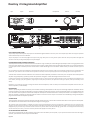
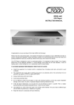
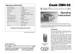
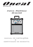
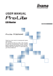
Destiny 2 Integrated Amplifier
Operating
Instructions
Thank you for purchasing the Destiny 2 Integrated Amplifier. You are now in possession of a State of the Art integrated amplifier. The functions and
operation of the Destiny 2 are very simple. However, the following notes are provided to explain all aspects of its design and use. Your Destiny 2
amplifier is designed to give you years of reliable use. If you need more assistance, it is always advisable to go back to the supplying dealer for his expert
help. If you are unfortunate enough to need service work to be carried out, the amplifier should be returned to your dealer in the original packing
material if possible.
The Destiny 2 amplifier is designed to work properly in normal domestic operating conditions. However, the amplifier's performance may be affected if
sited near to a radio transmitter such as a mobile phone etc. Re-siting the Destiny 2 amplifier or the radio transmitter will normalise the situation.
MAINS CONNECTION
After unpacking the Destiny 2 amplifier please keep the packing material in a safe place for possible future use. In the pack there is a separate mains
cable suitable for connecting to the mains supply in the country of use, stored in the cardboard inset section. The IEC socket end of the cable should be
firmly inserted into the connector on the rear panel marked "Mains Input".
Remember - do not overload the mains wall socket with too many plugs or adaptors. The high quality performance of the amplifier will be impaired if
the electrical supply to it is in poor condition. The "Mains Input" connection is also fitted with a fuse, specifically suited to the supply voltage of the
country of use. The correct value is clearly marked on the rear panel next to the Mains Input. Should it be necessary to replace the mains fuse, ensure
that you use the same type as specified on the rear panel, i.e. 5 x 20mm size, glass bodied cartridge type:
T 3.15 Amp surge resisting for 220-240V 50Hz AC,
T 6.3 Amp surge resisting for 110-120V 60Hz AC
T 8 Amp surge resisting for 100V (Japan)
POWER CONSUMPTION
It is appreciated by Hi-Fi enthusiasts that leaving equipment powered-up continuously can improve the performance. However, this small improvement
in sound quality comes at the expense of higher power consumption from the mains which will not only cost more but will also reduce the working life of
the Destiny 2. We recommend that if the equipment is not being used that you press Standby, which will reduce the consumption to less than 1 Watt. If the
equipment is not used for an extended period of time, it should be switched off from the mains switch on the rear panel or wall socket. Normal performance
can be achieved in a short period of time after switch-on.
POSITIONING
To obtain the best results, make sure the Destiny 2 amplifier is placed on a stable shelf or Hi-Fi equipment rack such as the Creek AR4. It is important to
allow adequate ventilation to the heat-sink in the centre of the amplifier, so avoid obstructing the ventilation slots on the top and bottom of the case. It
will be necessary to place the amplifier on its own shelf or the top of other equipment to allow for this.
OPERATING THE DESTINY 2 AMPLIFIER (QUICK SET-UP)
After first unpacking your amplifier, make sure the voltage matches the specification of the amplifier. There is a voltage selector switch on the underside
of the case. Turn the volume control to minimum (counter clockwise) when switching on and off to avoid sudden loud noises. Connect your source
component (CD player or Tuner) to one of the Line inputs on the back of the amplifier using a good quality stereo interconnect with RCA plugs at each
end. Right channel is on the bottom row of the RCA sockets. Connect both left and right speakers to the terminal posts on the back panel. Plug the mains
connector into the socket on the rear of the amplifier and into a suitable mains socket on the wall of your listening room. Switch on the power to the
amplifier using the switch next to the mains plug on the rear panel. 1 is ON and 0 is OFF. A blue LED will light above the Standby button. Press the Standby
button and the amplifier will wake up. The Standby LED will go off. The amplifier will now be ready to work. Select some music from the source and turn
the volume up to listen.
COMPREHENSIVE SET-UP
INPUT CONNECTION AND SWITCHING
The push button switches on the left-hand side of the front panel marked Input are used to select and listen to any of the desired inputs and switch the
pre-amp from passive to active. To select an input, press the up or down button to sequence through five inputs until you reach your choice, indicated
next to the blue LED that is lit. The separate button marked Tape overrides the other inputs, to allow the Destiny 2 to monitor the output of a tape
recorder. This can also be done by remote control.
The AV Direct input provides a signal straight to the power amp and can be used with a surround sound processor. This input caters specifically for those
people who are more than happy with their AV solution, but not happy with the stereo option. To connect from a processor, it is necessary to run an
interconnect cable from the front pre-amp output to the AV Direct input. The Destiny 2 then becomes a standalone power amplifier for front speaker
use in a 5.1 system. When the AV Direct input is selected in this configuration, the signal level of the Destiny 2 is no longer controlled by its volume knob.
It should be noted that when in AV Direct configuration, neither the Tape nor Active options can be used.
As all the line input sensitivities including Tape are the same, it is not necessary to use the precise input as described with the exception of AV. You may, for example,
plug a CD player into the Tuner input and obtain exactly the same result and performance as the dedicated CD input. However, for added flexibility, the first input
(Aux1) on the Destiny 2 amplifier can be configured either for Phono or Auxiliary line. To connect a turntable, it is necessary to first have an optional Creek Sequel
Phono plug-in board fitted. Alternatively Creek Audio produces the OBH-15 and OBH-18 stand alone Phono pre-amplifiers, plus the ‘high end’ Wyndsor Phono preamplifier, that should be connected to the Aux 1 input. Please check with your dealer. You can also write to [email protected] for further information.
Destiny 2 Integrated Amplifier
Tape
Inputs
Speakers
Headphones
Volume
Standby
Phones
Active
Power
Switch
AC Mains Input
& Mains Fuse
Speakers
A
Speakers
B
AV
Input
Pwr Amp Pre
In
Out
Tape Tape
Out In
Inputs
Ground
Post
PRE/ POWER CONNECTIONS
The pre-amp output and the power amp inputs are available through RCA sockets on the rear panel. This is helpful if you wish to bi-amp your speakers
with another Destiny 2 or drive a subwoofer.
The pre-amp output is not electrically buffered. Therefore running long cables from it or driving another product which has low input impedance will affect the
volume level and may also degrade the performance of the amplifier.
LOUDSPEAKER CONNECTION AND SWITCHING
The loudspeakers should be connected to the terminals marked 'A' using a suitable pair of cables designed specifically for audio use. High grade terminals
on the rear panel allow for plugs, spade lugs or bare wire to be connected. Tighten the terminal fully after fitting the speaker wire. To select Loudspeakers
A, use the push button on the front panel or remote handset. A blue LED will light next to the button. Please consult your dealer for advice if you are
unsure.
It is very important to connect the loudspeakers to the loudspeaker terminals in the correct phase. Cables are normally polarised with a line or a raised bump on the
positive side. If one channel is not connected in the same fashion as the other, a severe loss of bass performance and a spreading of the stereo image will result.
A second set of terminals marked 'B' allows the user to select from the Loudspeaker push buttons on the front panel. The options also include speakers
off (when using headphones), speakers A, speakers B or speakers A + B together. A blue LED will light next to the button in use.
It is NOT recommended to use loudspeakers of less than 4 Ohms resistance or more than two pairs of 8 Ohm speakers running in parallel from the amplifier at one
time. However, bi-wiring of one pair of speakers, using the four terminal posts per channel, can improve the sound of your system. (Consult your dealer for more
details).
Important - If it is necessary to move or change the location of the loudspeakers, make sure that you first switch off the amplifier from the mains, deselect the speakers, or select Standby.
HEADPHONES
There is a 1/4” (6mm) jack socket on the front panel to enable a wide range of headphones to be used, from low to high impedance. Remember that the
higher the impedance, the lower the level will be. To listen to headphones without the speakers, press the loudspeaker button in use with the LED lit next
to it. That will turn off the speakers and allow the headphones to always be used. Note that there is no delay to the switch on to headphone output, so
when the amplifier is switched out of Standby, keep the volume to a minimum. There may be a noise which can be avoided by pushing the headphone
plug into the socket after the amplifier is powered.
VOLUME LEVEL
The large volume control knob, situated on the right hand side of the front panel, is used to alter the relative level of the sound output from the amplifier.
Turn clockwise to increase the level. It does this by attenuating the incoming signal.
The maximum power of the amplifier is available only if the level of signal available from the line level equipment is sufficient to drive it to maximum power
(clipping). The volume control is necessary to adjust the overall level and relative level from one piece of equipment to another. It does not increase the power of the
amplifier and if it is found necessary to have the volume control set to a position which is considered to be high, (greater than 12 o’clock) before the desired level of
volume is obtained, do not worry, it does not necessarily mean that the amplifier has to work "flat-out".
ACTIVE AND PASSIVE OPERATION
If the source component does not have sufficient output level to drive the Destiny 2 to full power, or you require the volume control to be less high in
operation, press the button on the front panel marked Active.
Page Two
Destiny 2 Integrated Amplifier
ACTIVE AND PASSIVE OPERATION cont’d
This will introduce extra amplification (gain) into the pre-amplifier. In addition, the additional amplification is switchable in +3dB, +6dB and +9dB (x 1.5, x 2, x 3)
steps, selected by a slider switch on the bottom plate of the pre-amp section. Increasing the sensitivity (gain) does not make the amplifier more powerful.
Introducing gain will not improve the sound quality. The volume control will turn down automatically for 2 seconds when active is selected. This is to avoid a sudden
increase in sound level. You can adjust it to your preferred level after this.
It will be necessary to turn the amplifier upside down to make this change, so please make sure the amp is switched off from the mains supply first. The switch is
factory set in the +3dB position (centre). When placed upside down with the back of the amplifier closest to you, slide the switch to the left for +6dB gain, or to the
right for +9dB gain (6dB - 3dB - 9dB). The label next to the switch explains. It might be necessary to use a small screwdriver to help when moving the switch. If you
are in any doubt please consult your dealer.
LED INDICATORS AND POWERING ON
The Destiny 2 works differently to the original Destiny amplifier. Blue LEDs indicate when a function is in operation. When the Destiny 2 amplifier is first
switched on from the wall socket and rear panel switch, the blue Standby LED will light but the amplifier will effectively be switched off. The control
circuitry will be in Standby mode and will draw less than 1 Watt of power. Pressing the Standby button on the remote will not wake the amp up.
Wake up the Destiny 2 amplifier by pressing the Standby button on the front panel or any of the black amplifier specific buttons on the remote, with the
exception of the button labelled AMP. The Standby LED will flash for a short time and turn off. The selected input will then be indicated by a blue LED.
Remote volume changes will cause the Standby LED to flash. Pressing the Mute button on the remote handset will cause the Standby LED to flash while
it is in Mute. Pressing the Mute button again, or increasing the volume from the remote handset, will un-mute the amp and the Standby LED will stop
flashing and turn off. The amplifier will not be un-muted if the volume control is turned down from the remote handset. The amp can also be un-muted
from the front panel by pressing the Standby button once.
If the LED in the IR window turns red it indicates a serious fault and your amplifier may need to be returned to the supplying dealer for inspection.
PROTECTION MODES
The Destiny 2 amplifier has a sophisticated, computer controlled, protection mechanism against over-temperature, over current drive and output DC
offset.
Current Protection: If the speaker outputs are shorted while there is a signal playing, or if the speaker load impedance is too low (less than 4 Ohms) and the input
signal is too high, it may over-drive the amplifier. For a short period of time the amp will be muted. During this short period the Standby/Mute LED will flash.
Reducing the volume will normally restore correct operation. The Destiny 2 amp will automatically reduce the volume before un-muting the signal. If after 5
automatic reductions in volume the fault still persists, the Red protection LED will light in the crescent shaped window and the amplifier will be shut down. If this
happens check the wiring for shorts or other irregularities and re-boot the amplifier from the rear panel switch.
Thermal Protection: If the amplifier is driven hard for a long time and/or has insufficient ventilation, or if the ambient temperature is high, the signal will be
muted to enable the amp to cool down to an acceptable working temperature. During this period the Standby/Mute LED will flash and the input buttons sequence
up and down until the right temperature is restored.
DC Offset: If direct current is input to the Destiny 2 amplifier it will sense this and cause the output to be disconnected, to avoid damaging the loudspeakers. The
Standby LED and both Loudspeaker LEDs will flash until the fault is removed. In the unlikely event of a failure of the amplifier itself, the output and/or the mains supply
will be disconnected. This may require it to be returned to the dealer for servicing. Retain the packaging for this purpose if possible. If the fault is not removed in 10
seconds the red LED in the crescent window will light showing a serious fault and the amp will be locked. Check the source equipment for problems and re-boot the amp from the
mains switch on the rear panel.
REMOTE CONTROL
The SRC3 is a System Remote Control Handset designed to operate the new and old Creek Destiny and Evolution products. The SRC3
has several buttons that control future Creek products that will be redundant for the Destiny 2 amp. It can also operate older types of
Creek products. It allows the user to operate the volume control, input and speaker selection, active or passive pre-amp selection,
mute and display brightness. Some functions on the SRC3 are reserved for other Creek models and are not enabled on the Destiny 2,
such as balance and tone controls.
The coloured buttons allow the user to find the features dedicated to the device more easily. Press any of the amplifier specific black
buttons to operate the amplifier, blue buttons for the CD and green buttons for the tuner.
Several buttons have multiple functions to reduce the total number of buttons. This can be achieved by first pressing the product
button just below the circle of buttons in the middle, CD, Amp and Tuner. The remote will then be programmed to make the dark grey
buttons work for that device only, until another product button is pressed. So, if for example you want to select a specific track on the
CD player, press the Blue CD button, then the numeric button at the top. It is not necessary to press CD again if you want to select
another track.
If you want to select a specific amplifier input, press the black amp button and then the numeric button at the top which is marked
with the required input label above - i.e. Aux1, CD, Tuner, AV, Aux2 and Tape. The remote will continue to operate amp functions until
either CD or Tuner is pressed.
If you require the Tuner to go to a specific pre-set station, press the green Tuner button and then the desired pre-set number button.
All tuner function buttons are coloured green. The remote will continue to operate tuner functions until either Amp or CD is pressed.
Up and Down refers to CD track, amplifier input and tuner pre-set. Disp on the top right refers to Display and LED brightness for each
product. It is necessary to press one of the product buttons first before the Disp will work.
Scan forward and back also refers to CD and Tuner plus any future Creek amplifiers that might have a remote balance control.
Standby shuts down every device in the range that can go into Standby. N.B. Some Creek products so not have this feature. Please check the
appropriate manual. Waking up from Standby requires a button to be pressed for each product - i.e. wake up CD - press any CD button with the
exception of the CD product button as that only programmes the remote internally. Pressing the remote Standby button does not wake up the
product.
Page Three
Destiny 2 Integrated Amplifier
SPECIFICATION
Measured at 230V or 115V
Not recommended for use into more than 2 pairs of 8 Ohm speakers
Power Output into 8W
(2 channels) at rated mains voltage
Power Output into 4W
(2 channels)
Total Harmonic distortion (20 Hz to 20 kHz)
Frequency Response -1dB
-3dB
Slew Rate
Gain in passive pre-amp mode
Gain increase with active built in pre-amp
(Switchable voltage gain with slider switch under pre-amp section)
Input Sensitivity for 100W into 8W
Input Impedance of power amp section
Power Amp Output Impedance 100 Hz @1kHz)
Damping Factor
Pre-amp output level
Pre-amp output impedance controlled by volume pot
Signal to Noise Ratio ('A' weighted re 0 dB)
Separation (Crosstalk @ 1 kHz)
Maximum mains power consumption
Standby Power Consumption
Mains socket type
Loudspeaker outputs
Switchable mains voltage selector
Inputs (Aux input can be configured for a Creek Sequel phono plug in)
Input socket type (unbalanced)
Headphone output
Pre-amp output and power amp input connection
Weight (net)
Size (W x H x D) mm Including knob, terminals and feet
inches
Remote control
> 120 Watts
> 180 Watts
< 0.02%
1 Hz to 30 kHz
0.1 Hz to 65 kHz
> 50 V per µS
x48 or 33.6dB
0dB +3dB +6dB
+9dB
589mV 392mV 294mV 210mV
11 k Ohms
< 0.034 Ohms
> 235
Limited by volume control
0 - 20k Ohms
> 106 dB
> 69 dB
450 Watts
< 1 Watt
3 pin IEC, grounded
2pairs Switchable A+B
(8 x screw terminals)
115/230 V AC external
5 x line level plus tape
Gold plated RCA (Phono or cinch)
6.35mm (1/4”) Jack on front panel
Switchable on rear panel
10 kgs 22 lbs
430 x 80 x 355
16.9 x 3.14 x 13.98
Fully remote Creek SRC3 handset
MAINS VOLTAGE AND FREQUENCY IS INTERNALLY SET FOR THE COUNTRY OF USE
Creek Audio Ltd reserves the right to change or modify the specification of its products without prior warning
WARRANTY
If within two years of purchase date your Destiny product proves to be defective for any reason other than accident, misuse, neglect,
unauthorized modification, or fair wear and tear, Creek Audio Ltd. will, at its discretion, replace the faulty parts without charge for labour
or return carriage within the U.K.
This warranty is valid only in the U.K. and given in addition to statutory rights.
Service enquiries outside the U.K. should be addressed first to the supplying dealer and/or the Creek distributor/importer. Warranties
granted in these countries are entirely at the discretion of the distributor. Distributor information is available at www.creekaudio.com
Creek Audio Limited
12 Avebury Court, Mark Road, Hemel Hempstead HP2 7TA England
Telephone: +44 (0) 1442 260146 Fax: +44 (0) 870 622 0846
Email: [email protected]
Internet: www.creekaudio.com
E&OE