1
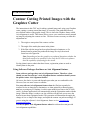
Tech-Neal-calities
Contour Cutting Printed Images with the
Graphtec Cutter
The instructions in this TNC are for taking a printed image and, using your Graphtec
cutter, cutting a contour around that image. It is usually a line path that follows a
user-defined outline of the graphic image. This is where the Graphtec feature called
Axis Alignment is useful. This feature allows you to cut a contour accurately around
an image by adjusting the contour cut line. The three factors necessary to make this
adjustment are:
1. The origin or start point of the contour cut line.
2. The angle of the media placement in the plotter.
3. If the film with the image has been placed through a laminator, or if a
thermal transfer printer has produced the image on vinyl, the stretch
factor has to be figured in.
Note: Depending on how the graphic was produced determines whether the
third factor needs to be considered. Also, only the FC4100 series plotters
have the capability of adjusting for the stretch.
For the plotter/cutter to obtain the three factors, registration points are used to
identify them in the print.
Using Software Packages that have an Axis Alignment feature.
Some software packages have an Axis Alignment feature. Therefore, when
should you use the software’s Axis Alignment feature and when should you use
the plotter/cutter Axis Alignment feature?
Of course, the choice is yours and depends upon what you are comfortable with.
However, here are some issues to consider.
Use your software Axis Alignment feature when the film has expanded or
retracted in size or shape due to lamination, or when printed by a thermal printer,
and you are using any of Graphtec’s earlier cutter models (previous to the FC4100
series). Software applications will automatically print the registration marks with the
image. When the image is ready to cut, the software will then ask you to move the
head to locate these registration marks. This operation will determine the angle, the
change of size or shape of the image, and adjust the contour cut path accordingly. If
you are using the software’s Axis Alignment, feature review “Locating the
Registration Points.”
Use the Graphtec Axis Alignment feature when the software does not provide
Axis Alignment capabilities.
Note: The information provided here is based on using the Graphtec Axis Alignment
feature. For using your software alignment feature, please refer to your software manual.
Preparing the Image for Contour Cutting
Preparing the image is important when using the Axis Alignment feature. Since, as
mentioned above, two to three points are needed, these must be printed within the
image. This can be accomplished several ways but we have found that the step by
step method shown below works the best.
After the graphic design has been created and the contour line is in place in the
graphic design software, draw and place a square box around the image. Be sure
there is a margin of at least ¼” between the image and the box.
The graphic design to be printed
Square box around the image
The final image, once printed should look like as follows:
Media
The graphic design to be printed
Square box around the image
The registration points can be selected by using the square box. For instance, the
origin or start point can be selected from the lower-left point of the square. The
diagram below shows the point that would be chosen using the Axis Alignment
function.
Remember where these points are when the plotter asks for these points at a later
time.
Note: Only the FC4100
Series will ask for the
third Axis point.
Axis point 2
Note: It should be noted
when the cutter adjusts
for the stretch, it needs
to know the original
distances between Axis
Point 1 and Axis Point 3, and the distance between Axis Point 1 and Axis Point
2. Be sure to measure these using the software measuring tool.
Axis Point 3:
Point for adjusting
Y-axis stretch
Axis Point 1:
Start or Origin Point
Locating the Registration Points
The method of locating the three points mentioned above: Axis point 1
(the start point), Axis point 2 (determining the angle), and possibly Axis
point 3 (determining the Y-axis stretch), is done with what is called a
locator device. There are three types of locators:
The bombsight is a magnified eyepiece that fits into the tool holder and
utilizes a crosshair for alignment. When using the bombsight to locate a
point, press the tool holder down so the tip of the bombsight touches the
film.
Using a pen. This is usually the least expensive way. When pressed down,
the pen makes a mark allowing you to see the position of the pen in
relation to the location of the registration points.
The last method, where a Light Point is used, is only available with the
FC4100 series. The Light Point will project a beam of light onto the vinyl
to help in locating the points. This is an easier method because it allows
you to see the positioning without having to bend over, as you do with the
bombsight and the pen methods.
Using the Cutter’s Axis Alignment Feature
Before Printing, confirm the following:
•
The image has been printed with a rectangle around the image, as discussed in
Preparing the Image for Contour Cutting.
•
The media with the image is placed in the plotter and the pinch rollers have
been lowered .
•
The plotter is in READY mode.
•
The locator has been placed in the tool holder. (See Locating the Registration
Points).
Using the Axis Alignment Feature
Review the instructions in your User’s manual on how to get to the Axis Alignment
option. Once there, it will ask for two to three points: AXIS POINT 1, AXIS POINT
2, and AXIS POINT 3 (if available).
When each AXIS POINT is asked for, use the arrow keys to position the locator to
the first point. To orient you to each point’s location, look at the example we used
previously, except in this case the media is positioned in the plotter
Plotter/Cutter
Axis Point 3:
Axis Point 1
Axis point 2
Note: If you are using the pen or the bombsite for a locator, when approaching the
different points be sure to press the tool holder down to the film.
Note: If the image on the film is too large so that part of the image runs under the
wheels, refer to the section Moving the Pinch Roller to Your Advantage in TNC Good Tracking From Your Cutter
Note: With some software applications, when printing an image that is destined to be
contoured cut, it will ask for points that are on the image. This will enable it to
adjust the contour cut line to the printed image (See When To Use The Software
Applications Axis Alignment)
Tip: You may desire the contour line to be offset from the border of your image. This
will leave a white margin around the image.
However, in many cases you may desire to have the image cut without a white
margin. If this is the case, have your software put a bleed on the image. This is
where the border of the image will extend or bleed the color out beyond its normal
border. Whereas the contour cut line will still be the original border, removing the
chances of a slim margin of white margin showing through.