1
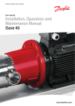
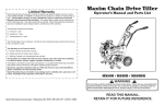
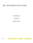
MULTISTACK
WATER COOLED CONDENSING UNIT
INSTALLATION and USER MANUAL
Multistack
1065 Maple Ave PO Box 510
Sparta, WI 54669
Phone: 608-366-2400 Fax 608-366-2450
For Models:
MS20C, MS30C,
MS50Z
MULTISTACK Water Cooled Condensing Unit
Installation Manual Supplement
Models: MS20C, MS30C (shown)
MS50Z, MS50B
Note: This document is to be used as a supplement to the Water Cooled Chiller
Installation Manual. All installation details including placement of the modules,
clearance recommendations, Victaulic connections, and condenser side care should
be followed from that manual.
The Multistack Water Cooled Condensing Unit is a 2 circuit module used in
conjunction with a remote DX coil to provide cooling to an external source. Unlike
Multistack Water Cooled Chillers, the Condensing Unit is not controlled by one
central master control. Each module is controlled by it’s module sensor board
which uses a customer supplied input to stage each compressor.
ADDITIONAL MODULE COMPONENTS (1 per circuit):
• Suction Accumulators
• Suction Filter Drier with Shut off Valves
• Liquid Shut off Valves
• Discharge Check Valves
MODEL NUMBER:
MS30C5H2D
MULTISTACK Water Cooled Condensing Unit
Installation Manual Supplement
Models: MS20C, MS30C (shown)
MS50Z, MS50B
The following information details what is supplied with the Condensing Unit and what is
not. Any shortages of supplied components should be noted with the freight company at
delivery and reported to Multistack at that time.
EXTERNAL COMPONENTS SUPPLIED WITH UNIT:
• Liquid Line Solenoid Valves:
• Liquid Line Filter Driers:
• Liquid Receiver Tank:
• Pressure Relief Valves:
• Receiver King Valves:
Qty 1 per circuit
Qty 1 per circuit
Qty 1 per circuit
Qty 1 per circuit
Qty 2 per circuit
COMPONENTS SUPPLIED
WITH UNIT
REQUIRED COMPONENTS NOT SUPPLIED WITH UNIT:
• Metering Device (Thermal Expansion Valve)
• Liquid Line Sight Glass
• DX Coil
MULTISTACK Water Cooled Condensing Unit
Installation Manual Supplement
Models: MS20C, MS30C (shown)
MS50Z, MS50B
ELECTRICAL CONNECTIONS:
Please see the Water Cooled Chiller Installation Manual for the bussbar high voltage
connections.
The control contractor must run connections to each modules module sensor board (see
adjacent). Connections for the “A” compressor should be made at TB-8 #1-2. For the
“B” compressor TB8 # 1-3. Use 16 AWG wire as minimum.
The liquid line solenoid valves which are supplied by Multistack and installed external to
the condensing unit must be connected to each condensing unit’s electrical back-plate.
This is a 24V connection and should be wired by the control contractor with 16 AWG
minimum (please see adjacent, also the electrical drawings for more detail).
SINGLE MOD. CTRL. BOARD
CONTROL PANEL BACKPLATE
MULTISTACK Water Cooled Condensing Unit
Installation Manual Supplement
Models: MS20C, MS30C (shown)
MS50Z, MS50B
TERMINAL CONNECTIONS
PIPING CONSIDERATIONS:
All piping from the modules to the DX coil must be properly sized and adequately
supported. In addition the selection of properly sized coils, metering devices and airflow
across the coils is imperative to system performance. A maximum distance of 150 feet
from the condensing unit to the coil is highly recommended. Please see below for
recommended pipe sizes
Module
MS20C
MS30C
MS50Z/B
LIQUID LINE SIZES
50’
75’
100’
¾”
¾”
¾”
7/8” 7/8” 7/8”
1 1/8” 1 1/8” 1 1/8”
125’
¾”
7/8”
1 1/8”
150’
¾”
7/8”
1 1/8”
Psi Drop
.5 – 3.5
.5 – 3.0
.5 – 2.5
Module
MS20C
MS30C
MS50Z/B
SUCTION LINE SIZES
50’
75’
100’ 125’
1 3/8” 1 3/8” 1 5/8” 1 5/8”
1 5/8” 1 5/8” 1 5/8” 2 1/8”
2 1/8” 2 1/8” 2 1/8” 2 1/8”
150’
1 5/8”
2 1/8”
2 1/8”
Psi Drop
1.5 – 2.0
1.5 – 1.0
1.0 – 2.5
MULTISTACK Water Cooled Condensing Unit
Installation Manual Supplement
Models: MS20C, MS30C (shown)
MS50Z, MS50B
PIPING AND COMPONENT LOCATION:
The Liquid Receivers and Valves, Liquid Filter Drier, Liquid Line Solenoid Valves, and
Pressure Relief Valves are all supplied with the Unit but must be installed remotely.
Correct sizing of the receivers is very important as the DX modules do incorporate a
pump-down cycle. The receiver must hold 80% of the system charge and should be sized
by the engineer before the modules and components are shipped. All connections should
be brazed or silver soldered with good piping practices and Nitrogen purging being used
(Please see the diagram on page 6 for component location).
Evacuation of each circuit to a maximum of 500 microns holding for 15 minutes should
be achieved prior to start up and before the module is charged with refrigerant. The
correct method of charging the circuit is by using a pre-determined calculated weigh in
charge. Refrigerant charging can be done at the time of start up or ahead of time by a
qualified technician. Charge as much liquid as possible directly into the receiver. If
water is present in the condenser during charging, to prevent any possible freeze
condition make sure the condenser pump is turned on and water is flowing through the
condenser heat exchanger. Depending on the location of the liquid line sight glass and
it’s proximity to any elbows in the piping you may see refrigerant flashing during normal
operation even though the circuit is properly charged.
Once the installation is complete, the pre-start up checklist (see following pages) should
be completed and sent to your Multistack Representative. The Multistack Representative
will then assist in scheduling start up of the modules.
CONTROL:
The control of the Modules is determined by the external input to each modules Single
Module Control Board . Compressors will stage on and off based on this signal.
OUTPUTS:
Each Modules Single Module Control Board has a Condenser Pump Relay (CPR) on
terminals 4-5 and a Cooling Alarm Relay (CAR) on terminals 4-6 of TB-8. Each Relay
will send a 24V signal. The CPR anytime 1 or more compressors are on and the CAR
anytime 1 or more compressors is in fault.
MULTISTACK Water Cooled Condensing Unit
Installation Manual Supplement
Models: MS20C, MS30C (shown)
MS50Z, MS50B
SAFETIES:
High Pressure Switch: Cuts out at 300 psig for R22 and 320 psig for R-407C. Requires
manual reset on switch. D9 indicator light on Single Module Control Boardl will be lit
when in fault.
Low Pressure Switch: Cuts out at 10 psig. Requires manual reset on switch. D9
indicator light on Single Module Control Board will be lit when in fault.
PUMPDOWN:
Each Circuit is equipped with refrigerant pump down during the off cycle. If the pressure
in the compressor gets above 65 psig, the compressor turns on and pumps refrigerant
through the condenser and into the receiver until the pressure drops to 35 psig and cuts
out. The liquid line solenoid will remain closed during this process.
SINGLE MODULE CONTROL BOARD:
The Control Board contains the TB8 terminal strip for termination of the compressor
start controls as well as the Condenser Pump Relay and Cooling Alarm Relay. In
addition the board has an ON/OFF switch that will disable the module, and a Manual
Reset Button that must be cleared for operation. The board is protected by a .5 amp fuse
and also contains 6 LED’s. The LED functions are explained below.
LED
D6
D7
D8
D9
D20
D21
Identifies
Compressor “A” status
Compressor “B” status
Power
Fault
Condenser Water
Chilled Water
Description
Lit when compressor is on
Lit when compressor is on
Lit when board is powered
Lit when a fault is present
not used on DX modules
not used on DX modules
MULTISTACK Water Cooled Condensing Unit
Installation Manual Supplement
Models: MS20C, MS30C (shown)
MS50Z, MS50B
PLEASE SEE PAGE 13 OF THE WATER COOLED CHILLER INSTALL MANUAL
FOR BUSSBAR INSTALLATION
• Optional Single Module High Voltage Connection Shown below.
DX Installation Checklist and Request for Authorized Start-Up
Engineer
Customer:
Job Name:
Job Location:
Job Number:
. The service of a
The work (as checked below) is in process and will be completed by: Date
Multistack Authorized Start-up Engineer is requested on this date and it is understood that if the work
checked below is not completed, the engineer’s time and expense will be billed to us by Multistack. Terms
Net 30 days. Multistack is to be notified at least ten (10) working days in advance of the start-up
date.
CONDENSER WATER
Piping complete and connected to Multistack Units.
Water system filled and vented
Pumps installed (rotation checked)
Recommended strainers installed
Water system operated and flow meets design
Strainers checked for debris
Flow or differential pressure switch installed
Condenser Water sensor wells installed
Yes
Yes
Yes
Yes
Yes
Yes
Yes
Yes
No
No
No
No
No
No
No
No
N/A
N/A
N/A
N/A
N/A
N/A
N/A
N/A
DX COIL
Refrigerant Piping complete and connected to modules
Piping in accordance with good engineering practice
Receiver, Liquid line filter drier, & sight glass installed
Metering device, & Liquid line solenoid valve installed
System evacuated to 500 microns or less
System charged with refrigerant
Yes
Yes
Yes
Yes
Yes
Yes
No
No
No
No
No
No
N/A
N/A
N/A
N/A
N/A
N/A
ELECTRICAL
Power wiring complete and in accordance with nameplate
rating on unit and prepared for connection in accordance
with installation manual
Note: No power is to be applied prior to inspection by start-up engineer
Interlock wiring complete between control panel
MISCELLANEOUS
Thermometers, gauges, controls installed
A minimum system load of 50% is available for testing
Yes
No
N/A
Yes
No
N/A
Yes
Yes
No
No
N/A
N/A
We understand that authorized representatives of the installing electrical and piping contractor must be available
during the start up period and that coordination is our responsibility.
We understand that the services of the Start-up Engineer will be furnished for a period of not more than sixteen (16)
consecutive normal working hours and we agree that a charge for time and expenses will be made by Multistack if
services are required longer.
Signed
Phone number
Company
DX START-UP DATA LOG
START-UP DATE:
SHIP DATE:
JOB NAME:
JOB NUMBER:
ADDRESS:
MULTISTACK REPRESENTATIVE:
MODEL NUMBER:
*** MODULE SERIAL NUMBERS ***
1.
2.
3.
4.
5.
6.
WATER SIDE AND MODULE CHECKLIST
CIRCLE CORRECT RESPONSE
1. Condensing Unit mounted on rails and isolators?
YES
NO
2. Any visible damage?
YES
NO
If yes, detail:
3. Any obvious oil and/or refrigerant leaks?
YES
NO
If yes, detail:
4. All pipe work independently supported from Unit?
YES
NO
5. System CW strainer installed?
YES
NO
EXTERNAL AND DX CHECKLIST (Check if Applicable)
1. Components Installed: Receivers
LL Solenoid Valves
Pressure Relief Valves
Liquid Line Filter Drier
2. Liquid Line size
Suction Line size
3. Refrigerant charge per circuit
Refrigerant type
Metering Devices
Liquid Sight Glasses
ELECTRICAL AND CONTROLS CHECKLIST
1. All electrical connections tight and correct?
2. Power wiring sufficient to carry F.L.A.?
3. Voltage levels: PHASES 1 + 2 _______ 2 + 3 _______
_______ 3 + G _______
4. Total AMP draw at 100% capacity: _________AMPS
5. Leave system in full operation?
6. Notify contractor of any problems?
Start-up Service Technician
YES
NO
YES
NO
1 + G _______ 2 + G
YES
YES
NO
NO
Owner or Contractor
Acceptance
DX START-UP DATA LOG
SYSTEM: CW Pressure Drop
COMPRESSOR CONTROL:
psi
External Safeties?
MODULE
CIRCUIT
A
1.
B
A
2.
B
3.
A
B
A
4.
B
5.
A
B
6.
A
B
MISC. NOTES:
CW OUT
°F
.
.
.
CURRENT
A
°F
(type)
(offset?)
LP Switch setting
.
SAFETIES: HP Switch setting
PUMPDOWN: Setting
CW IN
B
Super
C
heat
DISCH
P sig
SUCT
Psig