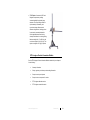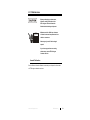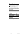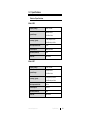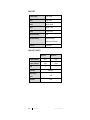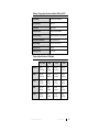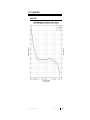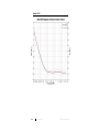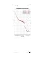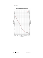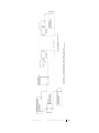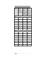
1
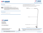
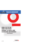
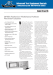
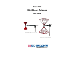
® E stablished 1981 Advanced Test Equipment Rentals www.atecorp.com 800-404-ATEC (2832) 6500 Series Loop Antennas User Manual ETS-Lindgren Inc. reserves the right to make changes to any product described herein in order to improve function, design, or for any other reason. Nothing contained herein shall constitute ETS-Lindgren Inc. assuming any liability whatsoever arising out of the application or use of any product or circuit described herein. ETS-Lindgren Inc. does not convey any license under its patent rights or the rights of others. © Copyright 2013 by ETS-Lindgren Inc. All Rights Reserved. No part of this document may be copied by any means without written permission from ETS-Lindgren Inc. Trademarks used in this document: The ETS-Lindgren logo is a trademark of ETS-Lindgren Inc. Revision Record MANUAL,6500 SERIES LOOP ANTENNAS | Part #399293, Rev. A ii Revision Description Date A Initial Release November, 2013 www.ets-lindgren.com Table of Contents Notes, Cautions, and Warnings ................................................ v 1.0 Introduction .......................................................................... 7 Model 6502 ................................................................................................. 8 Model 6507 ................................................................................................. 8 Model 6509 ................................................................................................. 9 Models 6511 and 6512 ............................................................................... 9 Standard Configuration ............................................................................. 10 Optional Items .......................................................................................... 10 Carrying Cases ................................................................................. 10 Tripod Options .................................................................................. 10 ETS-Lindgren Product Information Bulletin ............................................... 11 2.0 Maintenance ....................................................................... 13 Annual Calibration .................................................................................... 13 Replacement and Optional Parts .............................................................. 14 Service Procedures .................................................................................. 14 3.0 Specifications ..................................................................... 15 Electrical Specifications ............................................................................ 15 Model 6502 ....................................................................................... 15 Model 6507 ....................................................................................... 15 Model 6509 ....................................................................................... 16 Models 6511 and 6512...................................................................... 16 Battery Charger Specifications: Models 6502 and 6507 ............................ 17 Physical Specifications: All Models ........................................................... 17 4.0 Mounting Instructions ....................................................... 19 Additional Mounting Options ..................................................................... 19 4-TR Mounting Options ..................................................................... 19 7-TR and Mast Mounting Options...................................................... 20 2x2 Boom Mounting Options ............................................................. 21 5.0 Operation ............................................................................ 23 Front Panel Indicator Lights: Models 6502 and 6507................................. 23 Battery Charger: Models 6502 and 6507 ................................................... 24 www.ets-lindgren.com iii Features and Components ................................................................ 24 Fast Charge and Trickle Charge Modes ............................................ 25 6.0 Typical Data ........................................................................ 27 Model 6502 ............................................................................................... 27 Model 6507 ............................................................................................... 28 Model 6509 ............................................................................................... 29 Model 6511 ............................................................................................... 30 Model 6512 ............................................................................................... 31 7.0 Radiation Pattern ............................................................... 33 Typical Radiated Pattern for an Electrically Small Loop ............................ 34 Appendix A: Warranty ............................................................. 35 Appendix B: 6505 Shielding Effectiveness Test Kit ............. 37 Measuring Magnetic Shielding Effectiveness ............................................ 37 Shielding Effectiveness Measurements for Magnetic Field ........................ 40 Appendix C: EC Declaration of Conformity .......................... 43 Model 6502 ............................................................................................... 43 Model 6507 ............................................................................................... 44 iv www.ets-lindgren.com Notes, Cautions, and Warnings Note: Denotes helpful information intended to provide tips for better use of the product. Caution: Denotes a hazard. Failure to follow instructions could result in minor personal injury and/or property damage. Included text gives proper procedures. Warning: Denotes a hazard. Failure to follow instructions could result in SEVERE personal injury and/or property damage. Included text gives proper procedures. See the ETS-Lindgren Product Information Bulletin for safety, regulatory, and other product marking information. www.ets-lindgren.com v This page intentionally left blank. vi www.ets-lindgren.com 1.0 Introduction The ETS-Lindgren 6500 Series Loop Antennas include both active and passive antennas. Loop antennas provide a wide range of magnetic field testing. Some models include active electronics for amplification and impedance matching, consistent linear antenna factors, and signal attenuation. Most include a balanced Faraday shield to reduce response to E-fields for pure magnetic field measurements. Whether used individually or as a set, the loop antennas provide an efficient and economical solution to magnetic field measurement. For information on Model 6505 Shielding Effectiveness Test Kit, see page 37. Each antenna is individually calibrated in accordance with the IEEE Std 291, using National Institute of Standards and Technology (NIST) traceable equipment. By knowing the actual antenna factors and performance characteristics instead of typical data, you can more accurately measure field strength in your tests. Each antenna includes actual individual calibration factors and signed Certificate of Calibration Conformance. All loop antennas are constructed of lightweight aluminum, which provides durability and reliability for years of trouble-free indoor and outdoor services. The base of each loop antenna provides a standard 1/4–20 threaded connector for mounting to an ETS-Lindgren tripod or other tripod. For the variety of mounting options available, see Mounting Instructions on page 19. www.ets-lindgren.com Introduction 7 Model 6502 The Model 6502 Loop Antenna is an active receiving loop antenna designed to perform commercial emissions standards testing, and can be used for any magnetic testing. The Model 6502 has a frequency range of 9 kHz to 30 MHz. A radio frequency preamplifier is built into the base of the antenna and provides a 50 Ω output which is used by a receiver. The preamplifier helps produce good sensitivity and almost constant antenna factors. Power for the preamplifier is supplied by rechargeable, sealed lead-acid batteries; a battery charger is included. The charger is switch selectable for 115 VAC/230 VAC, and operates at 50 Hz/60 Hz. For more information on the battery charger, see page 17. Model 6507 The Model 6507 Loop Antenna is an active receiving loop antenna designed to perform shielding effectiveness measurements per MIL-STD 285 and NSA-65-6 specifications. The Model 6507 has a frequency range of 1 kHz to 30 MHz. A radio frequency preamplifier is built into the base of the antenna designed for use with most 50 Ω receivers. Power for the preamplifier is supplied by rechargeable, sealed lead-acid batteries; a battery charger is included. The charger is switch selectable for 115 VAC/230 VAC, and operates at 50 Hz/60 Hz. For more information on the battery charger, see page 17. 8 Introduction www.ets-lindgren.com Model 6509 When using the Model 6509 as a transmitting device, reduce amplifier power to zero Watts before band switching. The Model 6509 Passive Loop Antenna is designed for shielding effectiveness and immunity testing. The Model 6509 operates in the frequency range of 1 kHz to 30 MHz. The base contains a Type N female connector and a selectable four-band RF transformer. The RF transformer gives the Model 6509 greater efficiency, which results in a better conversion of input power to field strength. Models 6511 and 6512 The Model 6511 and Model 6512 are passive loop antennas; the Model 6511 is designed for low frequencies and covers the 20 Hz to 5 MHz range, and the Model 6512 covers the 9 kHz to 30 MHz range. www.ets-lindgren.com Introduction 9 Standard Configuration Antenna/coil assembly Mounting base that accepts an ETS-Lindgren tripod or other tripod mount with standard 1/4–20 threaded hardware Battery charger (included only with Model 6502 and Model 6507) Optional Items CARRYING CASES A custom carrying case is available for some of the loop antenna models. For more information, contact ETS-Lindgren. TRIPOD OPTIONS ETS-Lindgren offers the following non-metallic, non-reflective tripods for use at both indoor and outdoor EMC test sites. 4-TR Tripod—Constructed of linen phenolic and delrin, designed with an adjustable center post for precise height adjustments. Maximum height is 2.0 m (80.0 in), and minimum height is 94 cm (37.0 in). This tripod can support up to an 11.8 kg (26.0 lb) load. 10 Introduction www.ets-lindgren.com 7-TR Tripod—Constructed of PVC and fiberglass components, providing increased stability for physically large antennas. The unique design allows for quick assembly, disassembly, and convenient storage. Allows several different configurations, including options for manual or pneumatic polarization. Quick height adjustment and locking wheels provide ease of use during testing. Maximum height is 2.17 m (85.8 in), with a minimum height of 0.8 m (31.8 in). This tripod can support a 13.5 kg (30 lb) load. ETS-Lindgren Product Information Bulletin See the ETS-Lindgren Product Information Bulletin included with your shipment for the following: Warranty information Safety, regulatory, and other product marking information Steps to receive your shipment Steps to return a component for service ETS-Lindgren calibration service ETS-Lindgren contact information www.ets-lindgren.com Introduction 11 This page intentionally left blank. 12 Introduction www.ets-lindgren.com 2.0 Maintenance Before performing any maintenance, follow the safety information in the ETS-Lindgren Product Information Bulletin included with your shipment. WARRANTY Maintenance of the 6500 Loop Antennas is limited to external components such as cables or connectors. Warranty may be void if the housing is opened. If you have any questions concerning maintenance, contact ETS-Lindgren Customer Service. Annual Calibration See the Product Information Bulletin included with your shipment for information on ETS-Lindgren calibration services. www.ets-lindgren.com Maintenance 13 Replacement and Optional Parts ETS-Lindgren may substitute a similar part or new part number with the same functionality for another part/part number. Contact ETS-Lindgren for questions about part numbers and ordering parts. Following are the part numbers for ordering replacement or optional parts for the Model 6500 Series Loop Antennas. Part Description Part Number 4-TR Tripod Positioner 4-TR 7-TR Tripod Positioner 7-TR Battery Charger for Model 6502 and Model 6507 102615 Carrying Case with Foam, Model 6502 6502CASE W/FOAM Service Procedures For the steps to return a system or system component to ETS-Lindgren for service, see the Product Information Bulletin included with your shipment. 14 Maintenance www.ets-lindgren.com 3.0 Specifications Electrical Specifications MODEL 6502 Frequency Range: Dynamic Range: Sensitivity (Typical): 9 kHz—30 MHz 85 dB at 10 kHz 125 dB at 1 MHz -1 dB (uA/m) at 10 kHz -42 dB (uA/m) at 1 MHz 1 dB Compression Point: 5 V/m Power Required: Battery-operated Impedance (Nominal): 50 Ω Connector: BNC female MODEL 6507 Frequency Range: Dynamic Range: Sensitivity (Typical): 1 dB Compression Point: Power Required: 1 kHz—30 MHz 76 dB at 10 kHz 116 dB at 1 MHz 11 dB (mA/m) at 10 kHz -29 dB (mA/m) at 1 MHz 10 V/m 13.8 VDC Impedance (Nominal): 50 Ω Connector: BNC female www.ets-lindgren.com Specifications 15 MODEL 6509 Frequency Range: 1 kHz—30 MHz Band 1: 1 kHz—60 kHz Band 2: 60 kHz—400 kHz Band 3: 400 kHz—1 MHz Band 4: 1 MHz—30 MHz Maximum Input Power: 1 kW Impedance (Nominal): Varies with frequency (calibrated in a 50 Ω system) Connector: Type N female MODELS 6511 AND 6512 Model 6511 Frequency Minimum: 20 Hz 9 kHz Frequency Maximum: 5 MHz 30 MHz 8 1 Turns Connectors: 16 Model 6512 BNC female Maximum Input Power: 20 W Polarization: Linear Specifications www.ets-lindgren.com Battery Charger Specifications: Models 6502 and 6507 Input Voltage: 115/230 VAC selectable Input Frequency: 50/60 Hz Input Power: 20 VA max Protection Class: Class II double insulated Input Fuse Rating: 200 mA time-delay, Type 5x20 mm Input Power Connection: IEC-320 power inlet Output Voltage: 12 VDC (13.5–15 VDC) Output Current: 350 mA Safety Approvals TUV, CSA Physical Specifications: All Models 6511 / 6512 6502 6507 6509 Diameter: 56 cm (22.05 in) 60 cm (23.62 in) 30.4 cm (11.97 in) 30.4 cm (11.97 in) Height: 59.8 cm (23.54 in) 67.3 cm (26.50 in) 37.8 cm (14.88 in) 47.8 cm (18.82 in) Length: 3.8 cm (1.50 in) 12 cm (4.72 in) 12 cm (4.72 in) 7.6 cm (2.99 in) Width: 12.7 cm (5.0 in) 19 cm (7.48 in) 19 cm (7.48 in) 8 cm (3.15 in) Weight: 1.6 kg (3.53 lb) 2 kg (4.41 lb) 1.8 kg (3.97 lb) 1.3 kg (2.87 lb) www.ets-lindgren.com Specifications 17 This page intentionally left blank. 18 Specifications www.ets-lindgren.com 4.0 Mounting Instructions Each loop antenna is a precision measurement device. Handle your antenna with care. Additional Mounting Options 4-TR MOUNTING OPTIONS The 6500 Series Loop Antennas mount directly to an ETS-Lindgren 4-TR Tripod; no additional hardware is required. www.ets-lindgren.com Mounting Instructions 19 7-TR AND M AST MOUNTING OPTIONS Following are options for mounting the 6500 Series Loop Antennas onto an ETS-Lindgren 7-TR Tripod or mast. Contact the ETS-Lindgren Sales Department for information on ordering optional mounting hardware. Mast refers to 2070 Series, 2075, and 2175 Antenna Towers. 7-TR refers to these booms: 109042 boom—Straight boom; for general antenna mounting on a 7-TR 108983 boom—Offset boom; for general antenna mounting on a 7-TR with pneumatic or manual polarization; can also be used to mount stinger-type antennas 118947 boom—For stinger-type antennas only 108507 boom—Centerline rotation boom for Model 3106 Series antennas only; when changing polarization, maintains centerline rotation 20 Mounting Instructions www.ets-lindgren.com 2X2 BOOM MOUNTING OPTIONS 2x2 boom refers to a typical 2-inch by 2-inch boom. Following are additional options for mounting the 6500 Series Loop Antennas onto a 2x2 boom. Contact the ETS-Lindgren Sales Department for information on ordering optional mounting hardware. www.ets-lindgren.com Mounting Instructions 21 This page intentionally left blank. 22 Mounting Instructions www.ets-lindgren.com 5.0 Operation Before connecting any components or placing into operation, follow the safety information in the ETS-Lindgren Product Information Bulletin included with your shipment. When using the Model 6509 as a transmitting device: Reduce amplifier power to zero watts before band switching, and then select the frequency band by rotating the band switch. To calculate the field strength: Signal Level + Cable Loss + Antenna Factor = Relative Field Strength Cable loss should be measured periodically for each cable used in testing. Front Panel Indicator Lights: Models 6502 and 6507 Saturation Indicator—Illuminates when input signal intensity exceeds the 1 dB compression level of 5 volts per meter (Model 6502) to 10 volts per meter (Model 6507), and will remain illuminated for about 1 second. Power Indicator—Illuminates to show that the loop is on and functional. When the charge on the battery decreases to the point that the antenna calibration is no longer valid, the LED will go dark. However, the antenna will still function and provide reasonable output signals until the batteries are spent. www.ets-lindgren.com Operation 23 Battery Charger: Models 6502 and 6507 The Model 6502 and Model 6507 are powered by two 6-VDC, sealed lead-acid batteries. The included battery charger is intended for charging only the sealed lead-acid batteries in ETS-Lindgren products. The Model 6502 is not designed to operate using the battery charger as a power source. When the batteries are completely discharged, charging time is approximately eight hours. Batteries should provide power for approximately 16 hours before recharging is required. FEATURES AND COMPONENTS Voltage selection switch—The battery charger is voltage-selectable, providing the necessary charge voltage and current from either a 115 or 230 VAC 50/60 Hz source. The voltage selection switch is located next to the power input receptacle. Select the proper input voltage before connecting the battery charger to the power mains. Power On—Illuminates when the charger is plugged into an AC outlet. Battery charging port—Located on the front of the unit. Always remove main power before opening the battery charger case. 24 Fuse—A 200 mA 250 VAC time-delay fuse protects against overcurrent. When replacing the fuse, use a fuse of the same type and rating to maintain safe operations; see the battery charger specifications on page 17 for more information. The fuse is accessible by removing the two Phillips head screws on the bottom of the unit. Operation www.ets-lindgren.com Power cord—To maintain safety requirements, use the safety-approved power cord provided. If you use another method to attach the battery charger to the power mains, use only a type HD21 (PVC cord) or type HD22 (rubber cord) with a nominal cross-section of 2 0.75 mm . FAST CHARGE AND TRICKLE CHARGE MODES The battery charger provides both fast and trickle charge operation. Switching from one charge mode to the other occurs automatically. Fast Charge mode—The battery charger is in fast charge mode when the Fast Charge LED is illuminated. This LED illuminates when the battery is charging, and becomes darker or blinks when the battery is fully charged. When the battery charger completes the fast charge cycle, it will automatically switch to trickle charge mode. Trickle Charge mode—The battery charger is in trickle charge mode when the Power On LED is illuminated and the Fast Charge LED is dark. When not in use, connect the loop antenna to the battery charger in trickle charge mode. www.ets-lindgren.com Operation 25 This page intentionally left blank. 26 Operation www.ets-lindgren.com 6.0 Typical Data Model 6502 www.ets-lindgren.com Typical Data 27 Model 6507 28 Typical Data www.ets-lindgren.com Model 6509 www.ets-lindgren.com Typical Data 29 Model 6511 30 Typical Data www.ets-lindgren.com Model 6512 www.ets-lindgren.com Typical Data 31 This page intentionally left blank. 32 Typical Data www.ets-lindgren.com 7.0 Radiation Pattern The 6500 Series Loop Antennas are electrically small loops (size is small in wavelengths), giving them identically-shaped radiation patterns. Each loop operates at a frequency under 30 MHz. At 30 Hz the wavelength is 10 m; the largest loops have a circumference of 1.88 m (C=πD), which is much smaller than the wavelength. For electrically small loops it can be assumed that the current on the loop is constant. If we place the loop on the plane z=0 so that the z-axis is perpendicular to the plane of the loop and following the derivation presented by Balanis in Antenna Theory: Analysis and Design (2nd Ed. John Wiley and Sons: New York 1997), it follows that the radiated magnetic fields are given by: [ ( ) ] [ ( ) ] And the radiated electric fields are given by: ( www.ets-lindgren.com ) [ ] Radiation Pattern 33 Typical Radiated Pattern for an Electrically Small Loop The following illustrates the typical radiated pattern for an electrically small loop. 34 Radiation Pattern www.ets-lindgren.com Appendix A: Warranty See the Product Information Bulletin included with your shipment for the complete ETS-Lindgren warranty for your 6500 Series Loop Antenna. DURATION OF WARRANTIES FOR 6500 SERIES LOOP ANTENNA All product warranties, except the warranty of title, and all remedies for warranty failures are limited to two years. Product Warranted Duration of Warranty Period Model 6502 Loop Antenna Model 6507 Loop Antenna Model 6509 Passive Loop Antenna 2 Years Model 6511 Shielded Loop Antenna Model 6512 Shielded Loop Antenna www.ets-lindgren.com Warranty 35 This page intentionally left blank. 36 Warranty www.ets-lindgren.com Appendix B: 6505 Shielding Effectiveness Test Kit The ETS-Lindgren Model 6505 Loop Shielding Effectiveness Test Kit is a set of loop antennas that includes the following: Model 6507 Active Receiving Loop Antenna Model 6509 Passive Loop Antenna Battery Charger Measuring Magnetic Shielding Effectiveness 1. Set the transmitting and receiving antennas apart at a distance equal to 24 inches plus the thickness of screen room. 2. Set up equipment as shown in the diagram on page 39. 3. Turn generator to on position. 4. Disable RF output of generator. 5. Turn amplifier to on position. 6. Turn receiver to on position. 7. Turn receiver loop power on, and verify light is on. 8. Set desired frequency on generator. Set the same frequency on receiver. 9. Set the attenuator at maximum (100–120 dB) attenuation. 10. Enable RF output of the generator. www.ets-lindgren.com 6505 Shielding Effectiveness Test Kit 37 11. Adjust signal amplitude on signal generator to maximum allowed by amplifier input. Establish a reference level by decreasing the attenuation level unit the signal can be detected by the screen room wall between them. Reduce attenuation further until signal is again seen at the same level as without shielding. The difference in the two attenuator settings is the shielding effectiveness. If the signal cannot be seen with a zero setting, then the shielding effectiveness is greater than the attenuation range, or the power amplifier does not have enough power. The shielding effectiveness readings are valid only if the power amplifier is operating in the linear region. This can be verified by reducing (or increasing) attenuation and observing the receiver signal on the analyzer or receiver. If the receiving signal also decreases (or increases) by the same amount, then the amplifier is operating in the linear region. Reference: 38 MIL-STD 285 NSA 65-6 6505 Shielding Effectiveness Test Kit www.ets-lindgren.com www.ets-lindgren.com 6505 Shielding Effectiveness Test Kit 39 Shielding Effectiveness Measurements for Magnetic Field Frequency MSA 65-5 Minimum Attenuation for Magnetic Field Approximate Wattage Required to meet MSA 65-6 attenuation specifications Maximum Shielding (Magnetic Field) that can be measured with this setup 1 kHz 20 dB <5 50 dB 10 56 <5 82 20 68 <5 90 30 74 <5 95 40 78 <5 97 50 80 <5 99 60 84 <5 100 60 84 <5 100 70 86 <5 100 80 88 <5 100 90 89 5 100 100 90 5 103 200 95 5 105 300 97 20 110 400 98 10 110 Band 1 Band 2 40 6505 Shielding Effectiveness Test Kit www.ets-lindgren.com Frequency MSA 65-5 Minimum Attenuation for Magnetic Field Approximate Wattage Required to meet MSA 65-6 attenuation specifications Maximum Shielding (Magnetic Field) that can be measured with this setup 400 98 10 110 500 99 15 110 600 99 30 120 700 99 50 120 800 100 40 120 900 100 25 120 1000 100 40 120 1 MHz 100 40 120 2 100 25 120 4 100 20 120 6 100 15 120 8 100 15 120 10 100 15 120 15 100 20 120 20 100 25 120 25 100 25 120 30 100 30 120 Band 3 Band 4 www.ets-lindgren.com 6505 Shielding Effectiveness Test Kit 41 This page intentionally left blank. 42 6505 Shielding Effectiveness Test Kit www.ets-lindgren.com Appendix C: EC Declaration of Conformity Model 6502 www.ets-lindgren.com EC Declaration of Conformity 43 Model 6507 44 EC Declaration of Conformity www.ets-lindgren.com