1
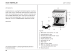
Swedish design
and manufacture
since 1967
Auto-Chl
MA60-17 rev.2
User manual
Copyright © 2011 Pahlén AB, Box 728, SE-194 27 Upplands Väsby, Sweden
Tel. +46 8 594 110 50, Fax +46 8 590 868 80, e-mail: [email protected], www.pahlen.com
Auto-Chl 12 & 25
ENGLISH
Product description
By adding salt to pool water and pumping the water through a chlorinator, you get a system that produces its own chlorine.
In normal circumstances, no chlorine needs to be added. Pure salt (NaCl) with a purity rating of at least 98% should be used.
The chlorinator is available in two sizes, intended for pools with water volumes of up to 75m³ and 150m³ respectively.
The chlorinator is a free-standing unit consisting of an electrolyte cell and a control unit. The control unit feeds current to the cell.
The electrolyte cell consists of a transparent tube containing metal plates or electrodes. It is between these electrodes that
chlorine production takes place.
The chlorinator continuously measures salt content. The production of chlorine can easily be adjusted using the arrow keys on
the front panel.
A clear display shows chlorine production in percent. Chlorination takes place in operational cycles that last 1 minute.
If production is at 50%, the current to the electrodes is on for 30 seconds and off for 30 seconds.
The chlorinator can also be controlled from an external Redox/chlorine supply unit.
The chlorinator is compatible with all chlorine products for water treatment available on the market. There is no problem using
the unit for supplementary chlorination or to switch between the chlorinator and different types of chlorine for pools.
The chlorinator can work together with UV light, an ozone generator, algaecides, cyanuric acid and many other supplementary
chemicals and methods.
When using the chlorinator, all the pool’s components should be made of titanium or plastic in order to avoid corrosion.
Technical specifications
Auto-Chl 12
Auto-Chl 25
Pahlén item no
418100
418125
Chlorine production (Cl2)
12 g/h
Operating voltage
25 g/h
240V/50Hz
Fuse
2A
Power consumption max
80W
Voltage/current out max
12VDC/6ADC
Size L x B x H
390 x 180 x 215 mm
Weight
1,7 kg
International Protection
Rating
IP44
Polarity reversal
every 4 hours
Pipe connection
Ø50
Minimum flow
90 l/h
Max temperature
45ºC
Max pressure
Material electrode
Control unit
Electrolyte cell
2 bar
Titanium with precious metal coating
Recommendations regarding water quality:
Chloride (salt) content 0.4-0.8%
pH 7.2-7.6
Alkalinity 60-120 ppm (mg/l)
Max sulphate content 50 ppm
Max magnesium (Mg2+) 30 ppm
Calcium hardness -300 ppm
In order to ensure reliable equipment with a long operational lifetime, it is important that the maintenance instructions are
followed, the pool water is properly balanced and that it follows the recommendations. For more information about balanced
pool water and proper care, please visit our website, read our Pool Guide brochure or ask at your pool store.
Safety
MA60-17E
The chlorinator should never be started or remain switched on without being entirely filled with water.
The chlorinator shall be firmly anchored and secured so that it cannot fall into the pool.
The warranty is only valid if the unit is correctly installed and maintained.
The chlorinator is not allowed to be used in whirlpool baths or whirlpool spas according to IEC 60335-2-60 A11.
“People with limited physical or mental capacity (including children) may not use the unit without instructions on how it is to be
used in a safe manner” as per IEC 60335-1.
9
Auto-Chl 12 & 25
ENGLISH
Installation, pipework
The chlorinator shall be installed horizontally.
It shall be installed lower than the lowest pool water level, on the return pipe after the filter and heater (if fitted), see the
drawing below, and preferably some way distant from the heat exchanger/electric heater so as to avoid being exposed to
excessive temperatures.
If the chlorinator is positioned such that there is a risk of freezing, installation shall be carried out in such a way that the
chlorinator can be drained of all water.
The display must be clearly visible and the keys must be easily accessible. Note the direction of flow, see the flow direction
arrow on the pipe casing.
The pipework shall be routed such that no air pocket/air lock can form.
Install a non-return valve between the chlorinator and the pool. If a shut-off valve is necessary, its rotary control shall be
removed so that accidental shut-off cannot take place.
Standard connectors are a coupling with 1 1/2” thread to Ø50 mm. The couplings shall only be hand-tightened.
Inlet
800
Skimmer
Light
Jet Swim
>400
Installation saltklorinator
Light
Non-return valve
Drain
>500
Heat exchanger
Aqua MEX
Filter
R
Boiler
Circulation
pump
Pump
Salt chlorinator
Non-return valve
Main drain
Installation, electrical system
Installation of the electrical system may only be undertaken by a certified electrician.
The electrical system shall only be installed after completion of pipework installation.
NB! The chlorinator should never be started without first being entirely filled with water.
Drawing no: M11267-0
100629 T.S
The chlorinator
The unit shall be firmly connected to earth and shall be protected by a residual-current device (RCD) with maximum leakage
current of 30mA.
The unit shall be fed via an external 2-pole switch.
The connecting cables shall be so long that it is possible to disconnect the chlorinator from the pipes and fill it with cleaning
agent for manual cleaning of the electrodes.
The chlorinator reverses polarity every 4 hours of operation, so it has to be allowed to run for at least 8 consecutive hours at a
time. If a timer or other timing device is used to control the pump, this shall be set at intervals longer than 8 hours.
Redox/chlorine control
MA60-17E
In order to ensure stable chlorine values for the pool water, an external Redox/chlorine control unit can be connected to the
chlorinator. This meter regulates the chlorinator by a control signal (+5V). The amount of chlorine to be produced varies
considerably between different installations depending on pool size, the number of bathers, turnover rate and so on. It is therefore necessary to test what size dose is suitable for each installation. The adjustment scope is the same irrespective of whether
there is an external control or not.
Connection of Redox/chlorine control unit: Connected through cable grommet to terminal PL4 and bridge connector at pos. SW2
one step to Redox on (see electrical wiring diagram).
10
Auto-Chl 12 & 25
ENGLISH
Display
Bottom side
Control and power card
Top side
Control and power card
Redox
1.Signal
2.±0V
3.+3,3V DC
4.Signal
5 Signal (oc+)
6.±0V (oc-)
Flow switch
Temp.sensor
Redox Off
Redox On
Memmory
card
Cell
Preparations
Add at least 4 kg of salt per m³ of pool water. The salt must have a purity rating of at least 98% and shall be poured directly into
the pool or into the equalizer tank.
Ensure that all the salt has dissolved before starting the chlorinator. It may take a day for the salt to dissolve. Salt dissolves
faster in warm water. If the salt content is not sufficiently high, the system will issue an alert and switch off.
Display
Normally the chlorinator’s chlorine production capacity in % is shown in a steady readout.
The yellow lamp lights up when power is supplied to the electrolysis.
The display returns automatically to the default display one minute after the most recent
button activation.
Chlorine production
Press the arrow key ▲ or ▼to increase or decrease chlorine production.
The production range is 4-100 %.
E.g.: When production is set at 50% the current to the electrodes is on for 30 seconds
and off for 30 seconds.
Indication of current salt content
Scroll ahead in the menu by pressing ▲ and ▼at the same time. SAL and current salt
content will flash alternately.
The value shown is the poolwater salt content in %.
The display automatically returns to showing chlorine production after one minute.
Calibration
First measure the salt content of the pool.
MA60-17E
Scroll ahead in the menu by pressing ▲ and ▼ at the same time untill SAL and a default value flash alternately, then press
▲ and ▼ at the same time untill CAL and a default value flash alternately. Calibrate the value by scrolling to the correct figure
(measured salt content in %) using ▲ and ▼. The calibrated value will then be displayed as a steady read-out.
The display automatically returns to showing chlorine production after one minute.
11
Auto-Chl 12 & 25
ENGLISH
Check before startup...
1. That the chlorinator is connected via the pump’s connections so that production only takes place when the pump starts up.
2. That the chlorinator is positioned such that water cannot drip or run onto the electrical components.
3. Leakages are immediately rectified.
4. That the heat exchanger/electrical heater is connected such that it can only be activated when the pool pump is operating.
A heat exchanger driven by water with a temperature of 80ºC can overheat and damage the cell housing if there is any
unintended natural circulation in the system.
5. Salt: Has the salt in the pool dissolved fully? (This may take up to one day.)
6. Measure salt content in the pool. It should be between 0.4-0.8%. If the salt content is below 0.4% the unit will issue an alert.
7. Calibrate the chlorinator, see above.
8. Water temperature: Measure the water temperature in the pool. Low temperature = less need of chlorine.
NB! The chlorinator should not be operated at all if water temperature is lower than 12ºC.
9.Measure also pH and alkalinity. These are vital parameters for good water quality.
10.Be prepared with a suitable test kit to be able to measure chlorine content. There are several variants and makes on the
market. (Take a sample in advance as a reference for function control.)
Start
1. Start the pump.
2. Start the chlorinator.
3. Set chlorine production to 100 % if the pool water is sufficiently warm. The pool water’s temperature should be higher than
17ºC for 100 % production. If the pool water’s temperature is lower than 17ºC: start at 10 % and raise as necessary.
Bear in mind that the chlorine content can rise quickly since the pool’s own consumption drops with lower water temperature.
Important! Never operate the chlorinator at full output if water temperature is low (see above) since this will reduce the life
expectancy of the cell.
4. Regularly check chlorine content, at the start of the season twice a day during the first few days. Even if the chlorinator is
operating at max output it may take time before it is possible to measure the pool’s chlorine content, particularly in fresh
water that has not been shock-treated with chlorine. However, the chlorine content may rise quickly after a few days and high
chlorine content increases the risk of corrosion.
If you want to immediately check whether the chlorinator is producing chlorine, take a water sample directly from one of the
pool’s injection nozzles.
Operation
Regulate your pool so that the rating for free chlorine is between 0.5-1 ppm for indoor pools and 0.7-1.5 ppm for outdoor pools.
The exact percentage at which chlorine production must be set to achieve this may vary significantly from one pool to another.
Here are a few authentic examples for Auto-Chl12 with a 4x8 m pool:
Types and variables Production
Indoor pool and 23ºC 40 %
Indoor pool and 35ºC 50-100 %
Outdoor pool 23ºC, covered 40 %
Outdoor pool 30ºC, not covered, a lot of sunshine 100 %
An indoor pool uses less chlorine than an outdoor pool. Here chlorine content can easily rise to high levels if it is not closely
monitored.
High chlorine content together with salt in the water makes for aggressive water that can damage metal, including stainless
steel, especially if the pH value is outside the recommended limits.
If there are any problems with stabilizing the required chlorine levels, an external Redox/chlorine control unit should
be connected.
MA60-17E
If the water temperature is below 17ºC the salt chlorinator should be run at max 50 %. The chlorine content will also rise quickly
since the pool’s own consumption rate drops when the water temperature is low. NB! The chlorinator should not be operated at
all if water temperature is lower than 12ºC.
Maintenance
During back-flushing/draining of the pool, production should be set at zero or switched off.
Weekly: Illuminate the cell and check that no coating has formed on the electrodes.
Put your hand on the salt chlorinator and check that it does not feel hot.
Check the salt content of the pool water (read off the display).
Note any alerts and warnings. Enter them in the pool’s log book.
Spring and summer: Check the salt content – calibrate the salt chlorinator’s measured values.
In a normal private swimming pool, the water’s salt content should be measured and checked at least
twice a year using a separate salt gauge or test strip.
Salt
Check the salt content at the same time as routine inspections are carried out on chlorine, pH and other water parameters.
For this purpose there are both simple test strips that show salt content in ppm (1000 ppm= 0.1 %) and digital measuring
equipment. Salt is consumed only in the event of back-flushing, leakage or water change. Note that when there has been a
long period of heavy rain, the salt content of outdoor pools will drop. In seawater pools, no salt needs to be added.
A higher salt content gives longer electrode life expectancy, but also increases the risk of
corrosion of the pool’s metal parts, especially if the chlorine content is high.
12
Auto-Chl 12 & 25
ENGLISH
Decalcification
Lime which is a natural component of water is deposited on the electrodes in the cell. This shortens the electrodes’ lifespan.
The electrodes are self-cleaning since their polarity is reversed every 4 hours of operation. For this to work satisfactorily, it is
necessary for the pool water’s pH rating, alkalinity and so on to be within the recommended limits and the unit to operate for
at least 8 consecutive hours.
If lime nonetheless builds up, the cell has to be decalcified. Water with high alkalinity (above 120 ppm) and high pH (above 7.6)
runs an increased risk of cell scaling. This appears as a white coating between the electrodes.
Inspection between the cell’s plates. There should be a clear space between them. If the cell is clogged, it can quickly be
totally destroyed!
• If there is a brown coating (iron or manganese) the cell has to be dismantled and cleaned using a special agent.
Contact Pahlén for support.
• If there is a white/light coating (lime) the cell must be dismantled and cleaned using a decalcification agent, see below.
Manual decalcification:
1. Switch off the current supply to the salt chlorinator.
2. Stop the pump and shut off the valves before and after the salt chlorinator.
3. Undo the pipe couplings.
4. Plug one end of the chlorinator.
5. Read and follow the safety instructions for the cleaning agent.
6. Fill the cell housing with cleaning agent. Let it act until all the coating has disappeared. DO NOT poke anything between
the plates or in the cell.
(The cleaning agent is acidic and can be used for pH adjustment in your pool or can be saved for use the next time.)
7. Rinse with water.
8. Refit the cell.
9. Screw the pipe couplings back into place (only finger-tight).
10.Start up and check there are no leaks anywhere.
11.Check that the salt chlorinator can operate at its full production capacity.
Winter/risk of freezing
If there is a risk of freezing, the system must be drained of water and the power supply switched off. The salt chlorinator must be
undone and entirely drained of all water.
Alarms, warnings and fault codes
An alarm is only issued if the limit has been exceeded. When the values return to normal the alarm is reset and so too is the
warning.
Type
What happens - cause
Action
Alarm: A1
Stops production.
A1 appears in the display, steady readout.
Alarm appears when the chlorinator has high voltage (12V).
This occurs when there is too little salt in the pool water or when
the electrodes are used up.
Check the salt content of the pool
water.
Replace the cell package.
Stops production.
Check the pump, non-return valve
or shut-off valves, check other stoppages in the circulation system.
When flow returns to normal, the
alarm is reset and production continues.
Alarm: FLO
FLO appears in the display with a steady readout when there is
no flow or insufficient flow through the cell housing.
Alarm: HT
Stops production.
HT appears in the display, steady readout.
This alarm appears when temperature in the cell exceeds 45ºC.
Warning: FAULT A
When current supply is more than
Production continues.
FEL and A flash alternately.
4A, the warning is reset.
This warning appears when current to the electrodes is less than
4A.
Warning: Add SAL
Add salt to the pool water, wait until
it is dissolved.
This warning appears when the pool water’s salt content is lower To raise it by 0.1 %, add 1 kg/m³
than 0.40 %.
pool water.
Production continues.
ADD and SAL flash alternately.
MA60-17E
Subject to any printing errors. The right to change technical specifications and product range without notice. Deviation in color
may arise from the printing process.
13