1
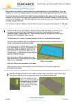
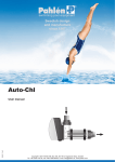
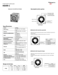
Swedish design
and manufacture
since 1967
MiniMaster
MA60-16 rev.5
Manual
User manual
Инструкция
Copyright © 2011 Pahlén AB, Box 728, SE-194 27 Upplands Väsby, Sweden
Tel. +46 8 594 110 50, Fax +46 8 590 868 80, e-mail: [email protected], www.pahlen.com
ENGLISH
MiniMaster
1. Product description
MiniMaster is an electronic unit for checking and controlling the pH and/or chlorine level in a pool.
The pH value is measured with a pH electrode and the chlorine level is measured with a free chlorine electrode.
MiniMaster can be linked with dosing equipment for acid/alkali (pH) and chlorine.
The package contains: 1 control unit, 2 4m PE hoses, prefilter and hose connections.
Electrode kit supplied separately: contains electrode(s), cleanser and for the pH model also buffer solution pH 7.3.
2. Technical data
MiniMaster pH/chlorine
MiniMaster chlorine
MiniMaster pH
Power consumption - excl. dosing equipment
4W
2W
2W
Power consumption - dosing equipment (max.)
2x100W
100W
100W
Rated current
1A
Voltage
220-240V 1~N 50/60Hz
Temperature range
0 to +45°C
Enclosure rating
IP44
Measurements L x W x H
310 x 85 x 500 mm
Weight
2 kg
3. General info
MiniMaster measures and continuously indicates the pool water’s pH reading and chlorine content.
Upon deviant readings, the control unit gives signals to external dosage equipment that applies doses.
To maintain balanced water quality, it is important to follow our recommended readings as per below.
pH readings outside the recommended readings will provide misleading chlorine readings at MiniMaster.
If the pool water was previously dosed with organic chlorine containing cyanuric acid (such as in tablet/puck form), this may
cause an incorrect chlorine measurement (for action; see section 8 point 8).
We recommend use of a photometric test instrument for reference measurement and calibration.
MiniMaster must be mounted on a wall or similar and must sit straight. The installation space for MiniMaster is recommended
to be indoor or under a roof, and to be easily accessible to be able to easily take readings, perform service, take water samples
and clean the prefilter.
Recommended readings regarding water quality
Chlorine content:
0.5-1.5 mg/l (ppm)
pH reading: 7.2–7.6
Alkalinity: 60-120 mg/l (ppm)
Chloride (salt) content: max 5000 mg/l (ppm) = 0.5%
Calcium hardness: 100-300 mg/l (ppm)
Cyanuric acid:
max 5 mg/l (ppm)
For more details on pool chemistry and care, refer to the pool user’s guide on our website http://www.pahlen.com/users-guide/
4. Safety
Dosage of chlorine, acid or the like shall be done AFTER all other equipment to minimise the corrosion risk.
Dose points in the circulation system for liquid acid and chlorine shall be as far apart as possible, although a minimum of
500 mm and chlorine dosing shall always be placed last, see picture 3
5. Dimensions
85
MiniMaster chlorine or pH
310
310
310
This document and its contents are the exclusive
property of Pahléns and may not be copied,
reproduced, transmitted or communicated to a third
party, or used for any purpose without written permission.
MA60-16E
500
500
500
500
83
MiniMaster ph/chlorine
310
E
Sid 2.
11
Till MA60-16
Designed by:
Surface treatment
The tolerance class in accordance with this
part of ISO 2768-1
Box 728, SE-194 27 Upplands Väsby, Sweden
Phone +46 8 59411050, Fax +46 8 59086880
Assembly drawing no.
MiniMaster pH - fritt klor
MiniMaster pH - Redox
Drawn by: Date
CRO 2010-09-01
Approved by:
Art.no.
Scale
416620-02
Revised by: Date
ASA 2014-02-26
Drawing number
Rev.no.
M11278 5
ENGLISH
MiniMaster
6. Installation
Tapping sleeves are recommended for installation of the pipe lines for the connection points of the measurement water to and
from MiniMaster, and for the dosage points for liquid acid and chlorine via hose pumps.
Hard PE hose is included that shall sit between MiniMaster, the prefilter and the pipe lines.
Picture 1
1. Install MiniMaster against a wall.
Install the included connections on MiniMaster,
see picture 2. Disconnect the brace (M), fold the
modules forward, screw the connections on
MiniMaster's inlet and outlet.
2. Assemble the prefilter, see instructions MA60-23.
NOTE: The top on the filter has an arrow
marking the flow direction.
3. Install the prefilter at a suitable location near
the MiniMaster.
4. Cut the included hose to suitable lengths and
connect them without sharp bends between the
MiniMaster and prefilter.
NOTE: When installing hose in hose couplings of an insert type:
Make a straight cut with a sharp knife in the hose, push in the
hose end approx. 10mm in the coupling, then pull the hose
backwards for secure locking.
5. Inlet A: Install a tapping sleeve after the sand filter on the
pressure side of the pool circulation pump (see A picture 3).
6. Outlet B: Install a tapping sleeve after the skimmer on the
suction side of the pool circulation pump (see B picture 3).
7. Cut the included hose to two suitable lengths, install hose
coupling to the respective tapping sleeve.
Use threaded seal at the connection of bushing 1/4"-1/2" to the
tapping sleeve/line pipe.
8. Connect the one hose to the prefilter and to inlet A.
9. Connect the other hose to the prefilter and to outlet B.
Alternative placement of outlet B: Guide the hose directly down
in the skimmer (C, picture 3) or to an equalization tank.
N
10.If dosage pumps are used for liquid chlorine and acid/alkali,
M
the dosing points shall be placed a MINIMUM of 500 mm
apart from each other, after other equipment for heating/other
disinfection.
Chlorine dosing is always placed last.
Picture 2.
This document and its contents are the exclusive
property of Pahléns and may not be copied,
reproduced, transmitted or communicated to a third
party, or used for any purpose without written permission.
M
MA60-16E
1.Skimmer
2. Main drain
3.Inlet
4. JetSwim
5.Light
6. Circulation pump pool
7.Filter
8. Heat exchanger
9. Check valve
10.Drain
11. Circulation pump heat
12. Boiler
13.MiniMaster
14. Prefilter MiniMaster
15. Chlorine dosing
16. Chlorine
17. Acid/alkali dosing
18. Acid/alkali
Ball valve L2
1/4”
This document and its contents are the exclusive
property of Pahléns and may not be copied,
reproduced, transmitted or communicated to a third
party, or used for any purpose without written permission.
Fig. 4.
C
Sid 5 MA60-16
1/4”
Ball valve L1
N = Measurement water tap
M = Measurement water outlet
13
3
1
4
5
15
5
16
2
17
9
18
B
14
A
8
7
11
9
6
10
10
12
Picture 3
12
ENGLISH
MiniMaster
7. Installation, electrics
Electrical installation must always be carried out by a an authorized electrician.
Pipe installation must be complete before electrical installation is started.
Pahlén recommends a fixed installation with a 2-pole working breaker.
Loosen the cover's four screws. The control unit cover can easily be hooked into open position to facilitate the installation work.
NOTE: Ensure that the band cable from the circuit board to the cover is not pinched.
Hook on the cover according to picture 5. Connect the power cable and any dosing equipment as indicated in the diagram below.
The multi-pole contacts to the circuit board can be uninstalled for access to screw plinths for the respective cable connection.
Circuit board - control unit Chlorine and/or pH
AC IN
Main current connection to the unit.
Display panel
Dosage
equipment
1~230V AC
Relay connection
Connection of dosing equipment, 230 VAC,
NOT potential free. Max 1A
R+:Phase (for dosing chlorine and
pH-elevating agent).
R-: Phase (for dosing pH-reducing agent).
RN: Zero/Neutral (common for dosing).
OC+/OC-:
Red
Black
GND
Red
Black
Transistor “open collector” output for
dosing equipment, max 5V.
Brown
Green
White
Connection of flow
signal between
circuit boards
(416620-X only).
Dosage
equipment
max 5V DC
Signal (OC+)
±0V (OC–)
pH/Chlorine:
Connector for electrode connection.
GND:
Ground socket connection
(Chlorine measurement only).
Picture 5
L1
N
RN
R +
R –
Carefully hook the cover on
the circuit board's edge.
pH
PB100
MA60-16E
BNC
13
ENGLISH
MiniMaster
8. Start
Preparation
1. C
heck that the pool's water readings are within recommended limits, use photometric measurement equipment.
2. Just before start, the electrodes are installed in the respective module. Then connect the electrode's BNC contact to the
respective control unit, see picture 5. NOTE: The electrodes shall always be stored
in liquid.
83
310
Picture 6
Picture 7
G
E
E
1
2
3
4
5
6
7
F
This document and its contents are the exclusive
property of Pahléns and may not be copied,
reproduced, transmitted or communicated to a third
party, or used for any purpose without written permission.
First read through the paragraph on "LEDs" in section 10 Operation, which describes
H
MiniMaster's LED signals and what they mean.
The pool circulation pump must be running in order for the unit to function.
1. Switch on MiniMaster.
J
2. Open all taps.
3. Press the Flow button (F).
(Only required on the left-hand unit when there are two).
4. Adjust the flow with the flow screw (H) until LEDs no. 1 to 4 are on.
Check that the unit has a flow, can be seen in the window (J), and that there is a free flow
through the hoses. If the outlet hose is installed on the pump's suction side (alt. B picture 3), ball valve L2 (picture 2) shall be open 25-50% to avoid a vacuum in the flow cell.
5. Let the flow cell flow for at least 30 minutes for stabilization of electrodes and elimination
of air in the flow cell.
6. Check the pool's pH reading.
7. Balance the pH, see below.
500
Start-up
E
Sid 2.
Till MA60-16
Balance pH
Take measurement water from the drain tap (N, picture 2) and check the pool's pH by using photometric measurement
equipment.
Balance the pH to 7.2-7.4 by manually dosing with acid (upon high pH) or alkali (upon low pH) directly in the pool or with
dosing equipment (accessory) for MiniMaster;
- press button (E) to activate the dosing function (LED is lit with a steady glow).
- press button (G) for 3 seconds for forced dosing for 30 seconds.
- then press button (E) to stop the dosing function (LED blinks).
Concentrated dosing can initially cause major fluctuations depending on pool size and turnover rate. Let the fluctuations
level off and carefully check that the pH has stabilised after around 5 hours.
8. T
he water's pH must be balanced before going on to adjust the free chlorine reading, see below. Incorrect pH causes
in-correct free chlorine readings.
Adjust free chlorine
Take measurement water from the drain tap on the prefilter (N, picture 2) and check the pool's free chlorine by using photometric measurement equipment.
Adjust the chlorine reading to 0.5-1.5mg/l by either dosing chlorine directly in the pool or with dosing equipment for MiniMaster;
- press button (E) to activate the dosing function (LED is lit with a steady glow).
- press button (G) for 3 seconds for forced dosing for 2 minutes
- then press (E) to stop the dosing function (LED blinks).
Concentrated dosing can initially cause major fluctuations depending on pool size and turnover rate. Let the fluctuations
level off and carefully check that the chlorine content has stabilised after around 5 hours.
NOTE: If organic chlorine (weekly chlorine in puck form) is used or has been used in the pool, this causes cyanuric acid in
the pool water.
Cyanuric acid in the water causes misleading free chlorine readings and calibration errors in MiniMaster. If so, dilute the pool
water with so much new water that the cyanuric acid reaches the recommended value (see "Recommended values.." in
section 3 General info).
MA60-16E
9. W
hen the values for both pH and free chlorine are in balance at the same time, one can continue and calibrate MiniMaster.
Each unit is calibrated separately. They are independent of each other.
14
Box 728
Phone +
ENGLISH
MiniMaster
9. Calibration
The electrodes shall be cleaned, the flow cell shall have the right flow and the dosing mode shall be deactivated before calibration is done. Every unit is calibrated separately, they are independent of each other.
Calibrate pH
1. R
eference to calibrate against can either be the pool water (alt. 1) or buffer fluid (alt. 2). The pH value shall be between 7.2 and 7.4.
Alt. 1 pool water: Take measurement water from the drain tap on the prefilter (N) and check it with the photometric measurement instrument.
Alt. 2 buffer fluid: Switch off the measurement water to the flow cell. Disconnect brace (M) fold out the modules, disconnect
the electrode's BNC contact (see picture5) from the control unit, unscrew the pH electrode from the module, put back the BNC
contact. Pour reference liquid pH 7.3 in a measurement glass, so much so it covers at least 2cm of the pH electrode (tapped
reference liquid may not be reused) and let the electrode stand in the liquid for at least 30 seconds.
2. Calibrate the unit by pressing the two calibration buttons (F+G) at the same time and keep them pressed.
3. The LED flashes quickly (approx. 5 times per second) to confirm that calibration is in progress.
The flashing slows down once calibration is complete. You can then release the buttons.
4. The calibrated value is saved in the unit memory. The green LED in the middle turns on and now represents this value.
Once the unit is calibrated, dosing is activated by pressing the On/Off button (E) on the control unit.
The LED for the current value is now lit with a steady glow.
Calibrate free chlorine
1. If pH has been calibrated with buffer fluid, but the pool water has an entirely different pH, wait until MiniMaster has achieved
pH 7.2-7.4 either through automatic or manual dosing of acid/alkali.
2. Test measure free chlorine: Take measurement water from the drain tap (N) on the prefilter. Use photometric measurement
equipment and check that the free chlorine lies within 0.5-1.5mg/l (ppm).
3. Calibrate the unit by pressing the two calibration buttons (F+G) at the same time and keep them pressed. The LED flashes
quickly (approx. 5 times per second) to confirm that calibration is in progress.
4. The flashing slows down once calibration is complete. You can then release the buttons.
The calibrated value is saved in the unit memory. The green LED in the middle turns on and now represents this value.
5. Once the unit is calibrated, dosing is activated by pressing the On/Off button (E) on the control unit.
The LED for the current value is now lit with a steady glow.
If calibration fails, it is often due to an implausible value (the previous value is then retained). The calibration then needs to be
redone or see section 14 Trouble-shooting.
10. Operation
The measured value in the pool is indicated on the display with the seven LEDs.
A green LED shows MiniMaster's calibrated value (everything is OK) and is the unit's desired value. Yellow/red LED indicates a
deviation from the calibrated value, see table below.
A blinking LED means that MiniMaster is measuring and a steady glow means measurement and an activated dosing mode,
for more information see "LEDs" on the next page.
Upon a high pH:
Upon a low pH:
Upon a low free chlorine:
Relay output R- activated refers to acid dosing.
Relay output R+ activated refers to alkali dosing (see section 12 - Change of factory settings).
Relay output R+ activated refers to chlorine dosing.
Picture 8
E
↓
LED →
pH
Free chlorine
MA60-16E
Flow L/h
G
E
1
2
3
4
5
6
7
F
1. Red
Low
2. Yellow
3. Yellow
4. Green
Ok
5. Yellow
6. Yellow
7. Red
High
< 6.8
6.8-7.0
7.0-7.2
Calibration value
(rec. 7.2-7.4)
7.4–7.6
7.6-7.8
>7.8
< -80%
-60%
-30%
Calibration value
(rec. 0.5-1.5 ppm)
+30%
+60%
>+80%
<10
11-18
18-26
27-52
53-72
72-100
>100
15
ENGLISH
MiniMaster
LEDs
Type of LED signal
Meaning
The two red LEDs are lit with a steady glow:
The unit is not calibrated. Dosing is not possible.
The two red LEDs blink:
Flow too high or too low. Dosing is deactivated.
LED is lit with a steady glow:
Measurement ongoing, dosing mode is activated.
Blinking LED:
Measurement ongoing, dosing mode is not activated.
Rolling LEDs:
Forced dosing is in progress.
11. Buttons
E
On/Off - activates/deactivates the dosing function
F
Flow - pressed button shows the current flow through the MiniMaster flow cell.
F+G Calibration
G
Forced dosing - pressed button for 3 seconds causes forced dosing for 2 minutes of chlorine or 30 seconds for pH
(rolling LEDs). If an ongoing forced dosing needs to be discontinued early: press button (E).
12. Change of factory settings
Time-Out – exceeded dosing time
The time-out function is a built in safety catch in the software and is a limit on continuous dosing time.
The function is factory set and shuts off the dosing and triggers an alarm after 90 minutes of continuous dosing. This is to prevent
unreasonable dosing, which can occur in the event of e.g. leakage or measurement error.
If the dosing equipment needs more than 90 minutes of dosing to achieve the correct values, the Time-Out function can be
deactivated, see below.
When the power to MiniMaster is turned on, a start sequence is triggered after about 2 seconds and the LEDs (1-7) are lit in
sequence, thereafter the set mode is shown (see point 5 below).
Deactivation of Time-Out (only the chlorine unit)
1.
2.
3.
4.
5.
Switch off power to MiniMaster.
Switch on the power.
Press button E when LED 1 turns on, release when LED 2 turns on (respective LED blinks 2 times/second).
Press button E when LED 6 turns on, release when LED 7 turns on.
When the start sequence is done, the set mode is confirmed with a blinking indication:
‒ LED no. 3, 4 and 6 blink = deactivated Time-Out (‒ LED no. 3, 4 and 5 blink = activated Time-Out).
Save the setting by holding in button E for 3 seconds directly after finished confirmed LED indication (blinks 5 times) until
LED 1 or 7 blinks rapidly.
6. To check which setting the unit has: turn off, wait approx. 3 sec., turn on power to the unit ‒ LED 1 to 7 blinks during the start
sequence with ensuing blinking indication as per point 5.
7. To activate the Time-Out function again, repeat from step 1.
NOTE: If Time-Out is deactivated an extended period of time and a fault arises, an unlimited amount of chemicals can be dosed
into the pool or leak out in the machine room. Always check hoses, connections and chemical levels regularly and ensure that
Time-Out is activated.
Dosing setting (acid or alkali)
Dosing function of pH-reducing agent (acid) is factory-set on the pH unit.
When the power to MiniMaster is turned on, a start sequence is triggered after about 2 seconds and the LEDs 1 to 7 are lit in
sequence, thereafter the set mode is shown, see point 5 below.
If you instead want to dose alkali for a pH-increasing effect, a resetting must be done as per below:
NOTE: This only applies to the pH unit and pH calibration must be done before this change is begun.
Resetting to dosing of Alkali (only the pH unit)
MA60-16E
1.
2.
3.
4.
witch off power to MiniMaster.
S
Switch on the power.
Press button E when LED 1 turns on, release when LED 2 turns on (respective LED blinks 2 times/second).
Press button E when LED 6 turns on, release when LED 7 turns on.
16
ENGLISH
MiniMaster
5. W
hen the start sequence is done, the set mode is confirmed with a blinking indication:
‒ LED no. 2, 4 and 5 blink = alkali dosing activated).
Save the setting by holding in button E for 2 seconds directly after finished confirmed LED indication until LED 1 and 7 blink
rapidly.
6. To check which setting the unit has: turn off, wait approx. 3 sec., turn on power to the unit ‒ LED 1 to 7 blinks during the start
sequence with ensuing blinking indication as per point 5.
7. To change the dosing setting for acid, repeat from step 1. When the start sequence is done, the set mode is confirmed with
a blinking indication:
‒ LED no. 2, 4 and 6 blink = acid dosing activated.
13. Care
• Upon back flushing of the pool's sand filter - first close the shut-off valves (L1 and L2) on the prefilter to and from MiniMaster.
• Check flow with pressed button (F) - adjust to the right flow with adjustment screw (H) on the start module.
• Reference measurement of chlorine and pH should be performed 1-2 times per month with digital photometric measurement
equipment and with subsequent calibration. Take measurement water from measurement water outlet on the prefilter.
Upon a deviation from calibrated value - clean the electrodes and calibrate afterwards.
• The plug threads and O-rings should be lubricated at least once per year with silicone grease with PTFE (non-petroleumbased grease).
• Check hoses, connections and chemical levels regularly.
Electrodes
Should be cleaned regularly (see instruction MA60-06: Electrodes, handling and care), at least once a month for a fresh water
pool. For a salt water pool, contact ÅF for information on handling and care of MiniMaster in salt water.
1. Switch off dosing (on/off button E) - LED blinks.
2. Cut off the flow of water by closing the ball valves (L1 and L2).
3. Lift up the lock arm (M) and lower the modules forward, see picture 3.
4. Disconnect the electrode's BNC connector (see picture 5) from the control unit.
5. Unscrew the electrode and lift it upwards.
6. Clean and rinse off the electrode. Reinstall the electrode and BNC connector. Open the ball valves (L1 and L2).
7. Activate dosing (on/off button E) - LED is lit with a steady glow.
Filter
Check the filter regularly and clean as necessary. Replace the cartridge when necessary.
1. Switch off dosing (on/off button E) - LED blinks.
2. Cut off the flow of water by closing the ball valves (L1 and L2).
3. Unscrew the filter can where the cartridge sits.
4. Replace the filter or rinse it clean with regular water. A soft brush can be used if necessary.
5. Reinstall filter. Open the ball valves (L1 and L2).
6. Activate dosing (on/off button E) - LED is lit with a steady glow.
Adjustment screws
Adjustment screws (H) and Measurement water tap (N) are cleaned as necessary so they do not seize due to being coated.
1. Switch off dosing (on/off button E) - LED blinks.
2. Cut off the flow with the ball valves (L1 and L2).
3. Screw out the adjustment screw, rinse it and wipe it off.
4. Lubricate the O-ring and plug thread with a little silicone grease. Reinstall them. Open the ball valves (L1 and L2).
5. Activate dosing (on/off button E) - LED is lit with a steady glow.
Winter storage
Upon the risk of freezing, the modules and prefilter should be emptied from water, bottom plugs removed, electrodes uninstalled
and stored frost-free in their delivery container filled with tap water.
Handling of chemicals
MA60-16E
!
Liquid chlorine and liquid acid are strong chemicals with alkali and acidic properties.
These MAY NOT be mixed with each other as this can cause strong chemical reactions.
The different chemical containers shall be placed well separated from each other and stand in its own
reclamation container.
When handling these chemicals, protective equipment shall always be used, such as protective gloves,
apron and protective glasses.
17
ENGLISH
MiniMaster
14. Operating information and troubleshooting
LED signals
Type of LED signal
Explanation
The two red LEDs are lit with a steady
glow
The unit is not calibrated - dosing is not possible
The two red LEDs flash alternately
Flow too high or too low - dosing is deactivated
All red and yellow LED's blink
simultaneously
Time-Out function:
Continuous dosing has been under way more than 90 min - dosing is turned off.
• Check dosing pump's function and setting.
• Check that the chemical level is not too low in the drums.
• Check leaks/function of dosing hoses, dosing points and dosing pumps.
Restart:
First turn off the dosing (On/Off button E), wait a few seconds,
then start the dosing by pressing the On/Off button again (E).
LED is lit with a steady glow
Dosing is activated; measurement is in progress
Blinking LED
Dosing is NOT activated, but measurement is in progress
Rolling LEDs
Forced dosing is in progress.
Only applies to the chlorine unit:
Blinking LED 3, 4, 5 after start sequence
Time-Out activated = dosing is blocked after 90 minutes of continuous dosing,
(factory setting)
Blinking LED 3, 4, 6 after start sequence
Time-Out deactivated (unlimited continuous dosing)
Only applies to the pH unit:
Blinking LED 2, 4, 5 after start sequence
Alkali dosing activated
Blinking LED 2, 4, 6 after start sequence
Acid dosing activated
Troubleshooting
Fault type
Action
The unit/dosing equipment does not start
• If the unit is interlocked over a turned off circulation pump, the unit will not start.
• Check fuses on the circuit board.
Unstable/low flow in the flow cell
Check/clean prefilter. Clean and lubricate the adjustment screw on the flow cell.
Unit cannot be calibrated
• Low/high measurement water flow (only chlorine unit) - check filter.
• Unreasonable measurement values; free chlorine < 0.3ppm or > 3.0ppm
- check the chlorine values with photometric equipment.
• High Cyanuric acid contents in the pool water
- check with photometric equipment.
Dilute the pool water with tap water as necessary.
• Electrode or connection error
- check connections, clean electrodes or replace them.
High and low values during operation
- not stable calibrated value.
• Dosing set too high or low. Adjust dosing based on pool volume and turnover
rate.
• Check that the water flow is even through the flow cell.
• Check electrodes' condition and connections.
Underpressure in return hose/flow cell
Press the Flow button (F, see picture 6), open Adjustment Screws (H, see
picture 7) to max position. Then cut the flow with the ball valve L2 (see picture 2)
carefully until LED 1 to 4 are lit.
Reservation
MA60-16E
We reserve the right to correct any printing errors. We also reserve the right to make changes to technical specifications for
MiniMaster or its manual without prior notice.
Colour deviations may occur due to technical reasons related to printing.
18