1
CD Automation srl
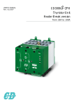
CD3000S-1PH Analog Input from 15A to 110A
User’s manual
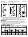
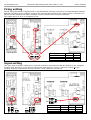
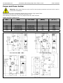
Diagram of control connection
15÷25A
35÷45A
60÷110A
L1
L1
L1
L1
L1
L2/N
L2/N
L2/N
L2/N
L2/N
1
1
L2/N
1
LOAD
Fan Power Supply
(Only for size 110A)
H.B.
4
Alarm
L1
L1
1 2 3 4 5
Ext. CAL
12-24Vdc
H.B.
4
Alarm
C1 C2 C3
6 7 8
1 2 3 4 5 6 7 8
T1
- ++ -
-+
-+
3
3
C.T.
Input :
SSR
0-10Vdc
4-20mA
C.T.
LOAD
H.B.
4
Alarm
Ext. CAL
12-24Vdc
3
2
2
Aux :
12-24v
AC/DC
FAN
Ext. CAL
12-24Vdc
T1
Input :
SSR
0-10Vdc
4-20mA
L1
Aux :
12-24v
AC/DC
LOAD
Input :
SSR
0-10Vdc
4-20mA
2
Aux :
12-24v
AC/DC
Note:
•
The user installation must be protecting by electromagnetic circuit breaker or by fuse isolator (¹).
•
With AC power supply it's not possible connect the zero terminal of Analogue Input to the earth (²).
•
A series connection between analogue inputs of the units is not possible (³).
•
See par. “HB alarm contact” (⁴).
•
The Current Transformer (C.T.) must be mounted only with the HB option and without ICT option.
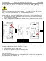
Wiring instructions
The unit has isolated heatsink. For safety connect the heatsink to earth using its terminal with earth
symbol. The CD3000S can be susceptible to airborne interferences from near equipment or from
interferences on main supply, so a number of precautions must be taken.
•
•
•
•
Contactors coils and chokes must have in parallel a RC filter and must be supplied with a different voltage line.
All input/output signals must use screened bifilar wires.
Signal input and output must not route in same cable try and must not be parallel.
Local regulations regarding electrical installation should be rigidly observed.
Use copper cables and wires rated for use at 75 °C only.
Power cable torque (suggested)
Current
Connector
Type
Torque
Lb-in (N-m)
Wire Range
AWG/kcmil
Wire Terminal
UL Listed (ZMVV)
15A,25A,35A,45A
M5 Screw
26.6 (3.0)
8
Wire Pin
60A,90A, 110A
M6 Screw
70.8 (8.0)
1
Fork/Spade Terminal
Copper Tube Crimp. Lug
Load
Cable
Screw M
mm² AWG
4
12
M5
6
10
M5
10
8
M5
10
8
M5
16
6
M6
35
3
M6
35
3
M6
Earth
Cable
Screw M
mm² AWG
4
12
M5
4
12
M5
6
10
M5
6
10
M5
6
10
M5
6
10
M5
6
10
M5
Cable dimensions (suggested)
Current
15A
25A
35A
45A
60A
90A
110A
Supply
Cable
Screw M
mm² AWG
4
12
M5
6
10
M5
10
8
M5
10
8
M5
16
6
M6
35
3
M6
35
3
M6
Auxiliary Supply
Cable
mm² AWG
0,50
18
0,50
18
0,50
18
0,50
18
0,50
18
0,50
18
0,50
18