1
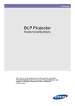
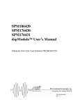
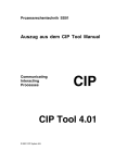
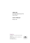
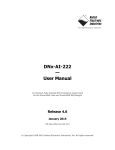
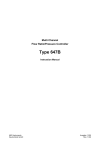
AC SERVO DRIVE DSD SERIES
USER’S MANUAL
VITAL SYSTEMS INC
http://www.vsys.co
Precautions and Explanations
■Transport and storage
● Do not stack product package more than six layers;
● Do not climb, stand on or place heavy stuff on the product package;
● Do not pull the cable still connecting with machine to move product.
● Forbid impact and scratch on the panel and display;
● Prevent the product package from humidity, sun exposure, and rain.
■Wiring
● Ensure the persons involved into wiring and inspecting are specialized staff;
●Guarantee the product is grounded with less than 4Ω grounding resistance. Do not
use neutral line (N) to substitute earth wire.
● Ensure grounding to be correct and solid, in order to avoid product failures or
unexpected consequences;
● Connect the surge absorption diodes to the product in the required direction,
otherwise, the product will be damaged;
● Ensure the power switch is OFF before inserting or removing plug, or disassembling
chassis.
■Overhauling
● Ensure the power is OFF before overhauling or components replacement;
● Make sure to check failures after short circuit or overloading, and then restart
the machine after troubleshooting.
● Do not allow to frequently connect and disconnect the power, and at least one
minute interval between power-on and power-off.
■Maintenance
Please implement routine inspection and regular check upon the following items,
under the general usage conditions (i.e. environmental condition: daily average 30
℃, load rate: 80%, and operating rate: 12 hours/ day)
Routine Inspection (Regular Check):
Confirm environmental temperature, humidity,dust, or foreign objects.
Confirm abnormal vibration and noise;
Check whether vents are blocked by yarn etc..
Routine(One year):
Check whether solid components are loose .
Confirm whether terminal block is damaged.
■ Guarantee period
● the guarantee period is 12 months(from the date of shipment).if it is broken under
correct operation in guarantee period.we can promise give our customer repair for
free.
● broken by the reason as below, customer need pay for the maintainance:
1.wrong operation and repair by customer themselves,retrofit induce driver
broken.
2.broken by fire,water,abnormal voltage,other accident or twice accident
induced device broken.
3.broken by human accident.
4.doesn’t operate base on our use mamual book.
Anyother reasons,please contact us.
Contents
CHAPTER1 PRODUCT’S INSPECTION AND INFORMATION..........................................1
1.1 Product’s inspection............................................................................................................ 1
1.2 Product’s nameplate............................................................................................................ 1
1.3 Technical specifications of servo driver...............................................................................3
CHAPTERⅡ INSTALLMENT...............................................................................................5
2.1 SERVO DRIVER’S INSTALLMENT................................................................................5
2.1.1 Installing environmental conditions.......................................................................5
2.1.2 Use under harsh environments ..............................................................................5
2.1.3 Installation method ................................................................................................5
2.1.4 Multi- drivers install ..............................................................................................6
2.2 Servo motor’s install ...........................................................................................................6
2.3 Notice of installment...........................................................................................................6
2.4 Motor rotation direction definition.....................................................................................6
CHAPTER III WIRING ..........................................................................................................8
3.1 Wiring requirement.............................................................................................................8
3.1.1 Driver terminal.......................................................................................................8
3.1.2 Wire specification..................................................................................................9
3.2 Motor and power’s wiring diagram....................................................................................9
3.2.1 wiring diagram......................................................................................................9
3.3 Power line terminal even chart .........................................................................................10
3.4 CN1 Signal controller terminals .......................................................................................10
3.4.1 Terminal arrangement...........................................................................................10
3.2.2 Terminal name and function ............................................................................... 11
3.5 CN2 encoder Terminal......................................................................................................12
3.5.1 Terminal arrangement...........................................................................................12
3.5.2 Terminal definition...............................................................................................12
3.6 CN3 Computer communication terminals ........................................................................13
3.7 whole wiring diagrams......................................................................................................13
3.8 Principles of input and output interfaces ..........................................................................16
3.8.1 EN, MODE, INTH, CW, and CCW Switch Input Interface................................ 16
3.8.2 SRDY, ALM, BRAKE, COIN, and OZ Switch Output Interface .......................16
3.8.3 Pulse Signal Input Interface: ...............................................................................17
CHAPTER IV DISPLAY AND PARAMETER SETTINGS .................................................19
4.1 Servo System panel...........................................................................................................19
4.2 Keyboard Operation..........................................................................................................19
4.3 Parameter Settings ............................................................................................................20
4.3.1 Password input and changes...................................................................................21
4.3.2 Parameter settings...................................................................................................21
4.3.3 Parameter writing....................................................................................................22
4.3.4 Parameter initialization...........................................................................................22
CHAPTER V PARAMETERS .................................................................................................23
Chapter VI Operation
JOG Control of Servo System...................................................................................................33
Position Control of Servo System ............................................................................................33
Speed Control of Servo System.................................................................................................34
Torque Control of Servo System................................................................................................34
Internal Speed Control Servo System........................................................................................ 35
Internal Four Section Position control servo system .................................................................35
CHAPTER VII ERROR ALARM .............................................................................................36
CHAPTER VIII DEBUGGING ................................................................................................38
8.1Working sequence.................................................................................................................38
8.1.2Sequenceof connected power ............................................................................................38
8.1.3 Sequence of servo off .......................................................................................................38
8.2 Usage of Mechanical Brake “ BRAKE” ......................................................................39
8.3 Debugging ...........................................................................................................................39
CHAPTER 1 PRODUCT’S INSPECTION AND INFORMATION
1.1 Product’s inspection
The product’s function and stability has been tested before shipment, for avoid
someabnormal oversight accident induce the problem happen in transportation, pls
check the itemas below:
Pls confirm if the product’s model number and make sure it is the model you want.
Compare the product list and see if accessories integrity and not been broken
Check the appearance of motor and driver, if it is damage by the transportation,
do notelectrify.
Inspection if any parts fall off.
Inspect the axis of the motor can rolling by hand smoothly.Note motor with break
can’t be roll without external breaking power .
If any abnormal happen as describe above,pls contact us as soon as possible.
1.2 Product,s nameplate
DSD20 :DS—denver servo ,D—driver,20—20A
1.3 Technical specifications of servo driver
Base
specific
ation
control technique
Three phase full-wave rectification
SVPWM Space Vector cotrol
Powe input
AC220V -15%~10%
reaction
Use
condition
2500-line incremental photoelectric encoder
use/Storage
45℃/-40℃~55℃
temperature
use/Storage
40%~80%/90%(non condensing)
humidity degrees
Protection level
IP10
Vibration
4.9m/s2/19.6 m/s2
resistance/
inpact
resistance
Position
mode
Input signal
sea level elevation
<1000m,1000m reduce rate voltage
Atm press
86~106kpa
Comm and
inpulse
Pulse
1.
2.
3.
1.
form
2. collector open circuit
Impulse
frequency
1. Differential drive:500K
Impulse
various
inpulse+direction
inpulse+inpulse
A+B 90°Orthogonal pulse
Differential drive
2. collector open circuit:200K
Speed
Simulation command input
-10V~10V input impedanc 10kΩ
mode
Command +/-speed
Instructions percentage
Parameter setting
Instructions source Simulation
External analogue Internal speed instructions
Parameter setting
Torque
Simulation command input
-10V~10V input impedanc 10kΩ
mode
Command +/-speed
Instructions percentage
Parameter setting
Instructions source Simulation
External analogue Internal speed instructions
Pulse output signal
Encoder
I/O
signal
Parameter setting
A,B,Z
differ
act
output
Zsignal
corrector output
Input signal
Servo EN,ACLR,Position banned,Are turning the
limit,Reversal limit, conrol mode.
Built in
Output signal
Positioning
complete,Servo
alarm,servo
ready,break output,zero point output.
Defencive function
Overcurrent,overvoltage,low
Function
voltage,overload,over
s
speed,encoder
heat,lack
phase,over
abnormal,outoftolerance,mode
abnormal alarm etc.
Surveillance Function
Rotate
speed,current
pulse,frequency,positional
location,current
deviation,Motor
torque,Motor curren,Analog input values, etc.
Other
characte
ri stics
Communication function
6 point LED display
Speed regulation ratio
1:5000
Speed fluctuation rate
<±0.03%(Rated load in)
CHAPTERⅡ INSTALLMENT
2.1 SERVO DRIVER’S INSTALLMENT
2.1.1 Installing environmental conditions
The install environment has directly effect of driver’s function and service
life;so it must be installed under condition as below:
1. Working temperature:0~45℃;Work environment humidity;lower than 40%~80%
(non condensing ).
2.
Storage
environment
temperature:40~55 ℃ ;Storage
environment
humidity:lower than 90% (non condensing ).
3. vibrate: lower than 0.5G.
4. To prevent the rain drops of rain or moist environment.
5. Avoid direct sunlight.
6. Prevent oil mist,erosion of salt.
7. Prevent corrosive liquid,gas.
8. Prevent dust,cotton fibre And metal scraps into thin.
9. Far from radioactive substances and flammable objects.
10. Many driver install in one box.pls remain enough space between each
driver.it is better for flow of air to help heat dissipation.Please plus the
configuration of the fan.make sure the temperature not too high.The safe temperature
is 45℃.
11. Near a vibration sources,pls add a vibration absorber or vibration rubber
gaskets if can not avoid the vibration.
12. Jamming equipment around the servo drive will produce interference,
resulted in false operation. Noise filter and other anti-jamming measures can be
used to guarantee drive to operate normally. Please note that leakage current will
increase after noise filter added. To avoid the above situation, isolation
transformer can be adopted. Please pay special attention that reasonable wring and
shielding measures can prevent drive control signal from interference.
2.1.2 Use under harsh environments
When used in harsh environments, servo drive will contact with corrosive gases,
moisture,metal dust, water and processing liquids, which shall bring the
malfunctions. Therefore, noise filter and other anti-interference measures should
be taken to ensure the drive to work normally.Please note that leakage current will
be increased after installed noise filter. In order to avoid theabove situation,
you can select isolation transformer, in particular, control signal lines of drive
are easy to be interfered and reasonable wiring and shielding measures should be
considered.
2.1.3 Installation method
● Installation direction: the direction of the normal installation is vertical
upright orientation.
● Fixing: 4 pieces M5 screw on servo drive should be fixed.
● Ventilation and cooling: natural cooling mode is adopted. Cooling fan should be
installed in the electric control cabinet.
2.1.4 Multi- drivers install
2.2 Servo motor’s install
● Working environment temperature:0~45℃.Work environment humidity,lower than
40%~80% (non condensing ).
● Storage environment temperature:40~55℃£?Storage environment humidity,lower
than 80% (non condensing ).
● vibrate: lower than 0.5G.
● Avoid direct sunlight.
● Prevent oil mist,erosion of salt.
● Prevent corrosive liquid,gas.
2.3 Notice of installment
Do not hit motor or motor shaft while disassembling pulley, in order to prevent
encoder from damage; use spiral drawing tools for disassembly;Prohibit large axial
and radial load on motor; suggest to select flexible coupling to connect the load;Fix
motor with washer fastening to prevent the motor from loosing.
2.4 Motor rotation direction definition
Face motor’s shaft extension,counterclockwise rotation direction is
foreward,clockwise rotation direction is inversion.The driver’s num 39 parameter
can change the motor’s rotate direction, According to the situation to change the
direction.
Chapter III Wiring
3.1 Wiring requirement
● Use correct wire material according to the wire use specification,
● Cable Length .Instructions cable , less than 3m,encoder wire must less than10m.
● Check R,S,T power box wire connecting correct or not,do not connect with 380V
power source;
● Motor U,V,W connector,much match motor’s relevant connector, wrong connect will
induce motor stop or damage;
● Must be reliable grounding.And the single point grounding.
● Avoid wrong motion by noise,pls add insulating transformer in the power source
and noise prevent device.
●Signal wire keep distance more than 30cm to match power wire(power line/motor
line ), do no put them in same wiring tube.
● Pls install using type circuit breaker make sure driver can cutting down power
in emergency situation.
● Pls install Surge absorption components to match circuit’s Perceptual component,
DC coil reverse in parallel fly-wheel diode, AC coil in parallel with Resistance
and capacitance absorption loop.
3.2 Motor and power’s wiring diagram
Mark
R
S
T
Signal Name
Signal function
Three-phase or
single-phase main power
AC220V 50HZ , Can not be
connected with the motor
UVW.
Servo Motor
UVW-one correspondence with
the motor must be connected
to
Grouding
Then motor shell
U
V
W
PE
3.3 Signal controller terminals
PIN
Signal Name
Mark
I/O
Signal function
1
Position
completed
COIN+
output
① Positioning complete output,when
the position deviation is less
than the range set out in force
② End of output within the pulse is
running efficiently.
③ The percentage of the output
torque to reach P46
z Parameter P2 set up this feature
2
Servo alarm
ALM+
output
Servo alarm output valid
3
Ready output
SRDY+
output
Servo ready for trouble-free alarm
output valid
4
Brake signal+
BRAKE+
output
14
Brake signal-
BRAKE-
output
15
Positive
input
signal power
7
8
9
Servo Enable
Command pulse and
alarm
clear
signal
to
prohibit
Forward limit
INCOM+
SON
INTH
CWL
CCWL
After Servo is enable ,brake signal
is effective.
input
Input terminals of the power used to
drive the positive input terminals of
the
optocoupler
DC12~24V,current>=100mA
input
Servo enable input terminals
SON On:Allowing the drive to work
SON
Off : Drive
off,stop
working .Motor in a free state.
Could be located P6=1 mask this
feature.
input
Position
command
pulse
input
terminals
to
prohibit,the
parameterP49=0 、 1 、 2 to set this
ferture.
0:Invalid,does not detect the signal
INTH.
1:Detection INTH signal effective
2:Test INTH effective and to remove
the remaining.
input
Motor Forward limit input signal,
the parameter P48=1 configure this
feature,P48=2 is not warning.
input
Motor Reverse limit input signal,
the parameter P48=1 configure this
feature,P48=2 is not warning.
① 位置和速度功能选择,有效时选择速
度控制
② 内部速度选择,有效时选择内部速度
③ 内部脉冲方式启动信号
10
Reverse limit
12
Control method or
function
selection
MODE
input
13
Analog GND
Vgnd
input
11
Analog input
Vin
input
16
Pulse signal-
PULSE-
input
17
Pulse signal+
PULSE+
18
Direction
signal-
DIR-
19
Direction
signal+
DIR+
5
Encoder Signal Z
OZ+
output
Open-collector output ,to end the
OUTCOM
20
Encoder signal Z+
PZ+
output
Z motor encoder signal output
External speed or torque command:
0~±10V
External position control command,
parameter setting mode P34.
0:Pulse+Sign pulse plus direction
input
1:CW+CCW
positive,inversion of
control
input
2:A+B
90°quadrature pulse
input
21
Encoder signal Z-
PZ-
output
22
Encoder signal B+
PB+
output
23
Encoder signal B-
PB-
output
24
Encoder signal A+
PA+
output
25
Encoder signal A-
PA-
output
B motor encoder signal output
A motor encoder signal output
3.5 CN2 encoder Terminal
PIN
Name
Description
PIN
Name
Description
2
A+
PG input A+
8
U+
PG input U+
3
A-
PG input A-
9
U-
PG input U-
4
B+
PG input B+
10
V+
PG input V+
5
B-
PG input B-
11
V-
PG input V-
6
Z+
PG input Z+
12
W+
PG input W+
7
C-
PG input Z-
13
W-
PG input W-
1
5V
PG power +5V
14
0V
PG power 0V
3.7 whole wiring diagrams
3.8 Principles of input and output interfaces
3.8.1 EN, MODE, INTH, CW, and CCW Switch Input Interface
1.by the user to provide power , DC 12V-24V,current >=100mA.
2. Please note the reversed current polarity will cause servo drive to fail to work
properly.
3.8.2 SRDY, ALM, BRAKE, COIN, and OZ Switch Output Interface
1. OZ, SRDY, COIN,and ALM signal maximum current is 20mA;BRAKE signalmaximum current
is 50mA;
2. Output is open collector form.
3. please note the reversed current polarity will lead servo drive to be damaged.
Switch output Interface.
3.8.3 Pulse Signal Input Interface:
Pulse signal input interface of the differential drive mode:
1.requiredpulse frequency ≤ 500 kHz.Duty cycle is 1:1,and actual demand isto be
required to pass 0.4US.
2. adopting differential drive mode .
3.AM26LS31,MC3487
or
similar
RS422
line
drivers
should
Pulse signal input interface of the differential drive mode:
be
used.
Pulse signal single-ended input(Applicated to PLC upper monitor and so on.)
●usually used as PLC pulse control voltage Resisstance value R(reference value):
24V:2KΩ
12V:1KΩ
5V:100Ω
●driver current 10~15mA.
●noted do not connect in reverse for polar of porwer
●pulsefrequency ≤200KHz.
●the connection is used as Mitsubishi PLC .
Pulse signal single-ended input mode
Pulse Input Modes
Pulse
command
P34 settings
PULS
Pulse + sign
0
SIGN
CCW Pulse
CW Pulse
PULS
1
SIGN
PULS
A + B Puls
2
SIGN
Pulse Input Timing Parameters
Parameter
Differential Driver Input
Single-ended driven
input
tck
>2uS
>5uS
th
>1uS
>2.5uS
tl
>1uS
>2.5uS
trh
<0.2uS
<0.3uS
trl
<0.2uS
<0.3uS
ts
>1uS
>2.5uS
tqck
>8uS
>10uS
tqh
>4uS
>5uS
tql
>4uS
>5uS
tqrh
<0.2uS
<0.3uS
tqrl
<0.2uS
<0.3uS
tqs
>1uS
>2.5uS
Pulse + Sign Input Interface Timing Diagram (Pulse Frequency ≤ 500kHz)
CW + CCW Pulse Input Interface Timing Diagram (Pulse Frequency ≤ 500kHz)
Chapter IV Display and Parameter Settings
4.1 Servo System panel
Servo System panel comprises 6 LED digital tube displays and 4 keys. Digital
tube is used to show the various states and parameters of servo drive; key is used
to set and access system parameters.
4.2 Keyboard Operation
Drive panel comprises 6 LED digital tube displays and four keys “DEC”,INC”,
“M”,“S”to display various states of the system and set parameters.Key features
are as follows:
“DEC”:oparameter number, value increase, or motor running forward under the
JOG mode;
“INC”:oparameter number, value reduction, or motor running reversely under
the JOG mode;
“M”:function options, or the current digital cursor moving left.
“S”:function key for confirmation, or data entry confirmation.
Under normal circumstances, press "M" to entry ① "parameters" setting, ②
"parameter written", ③ “Display state”, all of which can be cycle selected.
①"Parameter": P1--P68
②"Parameter writing": It is valid when entering right password;
③ "Display state": Same as indicated content of P3 parameter
The servo system is normally displayed with the following 11 methods:
1.display motor rotation speed :parameter P3=0,unit r/min
2.display motor current :parameter P3=1,unit A.
3.display motor torque percent:parameter P3=2,unit Nm
4.display position : parameter P3=3,unit pulse
5.display position deviate :parameter P3=4,unit pulse
6.display frequency of the input pulse: parameter P3=4,unit KHz
7.input pulse 4-bit lower:parameter P3=6,unit pulse
8.input pulse 4-bit higher:parameter P3=7,unit x10000pulse
9.Indicating motor operation position 4-bit lower:parameter P3=8,unit pulse
10.Indicating motor operation position 4-bit higher:parameter P3=9,unit pulse
11. display speed of motor: parameter P3=9,unit mm/min
When password of input system fails to be found, you can access P3 "parameters" view,
and enter password to modify P3 parameter; however, other parameters cannot be
changed.
4.3 Parameter Settings
●Parameter P1 is input to display “0”; at this situation, “Enter” key can be
pressed directly to indicate that system password has been input.
4.3.1 Password input and changes
1. Password must be entered into the system for system parameter setting of each
boot.P1 parameter input is system password input. When the input password is correct,
it can set other parameters; otherwise other parameters cannot be set.
2. Password is ‘1’.
4.3.2 Parameter settings
1 Under normal circumstances, press "M" to entry ①"Parameters".
2.Press " INC " or " DEC " keys to select the parameters number which you want to
modify, and then press "S".
3)Press " INC " to auto-add one value, press " DEC " key to auto reduce one value,
and press "M" key to shift current the current number(decimal point position) to
the left, and press "S" key for data confirmation.
4.3.3 Parameter writing:
1.In the display status, press "M" and select to enter "parameter writing" parameter
writable state, When changed parameters by user need to save for long term, parameter
writing operation should be implemented.
2. Press "S" key for three seconds, and the parameters will be written in the internal
EEPROM.
3.then press "S" key to return, after writing completion and showing.
Chapter V Parameters
Personnel involved into parameter adjustment must understand the meaning of
parameters,for the wrong settings may cause equipment damage and personnel injury;It
is suggested that all the parameters adjustment should be under the situation of
the servo motor stationary.
Parameter List:
No.
P1
P2
P3
P4
P5
Parameter
Name
Parameter
password
Fuction Description
Parameter
range
Guard
against
mistaken
or
ill-purposed change of parameter.
The password is 1.
1:Motor model is 60-01330 400W
2:Motor model is 80-02430 750W
3:Motor model is 80-04025 1KW
4:Motor model is 110-04030 1.2KW
5:Motor model is 110-05030 1.5KW
6:Motor model is 110-06030 1.8KW
Motor model
7:Motor model is 130-04025 1KW
8:Motor model is 130-05025 1.3KW
9:Motor model is 130-06025 1.5KW
10:Motor model is 130-07725 2KW
11:Motor model is 130-10025 2.6KW
12:Motor model is 130-15015 2.3KW
0 : display motor rotation speed
(r/min)
1:display motor current (A)
2:display motor torque percent (NM)
3:display position (pulse)
4:display position deviate (pulse)
5:display frequency of the input pulse
First
display
(kHz)
status
6:input pulse 4-bit lower (pulse)
7:input pulse 4-bit higher (pulse)
8:Indicating motor operation position
4-bit lower (pulse)
9:Indicating motor operation position
4-bit high(pulse)
10:display speed of motor (mm/min)
1 : Display alarm number and put
Display
alarm “UP”to display ather alarm number.
number
2:clear alarm number.
3:Search moto origin.
1:resume system default parameter,
and save to the EEPROM.After saved,
display the End.
Factory
Default
1
1~12
1
0~10
0
0~3
0
0~3
0
2:Auto revise the current of V and
W,and autosave to P17 and P18
parameter.
3:Auto revise the voltage of V and
W,and autosave to P19 parameter.
P6
Set SRV-ON
disable
0:Enable
1 : Disable , won’t examine SRV-ON
input signal.
0~1
1
0~7
0
0~30000
420
0~30000
0
0~100
80
0~30000
1600
0:Position control mode
1: Speed mode: external analog voltage
P7
Select
mode
control
P8
Current
loop
proportion
gain
P9
Current
loop
integral gain
P10
Current
loop
output max
P11
Speed
loop
proportion
gain
input
2:Torque mode: external analog voltage
input
3:JOG mode: key control
4 : Torque and speed mode: MODE
control.
5: 4 sections speed control.
6:16 sections speed control.
7: inner pulse contol inner startup.
① As this is bigger , response is
more rapid,and easy to produce
vibration .
②Commonly set to be zero except very
high response frequency is needed.
①The value is bigger, response is
more rapid,and easy to produce
vibration.
② the load is bigger,and the value
is smaller.
To restrict current loop output max
value.
Set proportional gain of speed loop
regulator;Bigger in its set value,
bigger in gain and rigidity; the
parameter
value
can
be
determined upon the specific servo
drive model and loading situation.
Generally, bigger in load inertia,
bigger in its set value;It can be
possibly set to be bigger under the
situation
of
system
without
vibration.
Set integral time constant for speed
loop regulator; Bigger in its set value,
faster in integral speed, and
stronger
in
system
deviation
resistance, i.e. bigger in rigidity; However, too big value will produce
overshooting.It can be possibly set to
be smaller under the situation of
system without vibration.
1:0.1V voltage.Used for speed
control or torque control of the 0V
voltage regulator.
Set the proportional gain for position
loop regulator;Bigger in set value,
higher in gain and rigidity. Under the
condition of identical frequency
command pulse,position lag will be
smaller; however, too big value will
lead vibration and over-regulation of
system; The principle of debugging is
to possibly adjust this parameter to be
bigger, under the situation of
guaranteeing the system to operate
without vibration nand jetter.
The value is bigger,the position
Deviation is smaller.Commonly, the
value is zero.
P12
Speed
loop
integral gain
P13
Analog voltage
input
zero-bias
P14
Position
loop
proportion gain
P15
Position loop
feed- forward
P16
Speed
loop
feedback
filter time
P17
The value of Iv
zero-bias
Save The value of Iv zero-bias.
P18
The value of Iw
zero-bias
Save The value of Iw zero-bias.
The
P19
P20
P21
value
of
external analog
voltage
zero-bias
Current
loop
feedback
filter time
JOG,speed,and
torque control
acceleration
and reduce time
0~30000
100
0~100
5
0~30000
740
0~30000
0
0-256
8
Save the value of external analog
voltage zero-bias. P5=3,and auto get
the value。
8
As this is bigger , speed response
is more rapid and reduse is bigger.
0~30000
200
P22
Fix
position
control
acceleration
and reduce time
P23
Position order
pulse
numerator 1
P24
Position order
pulse
denominator
P25
preparation
P26
Power
alarm
P27
Moto
current
rated
P28
Moto
speed
rated
P29
Speed
output
torque
loop
max
P30
Encode number
P31
Servo motor’s
pole number
Please look the motor manual book
P32
Motor
mode
0:U、V、W signal
1:No U、V、W signal
0~1
0
P33
Check
overspeed
alarm
0 : alarm is effective,over rated
speed 10%
1:alarm is invalid.
0~1
0
0~2
0
-3000~
3000
100
0~1
0
0~1
0
vatage
encode
mode
As this is bigger , speed response
is more rapid and reduse is bigger.
① Motor’s pulse number per rotate
=10000x numerator / denominator
② Electronic gear G= numerator /
denominator 1/30000<G<30000
0:alarm is effective.
1:alarm is invalid.
For overcurrent protect.1=0.1A
Restrict
position
loop
output,and overspeed alarm
max
Restrict speed loop
overloading protect
and
output
10
1~30000
1
1~30000
1
0~1
0
0~300
40
0~6000
r/min
3000
0~130
60
2500
0:Pulse+Sign
1:CW+CCW
2:A+B 90°
P34
Pulse
P35
JOG speed value
P36
Search
origin.
P37
Moto
encoder
origin
Storage moto encoder origin
P38
Check
encode
signal alarm
0:Enable
1 : Disable , don’t
signal input
moto
0~30000
JOG speed
P36=1 the same to P4=3.
check encode
4
P39
Reverse speed
order
direction
0:No change ,in position and speed
control
1 : Reverse ,in position and speed
control
2:
Speed and torque control
direction by CW/CCW
0~2
0
P40
Drive overload
alarm
percentage
Moto rated torque load exceeds the
percentage of P27 ,alarm ER0-12.
1~300%
200
P41
Orientation
finish range
As difference count isn’t larger
than this value , orientation will
be complete.
0~30000
3
P42
Position
control of the
ultra-poor
alarm
0:alarm is effective.
1:alarm is invalid.
0~1
0
P43
Location-toler
ance detection
range of
As difference count is larger than
this value ,alarm of
positioning
will produce
0~30000
3000
P44
preparation
P45
preparation
P46
preparation
P47
Encoder lines
sub-frequency
Encoder output A,B sub-frequency
signal must be an even number.
0~127
0
Settint
CW、CCW
0 : Invalid,does not detect CW,CCW
signals
1:Detection CW,CCW signals,CW and
effective when the motor is
transferred limit,CCW valid motor
reversal limit ,and alarm.
2 : Detection CW,CCW is not valid
alarm ,but motor stops running.
0~2
0
0:Enable
1:Disable , won ’ t check INTH
signal input
2:Enable and Clear remain pulse
Notice : clear alarm.
0~2
0
P48
limit
P49
Set the servo
input signal is
valid INTH
P50
preparation
P51
Preparation
P52
Internal value
1
P53
Internal value
2
P54
Internal value
3
P55
Internal value
4
P56
Internal value
5
P57
Internal value
6
P58
Internal value
7
P59
Internal value
8
P60
Internal value
9
P61
Internal value
10
P62
Internal value
11
P63
Internal value
12
P64
Internal value
13
P65
Internal value
14
P66
Internal value
15
P67
Internal value
16
P68
IPM
current
model
DSD20set to 18,DSD30 set to 28
20
Chapter VI Operation
After completion of the installation and connection, please check the
following items before power-on: Whether the power terminal wiring is correct and
reliable? Whether the input voltage is correct. Whether power lines and motor wires
get short circuit or grounding.Whether the control signal terminal is connected
correctly? Whether power supply polarity and size are correct.Whether drive and the
motor are fixed firmly.
Whether motor shaft is not connected to the load.
Whether specification of motor and driver are matching.
6.1 JOG Control of Servo System
When the system parameter is set to be P7= 3 and inner enable (P6=1), the servo
system is under the mode of JOG control.
Press "UP", servo motor rotates forward; Key-up the motor stops. Running speed
is determined by the setting values of parameters P35.
Press "DOWN" servo motor rotates reversely; Key-up the motor stops. Running
speed is determined bythe setting values of parameters P35.
JOG control acceleration and deceleration time constant is adjusted through
parameters P21.
6.2 Position Control of Servo System
When the system parameters are set to be P7 =0, servo system in under position
control mode. Running speed is determined by input pulse frequency; running
direction is determined by the input direction and P39; running pulse mode is set
by P34.When P49 = 1, 2, and INTH signal is valid, this function can be terminated.
Electronic gear is determined by P23 and P24.
6.3 Speed Control of Servo System
When the system parameters are set to be P7 =1, servo system is in the speed
control mode. The maximum operating speed is determined by the parameters P28.
The maximum operating speed refers to the operating speed when input voltage is 10V.
Operating speed is determined by Vin1 voltage, and direction is determined
by the symbols of Vin 1 and P39. When P39=2, direction is determined by CW and CCW,
wherein, CW and CCW respectively refer to motor rotation forward and reversely.
Zero-drift of speed control is adjusted through parameter P13, and
adjusting this parameter to set motor speed to be 0 when input voltage is 0V.
Speed control acceleration and deceleration time constant is adjusted
through the parameter P21.
6.4 Torque Control of Servo System
When P7 = 2, Inner enable (P6=1), servo system is in torque control mode. Torque
is determined by the input voltage Vin1. The direction is determined by the symbols
of Vin1and P39. Input voltage is maximum torque when the torque is 10V.
Zero-drift of torque control is adjusted through the parameter P13, and
adjusting this parameter to set motor speed to be 0 when input voltage is 0V.
6.5 Internal Speed Control Servo System
When the system parameter is set to be P7= 5, servo system is in the internal
speed control mode.
After the input signal MODE (level signal) is input and valid, the motor starts;
after the input signal INTH (NC signal) is input and effective, the motor stops.
Speed is determined by the input signals CW and CCW decision. Please see the below
table:
MODE signal
CCW signal
CW signal
Motor speed
0
1
0
0
P52
1
0
1
P53
1
1
0
P54
1
1
1
P55
Chapter VII Error Alarm
Do not touch drive and motor within 5 minutes after driver and motor power-off, to
prevent person from injury due to electric shock;Allow to use drive after drive alarm
code troubleshooting while drive failure alarms; Show Er0-xx and blinking while
error is found, wherein xx refers to alarm code;Operate drive to view and modify
parameters after alarming.
Alarm List:
Alarm Code
Alarm Content
Cause of the malfunction
ER0-00
Normal
ER0-01
Motor speed is too
high
1.Encoder wiring error
2.Encoder damage
3.Running too fast
ER0-02
The main circuit
supply voltage is
too high
1.The supply voltage is too high(more than
+20%)
2.The circuit board failure
ER0-03
Power
supply
votage is too low
① Servo system
doesn’t connect
with power
② Insurance ruins
ER0-04
Position
error too
big
①
②
③
④
⑤
ER0-05
Drive temperature
is too high
ER0-06
EEPROM
error
ER0-07
CW motor forward
limit
The CWSTP switch be bumped
ER0-08
CCW motor reverse
limit
The CCWSTP switch be bumped
ER0-09
Encode
trouble
1.Encoder damage
2.Encoder wiring is damaged or broken
3.P38=1 mask this feature ,you will not alarm
ER0-10
overcurrent alarm
1.More than 300% rated current
2.Circuit board fault
3.overload
ER0-11
IPM module fault
1.Electrical lines U,V,W short-circuit
2.overcurrent
3.motor is damage
4.Gai parameter is set incorrectly
Machine is block
input pulse frequency is too high
Encoder zero change in
P43 parameter setting is too small
P42 mask this feature ,will not alarm
Memory
UVW
5.module is damage
ER0-12
Motor
alarm
overload
ER0-13
Soft IPM module
fault
ER0-14
Encode
trouble
ABZ
Motor rated torque carried more than the
percentage of parameter P40
1.Encoder damage
2.Encoder wiring is damaged or broken
3.P38=1 mask this feature ,you will not alarm
Chapter VIII Debugging
Motor and driver must connect to GND, PE must connect GND with Motor.Suggestions
power drive provide by the isolated transformer for safely and
anti-interference.Before power on, check all of connected wire are correctly.After
driver fault alarm, confirm if fault are settled before re-start.Don’t touch motor
and driver within 5 munities after power off for prevent shock.
It may high temperature after motor & driver running a long time for prevent burns.
8.1 Working sequence
8.1.2 Sequence of connected power
● When connect control power, servo driver alarms within 400ms; when main
power is on,the alarm disappear, servo motor prepare signal ON within 1.5s, internal
servo’s enable become effective, the motor excitation is on within 10ms.
8.1.3 Sequence of servo off
Alarm sequence during motor’s running: SRDY signal and servo enable signal are
ineffective at the same time, and the motor’s electromagnetic brake signal is off
4ms later.
8.2 Usage of Mechanical Brake “ BRAKE”
Mechanical brake is used to lock the vertical or tilt table connecting motor,
to prevent motor from falling down after power-failure. The motor with brake feature
should be selected to achieve this function. This brake can only be used for keep
the table, not for motor’s deceleration or machine’s stop. After connecting with
the required voltage, the internal brake will open, and the motor bearings can rotate
freely.
Using Driver BRAKE signal control intermediate relay, which is start braking
power by intermediate relay (Braking power provide by user).
When install the signal, brake power must have enough capacity, then it must
use free-wheeling diode as surge absorber.
8.3 Debugging
Before power on, it must check the correctness of the parametersIncorrect
parameter setting will may caused machine fault and accident Suggestion no-load
debugging firstly, then load debugging.
8.3.1 Adjustment of gain and rigidity
The servo system applies feedback system of PID adjustment, current loop,
speed loop and position loop. The rule it obeys is: the inside of the ring, the need
to improve its ability of response. Or it will appear over-adjust or vibration. As
the current loop is enough to ensure itsability of response, usually it doesn’t
need to change. What should be adjusted are position loop and speed loop.
The servo adjustment of position mode as below:
● Set a relative high value of speed loop integral;
● Set a relative low value of position loop gain, then begin to add the speed
if there is novibration or abnormal noise;
● Adjust the value of speed loop integral to smaller if there is no vibration;
● Add the position loop gain until there is no vibration;
● If the electronic gear ratio is bigger, please adjust the value of P18 to
make motors run at quiet;
Knowledge of mechanical system’s rigidity:
● If the rigidity of the conveyors connected by belt is low, please use low
rigidity parameter;
● If the rigidity of the ball screw drove by gear box is medium, please use
medium rigidity parameter;
● If the rigidity of ball screw drove by servo motor is high, please use high
rigidity parameter.The adjustment of servo depends on the system, which needs your
careful watching, thinking,then you can find suitable parameters.