1
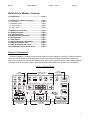
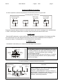
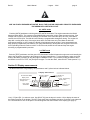
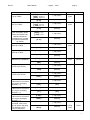
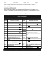
Be142
User's Manual
- August - 2014
page 1
AMF Controller Be142 User Manual
Be142 User’s Manual
The information in this document is subject to change without notice.
No part of this document may be copied or reproduced in any form or any means without the prior written
consent of Bernini Design company. Bernini Design assumes no responsibility for any errors which may appear
in this instruction manual or in the wiring diagrams.
Although Bernini Design has taken all possible steps to ensure that the User Manual is complete, bug free and
up-to-date, we accept that errors may occur. If you encounter problems with this instruction manual, please
contact us.
Customer Support BERNINI DESIGN SRL ITALY
e-mail: [email protected] or [email protected]
mobile 1: ++39 335 7077 148
mobile 2:++40 721 241 361
Warranty
Bernini Design SRL (hereinafter "BD") warrants that Be142 shall be free from defect in material or workmanship
for a period of 3 years from the BD delivery date. BD shall, at its option, repair or replace the product without
charge. BD shall return the Be142 to the buyer with the Default parameters at no extra charge. The buyer shall
furnish sufficient information on any alleged defects in the product, so as to enable BD to determine their cause
and existence. If the Be142 is not defective, or the product is defective for reason other than covered by this
warranty, the buyer will be charged accordingly. This warranty shall not apply if the Be142 has not been used in
accordance with the User Manual and other operating instruction, particularly if any defects are caused by
misuse, improper repair attempts, negligence in use or handling.
This equipment complies with the EMC protection requirements
WARNING!! High voltage is present inside the Be142. To avoid electric-shock hazard, operating
personnel must not remove the protective cover. Do not disconnect the grounding connection. The
Be142 can start the engine at anytime. Do not work on equipment, which is controlled by the Be142.
When servicing the engine, disconnect the battery and battery charger. We recommend that warning
signs be placed on equipment indicating the above.
1
Be142
User's Manual
- August - 2014
page 2
Be142 User's Manual - Contents
1.0 Introduction ...................................................... page 3
2.0 Selection of a Mode of operation ................... page 3
2.1 OFF mode ........................................................ page 3
2.2 MANUAL mode ............................................... page 3
2.3 AUTO mode .................................................... page 4
2.4 TEST mode ..................................................... page 4
3.0 Display measurements ................................... page 4
4.0 Display messages............................................ page 6
4.10 Alarm messages ............................................ page 6
4.20 Miscellaneous messages .............................. page 7
5.0 LED indicators ................................................. page 7
6.0 LOG Events ..................................................... page 7
7.0 Alarms, Warnings & Shutdowns .................... page 8
8.0 Automatic Periodic Test ................................. page 8
9.0 Panel & Genset builder notes ......................... page 8
10.0 Maintenance Timers Reset (Er.10) ............... page 8
Section 1.0 Introduction
The Be142 integrates a 3-Phase Automatic Mains Failure and a Generating Set controller. The Be142 provides
visual indication by means of LEDs and Display for Fuel Level, Engine & Electrical parameters, Alarms and
Status of the contactors. It features OFF-MAN-AUTO & TEST mode of operation and provides a RS485 interface
for remote control & monitoring. Figure 1 presents the panel layout. Be242 does not features serial interface.
Figure 1: Front Panel layout
Alarm
acknowledge
pushbutton
Display control
& indicators
Alarm
messages
F10
A
V
Hz / R.P.M.
Engine
h / Prog.
F8
F1
F2
Manual Engine
Control
F9
F3
F4
Contactors
Control
F5
F6
F7
Operating Mode
pushbuttons & LEDs
2
Be142
User's Manual
- August - 2014
page 3
Section 2.0 Mode of operation
A mode of operation is selected via pushbutton and indicated by means of a green LED:
Operating Modes Pusbuttons
Operating Modes
MANUAL Mode
green LED
MAN
Pushbutton
TEST Mode
green LED
AUTO Mode
green LED
OFF
OFF
TEST
TEST
AUTO
AUTO
Pushbutton
Pushbutton
Pushbutton
Every time the power supply is switched on, the Be142 returns to the “AUTO” operating mode, if the BE142 was
in TEST or AUTO prior to power down. In the other cases, the Be142 will enter the OFF mode.
2.1 OFF mode
Push the [OFF] pushbutton to enter the OFF mode. OFF mode clears the fault alarms. The Display and LEDs
are turned off and a dot on the display will blink slowly. Push one of the pushbuttons on the front panel to
energize the display. The display will turn off automatically after a few minutes.
2.2 MANUAL mode
The MANUAL mode allows you to manual control the Engine and Contactors.
Instructions
Manual Engine Control
Push the [MAN] pushbutton to select the MANUAL mode. Push
the [START] pushbutton until engine starts; the display indicates
the message [! ! ! !] during the preheat and the message [. . . .]
during the starting attempts.
When the engine is running, the green LED turns on. To stop the
engine, push the [STOP] pushbutton until the [StOP] message
appears on the display.
Engine Running
green LED
START
Pushbutton
STOP
Pushbutton
To control manually the contactors follow the instructions:
Contactors Control Panel
Generator
Presence LED
(Green)
KG-closed
indicator
(Green)
KM-closed
indicator
(Green)
KG
Instructions
Mains
Presence LED
(Green)
KM
KM
Pushbutton
(push to close)
KG
Pushbutton
(push to close)
Select the MANUAL mode, start the engine (see above)
and wait for voltage generator presence.
Push the [ I ] (KG) pushbutton to close the contactor of
the Generator. To transfer the Load to Mains, push the [I]
(KM) pushbutton (the [KG] will open). To open a
Contactor, push the [O] pushbutton.
[ O ]Pushbutton
(push to open)
3
Be142
User's Manual
- August - 2014
page 4
! ! WARNING ! !
LINE VOLTAGE IS EXPOSED WITHIN THE Be142, THE LOAD OR ANCILLARY CIRCUITRY EVEN WHEN
THE GREEN LEDs ARE TOTALLY OFF
2.3 AUTO mode
Push the [AUTO] pushbutton until the green LED ‘AUTO’ illuminates. The engine starts when the Be142
detects a Mains failure. The contactor of the MAINS (KM) opens after a delay. After the warm-up time, if the
Voltage and Frequency are within the settings, the contactor of the Generator (KG) will close. If the Mains
restores, the KG will open. The KM will close following a programmable changeover timing. The engine will
stop after a cooling down time. If the engine shuts down, the KM closes only if the Mains is within the
programmed settings. In AUTO mode, the Be142 will periodically test the engine if some parameters have
been properly programmed (ask details to your panel manufacturer). During this test, the green LED of the
AUTO operating mode will continue to blink. In AUTO mode, the Be142 can start and stop the engine
according to programmable inputs also.
2.4 TEST mode
Push the [TEST] pushbutton until the green LED illuminates.The Be142 starts the engine and could transfer the
load to the Generator according to the settings of the panel manufacturer. To stop the engine, select the AUTO
mode (if the Mains is present) or stop the engine in MANUAL mode. If you push the [STOP] pushbutton when
the Be142 is in AUTO or TEST, the [Er.09] will energize. To clear the alarm, select the OFF mode (section 7.0).
Section 3.0 Display measurements
The Be142 features a 4 Digit display, two pushbuttons and 5 yellow Leds as indicated below.
Display and Menus
Frequency-Speed
Display menu
Vac-Generator-Mains
Display menu
Generator-Current
Display menu
[ F8 ] control
Pushbutton
A
V
Hz / R.P.M.
Engine
F8
OIL-°C-%FUEL-Vb
Display menu
h-count - Programming
Display menu
h / Prog.
F9
[ F9 ]
Display control
Pushbutton
4Digit Display
Use [←F8] and [F9→] to select a menu. Use [ACK-F10] (see the layout in section 1.0) to display the name of
the function present on the display. The OFF mode shuts down the display and turns on the dot on the right side
of it. Push a button to turn on the panel. The following table lists the functions of the display (see page 5)
4
Be142
User's Manual
Display Function
Current of the Generator
(0 up to 1000A)
Voltage of the Generator
(60V up to 998V)
Voltage of the Mains
(60V up to 998V). When
Mains is simulated, the
display indicates the
message [U-on]. (contact
your panel manufacturer
for details)
Generator Frequency
(20Hz up to 70Hz)
Mains Frequency
(20Hz up to 70Hz)
- August - 2014
Display indications (*)
[AXXX] Ampere L1
[-XXX] Ampere L2
[_XXX] Ampere L3
[A -G]
[GXXX] Volt L1-L2
[-XXX] Volt L2-L3
[_XXX] Volt L1-L3
Pushbutton(s)
[U -G]
[ACK-F10]
[nXXX] (V R-S)
[-XXX] (V S-T)
[_XXX] (V T-R)
[←F8] or [F9→]
[U -on]
[ACK-F10]
[GXXX] Hz
[←F8] or [F9→]
[H - G]
[ACK-F10]
[nXXX] Hz
[←F8] or [F9→]
[H - n]
Speed
(600RPM up to 4000RPM)
Battery Voltage
(5,5 Vdc up to 36Vdc)
Charger Voltage
(3.0 Vdc up to 36Vdc)
[←F8] or [F9→]
[←F8] or [F9→]
Vac
menu
Yellow
Hz/RPM
menu
Yellow
Hz/RPM
menu
Yellow
(blinks)
Engine
Yellow
h/Prog
menu
Yellow
[ACK-F10]
[←F8] or [F9→]
[SPd]
[ACK-F10]
[←F8] or [F9→]
[batt]
[ACK-F10]
[cXX.X] Vdc
[←F8] or [F9→]
[Char.]
[ACK-F10]
Oil Pressure 0.0-20.0 Bar
(If the sensor is not used in
your engine, the display
indicates [----]).
[PXX.X] Bar
Temperature 0°-250 °C
(If the sensor is not used in
your engine, the display
indicates [----]).
[XXX °] °C
[ °C ]
[ACK]
Fuel Level % 0% - 99
(If the sensor is not used in
your engine, the display
indicates [----]).
h-meter up to 50,000h.
Over 9999, a dot on the
right will appear indicating
X10. Example [1234.]
means 12,340 hours.
[F XX] %
[←F8] or [F9→]
[FUEL]
[ACK-F10]
[XXXX] h
[←F8] or [F9→]
[Hour]
[ACK-F10]
[ bar ]
Menu & Led indicator
Aac
Yellow
menu
[ACK-F10]
[XXXX] RPM
[bXX.X] Vdc
page 5
[←F8] or [F9→]
[ACK]
[←F8] or [F9→]
5
Be142
User's Manual
- August - 2014
page 6
(*)NOTE: X indicates a numerical digit; if the measurement is not available the display will indicate [- - - -]
Section 4.0 Display messages
The Be142 shows alarms (table 4.10) and messages (table 4.20). The presence of alarms is indicated by the
blinking message [ALAr.]. Push the [→F9] pushbuttons to display the alarms one by one. Push the [←F8]
pushbutton to display additional information about the alarm. Push [ACK-F10] to silence the HORN (if provided).
Table 4.10: Alarm messages
( !!! ) NOTE: consult always your supplier or the user manual of the engine. A short description of the
alarms is indicated below.
Display
Description of the Alarm
Display
Description of the Alarm
[Er.01]
Over Frequency Shutdown
( !!! )
[Er. 14]
Low Oil Pressure Shutdown
[Er.02]
Engine Belt Break Shutdown
( !!! )
[Er. 15]
Temperature Switch Shutdown
[Er.03]
Remote LOCK Shutdown.
[Hi-C]
Over Current Shutdown or Warning.
[Er.04]
Alternator Failure Shutdown
( !!! )
[Hi-U]
Over Voltage / Under Voltage Shutdown
[Er.05]
Overload Warning or Shutdown
( °°° )
[Lo-U]
( °°° )
( !!! )
( !!! )
( °°° )
[InP.1]
[Er.06]
Under Frequency Shutdown
( °°° )
[InP.2]
[Er.07]
Fail To STOP Shutdown
( !!! )
[InP.3]
[Er.08]
Emergency Shutdown. (Wait for the end
of the Emergency condition before starting
the engine).
Emergency Shutdown from the Front
Panel. (Cancel the Alarm and restart the
engine).
Maintenance SERVICE warning ( !!! )
[Er.09]
[Er.10]
Fail To START Shutdown
[-oIL] (**)
[Er. 13]
Oil pressure warning or sensor failure.
( !!! )
[ -°C] (**)
Water temperature warning or sensor failure.
( !!! )
( !!! )
[FUEL]
(**)
[Er.12]
Normally these alarms protect your
Generator. Consult your supplier for further
details.
[InP.4]
SEE SECTION 10.0
[Er.11]
Input 1-2-3-4 Shutdown / Warning
Low Fuel Shutdown (Fill the tank and
restart the engine)
Battery Voltage Warning
( !!! )
[rEnt.]
[FAIL]
Fuel level warning (High or Low) or sensor
(Fill the tank and restart the engine)
Push [←F8] to display the remaining hours of
Rental contract.
There is an internal failure or memory error in
the Be142 controller
( !!! )
( °°° ) NOTE: verify if you are Overloading the Generator: consult an electrician.
l
6
Be142
User's Manual
- August - 2014
page 7
4.20 Miscellaneous messages
[rESt]
[n-on]
['''']
[StoP]
[U-uP]
[ dEL]
The Be142 is counting the rest time between
the starting attempts
MAINS simulated via an external switch.
The Be142 is performing the pre-glow.
The Be142 is stopping the engine.
Warm up time of the engine before closing the
contactor of the generator.
Delay time before cranking.
[. . . .]
[tEst]
[----]
[CooL]
The Be142 is cranking the engine.
The Be142 is in Test mode.
Measurement out of range or disabled.
The engine is running off load for
cooling.
Section 5.0 LED indicators
To test the LEDs and DISPLAY push the [OFF] pushbutton; the display turns off. Push and hold the [←F8]
and [F9→] pushbuttons simultaneously. The LEDs and DISPLAYs remain energised as long as the pushbuttons
are pressed and held together.
Section 6.0 LOG Events
To have access to the LOG events follow the instructions:
- Push the [OFF] button.
- Push and hold the [STOP] button until the message [Hist.] appears on display (approx. 10 seconds).
- Release the [STOP] button.
- Using [←F8] and [F9→] you can browse the events E01 up to E100.
- Push the [STOP] button to display the code of the EVENT (see table 4.10 for the meaning of the codes). The
message [----] indicates ‘No Event’ in the memory.
- To quit the LOG EVENTS push the [OFF] button.
Section 7.0 - Alarms, Warnings and Shutdowns
The Be142 features Shutdowns (the engine stops) and Warnings (the engine will continue to run) and provides:
A) - a general indication of alarm presence by means of the message [ALAr.] on the display
B) - symbols and ideograms on the front panel to indicate alarms (see Figure 1, section 1)
C) - display messages indicating warnings and shutdowns (see Table 4.10)
D) - a pushbutton to silence the Horn ([ACK-F10])
To silence the HORN (if provided by your Panel manufacturer), push the [ACK-F10] pushbutton.
To display details about the alarm, push the [←F8] pushbutton. To clear the alarm from the panel, remove the
cause of the alarm and then press the [OFF] pushbutton. The Table 4.10 in section 4.0 indicates all alarms.
!!! WARNING !!! In case of Alarm consult always your supplier or the user manual of the engine
7
Be142
User's Manual
- August - 2014
page 8
Section 8.0 Automatic Periodic Test
The Be142 does not use an internal real time clock for the programmed days of automatic test. Consult your
panel manufacturer to find out if Be142 is programmed with a Periodic Test. You could experiment with shifting
the periodic tests. To avoid error accumulation, we recommend the following procedure.
A) - Power off the controller (if a switch is provided by your panel manufacturer) or disconnect the battery.
B) - Connect the supply and select the 'AUTO' mode of operation.
The Be142 will start the engine after the programmed days. The engine will run OFF-LOAD for the time
programmed by your panel manufacturer. If the Mains fails during the Periodic Test, the Be142 will transfer the
load to the generator.
IMPORTANT NOTICE If the Vdc supply is removed, the Be142 looses the counts of the days. If the supply
restores, the Be142 starts to count the days from zero. To synchronize the periodic start follow the instruction of
the section 8.0
!! WARNING !!
High voltage is present inside the Be142. To avoid electric-shock hazard, operating personnel must not
remove the protective cover. Do not disconnect the grounding connection. The Be142 can start the
engine at anytime. Do not work on equipment, which is controlled by the Be142. When servicing the
engine, disconnect the battery and battery charger. We recommend that warning signs be placed on
equipment indicating the above.
9.0 - Panel & Gen-set Builders Notes
________________________________________
________________________________________
________________________________________
________________________________________
10.0 - MAINTENANCE TIMERS RESET
When a timer for the MAINTENANCE SERVICE expires, the Be142 indicates the message [Er.10] on display.
You can continue to use the generator but we recommend that you contact the genset manufacturer in order to
carry out the programmed maintenance. To clear the alarm, after making service, enter the MAN mode (see2.2),
push and hold the [ACK-F10] button for at least 20 seconds. The Be142 will restart the programmed timer for the
next MAINTENANCE SERVICE.
8