1
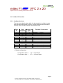
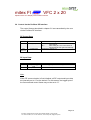
mitex FI
VFC 2 x 20
Alphanumeric VFC Display with Profibus Interface
User’s Manual
microSYST Systemelectronic GmbH, Albert-Einstein-Straße 7, 92637 Weiden
Tel +49 961 39166-0, Fax +49 961 39166-10, www.microsyst.de, [email protected]
mitex FI
VFC 2 x 20
Alphanumeric VFC Display with Profibus Interface
Table of Contents
1
GENERAL
4
2
SYSTEM OVERVIEW
5
3
TECHNICAL DATA
6
3.1
System or Device Start-Up
7
3.2
Performance in the Event of Error
7
3.3
Profibus DP Interface
3.3.1 Configuration data
3.3.2 Input Data
3.3.3 Output Data
3.3.4 Diagnosis Data
3.3.5 User Parameter Data
8
8
9
9
9
9
3.4
Control via the Profibus DP Interface
10
3.5
Control via the RS 232 Interface
11
3.6
Control Frames
3.6.1 Displaying an EEPROM Text
3.6.2 Displaying an Online Text
3.6.3 Displaying a Number
3.6.4 Writing Text to the EEPROM
3.6.5 Reading Text from the EEPROM
12
12
14
15
17
18
4
CONNECTOR PIN ASSIGNMENTS
19
5
HOUSING DIMENSIONS
23
5.1
Front Panel Cutout
24
5.2
Installation / Mounting
24
Page 2
microSYST Systemelectronic GmbH, Albert-Einstein-Straße 7, 92637 Weiden
Tel +49 961 39166-0, Fax +49 961 39166-10, www.microsyst.de, [email protected]
mitex FI
VFC 2 x 20
Alphanumeric VFC Display with Profibus Interface
6
APPENDIX
25
6.1
Standard Equipment
25
6.2
Maintenance and Care
25
6.3
Warranty / Liability
26
6.4
Declaration of Conformity
27
6.5
Font Table
6.5.1 European
6.5.2 Japanese
28
28
29
6.6
30
Versions Overview
Page 3
microSYST Systemelectronic GmbH, Albert-Einstein-Straße 7, 92637 Weiden
Tel +49 961 39166-0, Fax +49 961 39166-10, www.microsyst.de, [email protected]
mitex FI
VFC 2 x 20
Alphanumeric VFC Display with Profibus Interface
1 General
This bus compatible VFC monitor with Profibus DP interface has been
designed as a panel mount display for industrial applications.
The monitor consists of a vacuum fluorescent display. Two lines of text with
20 characters each can be displayed. Each character is displayed with a
resolution of 5 x 7 pixels. Character height is 10.5 mm (0.41 inches).
A physical RS 485 interface with Profibus DP protocol is used for serial
communication.
Predefined texts can be downloaded and saved to the display via the RS
232 interface.
Features:
•
•
•
•
•
Profibus DP interface
Text downloads via RS 232
Text memory (up to 255 texts with 40 characters each)
Metal DIN panel mount housing with special surface finish
Designed for use in industrial applications
Page 4
microSYST Systemelectronic GmbH, Albert-Einstein-Straße 7, 92637 Weiden
Tel +49 961 39166-0, Fax +49 961 39166-10, www.microsyst.de, [email protected]
mitex FI
VFC 2 x 20
Alphanumeric VFC Display with Profibus Interface
2 System Overview
The display (DP Slave) is connected to the DP master via Profibus.
Up to 127 Users
RS232Download
Profibus DP
Page 5
microSYST Systemelectronic GmbH, Albert-Einstein-Straße 7, 92637 Weiden
Tel +49 961 39166-0, Fax +49 961 39166-10, www.microsyst.de, [email protected]
VFC 2 x 20
mitex FI
Alphanumeric VFC Display with Profibus Interface
3 Technical Data
General Specifications
Display type:
Resolution:
Characters/lines:
Character height:
Display colour:
Operating voltage:
Power consumption:
Interfaces:
Baud rate:
Addresses:
Display:
Housing:
Housing dimensions:
Display area:
Mounting:
Protection:
Operating temp.:
Storage temperature:
vacuum fluorescent
5 x 7 pixels
2 lines of 20 characters each
10.5 mm (0.41 inches)
cyan
24 VDC ± 20%, protected against polarity reversal
300 mA at 24 VDC operating voltage
Bus: Profibus DP
Download: RS 232
9.6 kBaud to 12 Mbaud
0 to 126
ASCII character set + additional characters
(see table in chapter “appendix”)
DIN panel-mount housing,
metal with special surface finish
see chapter 5
147 x 29 mm (5.79 x 1.14 inches)
screw clamps
front panel: IP65
0 to +50° C
–25 to +60 °C
Page 6
microSYST Systemelectronic GmbH, Albert-Einstein-Straße 7, 92637 Weiden
Tel +49 961 39166-0, Fax +49 961 39166-10, www.microsyst.de, [email protected]
mitex FI
VFC 2 x 20
Alphanumeric VFC Display with Profibus Interface
3.1 System or Device Start-Up
After supply power has been switched on, the green “RUN” LED starts
blinking and the power-up message is displayed. This message includes
the device designation, the selected DP address and the number of
texts stored in memory.
As soon as DP communication is initialised, the power-up message
disappears and the yellow “BUS” LED is illuminated continuously.
After DP communication has been ended, the power-up message
reappears and the yellow “BUS” LED goes out.
DP communication may not be active when texts are being downloaded
(via the RS 232 interface)!
After text downloading has been completed, DP communication can be
reactivated.
3.2 Performance in the Event of Error
DP communication is not possible in the event of a faulty Profibus
connection, and the yellow “BUS” LED does not light up. Please check
for correct wiring to the Profibus interface in this case (bus termination
etc.). In addition, make sure that the selected device address (DIP
switch setting) is correct, and that input and output data lengths are
within the allowable limits.
If the integrated microcontroller malfunctions, the red “ERROR” LED
blinks. Make sure that supply voltage tolerances are complied with in
this case.
If the above described remedies do not eliminate the respective error,
please return the device for repair.
Page 7
microSYST Systemelectronic GmbH, Albert-Einstein-Straße 7, 92637 Weiden
Tel +49 961 39166-0, Fax +49 961 39166-10, www.microsyst.de, [email protected]
VFC 2 x 20
mitex FI
Alphanumeric VFC Display with Profibus Interface
3.3 Profibus DP Interface
3.3.1 Configuration data
The user can adapt the data width for data transfer to individual needs
with the data configuration function. Various identifiers are required to
this end, which can be entered in any desired order.
Byte
No.
Data
Identifier
10h
11h
12h
Number of
Bytes
1
2
3
input data,
input data,
input data,
1 byte
2 bytes
3 bytes
1
2
:
16
output data,
output data,
x
20h
21h
:
2Fh
1 byte
2 bytes
:
16 bytes
x
x
x
30h
31h
32h
1/1
2/2
3/3
input / output data, 1 byte each
input / output data, 2 bytes each
input / output data, 3 bytes each
x
x
x
x
x
Function / Description
output data,
Default configuration:
Configuration byte 0:
Configuration byte 1:
12h = 3 input bytes
2Fh = 16 output bytes
Page 8
microSYST Systemelectronic GmbH, Albert-Einstein-Straße 7, 92637 Weiden
Tel +49 961 39166-0, Fax +49 961 39166-10, www.microsyst.de, [email protected]
mitex FI
VFC 2 x 20
Alphanumeric VFC Display with Profibus Interface
3.3.2 Input Data
The device supports input data which have been configured to the
length selected during configuration. The minimum number of input data
is 0 bytes, and the maximum number is 3 bytes.
3.3.3 Output Data
The device supports output data which have been configured to the
length selected during configuration. The minimum number of output
data is 0 bytes, and the maximum number is 47 bytes.
3.3.4 Diagnosis Data
The device does not support any extended diagnosis data. The default
diagnosis is used.
3.3.5 User Parameter Data
User parameter data are not supported by the device. However, a test is
run to determine if user parameter data are transferred by the Profibus
master. If parameter data are transferred, Profibus initialisation is
disabled and the slave’s parameters must be reconfigured.
Note:
Standard parameters configuration is required and is normally installed
by the utilised DP configurators.
Page 9
microSYST Systemelectronic GmbH, Albert-Einstein-Straße 7, 92637 Weiden
Tel +49 961 39166-0, Fax +49 961 39166-10, www.microsyst.de, [email protected]
mitex FI
VFC 2 x 20
Alphanumeric VFC Display with Profibus Interface
3.4 Control via the Profibus DP Interface
The control frames described in chapter 3.6 are transmitted by the user
via the Profibus DP interface.
DP Output Data:
Index
0
Content
Toggle byte
1 to
max. 46
Control frame
Significance
Bits 0 to 6: The control frame is executed once for
each change.
Bit 7:
After setting bit 7, the control frame is
executed again and again automatically.
as defined in chapter 3.6
DP Input Data:
Index
0
1 to 2
Content
Response toggle
byte
Response frame
Significance
Same as toggle byte after executing the frame
As defined in chapter 3.6
Note:
When DP communication is first initialised, all DP output and input data
are internally set to “0” at the device! For this reason, the toggle byte of
the first executed control frame may not be set to “0”.
Page 10
microSYST Systemelectronic GmbH, Albert-Einstein-Straße 7, 92637 Weiden
Tel +49 961 39166-0, Fax +49 961 39166-10, www.microsyst.de, [email protected]
mitex FI
VFC 2 x 20
Alphanumeric VFC Display with Profibus Interface
3.5 Control via the RS 232 Interface
The control frames described in chapter 3.6 are transmitted via the
RS 232 interface by the included PC program.
It must be assured that the pause between the individual frame bytes
included in the control frame does not exceed 3 ms during transmission.
The end of the frame is identified by means of a pause of at least 5 ms.
The display unit transmits the response frame immediately after
execution of the command.
Page 11
microSYST Systemelectronic GmbH, Albert-Einstein-Straße 7, 92637 Weiden
Tel +49 961 39166-0, Fax +49 961 39166-10, www.microsyst.de, [email protected]
VFC 2 x 20
mitex FI
Alphanumeric VFC Display with Profibus Interface
3.6 Control Frames
The control frames used for controlling the display unit are defined
below.
These frames are transmitted by the user via the Profibus DP interface,
and by the included PC program via the RS 232 interface.
3.6.1 Displaying an EEPROM Text
Control frame:
Index
RS 232 / DP
0/1
1/2
Content
“T” = 54h
Attribute
2/3
Mode
3/4
4/5
5/6
6/7
X position
Y position
Text number
Text number
Significance
“Display EEPROM text”
Bit 0 = 0:
reserved
Bit 1 = 1:
blinking text display
Bits 2 to 7 = 0: reserved
0 = display all characters
1 = display all characters after clearing the display
2 = display all characters except for blanks (20h)
3 = display all characters except for blanks (20h) after
clearing the display
0 (left) to 19 (right): X position of the first character
0 (top) to 1 (bottom): Y position of the first character
(0 to 65535): LOW byte
(0 to 65535): HIGH byte
Response frame:
Index
RS232 / DP
0/1
1/2
Content
“T” = 54h
Error code
Significance
“Display EEPROM text”
“0” = 30h: no error
“1” = 31h: error occurred
Page 12
microSYST Systemelectronic GmbH, Albert-Einstein-Straße 7, 92637 Weiden
Tel +49 961 39166-0, Fax +49 961 39166-10, www.microsyst.de, [email protected]
mitex FI
VFC 2 x 20
Alphanumeric VFC Display with Profibus Interface
Note:
At the end of each line, a line break occurs to the first column of the
next line, or the first line.
Example:
Display EEPROM text number 1025d (= 0401h) in normal display mode
at the default position.
DP control frame: 54h, 00h, 00h, 00h, 00h, 01h, 04h
For control via Profibus DP, it is advisable to set bit 7 of the toggle byte
in this case. Only the text number must then be changed (DP indices 6
and 7) in order to display a different text.
Page 13
microSYST Systemelectronic GmbH, Albert-Einstein-Straße 7, 92637 Weiden
Tel +49 961 39166-0, Fax +49 961 39166-10, www.microsyst.de, [email protected]
VFC 2 x 20
mitex FI
Alphanumeric VFC Display with Profibus Interface
3.6.2 Displaying an Online Text
Control frame:
Index
RS 232 / DP
0/1
1/2
Content
“O” = 4Fh
Attribute
2/3
Mode
3/4
4/5
5/6
6 / 7 to
max. 45 / 46
X position
Y position
Text length
Text
Significance
“Display online text”
Bit 0 = 0:
reserved
Bit 1 = 1:
blinking text display
Bits 2 to 7 = 0: reserved
0 = display all characters
1 = display all characters after clearing the display
2 = display all characters except for blanks (20h)
3 = display all characters except for blanks (20h) after
clearing the display
0 (left) to 19 (right): X position of the first character
0 (top) to 1 (bottom): Y position of the first character
1 to 40 characters
ASCII characters 0 to 255 (see character set table in the
appendix)
Response frame:
Index
RS232 / DP
0/1
1/2
Content
“O” = 4Fh
Error code
Significance
“Display online text”
“0” = 30h: no error
“1” = 31h: error occurred
Note:
At the end of each line, a line break occurs to the first column of the
next line, or the first line.
Example:
Display “ABC” at position X = 10 and Y = 1 (blinking display, clear
display first)
Page 14
microSYST Systemelectronic GmbH, Albert-Einstein-Straße 7, 92637 Weiden
Tel +49 961 39166-0, Fax +49 961 39166-10, www.microsyst.de, [email protected]
VFC 2 x 20
mitex FI
Alphanumeric VFC Display with Profibus Interface
DP control frame:
01h (previously 00h), 4Fh, 02h, 01h, 0Ah, 01h, 03h, 41h, 42h, 43h
The toggle byte must be changed last in this case, in order to initialise
execution of the command.
3.6.3 Displaying a Number
Control frame:
Index
RS 232 / DP
0/1
1/2
Content
“Z” = 5Ah
Attribute
2/3
Mode
3/4
4/5
5/6
X position
Y position
Data format
6/7
Display
format
7/8
8/9
Number of
places
Layout
9 / 10
10 / 11
11 / 12
12 / 13
Number
Number
Number
Number
Significance
“Display number”
Bit 0 = 0:
reserved
Bit 1 = 1:
blinking text display
Bits 2 to 7 = 0: reserved
0 = display all characters
1 = display all characters after clearing the display
2 = display all characters except for blanks (20h)
3 = display all characters except for blanks (20h) after
clearing the display
0 (left) to 19 (right): X position of the first character
0 (top) to 1 (bottom): Y position of the first character
0 = “unsigned char” value: [9/10]
1 = “unsigned int” value: [9/10] = LSB, [10/11] = MSB
2 = “unsigned long” value: [9/10] = LSB, ..., [12/13] = MSB
3 = “signed char” value:
[9/10]
4 = “signed int” value:
[9/10] = LSB, [10/11] = MSB
5 = “signed long” value:
[9/10] = LSB, ..., [12/13] = MSB
(“signed” values in two’s compliment representation)
0 = decimal representation: “-” or precede with “ ”
1 = decimal representation: “-”or precede with “+”
2 = hexadecimal representation
1 to 8 displayed places (decimal representation, unused
places = blanks (20h), plus or minus sign included)
0 = right-justified representation
1 = left-justified representation
Valence 2^0 (LSB = least significant byte)
Valence 2^8
Valence 2^16
Valence 2^24 (MSB = most significant byte)
Page 15
microSYST Systemelectronic GmbH, Albert-Einstein-Straße 7, 92637 Weiden
Tel +49 961 39166-0, Fax +49 961 39166-10, www.microsyst.de, [email protected]
VFC 2 x 20
mitex FI
Alphanumeric VFC Display with Profibus Interface
Response frame:
Index
RS232 / DP
0/1
1/2
Content
“Z” = 5Ah
Error code
Significance
“Display number”
“0” = 30h: no error
“1” = 31h: error occurred
Note:
At the end of each line, a line break occurs to the first column of the
next line, or the first line.
Example:
Display decimal number with plus or minus sign (“signed int” value) =
-1234d (= FB2Eh).
DP control frame:
80h, 5Ah, 00h, 00h, 00h, 00h, 04h, 00h, 05h, 00h, 2Eh, FBh
After entering DP indices 1 through 11, DP index 0 (toggle byte) is set to
80h. If another value needs to be displayed subsequently, only the
number needs to be changed (indices 10 and 11).
Page 16
microSYST Systemelectronic GmbH, Albert-Einstein-Straße 7, 92637 Weiden
Tel +49 961 39166-0, Fax +49 961 39166-10, www.microsyst.de, [email protected]
VFC 2 x 20
mitex FI
Alphanumeric VFC Display with Profibus Interface
3.6.4 Writing Text to the EEPROM
Control frame:
Index RS 232
Content
0
“S” = 53h
1
Memory location (0 to 255)
2
Memory location (0 to 255)
3
Text number (0 to 65535)
4
Text number (0 to 65535)
5 to 44
Text (ASCII encoded)
Significance
“Write text to EEPROM”
LOW byte
HIGH byte (always 0)
LOW byte
HIGH byte
st
nd
40 bytes (1 line 20 bytes, 2 line 20 bytes)
Response frame:
Index RS232
0
1
Content
“S” = 53h
Error code
Significance
“Write text to EEPROM”
“0” = 30h: no error
“1” = 31h: error occurred
Notes:
• Memory location 0:
text number
Text
= number of existing texts
(1 to 255 permitted)
= not used
• Texts must be saved to the memory locations sorted according to
text number (lowest text number at memory location 1).
• This command may only be executed via the RS 232 interface!
• This frame has no significance for the user. It is used by the PC
software only.
Page 17
microSYST Systemelectronic GmbH, Albert-Einstein-Straße 7, 92637 Weiden
Tel +49 961 39166-0, Fax +49 961 39166-10, www.microsyst.de, [email protected]
VFC 2 x 20
mitex FI
Alphanumeric VFC Display with Profibus Interface
3.6.5 Reading Text from the EEPROM
Control frame:
Index RS 232
0
1
2
Content
“L” = 4Ch
Memory location (0 to 255)
Memory location (0 to 255)
Significance
“Read text from EEPROM”
LOW byte
HIGH byte (always 0)
Response frame:
Index RS232
0
1
Content
“L” = 4Ch
Error code
2
Text number
(0 to 65535)
Text number
(0 to 65535)
Text (ASCII
encoded)
3
4 to 43
Significance
“Read text from EEPROM”
“0” = 30h: no error
“1” = 31h: error occurred
LOW byte
HIGH byte
st
40 bytes (1 line 20 bytes, 2
nd
line 20 bytes)
Notes:
• Memory location 0:
text number
Text
= number of existing texts
(1 to 255)
= not used
• In the event of an error, only the error code is returned (indices 2 to
43 do not apply).
• This command may only be executed via the RS 232 interface!
• This frame has no significance for the user. It is used by the PC
software only.
Page 18
microSYST Systemelectronic GmbH, Albert-Einstein-Straße 7, 92637 Weiden
Tel +49 961 39166-0, Fax +49 961 39166-10, www.microsyst.de, [email protected]
VFC 2 x 20
mitex FI
Alphanumeric VFC Display with Profibus Interface
4 Connector Pin Assignments
Download RS232 (9-pin sub-miniature plug connector):
Pin
1
2
3
4
5
6
7
8
9
Download RS232
n.c.
RxD
TxD
n.c.
GND
n.c.
n.c.
n.c.
n.c.
Connection mitex - PC
RxD
TxD
GND
mitex
PC
Pin
2
3
5
Pin
2
3
5
RxD
TxD
GND
Page 19
microSYST Systemelectronic GmbH, Albert-Einstein-Straße 7, 92637 Weiden
Tel +49 961 39166-0, Fax +49 961 39166-10, www.microsyst.de, [email protected]
VFC 2 x 20
mitex FI
Alphanumeric VFC Display with Profibus Interface
Profibus DP (9-pin sub-miniature socket connector):
Pin
1
2
3
4
5
6
7
8
9
Profibus DP
n.c.
n.c.
Rx+ / Tx+
RTS
GND ext.*
+5 VDC ext.*
n.c.
Rx- / Txn.c.
*only for bus termination
Power
Pin
1
2
3
Power
+24 VDC
GND
PE
LEDs
Designation
BUS (yellow)
RUN (green)
ERROR (red)
Description
Continuously illuminated during DP communication
Blinks at approx. 2 Hz
(for monitoring microcontroller functioning)
Blinks if the microcontroller cannot be initialised correctly
(e.g. poor supply power quality).
Page 20
microSYST Systemelectronic GmbH, Albert-Einstein-Straße 7, 92637 Weiden
Tel +49 961 39166-0, Fax +49 961 39166-10, www.microsyst.de, [email protected]
mitex FI
VFC 2 x 20
Alphanumeric VFC Display with Profibus Interface
DIP-Switch 1
DIP
6
ON
Japanese
character set*
OFF
European
character set*
DIP switches 1 to 5, 7 and 8 are reserved (=OFF) and must not be changed.
*see chapter “Font Table”
Page 21
microSYST Systemelectronic GmbH, Albert-Einstein-Straße 7, 92637 Weiden
Tel +49 961 39166-0, Fax +49 961 39166-10, www.microsyst.de, [email protected]
mitex FI
VFC 2 x 20
Alphanumeric VFC Display with Profibus Interface
DIP Switch 2
DIP
1
2
3
4
5
6
7
8
9
10
Function
0
ID no.: 2
1
ID no.: 2
2
ID no.: 2
3
ID no.: 2
4
ID no.: 2
5
ID no.: 2
6
ID no.: 2
Reserved
Bus termination
Bus termination
ON
1D
2D
4D
8D
16D
32D
64D
Not allowed
set
set
OFF
0
0
0
0
0
0
0
Must be set to „OFF“
not set
not set
Allowable DP addresses: 0 to 126
PE
This connector serves for the earth connection.
Page 22
microSYST Systemelectronic GmbH, Albert-Einstein-Straße 7, 92637 Weiden
Tel +49 961 39166-0, Fax +49 961 39166-10, www.microsyst.de, [email protected]
VFC 2 x 20
mitex FI
Alphanumeric VFC Display with Profibus Interface
5 Housing Dimensions
Designation
Dimension in mm
Dimension in inches
B
216
8.50
H
96
3.78
D
206
8.11
E
86
3.39
T
42
1.65
Page 23
microSYST Systemelectronic GmbH, Albert-Einstein-Straße 7, 92637 Weiden
Tel +49 961 39166-0, Fax +49 961 39166-10, www.microsyst.de, [email protected]
VFC 2 x 20
mitex FI
Alphanumeric VFC Display with Profibus Interface
5.1 Front Panel Cutout
e
R 0.8 mm (0.03’’) max.
min. 10 mm (0.39’’)
e
R 0.8 mm (0.03’’) max.
d
Designation
Dimension in mm
Dimension in inches
d
207
8.15
e
87
3.43
5.2 Installation / Mounting
The device has been designed for mounting to a panel. The tabs
provided to this end are bent up to enable fastening of the clamps after
the device has been inserted into the panel cutout.
A rubber gasket makes a watertight seal between the device’s front
panel and the control panel (IP65).
Rubber Gasket
Rubber
Gasket
Housing
Housing
Fastening Clamp
Front Panel
Front Panel
Control Panel
Control Panel
Page 24
microSYST Systemelectronic GmbH, Albert-Einstein-Straße 7, 92637 Weiden
Tel +49 961 39166-0, Fax +49 961 39166-10, www.microsyst.de, [email protected]
mitex FI
VFC 2 x 20
Alphanumeric VFC Display with Profibus Interface
6 Appendix
6.1 Standard Equipment
•
•
•
•
•
•
Display in the current software and hardware versions
Mounting kit (M4 screw clamps)
Sealing frame
User’s manual
PC software on floppy disk
Floppy disk with DDBF.
6.2 Maintenance and Care
Observe the following instructions in order to assure best possible
performance of the display:
•
The display must be switched off before cleaning. Only solvent-free
cleaners may be used, because plastic components may otherwise
be damaged. Under no circumstances may moisture be allowed to
enter the interior of the device during cleaning.
•
Protect the display from excessive humidity, extreme vibration,
direct sunlight and extreme temperatures. Non-observance may
lead to malfunctioning or destruction of the device. Under certain
circumstances electrical shock, fire and explosion may occur as
well. Information concerning allowable ambient conditions, in
particular recommended temperature and atmospheric humidity
ranges, can be found in the chapter entitled “Technical Data”.
•
The display may not be placed into service if the device and/or the
power cable are known to be damaged.
•
Do not attempt to open or repair the device yourself. The guarantee
is rendered null and void if the device is tampered with by
unauthorised persons.
•
Observe all notes and instructions included in this user’s manual.
Page 25
microSYST Systemelectronic GmbH, Albert-Einstein-Straße 7, 92637 Weiden
Tel +49 961 39166-0, Fax +49 961 39166-10, www.microsyst.de, [email protected]
mitex FI
VFC 2 x 20
Alphanumeric VFC Display with Profibus Interface
6.3 Warranty / Liability
For the product, liability is assumed for defects, which existed at the
delivery date according to our General Terms and Conditions.
Technically changes as well as errors are excepted. A claim for delivery
of a new product does not exist. The buyer has to check the received
product immediately and indicate evident defects at the latest 24 hours
after detection. Non-observance of notification requirements is equated
with acceptance of the defect. Not immediately visible defects have to
be indicated immediately after their perception too.
Generally, defects and their symptoms must be described as accurately
as possible in order to allow for reproducibility and elimination. The
buyer must provide for access to the relevant device and all required
and/or useful information at no charge and must make all of the required
data and machine time available free of charge.
The guarantee does not cover defects, which result from nonobservance of the prescribed conditions of use, or from improper
handling.
If the device has been placed at the disposal of the buyer for test
purposes and has been purchased subsequent to such testing, both
parties agree that the product is to be considered “used” and that it has
been purchased “as is”. No guarantee claims may be made in such
cases.
The General Terms and Conditions of microSYST Systemelectronic
GmbH in current version apply as well.
Page 26
microSYST Systemelectronic GmbH, Albert-Einstein-Straße 7, 92637 Weiden
Tel +49 961 39166-0, Fax +49 961 39166-10, www.microsyst.de, [email protected]
VFC 2 x 20
mitex FI
Alphanumeric VFC Display with Profibus Interface
6.4 Declaration of Conformity
EG-Konformitätserklärung
Declaration of EC-Conformity
Produktbezeichnung:
Product name:
mitex FI DP VFC 2 x 20
Produktbeschreibung:
Product description:
Alphanumerische VFC-Anzeige mit Profibus-Interface /
Alphanumeric VFC Display with Profibus Interface
Hersteller:
Manufacturer:
microSYST Systemelectronic GmbH
Albert-Einstein-Straße 7
92637 Weiden
Das bezeichnete Produkt stimmt mit
der folgenden Europäischen Richtlinie
überein:
We herewith confirm that the above
mentioned product meets the
requirements of the following standard:
Die Übereinstimmung des bezeichneten
Produktes mit den Vorschriften der
Richtlinie wird nachgewiesen durch die
vollständige Einhaltung folgender Normen:
The correspondence of the above mentioned
product with these requirements is proved by
the fact that these products meet with the
following single standards:
Nummer
Europäische Norm
EN61000-6-2:2006
EN61000-6-4:2007
2004/108/EG
Bezeichnung
Elektromagnetische
Verträglichkeit (EMV)
Weiden, den 04.04.13
Harald Kilian
Leiter operatives Geschäft / COO
Prokurist / Authorized Signatory
Page 27
microSYST Systemelectronic GmbH, Albert-Einstein-Straße 7, 92637 Weiden
Tel +49 961 39166-0, Fax +49 961 39166-10, www.microsyst.de, [email protected]
mitex FI
VFC 2 x 20
Alphanumeric VFC Display with Profibus Interface
6.5 Font Table
6.5.1 European
Page 28
microSYST Systemelectronic GmbH, Albert-Einstein-Straße 7, 92637 Weiden
Tel +49 961 39166-0, Fax +49 961 39166-10, www.microsyst.de, [email protected]
mitex FI
VFC 2 x 20
Alphanumeric VFC Display with Profibus Interface
6.5.2 Japanese
Page 29
microSYST Systemelectronic GmbH, Albert-Einstein-Straße 7, 92637 Weiden
Tel +49 961 39166-0, Fax +49 961 39166-10, www.microsyst.de, [email protected]
mitex FI
VFC 2 x 20
Alphanumeric VFC Display with Profibus Interface
6.6 Versions Overview
Ver.
1.00
1.10
1.20
1.30
1.40
Date
4/11/2003
1/19/2006
4/30/2009
4/4/2013
10/23/2013
Comments, Description
Kreuzer
Kreuzer: Chapter „Declaration of Conformity“ added
Kreuzer: DIP switch 1, DIP8 and DIP9 always in OFF position
Company address, declaration of conformity, warranty
Logo
Certified per DIN EN ISO 9001.
Page 30
microSYST Systemelectronic GmbH, Albert-Einstein-Straße 7, 92637 Weiden
Tel +49 961 39166-0, Fax +49 961 39166-10, www.microsyst.de, [email protected]