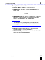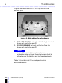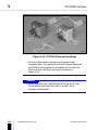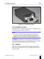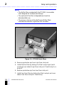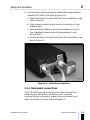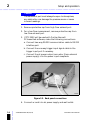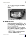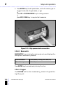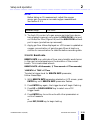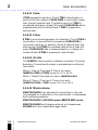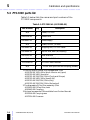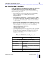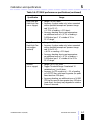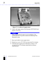
1
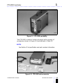
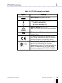
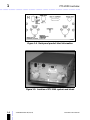
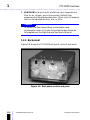
PTS 2000 ................................................... Version 4.0 User’s Manual Operators Manual .................................................................... Copyright © Puritan-Bennett Corporation 1999, 2003. All rights reserved. The information contained in this manual is the sole property of Puritan Bennett and may not be reproduced or copied without the permission of the Company. This manual may be revised or replaced by Puritan Bennett at any time and without notice. Users always should ensure that they have the most current version applicable to their equipment. While the information set forth herein is believed to be accurate, it is not a substitute for the exercise of professional judgement. The equipment described in this document should only be used by trained professionals. Puritan Bennett’s sole responsibility with respect to such equipment, and its use, is as stated in the limited warranty provided with such equipment. Nothing in this manual shall limit or restrict in any way Puritan Bennett’s right to revise or otherwise change or modify the equipment described herein, without notice. In the absence of an express, written agreement to the contrary, Puritan Bennett has no obligation to furnish any such revision, changes, or modifications to the owner or user of the equipment described herein. ii ....... Manufactured for Puritan-Bennett Corporation 4280 Hacienda Drive Pleasanton, CA 94588 USA Toll Free: 1.800.635.5267 4-076180-00 Rev. B (07/03) Authorized Representative Tyco Healthcare UK LTD 154 Fareham Road Gosport PO13 0AS, U.K. PTS 2000 User’s Manual .................................................................... Definitions This manual uses the following special indicators to convey information of a specific nature: Warning Indicates a condition that can endanger operator or service person. Caution Indicates a condition that can damage the equipment. NOTE: Indicates points of particular emphasis that make operation of the PTS 2000 more efficient or convenient. Warnings, cautions, and notes Please take the time to familiarize yourself with the following safety considerations, special handling requirements, and regulations that govern the use of the Performance Test System PTS 2000. Warning Possible explosion hazard if used in the presence of flammable anesthetics. Warning 4-076180-00 Rev. B (07/03) PTS 2000 User’s Manual ....... ELECTRICAL SHOCK HAZARD: Only qualified and trained personnel are authorized to service the PTS 2000 or replace the unit’s O2 sensor. Use only factory-approved parts and procedures to service this instrument. Contact Puritan Bennett service personnel for further information. iii .................................................................... Caution Be sure the inlet and exhaust ports are not obstructed, and any connecting hoses are not kinked. Obstructing ports and hoses can cause inaccurate readings. Caution Always use dry gas; humidified gas will affect the accuracy of flow measurements. Caution Always use the Re/Flex or D/Flex filter assembly (or equivalent) in-line in the high-flow inlet hose; if the filter is not used correctly, performance can be impaired. Caution Always cap the flowmeter inlets and outlets when the instrument is transported or not in use. Warning Grounding reliability can be achieved only when the equipment is connected to a receptacle marked “HOSPITAL GRADE.” Serialization The PTS 2000 test instrument has a unique serial number that is used to track calibration dates and identify the unit’s year of manufacture. Customer assistance iv ....... For further assistance contact your local Puritan Bennett representative. 4-076180-00 Rev. B (07/03) PTS 2000 User’s Manual .................................................................... Preface This manual provides information needed to operate the Performance Test System PTS 2000 and is intended for use by certified biomedical engineering technicians or personnel with equivalent experience and training in using this type of equipment. 4-076180-00 Rev. B (07/03) PTS 2000 User’s Manual ....... The O2 sensor is the only field replaceable unit (FRU) on the PTS 2000; all additional service requirements, including system calibration, must be performed by the manufacturer. v vi ....... .................................................................... 4-076180-00 Rev. B (07/03) PTS 2000 User’s Manual Contents ................................................................... Section 1 PTS 2000 overview 1.1 Introduction . . . . . . . . . . . . . . . . . . . . . . . . . . . . . . . . . . . 1-1 1.2 Hardware overview. . . . . . . . . . . . . . . . . . . . . . . . . . . . . . 1-2 1.2.1 Controls and ports . . . . . . . . . . . . . . . . . . . . . . . . . . 1-4 1.2.2 Symbols and labels . . . . . . . . . . . . . . . . . . . . . . . . . . 1-4 1.2.3 Front panel. . . . . . . . . . . . . . . . . . . . . . . . . . . . . . . . 1-7 1.2.4 Back panel . . . . . . . . . . . . . . . . . . . . . . . . . . . . . . . 1-10 1.2.5 Filters . . . . . . . . . . . . . . . . . . . . . . . . . . . . . . . . . . . 1-13 1.2.6 Operational controls . . . . . . . . . . . . . . . . . . . . . . . . 1-15 1.2.7 Cleaning. . . . . . . . . . . . . . . . . . . . . . . . . . . . . . . . . 1-15 1.3 Electrical connections . . . . . . . . . . . . . . . . . . . . . . . . . . . 1-16 Section 2 Setup and operation 4-076180-00 Rev. B (07/03) PTS 2000 User’s Manual ....... 2.1 PTS 2000 setup . . . . . . . . . . . . . . . . . . . . . . . . . . . . . . . . 2-1 2.1.1 Front panel connections . . . . . . . . . . . . . . . . . . . . . . 2-1 2.1.2 Back panel connections . . . . . . . . . . . . . . . . . . . . . . 2-3 2.2 Operator interface . . . . . . . . . . . . . . . . . . . . . . . . . . . . . . 2-5 2.3 Operational overview . . . . . . . . . . . . . . . . . . . . . . . . . . . . 2-5 2.4 Powerup and warmup . . . . . . . . . . . . . . . . . . . . . . . . . . . 2-6 2.5 Tester functions . . . . . . . . . . . . . . . . . . . . . . . . . . . . . . . . 2-7 2.5.1 Parameters and screens . . . . . . . . . . . . . . . . . . . . . . 2-7 2.5.2 Trigger levels . . . . . . . . . . . . . . . . . . . . . . . . . . . . . . 2-9 2.5.3 Optional units of measure. . . . . . . . . . . . . . . . . . . . 2-10 2.5.4 Remote operation mode. . . . . . . . . . . . . . . . . . . . . 2-10 2.5.4.1 High flow . . . . . . . . . . . . . . . . . . . . . . . . . . . . 2-11 2.5.4.2 Peak high flow . . . . . . . . . . . . . . . . . . . . . . . . . 2-12 2.5.4.3 Low pressure . . . . . . . . . . . . . . . . . . . . . . . . . . 2-12 2.5.4.4 Peak low pressure . . . . . . . . . . . . . . . . . . . . . . 2-14 2.5.4.5 Volume . . . . . . . . . . . . . . . . . . . . . . . . . . . . . . 2-15 2.5.4.6 Low flow . . . . . . . . . . . . . . . . . . . . . . . . . . . . . 2-16 2.5.4.7 High pressure . . . . . . . . . . . . . . . . . . . . . . . . . 2-17 vii .................................................................... 2.5.4.8 Barometric . . . . . . . . . . . . . . . . . . . . . . . . . . . 2-18 2.5.4.9 Oxygen . . . . . . . . . . . . . . . . . . . . . . . . . . . . . . 2-18 2.5.4.10 Breath rate . . . . . . . . . . . . . . . . . . . . . . . . . . 2-19 2.5.4.11 I time . . . . . . . . . . . . . . . . . . . . . . . . . . . . . . 2-20 2.5.4.12 E time . . . . . . . . . . . . . . . . . . . . . . . . . . . . . . 2-20 2.5.4.13 I:E ratio . . . . . . . . . . . . . . . . . . . . . . . . . . . . . 2-20 2.5.4.14 Minute volume . . . . . . . . . . . . . . . . . . . . . . . 2-20 2.5.5 Summary of tester functions and options . . . . . . . . . 2-21 Section 3 Auxiliary menu 3.1 Purpose and functions . . . . . . . . . . . . . . . . . . . . . . . . . . . . 3-1 3.1.1 Oxygen calibration . . . . . . . . . . . . . . . . . . . . . . . . . . 3-1 3.1.2 Flow compare . . . . . . . . . . . . . . . . . . . . . . . . . . . . . . 3-3 3.1.3 Default tests. . . . . . . . . . . . . . . . . . . . . . . . . . . . . . . . 3-5 3.1.4 Clear all tests . . . . . . . . . . . . . . . . . . . . . . . . . . . . . . . 3-6 3.1.5 Edit mode access . . . . . . . . . . . . . . . . . . . . . . . . . . . . 3-8 Section 4 Secondary functions 4.1 Clearing data . . . . . . . . . . . . . . . . . . . . . . . . . . . . . . . . . . . 4-1 4.1.1 Zero high pressure . . . . . . . . . . . . . . . . . . . . . . . . . . . 4-1 4.1.2 Zero low pressure . . . . . . . . . . . . . . . . . . . . . . . . . . . 4-1 4.1.3 Clearing breathing parameters and peak values . . . . . . . . . . . . . . . . . . . . . . . . . . . . . . . . . . . 4-2 Section 5 Calibration and specifications ....... 5.1 PTS 2000 calibration . . . . . . . . . . . . . . . . . . . . . . . . . . . . . 5-1 5.1.1 Certificate of calibration . . . . . . . . . . . . . . . . . . . . . . . 5-1 5.1.2 Recalibration notification . . . . . . . . . . . . . . . . . . . . . . 5-2 5.2 PTS 2000 return procedure . . . . . . . . . . . . . . . . . . . . . . . . 5-2 5.2.1 Repacking the PTS 2000 . . . . . . . . . . . . . . . . . . . . . . 5-2 5.3 PTS 2000 parts list . . . . . . . . . . . . . . . . . . . . . . . . . . . . . . . 5-4 5.4 Electrical safety standards. . . . . . . . . . . . . . . . . . . . . . . . . . 5-5 5.5 Environmental specifications . . . . . . . . . . . . . . . . . . . . . . . 5-6 5.6 Performance specifications . . . . . . . . . . . . . . . . . . . . . . . . . 5-6 viii 4-076180-00 Rev. B (07/03) PTS 2000 User’s Manual .................................................................... 5.7 United States FCC information. . . . . . . . . . . . . . . . . . . . . . 5-9 5.8 Canadian DOC information . . . . . . . . . . . . . . . . . . . . . . . 5-10 Section 6 Glossary of terms Section 7 Appendix 4-076180-00 Rev. B (07/03) PTS 2000 User’s Manual ....... 7.1 Replacing O2 sensor . . . . . . . . . . . . . . . . . . . . . . . . . . . . . 7-1 ix x ....... .................................................................... 4-076180-00 Rev. B (07/03) PTS 2000 User’s Manual Figures ................................................................... Section 1 PTS 2000 overview Figure 1-1. Figure 1-2. Figure 1-3. Figure 1-4. Figure 1-5. Figure 1-6. Figure 1-7. Figure 1-8. Figure 1-9. Figure 1-10. Figure 1-11. Figure 1-12. PTS 2000 test instrument . . . . . . . . . . . . . . . . . . . . . . . . . . . . . . 1-2 PTS 2000 portability . . . . . . . . . . . . . . . . . . . . . . . . . . . . . . . . . . 1-3 PTS 2000 and accessories . . . . . . . . . . . . . . . . . . . . . . . . . . . . . . 1-3 Back panel product label information . . . . . . . . . . . . . . . . . . . . . 1-6 Location of PTS 2000 symbols and labels . . . . . . . . . . . . . . . . . . 1-6 Front panel controls and ports. . . . . . . . . . . . . . . . . . . . . . . . . . . 1-7 High flow and low flow inlet ports. . . . . . . . . . . . . . . . . . . . . . . . 1-9 Back panel controls and ports . . . . . . . . . . . . . . . . . . . . . . . . . . 1-10 High and low flow exhaust ports . . . . . . . . . . . . . . . . . . . . . . . . 1-12 PTS 2000 filters and couplings. . . . . . . . . . . . . . . . . . . . . . . . . . 1-14 PTS 2000 input filters . . . . . . . . . . . . . . . . . . . . . . . . . . . . . . . . 1-15 Power supply unit . . . . . . . . . . . . . . . . . . . . . . . . . . . . . . . . . . . 1-16 Section 2 Setup and operation Figure 2-1. Figure 2-2. Figure 2-3. Figure 2-4. Figure 2-5. Figure 2-6. Figure 2-7. Figure 2-8. Figure 2-9. Figure 2-10. PTS 2000 inlet filters . . . . . . . . . . . . . . . . . . . . . . . . . . . . . . . . . . 2-2 Inlet tube connections. . . . . . . . . . . . . . . . . . . . . . . . . . . . . . . . . 2-3 Back panel connections . . . . . . . . . . . . . . . . . . . . . . . . . . . . . . . . 2-4 Operator keys LCD screen . . . . . . . . . . . . . . . . . . . . . . . . . . . . . . 2-5 Powerup screen. . . . . . . . . . . . . . . . . . . . . . . . . . . . . . . . . . . . . . 2-6 High flow tube connection . . . . . . . . . . . . . . . . . . . . . . . . . . . . 2-11 Low pressure positive (+) tube connection. . . . . . . . . . . . . . . . . 2-13 Low pressure negative (-) tube connection . . . . . . . . . . . . . . . . 2-14 Low flow tube connection . . . . . . . . . . . . . . . . . . . . . . . . . . . . . 2-16 High pressure tube connection . . . . . . . . . . . . . . . . . . . . . . . . . 2-18 Section 3 Auxiliary menu Figure 3-1. Flow compare tube connections . . . . . . . . . . . . . . . . . . . . . . . . . 3-4 4-076180-00 Rev. B (07/03) PTS 2000 User’s Manual ....... Section 4 Secondary functions xi .................................................................... Section 5 Calibration and specifications Figure 5-1. Repacking the PTS 2000 . . . . . . . . . . . . . . . . . . . . . . . . . . . . . . . . 5-3 Section 6 Glossary of terms Section 7 Appendix ....... Figure 7-1. xii Location of oxygen sensor . . . . . . . . . . . . . . . . . . . . . . . . . . . . . . 7-2 4-076180-00 Rev. B (07/03) PTS 2000 User’s Manual Tables ................................................................... Section 1 PTS 2000 overview Table 1-1: Table 1-2: Table 1-3: Table 1-4: PTS 2000 and accessories . . . . . . . . . . . . . . . . . . . . . . . . . . . . . . . . . 1-4 PTS 2000 symbols and labels . . . . . . . . . . . . . . . . . . . . . . . . . . . . . . 1-5 Front panel controls and characteristics . . . . . . . . . . . . . . . . . . . . . . 1-8 Back panel controls and characteristics . . . . . . . . . . . . . . . . . . . . . . 1-13 Section 2 Setup and operation Table 2-1: Optional units of measure . . . . . . . . . . . . . . . . . . . . . . . . . . . . . . . 2-10 Table 2-2: Parameters - ranges, resolutions, and units . . . . . . . . . . . . . . . . . . 2-21 Section 3 Auxiliary menu Section 4 Secondary functions Section 5 Calibration and specifications Table 5-1: Table 5-2: Table 5-3: Table 5-4: PTS 2000 kit (4-076185-00) . . . . . . . . . . . . . . . . . . . . . . . . . . . . . . . 5-4 PTS 2000 Electrical Requirements . . . . . . . . . . . . . . . . . . . . . . . . . . . 5-5 PTS 2000 environmental specifications . . . . . . . . . . . . . . . . . . . . . . . 5-6 PTS 2000 performance specifications . . . . . . . . . . . . . . . . . . . . . . . 5-6 Section 6 Glossary of terms 4-076180-00 Rev. B (07/03) PTS 2000 User’s Manual ....... Section 7 Appendix xiii ....... .................................................................... xiv 4-076180-00 Rev. B (07/03) PTS 2000 User’s Manual SECTION PTS 2000 overview 1 1 ................................................................... 1.1 Introduction The Performance Test System PTS 2000 (Figure 1-1) is a test instrument manufactured for Puritan-Bennett Corporation. It is used with respiratory care products to measure performance parameters, such as: • air, oxygen, and nitrous oxide flows • air and oxygen volumes • oxygen concentration • gauge and barometric pressure • peak flow and peak pressure • various breathing parameters 4-076180-00 Rev. B (07/03) PTS 2000 User’s Manual ....... The PTS 2000 is a stand-alone test instrument with an embedded firmware operating program. It can also be used with a personal computer (PC) to run the Puritan Bennett BreathLab PTS software programs to troubleshoot respiratory systems and to perform ventilator field performance tests. 1-1 1 PTS 2000 overview .................................................................... V-00060 Figure 1-1. PTS 2000 test instrument 1.2 Hardware overview ....... The PTS 2000, shown in Figure 1-2, is a small, lightweight, portable test instrument with a carrying handle and four feet. A tilt-up bail, located on the front of the unit, allows the user a broad range of visibility and can be folded flush to the case for storage or transporting purposes. 1-2 4-076180-00 Rev. B (07/03) PTS 2000 User’s Manual PTS 2000 overview 1 .................................................................... V-00049 Figure 1-2. PTS 2000 portability The PTS 2000 consists of a test instrument with a variety of accessories, shown in Figure 1-3 and defined in Table 1-1. NOTE: See Section 5 for specification and part number information. . V-00050 4-076180-00 Rev. B (07/03) PTS 2000 User’s Manual ....... Figure 1-3. PTS 2000 and accessories 1-3 1 PTS 2000 overview .................................................................... Table 1-1: PTS 2000 and accessories Item Description PTS 2000 Test instrument ac cord 10 foot (3M) cord with hospital grade plug Power supply External ac-to-dc power supply source Re/Flex filter1 Lo flow filter Inlet filters used to protect internal sensors RS-232 cable Communication cable interfacing tester to personal computer 1/8-inch flow quick-connect coupling (female) Mating connection to high pressure inlet port 1. The Re/Flex filter is a reusable filter. If a disposable filter is desired, use the D/Flex filter. See Section 5 for part number information. NOTE: Maintain an assortment of connectors and hoses with the test equipment, for ease of connection to various devices. 1.2.1 Controls and ports The PTS 2000 controls and ports are located on the front and back panels. Each is clearly labeled for easy identification even when cords and hoses are attached. 1.2.2 Symbols and labels ....... Table 1-2 provides a list of the PTS 2000 symbols and labels; Figure 1-4 and Figure 1-5 show their location on the unit. 1-4 4-076180-00 Rev. B (07/03) PTS 2000 User’s Manual PTS 2000 overview 1 .................................................................... Table 1-2: PTS 2000 symbols and labels Symbol Meaning Direct current (dc) Refer to IEC 417 Power switch positions per IEC 601-1 l position represents ON O position represents OFF Refer to manual per IEC 601-1 Refer to PTS 2000 User’s Manual for information. SN Serial number label: shown as bar code and numeric value CE marking of European Conformity for the Low Voltage Directive (LVD) and the Directive for Electromagnetic Compatibility (EMCD). 4-076180-00 Rev. B (07/03) PTS 2000 User’s Manual ....... North American safety approvals for Canada and the United States by the Canadian Standards Association (CSA) with the additional NRTL/C endorsement for the United States; Laboratory equipment IEC 1010-1. LR 58941. 1-5 1 PTS 2000 overview .................................................................... V-00045 Figure 1-4. Back panel product label information V-00054 ....... Figure 1-5. Location of PTS 2000 symbols and labels 1-6 4-076180-00 Rev. B (07/03) PTS 2000 User’s Manual PTS 2000 overview 1 .................................................................... 1.2.3 Front panel Figure 1-6 shows the location of the front panel controls and ports. 1 2 3 4 7 6 5 V-00044 Figure 1-6. Front panel controls and ports The following information provides the names and functions of the front panel features. 1. LCD (Liquid Crystal Display) screen: provides visual operator interface. 2. UP and DOWN arrow keys: allows operator to scroll through and select PTS 2000 test parameters and units of measure. Also allows user to scroll through AUXILIARY MENU choices. 3. ESC/CLEAR key: allows operator to exit out of a mode, clear data values, and zero pressure transducers. 4-076180-00 Rev. B (07/03) PTS 2000 User’s Manual ....... 4. ENTER key: allows operator to activate edit mode of system, and step through active points on screen. It also allows user to select available parameters and units of measure. 1-7 1 PTS 2000 overview .................................................................... 5. HIGH PRESSURE (with quick disconnect coupling): port used to measure high pressure in pounds per square inch, gauge (psig); inches of mercury (inHg); and kilo Pascals (kPa). 6. LOW PRESSURE (–): port used to measure negative low pressure in cmH2O (centimeters of water); mmHg (milimeters of mercury); inH2O (inches of water); inHg (inches of mercury); and kPa (kilo Pascals). 7. LOW PRESSURE (+): port used to measure positive low pressure in cmH2O (centimeters of water); mmHg (milimeters of mercury); inH2O (inches of water); inHg (inches of mercury); and kPa (kilo Pascals). Table 1-3 lists PTS 2000 front panel controls and characteristics. Table 1-3: Front panel controls and characteristics Description Size and Style High flow meter inlet1 22mm barb connector Low flow meter inlet 3/ 16-inch Low pressure inlets (+/–) 1/ 8-inch barb connectors High pressure inlet 1/ 8-inch flow quick-connect coupling LCD screen 21/2” x 11/4” (63.5 mm x 31.8 mm) area Function select keys Membrane switch w/graphic overlay barb connector ....... 1. Contains O2 sensor 1-8 4-076180-00 Rev. B (07/03) PTS 2000 User’s Manual PTS 2000 overview 1 .................................................................... Figure 1-7 shows the location of the high and low flow inlet ports. The following lists the functions of these ports: V-00052 Figure 1-7. High flow and low flow inlet ports 1. HIGH FLOW inlet port (with protective cap): measures high flow and volume for air and oxygen, or air/oxygen mix. Flow measurements can be displayed in liters per minute (lpm) or standard liters per minute (slpm). The high flow inlet port contains the O2 sensor for measuring the oxygen content of a gas. NOTE: 4-076180-00 Rev. B (07/03) PTS 2000 User’s Manual ....... Standard default unit of measure appear as slpm. Other measurements of lpm (liters per minute), cfm (cubic feet per minute), and scfm (standard cubic feet per minute) may also be selected. 1-9 1 PTS 2000 overview .................................................................... 2. LOW FLOW inlet port (with protective cap): measures low flow for air, oxygen, and nitrous oxide. Default flow measurements are displayed as slpm. Other units of measure that can be selected are lpm, cfm, or scfm. Caution To protect the flow sensors from contamination and condensation when not in use, the protective caps should be fully seated over the high flow and low flow inlet ports. 1.2.4 Back panel Figure 1-8 shows the PTS 2000 back panel controls and ports. 1 2 3 4 5 V-00054 ....... Figure 1-8. Back panel controls and ports 1-10 4-076180-00 Rev. B (07/03) PTS 2000 User’s Manual PTS 2000 overview 1 .................................................................... Their applicable function follows: 1. ON/OFF SWITCH: powers PTS 2000 on and off. 2. POWER INPUT: connector for internal power supply dc power plug: +5 VDC 1A OWENPUT: connector for the external power supply dc power plug: 3. BAROMETRIC CAL: port open to atmosphere for measuring barometric pressure. Default unit of measure is psia and optional units are mmHg, bar, mbar and atm. Caution The barometric port must always be open to atmosphere; any obstruction can damage the pressure sensors or result in an invalid reading. 4. RS-232 to computer: provides RS-232 communication interface between PTS 2000 tester and PC. 4-076180-00 Rev. B (07/03) PTS 2000 User’s Manual ....... 5. TRIGGER INPUT: provides interface to a transistor-transistor logic (TTL) compatible signal source. 1-11 1 PTS 2000 overview .................................................................... Figure 1-9 shows the location of the high and low flow exhaust ports. 2 1 V-00053 Figure 1-9. High and low flow exhaust ports 1. HIGH FLOW EXHAUST: exhaust port for the high flow inlet (shown with protective cap off). 2. LOW FLOW EXHAUST: exhaust port for low flow inlet (shown with protective cap off). Caution To protect flow sensors from contamination and condensation when not in use, the protective caps should be fully seated over the high flow and low flow exhaust ports. ....... Table 1-4 provides a list of the back panel controls and characteristics. 1-12 4-076180-00 Rev. B (07/03) PTS 2000 User’s Manual PTS 2000 overview 1 .................................................................... Table 1-4: Back panel controls and characteristics Description Size and Style High and low flow exhaust ports 22mm barb connector Barometric calibration port 1 RS-232 communication port 9-pin D-sub connector, female Power ON/OFF switch Rocker Power input plug 5-pin female Trigger input connector BNC plug /8-inch barb connector 1.2.5 Filters Because PTS 2000 flow sensors are susceptible to contamination and condensation, two reusable filters are provided with the PTS 2000: the Re/Flex filter is installed in-line with the high flow inlet port, and the low flow input filter is installed in-line with the low flow inlet port. These filters eliminate contaminants from the gas flow before it passes through the flow transducers. The reusable Re/Flex filter is designed for repeated autoclaving, while the D/Flex filter must be discarded after use. Both filters have barbed connections at both ends and require a silicone coupling at the output port which connects to the tester. An arrow on the top each filter indicates air flow direction. These components are identified in Figure 1-10. 1. Re/Flex filter 2. D/Flex filter 3. low flow filter 4-076180-00 Rev. B (07/03) PTS 2000 User’s Manual ....... 4. couplings 1-13 1 PTS 2000 overview .................................................................... Coupling Re/Flex filter D/Flex filter Low flow filter V-00009 Figure 1-10. PTS 2000 filters and couplings • To ensure flow sensor accuracy and prevent tester contamination, it is mandatory that the above described input filters (or equivalent) be installed in-line with the high-flow and low-flow input ports as shown in Figure 1-11. Caution ....... • When high and low inlet/exhaust ports are not in use, fit protective caps over the ports to protect from outside contaminates. 1-14 4-076180-00 Rev. B (07/03) PTS 2000 User’s Manual PTS 2000 overview 1 .................................................................... V-00055 Figure 1-11. PTS 2000 input filters 1.2.6 Operational controls The power switch, located on the back panel, is labeled with the international icons: I (ON) and O (OFF). NOTE: Each time the PTS 2000 power switch is turned off and on, the pressure transducers are automatically reset, setting the baseline to zero. (For additional information see Section 4.) The ENTER key, located on the front panel, provides access to the standard test functions on the PTS 2000 as a stand-alone test instrument and permits the user to edit those items. 1.2.7 Cleaning 4-076180-00 Rev. B (07/03) PTS 2000 User’s Manual ....... Clean exterior surfaces of PTS 2000 and power supply with a clean cloth using isopropyl alcohol, hydrogen peroxide (3%), or ammonia (15%). 1-15 1 PTS 2000 overview .................................................................... Caution Do not spray cleaner or pour liquids on tester or power supply. 1.3 Electrical connections The PTS 2000 electrically interfaces to an external dc power supply unit (Figure 1-12). The RS-232 connection provides a communication interface between the PTS 2000 and a PC to run the Puritan Bennett ventilator performance test software. (See applicable software manual.) The RS-232 interface is used with the trigger input to provide data acquisition capabilities. Caution The PTS 2000 is designed for use only with the power supply provided. Do not attempt to operate the PTS 2000 using any other power source. V-00056 ....... Figure 1-12. Power supply unit 1-16 4-076180-00 Rev. B (07/03) PTS 2000 User’s Manual SECTION Setup and operation 2 2 ................................................................... 2.1 PTS 2000 setup This section describes how to set up the PTS 2000 tester, including connecting inlet filters and hoses, exhaust hoses, and communication interface cables. Warning Position all hoses and wires so they do not present a hazard to the people working around them or interfere with the operation of the tester and the device being tested. 2.1.1 Front panel connections The PTS 2000 inlet connections are located on the front panel, as shown in Figure 2-1. These include: 1. low flow filter 2. Re/Flex filter 3. coupling Follow the procedures below for instructions on installing the inlet filters and tubing. 1. Place PTS 2000 on a flat, stable surface where it is safe from accidental impact. 2. Pull down tilt-up bail to position unit for viewing ease. D 3. If necessary, slide coupling over outlet port of the Re/Flex filter (Figure 2-1). 4-076180-00 Rev. B (07/03) PTS 2000 User’s Manual ....... D D 2-1 2 Setup and operation .................................................................... NOTE: • The Re/Flex filter, provided with the PTS 2000, is a reusable item designed for multiple autoclavings. • The optional D/Flex filter is disposable and must be discarded after use. • The arrow on the top of the Re/Flex and D/Flex filters indicates the direction of gas flow into the tester. Low flow filter Coupling Re/Flex filter V-00057 Figure 2-1. PTS 2000 inlet filters 4. Remove protective cap from high flow inlet port. 5. Install Re/Flex filter by sliding the filter’s output port (with coupling) over tester’s high flow inlet port. Press firmly for a snug fit. 6. Remove protective cap from low flow inlet port. ....... 7. Install low flow filter by sliding the filter’s output port over tester’s low flow inlet port. Press firmly. 2-2 4-076180-00 Rev. B (07/03) PTS 2000 User’s Manual Setup and operation 2 .................................................................... 8. Connect the following hoses as needed from device being tested to PTS 2000 inlet ports (Figure 2-2): a. High flow tube in-line with Re/Flex filter (installed on high flow inlet port). b. High pressure tube to quick-connect coupling on high pressure port. c. Low (positive) pressure tube to low pressure (+) port or low (negative) pressure tube to low pressure (-) port, but not both. d. Low flow tube in-line with low flow filter (installed on low flow inlet port). V-00058 Figure 2-2. Inlet tube connections 2.1.2 Back panel connections 4-076180-00 Rev. B (07/03) PTS 2000 User’s Manual ....... The PTS 2000 back panel contains the high and low flow exhaust ports, barometric calibration port, interface communication connectors, power plug, and power input switch as shown in Figure 1-8 and Figure 2-3. 2-3 2 Setup and operation .................................................................... Caution The barometric port must always be open to atmosphere; any obstruction can damage the pressure sensor or cause incorrect readings. 1. Remove protective cap from high flow exhaust port. 2. For a low flow measurement, remove protective cap from low flow exhaust port. 3. If PTS 2000 will be used with Puritan Bennett PC-based test software, make the following connections: a. Connect two-way RS-232 communication cable to RS-232 interface port. b. Connect the one-way trigger input signal cable to the trigger input port if necessary. c. Connect the dc power output connector (from external power supply) into the power input receptacle. V-00059 Figure 2-3. Back panel connections ....... 4. Connect ac cord into dc power supply and wall outlet. 2-4 4-076180-00 Rev. B (07/03) PTS 2000 User’s Manual Setup and operation 2 .................................................................... 2.2 Operator interface The PTS 2000 operator interface includes the ON/OFF switch (located on the unit’s rear panel); UP and DOWN ARROW keys; ENTER key; ESC/CLEAR key; and LCD message screen (Figure 2-4). V-00060 Figure 2-4. Operator keys LCD screen 2.3 Operational overview The following overview details how the PTS 2000 tester can be used as a stand-alone test instrument or in conjunction with a PC running the Respiratory Products Test Software program. The LCD message screen, shown above in Figure 2-4, is the operator interface, displaying PTS 2000 system data, operator messages, test functions, and measurement data. Once the PTS 2000 is turned on and warmed up (as described below), the test functions can be accessed by pressing either the UP or DOWN ARROW keys or the ENTER key, to scroll through the tester functions. There are three modes of operation: 4-076180-00 Rev. B (07/03) REMOTE OPERATION mode is used in conjunction with BreathLab PTS software, using RS-232 interface. Appears as default screen at powerup. (See Figure 2-5.) PTS 2000 User’s Manual ....... • 2-5 2 Setup and operation .................................................................... • STAND-ALONE OPERATION the tester takes measurements and displays results on LCD message window. • AUXILIARY SETUP MODE provides access to PTS 2000 diagnostic and oxygen sensor calibration functions. 2.4 Powerup and warmup V-00061 Figure 2-5. Powerup screen ....... 1. Power up the PTS 2000 by pressing the ON/OFF switch up. The LCD screen will display the following messages: 2-6 Revision x.x Firmware revision number. Calibration Date mm/dd/yyyy Date PTS 2000 was last calibrated. Example: 06/30/1999 represents June 30, 1999. Recalibration Date Next calibration due date. Example: 06/30/2000 represents June 30, 2000. (See Section 5 for calibration information.) 4-076180-00 Rev. B (07/03) PTS 2000 User’s Manual Setup and operation 2 .................................................................... Caution Do not use PTS 2000 if unit has been dropped or if liquid penetrates unit. The unit must be returned to manufacturer for recalibration. See Section 5 for return procedure. NOTE: Each time the PTS 2000 power switch is turned off and on, the pressure transducers are automatically zeroed. Do not apply pressure to low or high pressure ports during powerup. 2. Wait 10 minutes for tester to warm up, otherwise incorrect readings and measurements may result. NOTE: If PTS 2000 has not been maintained in an environment close to normal room temperature, allow additional time for warmup. 2.5 Tester functions 2.5.1 Parameters and screens A total of 14 selectable parameters are available for acquiring test data and are displayed on nine default screens. Each screen displays one or two parameters that can be edited by the user. The tenth screen can be custom configured by the user to show preferred parameters and units of measure. An eleventh screen displays the AUXILIARY MENU mode. This menu is designated for accessing various diagnostic functions. 4-076180-00 Rev. B (07/03) PTS 2000 User’s Manual ....... All screens can be accessed from the initial REMOTE OPERATION screen by pressing the UP or DOWN ARROW key. 2-7 2 Setup and operation .................................................................... The first 10 screens of selectable parameters are numbered. The number of the screen appears in the upper right-hand corner of the viewing area. The screen of the AUXILIARY MENU is not numbered. The 14 selectable parameters are: • HIGH FLOW • PEAK HIGH FLOW • LOW PRESSURE • PEAK LOW PRESSURE • VOLUME • LOW FLOW • HIGH PRESSURE • BAROMETRIC • % OXYGEN • BREATH RATE • I TIME • E TIME • I:E RATIO • MINUTE VOLUME To change the parameters on a selected screen: 1. At the desired test screen, press ENTER key to edit items displayed. Measurement type at top of screen will flash. 2. Press UP or DOWN arrow key to scroll through available measurement choices. NOTE: ....... The unit will not display duplicate parameters on a test screen. 2-8 4-076180-00 Rev. B (07/03) PTS 2000 User’s Manual Setup and operation 2 .................................................................... 3. Press ENTER key to accept measurement type. 4. Press ENTER key again to advance to next field or press ESC/CLEAR key to begin testing. 2.5.2 Trigger levels The PTS 2000 also provides 12 trigger levels that can be selected for PEAK LOW PRESSURE, PEAK HIGH FLOW, BREATH RATE, and VOLUME. Trigger levels include: 1, 2, 3, 4, 5, 10, 15, 20, 25, 30, 35, 40 lpm. To select a trigger level: 1. At desired test screen, press ENTER key to edit items displayed. 2. Press ENTER key once or twice to advance to trigger level for selected gas. 3. Press UP or DOWN ARROW key to scroll through available trigger levels. 4. Press ENTER key to accept preferred trigger level and advance to the next field or press ESC/CLEAR key to accept preferred trigger level and begin testing. NOTE: 4-076180-00 Rev. B (07/03) PTS 2000 User’s Manual ....... The trigger level is a global value. Changing it in one location on one test screen will change it in every location on all test screens. 2-9 2 Setup and operation .................................................................... 2.5.3 Optional units of measure There are optional units of measure for six test parameters. (Table 2-1) Section 6 provides definitions of these measurements. Table 2-1: Optional units of measure VOLUME L mL ft3 HIGH FLOW slpm lpm cfm LOW FLOW slpm lpm cfm HIGH PRESSURE psig inHg kPa LOW PRESSURE cmH2O mmHg inH2O inHg kPa BAROMETRIC psia mmHg bar mbar atm 1. To select a unit of measure: 2. At the desired test screen, press ENTER key to begin editing. Measurement type at top of screen will flash. Press ENTER key until the unit of measure flashes. 3. Press UP or DOWN ARROW key to scroll through units of measure. 4. Press ENTER key to accept unit of measure and advance to the next field or press ESC/CLEAR key to accept unit of measure and begin testing. 2.5.4 Remote operation mode Once the PTS 2000 is turned on and warmed up, measurements can be performed. At the REMOTE OPERATION screen, default screens can be selected or test measurements can be charted on the PC using BreathLab PTS. NOTE: ....... The REMOTE OPERATION mode requires RS-232 interface. 2-10 4-076180-00 Rev. B (07/03) PTS 2000 User’s Manual Setup and operation 2 .................................................................... 1. To view the first default screen with preset parameters, press UP ARROW key. The number “1” will appear in the upper right hand corner. 2. Continue to press UP ARROW key to view all remaining screens. The 14 selectable parameters include the following specifications and capabilities for testing. 2.5.4.1 High flow The HIGH FLOW test function measures air, air/O2 mixture and O2. Units of measure slpm (default), lpm, cfm, scfm Allowable range 0 - 300 slpm and lpm 0 - 10.595 cfm and scfm 1. To perform a high flow measurement, ensure the high flow air tube (from device being tested) is securely connected to high flow inlet port using Re/Flex filter (Figure 2-6) and the high flow exhaust port is open (protective cap removed). 2. Apply flow. The value displayed on the LCD screen is updated as flow changes. Record data when value stabilizes. . V-00063 4-076180-00 Rev. B (07/03) PTS 2000 User’s Manual ....... Figure 2-6. High flow tube connection 2-11 2 Setup and operation .................................................................... 2.5.4.2 Peak high flow The PEAK HIGH FLOW test function measures air, air/O2 mixture and O2 peak flow during a breath cycle. Values are displayed at end of breath cycle. To perform the PEAK HIGH FLOW test, follow the steps listed previously for HIGH FLOW. Units of measure slpm (default), lpm, cfm, scfm Allowable range 0 - 300 slpm and lpm 0 - 10.6 cfm and scfm A trigger reading can be selected at the PEAK HIGH FLOW parameter. Once selected, the trigger value is applied to all trigger thresholds. To select a trigger level: 1. At the PEAK HIGH FLOW parameter, press ENTER key three times. 2. Select one of 12 trigger levels by pressing UP or DOWN ARROW key. 3. Press ESC/CLEAR key to accept settings or press ENTER key to continue selecting other parameter options. 4. Once desired settings are established, press ESC/CLEAR key to begin testing. 2.5.4.3 Low pressure ....... The LOW PRESSURE test function measures negative and positive low pressures. 2-12 Units of measure cmH2O (default), kPa, inHg, inH2O, mmHg Allowable range -150 to +150 cmH2O 4-076180-00 Rev. B (07/03) PTS 2000 User’s Manual Setup and operation 2 .................................................................... NOTE: Before performing a low pressure measurement, the low pressure baseline should be reset. See Section 4.1.2. 1. To perform a positive low pressure measurement, ensure tube from device being tested is securely connected to low pressure (+) port (Figure 2-7). Disconnect any tubing from low pressure (-) port. V-00062 Figure 2-7. Low pressure positive (+) tube connection 2. Apply pressure. Value displayed on LCD is updated as positive pressure changes. Record data when value stabilizes. 3. To perform a negative low pressure measurement, ensure tube from device being tested is securely connected to low pressure (–) port (Figure 2-8). Disconnect any tubing from low pressure (+) port. 4. Apply pressure. Value displayed on LCD screen is updated as negative pressure changes. 4-076180-00 Rev. B (07/03) PTS 2000 User’s Manual ....... H 2-13 2 Setup and operation .................................................................... V-00066 Figure 2-8. Low pressure negative (-) tube connection 2.5.4.4 Peak low pressure The PEAK LOW PRESSURE test function measures peak pressure during a breath cycle and displays measurements at the end of the breath cycle. Twelve trigger level options accompany this test function. Units of measure cmH2O (default), kPa, inHg, inH2O, mmHg Allowable range 0 to +150 cmH2O 1. Select PEAK LOW PRESSURE parameter on LCD screen. Ensure tube from device being tested is securely connected to low pressure (+) port. Disconnect any tubing from low pressure (-) port. 2. Apply pressure. Value displayed on LCD screen is updated at end of breath cycle. ....... 3. With PEAK LOW PRESSURE test function selected as a parameter on LCD screen, press ENTER key until PEAK LOW PRESSURE parameter flashes. 2-14 4-076180-00 Rev. B (07/03) PTS 2000 User’s Manual Setup and operation 2 .................................................................... 4. Press ENTER key again; trigger level will begin flashing. 5. Press UP or DOWN ARROW key to select one of 12 trigger levels. 6. Press ENTER key to continue to edit other parameters or units of measure or press ESC/CLEAR key to begin testing. 2.5.4.5 Volume The VOLUME test function measures air, air/O2 mix, and O2. Units of measure STP (default), ATP, BTBS Allowable range 0 - 10 ATP, STP, BTPS Liters, 10,000 mL or 0.353 ft3 1. To perform a volume measurement, ensure high flow air tube (from device being tested) is securely connected to high flow inlet port on Re/Flex filter (Figure 2-6), and high flow exhaust port is open (protective cap removed). 2. Apply flow. Value displayed on LCD is updated when trigger threshold is reached at end of breath cycle. 3. With VOLUME test function selected as parameter on LCD screen, press ENTER key until VOLUME parameter flashes. 4. Press VOLUME key again; trigger level will begin flashing. 5. Press UP or DOWN ARROW key to select one of 12 trigger levels. 4-076180-00 Rev. B (07/03) PTS 2000 User’s Manual ....... 6. Press ENTER key to continue to edit other parameters or units of measure or press ESC/CLEAR key to begin testing. 2-15 2 Setup and operation .................................................................... 2.5.4.6 Low flow This test function measures air, O2, and N2O low flow. Units of measure slpm (default), cfm, scfm, lpm Allowable range 0 to +15 slpm 1. To perform a low flow air measurement, ensure low flow air tube (from device being tested) is securely connected to low flow inlet port using low filter (Figure 2-9) and low flow exhaust port is open (protective cap removed). 2. Apply flow. Value displayed on LCD screen is updated as flow changes. 3. Press ENTER key to change parameters, units of measure, trigger thresholds (if applicable), or gas or press UP or DOWN ARROW to change screen or ESC/CLEAR to return to data acquisition. V-00064 ....... Figure 2-9. Low flow tube connection 2-16 4-076180-00 Rev. B (07/03) PTS 2000 User’s Manual Setup and operation 2 .................................................................... 2.5.4.7 High pressure The HIGH PRESSURE test function measures high pressure. Units of measure psig (default), kPa, inHg Allowable range 0 to 100 psig NOTE: Before performing a high pressure measurement, the high pressure baseline should be reset. See Section 4.1.1. 1. To perform a high pressure measurement, ensure tube from device being tested is securely connected to quick-connect coupling on high pressure port (Figure 2-10). 4-076180-00 Rev. B (07/03) PTS 2000 User’s Manual ....... 2. Apply pressure. Value on LCD screen is updated as pressure changes. 2-17 2 Setup and operation .................................................................... 3. Press ENTER key to edit parameters, units of measure, gas or trigger thresholds (if applicable), or gas or press UP or DOWN ARROW key to change screens or press ESC/CLEAR key to acquire test measures. V-00065 Figure 2-10. High pressure tube connection 2.5.4.8 Barometric BAROMETRIC is an informational prompt only and displays the atmospheric barometric pressure. Units of measure psia (default), mmHg, atm, mbar, bar Allowable range 10 to 16 psia Press ENTER key to access next primary function. 2.5.4.9 Oxygen ....... The OXYGEN test function measures O2 content of a gas at the high flow port. 2-18 4-076180-00 Rev. B (07/03) PTS 2000 User’s Manual Setup and operation 2 .................................................................... NOTE: Before taking an O2 measurement, adjust the oxygen sensor gain to ensure an accurate oxygen measurement. See Section 3.1.1. Allowable range 0 to 100% 1. To check O2 content of a gas, ensure gas tube from device being tested is securely connected to HIGH FLOW inlet port on the Re/Flex filter (Figure 2-6) and the HIGH FLOW exhaust port is open (protective cap removed). 2. Apply gas flow. Value displayed on LCD screen is updated as oxygen concentration of gas changes. Allow at least one minute for concentration to stabilize before recording data. 2.5.4.10 Breath rate BREATH RATE is an estimate of how many breaths would occur in the next minute based upon the duration of the current breath. This is calculated as such: BREATH RATE = 60.0 seconds / (I Time seconds + E Time seconds) 1-BREATH = I TIME + E Time To select a trigger level for BREATH RATE parameter, follow these steps. 1. With BREATH RATE parameter selected on LCD screen, press ENTER key until BREATH RATE parameter flashes. 2. Press ENTER key again; the trigger level will begin flashing. 3. Press UP or DOWN ARROW key to select one of 12 trigger levels. 4-076180-00 Rev. B (07/03) PTS 2000 User’s Manual ....... 4. Press ENTER key to continue to edit other parameters or units of measure or press ESC/CLEAR key to begin testing. 2-19 2 Setup and operation .................................................................... 2.5.4.11 I time I TIME represents Inspiratory Time. I TIME is the duration in seconds that the measure of HIGH FLOW is continually higher than the set threshold level. The starting point of I TIME is considered valid when at least 250 msec of HIGH FLOW data is measured above the threshold level. I TIME is measured in seconds (sec). 2.5.4.12 E time E TIME is a shortened expression for Expiratory Time. E TIME is the duration in seconds that the measure of HIGH FLOW is continually less than, or equal to, the set threshold level. The starting point of E TIME is considered valid when at least 250 msec of HIGH FLOW data is measured equal to, or below, the threshold level. E TIME is measured in seconds (sec). 2.5.4.13 I:E ratio The I:E RATIO is the proportion between Inspiratory Time and Expiratory Time where the larger is expressed as a multiple of the smaller. When I Time > E Time (and E Time is non-zero), I:E:RATIO=I TIME / E TIME; format XX.X:1 or XXX:1. When I Time=E Time (and non-zero), I:E:RATIO=1.00:1. When E Time > I Time (and I Time is non-zero), I:E:RATIO=E TIME / I TIME; format 1:XX.X1 or 1:XXX 2.5.4.14 Minute volume MINUTE VOLUME is an estimate of volume flow in the next minute based on the duration of a current breath. It is expressed as the following equation: MINUTE VOLUME = VOLUME current x BREATH RATE current ....... MINUTE VOLUME has the same optional unit measures as VOLUME but has no selectable trigger levels. 2-20 4-076180-00 Rev. B (07/03) PTS 2000 User’s Manual Setup and operation 2 .................................................................... 2.5.5 Summary of tester functions and options Table 2-2 summarizes the PTS 2000 parameters, range and resolutions, gas types, trigger levels, units of measure, and applicable modes. Table 2-2: Parameters - ranges, resolutions, and units Range and Resolution Gas Type Trigger Units Mode Low Flow 0.000 to 15.000 slpm 0.0059 to 0.5297 scfm Air, O2, N2 O N/A lpm, slpm, cfm, scfm N/A High Flow 0.00 to 300.00 slpm 0.000 to 10.595 scfm Air, O2, Air/O2 N/A lpm, slpm, cfm, scfm N/A Peak High Flow 0.00 to 300.00 slpm 0.000 to 10.595 scfm Air, O2, Air/O2 1, 2, 3, 4, 5, 10, 15, 20, 25, 30, 35, 40 slpm lpm, slpm, cfm, scfm N/A Volume 0.000 to 10.000 L STP 0 to 100000 mL STP 0.0000 to 0.3530 cf STP Air, O2, Air/O2 1, 2, 3, 4, 5, 10, 15, 20, 25, 30, 35, 40 slpm L, mL, ft3 STP, ATP, BTPS Minute Volume 0.00 to 99.00 L STP 0 to 99000 mL STP 0.0000 to 3.4962 cf STP Air, O2, Air/O2 N/A L, mL, ft3 STP, ATP, BTPS Inspiratory Time 0.25 to 60.00 sec N/A N/A sec N/A Expiratory Time 0.25 to 60.00 sec N/A N/A sec N/A I:E Ratio 1:99.99 to 99.99:1 1:999.9 to 999.9:1 N/A N/A N/A N/A Breath Rate 0.0 to 150.0 bpm N/A 1, 2, 3, 4, 5, 10, 15, 20, 25, 30, 35, 40 slpm bpm N/A Low Pressure -150 to +150.00 cmH2O -14.709 to +14.709 kPa -4.3437 to +4.3437 inHg -5.9055 to +5.9055 inH2O -110.33 to +110.33 mmHg N/A N/A cmH2O, kPa, inHg, inH2O, mmHg N/A Peak Low Pressure -150 to +150.00 cmH2O -14.709 to +14.709 kPa -4.3437 to +4.3437 inHg -5.9055 to +5.9055 inH2O -110.33 to +110.33 mmHg N/A 1, 2, 3, 4, 5, 10, 15, 20, 25, 30, 35, 40 slpm cmH2O, kPa, inHg, inH2O, mmHg N/A 4-076180-00 Rev. B (07/03) PTS 2000 User’s Manual ....... Parameter 2-21 2 Setup and operation .................................................................... Table 2-2: Parameters - ranges, resolutions, and units (continued) Range and Resolution Gas Type Trigger Units Mode High Pressure 0.00 to 100.00 psig 0.00 to 689.48 kPa 0.00 to 203.60 inHg N/A N/A psig, kPa, inHg N/A Barometric Pressure 10.00 to 16.00 psia 0.680 to 1.088 atm 689 to 1103 mbar 0.689 to 1.103 bar 517.0 to 827.2 mmHg N/A N/A psia, atm, mbar, bar, mmHg N/A Oxygen Concentration 0.0 to 100.0 %O2 N/A N/A % N/A ....... Parameter 2-22 4-076180-00 Rev. B (07/03) PTS 2000 User’s Manual SECTION Auxiliary menu 3 3 ................................................................... 3.1 Purpose and functions The AUXILIARY MENU is accessed via the UP or DOWN ARROW keys from the start-up screen. This menu provides edit options for units of measure, and provides access to a variety of diagnostic tests. Once accessed, five menu items will appear: • CALIBRATE OXYGEN • FLOW COMPARE • DEFAULT TESTS • CLEAR ALL TESTS • EDIT MODE ACCESS Press ENTER to activate AUXILIARY MENU. The active menu item will flash on LCD screen, and applicable test may be initiated. If another active menu item is desired, press UP or DOWN ARROW key. 3.1.1 Oxygen calibration To calibrate 21% and 100% oxygen: 1. From AUXILIARY MENU, press ENTER key; active menu item will flash. 2. Select CALIBRATE OXYGEN (if not already flashing) with UP or DOWN ARROW key. 4-076180-00 Rev. B (07/03) PTS 2000 User’s Manual ....... 3. When CALIBRATE OXYGEN flashes, press ENTER key. 3-1 3 Auxiliary menu .................................................................... 4. Press ENTER key again. The screen will display this message OXYGEN CALIBRATION Press ↵ to start. Press ESC to cancel. 5. Attach hose with filter to HIGH FLOW INLET. 6. Apply 2 to 10 lpm of air flow. 7. Press ENTER key. A screen message will indicate PTS 2000 is acquiring 21% air flow data within a 2 to 10 lpm range. If flow does not register within this range, a message to increase air flow will display. NOTE: There will be a delay until the PTS 2000 registers a steady oxygen sensor reading. The screen will continue to display a message indicating that the unit is acquiring 21% O2. Once this occurs, the PTS 2000 will display a message SEND 100% O2. 8. Apply 2 to 10 lpm of 100% oxygen. ....... 9. Press ENTER key to continue. Unit will display a message indicating that 100% O2 data is being acquired. This will be followed by a message indicating whether calibration was successful by displaying either a PASS or FAIL message. 3-2 4-076180-00 Rev. B (07/03) PTS 2000 User’s Manual Auxiliary menu 3 .................................................................... 10. If unit displays a PASS message press ENTER key to indicate selection has been made and return to AUXILIARY MENU or if unit displays a FAIL message, repeat OXYGEN CALIBRATION procedure or contact Puritan Bennett service personnel for assistance. 3.1.2 Flow compare The FLOW COMPARE function diagnoses the accuracy of high and low flow meters (which should agree within 5%). Flow compare result is an absolute value and does not identify which flow meter is faulty. 4-076180-00 Rev. B (07/03) PTS 2000 User’s Manual ....... NOTE: When performing this test use filtered air only; do not use oxygen. 3-3 3 Auxiliary menu .................................................................... 1. From AUXILIARY MENU, press ENTER key. 2. Select FLOW COMPARE using UP or DOWN ARROW key. 3. Set flow reading to slpm. 4. Connect low flow air tube from device being tested to low flow inlet port using low flow filter (Figure 3-1). V-00067 Figure 3-1. Flow compare tube connections 5. Using a hose, connect one end of hose to LOW FLOW exhaust port on back panel of unit, and other end to HIGH FLOW inlet port on RE/Flex filter. ....... 6. Apply 10 to 15 slpm of flow. 3-4 4-076180-00 Rev. B (07/03) PTS 2000 User’s Manual Auxiliary menu 3 .................................................................... 7. When the FLOW COMPARE menu item flashes, press ENTER key. Screen will display following information including HIGH FLOW, LOW FLOW and percent of difference as shown below. FLOW COMPARE High Low x.xx slpm Low Flow x.xxx slpm xx % Error 8. Press ESC/CLEAR key at any time to return to AUXILIARY MENU. If another menu item is desired, press UP or DOWN ARROW key followed by ENTER key or, press ESC/CLEAR key again, followed by UP or DOWN ARROW keys to exit AUXILIARY MENU. 3.1.3 Default tests 1. From AUXILIARY MENU, press ENTER key. 2. Select DEFAULT TESTS menu item with UP or DOWN ARROW key. 3. When the DEFAULT TESTS menu item flashes, press ENTER key. 4. The screen will ask if you want to return to PTS 2000 to factory defaults. Select NO or YES using UP or DOWN ARROW key and press ENTER key. 5. If you selected YES, a new screen will appear with this message: ARE YOU SURE? Select YES or NO using UP or DOWN ARROW key and press ENTER key. 4-076180-00 Rev. B (07/03) PTS 2000 User’s Manual ....... 6. If you are satisfied with all selections that you have made within the AUXILIARY MENU mode, press ESC/CLEAR key. 3-5 3 Auxiliary menu .................................................................... 7. Press ESC/CLEAR key again to deactivate AUXILIARY MENU. 8. Press UP or DOWN ARROW key to advance to other screens and their respective displayed readings. 3.1.4 Clear all tests The CLEAR ALL TESTS function clears all settings and acquired measurements and replace, with original test screens configured by the user. Three screens are available once CLEAR ALL TESTS function is selected: • REMOTE OPERATION screen • Screen that can be configured using operator’s preferences • AUXILIARY MENU screen 1. At AUXILIARY MENU select CLEAR ALL TESTS using UP or DOWN ARROW key. 2. When CLEAR ALL TESTS flashes, press ENTER key. The following message will appear: CLEAR ALL TESTS Delete all PTS 2000 test screens? No Yes ....... 3. Select YES or NO using UP or DOWN ARROW key; selection will flash. Press ENTER key. 3-6 4-076180-00 Rev. B (07/03) PTS 2000 User’s Manual Auxiliary menu 3 .................................................................... 4. If YES was selected, the following message will appear. CLEAR ALL TESTS Are you sure? No Yes 4-076180-00 Rev. B (07/03) PTS 2000 User’s Manual ....... 5. Select YES or NO using UP or DOWN ARROW key; selection will flash. Press ENTER key. Unit will then return to AUXILIARY MENU. 3-7 3 Auxiliary menu .................................................................... 3.1.5 Edit mode access The EDIT MODE ACCESS function allows the user to establish and secure desired settings on various screens. 1. From AUXILIARY MENU select EDIT MODE ACCESS using UP or DOWN ARROW key. 2. When EDIT MODE ACCESS flashes, press ENTER key. The following message will appear: EDIT ACCESS MODE Allow user to edit test screens? No Yes 3. Select YES or NO using UP or DOWN ARROW key; selection will flash. 4. Press ENTER key. Unit will return to AUXILIARY MENU screen. ....... 5. Press ESC/CLEAR key and UP or DOWN ARROW key to resume testing and data acquisition. 3-8 4-076180-00 Rev. B (07/03) PTS 2000 User’s Manual SECTION Secondary functions 4 4 ................................................................... 4.1 Clearing data This section provides instructions for clearing data entered into the PTS 2000: zeroing pressure transducers, clearing peak pressure values, and clearing breathing parameters. 4.1.1 Zero high pressure The following steps describe how to zero the pressure transducer and reset the high pressure baseline to 0 ± .1 psig. This can be accomplished on any screen where the HIGH PRESSURE parameter is displayed. NOTE: Each time the PTS 2000 power switch is turned off and on, the pressure transducers are automatically zeroed. Do not apply pressure to the low or high pressure ports during power up. 1. If necessary, disconnect high pressure tube from high pressure port on the PTS 2000. This removes any residual pressure. 2. To zero the pressure transducer, press ESC/CLEAR key. The high pressure baseline resets to zero (0). 4.1.2 Zero low pressure 4-076180-00 Rev. B (07/03) PTS 2000 User’s Manual ....... The following steps describes how to zero the pressure transducer and reset the low pressure baseline to 0 ± .4. 4-1 4 Secondary functions .................................................................... NOTE: Each time the PTS 2000 power switch is turned off and on, the pressure transducers are automatically zeroed. Do not apply pressure to the low or high pressure ports during power up. 1. If necessary, disconnect low pressure tube from low pressure port on PTS 2000. This removes any residual pressure. 2. To zero the pressure transducer, press ESC/CLEAR key. The low pressure baseline resets to zero (0). NOTE: If pressure and breathing parameters or peak values are both displayed, pressure will be zeroed and values will be cleared. 4.1.3 Clearing breathing parameters and peak values ....... Breathing parameters and peak values are cleared in much the same way as zeroing pressure transducers. Press ESC/CLEAR key when the preferred parameter is displayed on the LCD screen. The LCD will display zeroes until that parameter is updated. 4-2 4-076180-00 Rev. B (07/03) PTS 2000 User’s Manual SECTION Calibration and specifications 5 5 ................................................................... 5.1 PTS 2000 calibration PTS 2000 units are calibrated before shipment and are shipped with a Certificate of Calibration. A calibration label specifying the calibration date and the next calibration due date is located on the PTS 2000 back panel. The certificate also shows the unit’s model and serial numbers. Calibrations must be performed by the manufacturer. Section 5.2 instructs how to pack and ship the PTS 2000. 5.1.1 Certificate of calibration Both new and recalibrated PTS 2000 test instruments are delivered with a Certificate of Calibration which certifies that all materials, components, and workmanship, used in the manufacture of the instrument, are in strict accordance with all published specifications. The tests are based on standards and instrumentation whose accuracy is traceable to the National Institute of Standards and Technology (NIST). All PTS 2000 calibrations are performed by the manufacturer only. For recalibrations, return the unit as defined in Section 5.2. Perform recalibration on the PTS 2000 every 12 months. Recalibration is based on normal usage of four hours per day, five days per week, with a total of 1,040 operational hours per 12 months. Caution 4-076180-00 Rev. B (07/03) PTS 2000 User’s Manual ....... Do not use the PTS 2000 if the unit has been dropped, or if liquid penetrates the unit. 5-1 5 Calibration and specifications .................................................................... NOTE: Operation at ambient pressures other than 14.7 psia may result in a false failure of the oxygen sensor. 5.1.2 Recalibration notification When the PTS 2000 is powered up, the LCD displays the last calibration date and the next recalibration due date. 5.2 PTS 2000 return procedure PTS 2000 units must be returned for recalibration and repairs, except for oxygen sensor replacement described in Section 7.1. Contact Puritan Bennett technical services personnel for return information. A Puritan Bennett representative can also replace the oxygen sensor. 5.2.1 Repacking the PTS 2000 Each PTS 2000 instrument comes packaged in a special shipping carton that complies with the requirements of ASTM D4169 standard. The carton is designed to be used twice: once to ship the unit to the customer, and again to return the unit for recalibration. ....... Figure 5-1 shows how to repack the PTS 2000 in its original shipping carton for shipment. 5-2 4-076180-00 Rev. B (07/03) PTS 2000 User’s Manual Calibration and specifications 5 .................................................................... Repacking graphic V-00068 4-076180-00 Rev. B (07/03) PTS 2000 User’s Manual ....... Figure 5-1. Repacking the PTS 2000 5-3 5 Calibration and specifications .................................................................... 5.3 PTS 2000 parts list Table 5-1 below lists the names and part numbers of the PTS 2000 components. Table 5-1: PTS 2000 kit (4-076185-00) Part Number N/A Qty Description 1 Tester, PTS 2000 4-031324-00 1 Power cord1 4-074661-00 1 Power supply 1 Cable, RS-232, (10 feet) 4-074685-00 1 Shipping box, PTS 2000 tester 4-074644-00 1 Re/Flex filter, barb (w/coupling)2 4-075303-00 1 Low flow filter N/A 1 Certificate of Calibration 4-076180-00 1 PTS 2000 User’s Manual N/A 1 1/ -inch 8 N/A flow quick-connect coupling (female) ....... 1.Country specific power cord voltages and P/Ns: 4-031324-00 120V, 60Hz (North America and Japan) 4-031320-00 240V (Australia) 4-031321-00 220/230V, 50Hz (Continental Europe) 4-031322-00 240V, 50Hz (fused) (UK) 4-031323-00 220/230V, 50Hz (Italy) 4-031325-00 220/230V, 50Hz (Switzerland) 2.The disposable D/Flex filter assembly P/Ns: 4-074603-00 D/Flex filter, barb 4-003443-00 Coupling 3.Optional accessories P/Ns available from Puritan Bennett 4-076164-00 Carrying case 4-072214-00 O2 sensor 5-4 4-076180-00 Rev. B (07/03) PTS 2000 User’s Manual Calibration and specifications 5 .................................................................... 5.4 Electrical safety standards When configured with its power supply, power cord, BNC cable for trigger input, and RS-232 interface cable for tester-PC communications, the PTS 2000 system meets the following EMC and safety standards: • Electromagnetic Interference or Emissions per EN55022, Class B (CISPR 22). FCC (CFR 47), Part 15.103(c) exempted device. • Electromagnetic Susceptibility or Immunity per EN 500821:1997 which refers to IEC 1000-4-2, IEC 1000-4-3, 1000-4-4, EN 61000-4-2, EN 61000-4-3, EN 61000-4-4, EN 61000-4-5 and ENV 50204. • North American Safety approvals for Canada and the United States by the Canadian Standards Association (CSA) with the additional NRTL/C endorsement for the United States; Laboratory Equipment, IEC 1010-1. CSA file number LR 58941. • International Electrotechnical Commission (IEC) System for Safety of Electrical Equipment CB Scheme Test Certificate issued by the National Certification Body; Laboratory Equipment, IEC 1010-1. Table 5-2: PTS 2000 Electrical Requirements Specification Range ac input requirements for dc power supply 100 to 250 Vac Input frequency 50 to 60 Hz Input connector Standard IEC 320 connector, three-prong ac power socket Output connector Five-pin DIN 180 degree male connector +5 Vdc output 5 Watts (1A) maximum 4-076180-00 Rev. B (07/03) PTS 2000 User’s Manual ....... Input voltage 5-5 5 Calibration and specifications .................................................................... 5.5 Environmental specifications Table 5-3: PTS 2000 environmental specifications Specification Range Operating temperature and humidity +10 to +40 ° C; 5 to 95% relative humidity, noncondensing Storage temperature and humidity -40 to +70 ° C; 10 to 100% relative humidity, noncondensing Operating altitude -1,350 to 6,562 feet maximum Storage altitude 50,000 feet maximum 5.6 Performance specifications Table 5-4: PTS 2000 performance specifications ....... Specification 5-6 Range Low Flow (air and oxygen) • Range 0 to 15 slpm • Accuracy (in slpm mode only) when operated within specified atmospheric pressure range and 15 to 25 ° C ± (1.75% of reading + 0.025 slpm). • Accuracy derating due to gas temperature: an additional error of ± (0.1% of reading + 0.002 slpm) per 1 ° C outside of 15 to 25 ° C range. Low Flow (nitrous oxide) • Range 0 to 15 slpm • Accuracy (in slpm mode only) when operated within specified atmospheric pressure range and 15 to 25 ° C: ± (3.00% of reading + 0.025 slpm). • Accuracy derating due to gas temperature: an additional error of ± (0.1% of reading +0.002 slpm) per 1° C outside of the 15 ° C to 25 ° C range. 4-076180-00 Rev. B (07/03) PTS 2000 User’s Manual Calibration and specifications 5 .................................................................... Table 5-4: PTS 2000 performance specifications (continued) Specification Range • Range 0 to 300 slpm • Accuracy (in slpm mode only) when operated within specified atmospheric pressure range and 15 to 25 ° C: ± (1.75% of reading + 0.10 slpm). • Accuracy derating due to gas temperature: an additional error of ± (0.1% of reading + 0.004 slpm) per 1 ° C outside of 15 to 25 ° C range. High Flow and Peak High Flow (air/oxygen mixture) • Range 0 to 300 slpm • Accuracy (in slpm mode only) when operated within specified atmospheric pressure range and 15 to 25 ° C: ± (4.0% or reading + 0.10 slpm). • Accuracy derating due to gas temperature: an additional error of ± (0.1% of reading + 0.004 slpm) per 1 ° C outside of the 15 to 25 ° C range. Volume (air or oxygen) • Range 0 to 10 STP liters • Trigger Threshold Range. Preselected 12 variables from 1 to 40 slpm. • Accuracy (in STP mode only) ± 2% of reading or 0.02 STP liter, whichever is greater (for peak flows less than 120 slpm). • Accuracy derating: an additional error of ±0.001 STP liter for every 6 slpm greater than 120 slpm (peak flow). Accuracy may degrade for volume times > 6 seconds. 4-076180-00 Rev. B (07/03) PTS 2000 User’s Manual ....... High Flow and Peak High Flow (air or oxygen) 5-7 5 Calibration and specifications .................................................................... Table 5-4: PTS 2000 performance specifications (continued) ....... Specification 5-8 Range Volume (air/oxygen mixture) • Range 0 to 10 STP liters • Trigger Threshold Range. Preselected 12 variables from 1 to 40 slpm. • Accuracy (in STP mode only) ± 4.5% of reading or 0.02 STP liters, whichever is greater (for peak flows less than 120 slpm). • Accuracy derating: an additional error of ±0.001 STP liters per 6 slpm greater than 120 slpm (peak flow). Accuracy may degrade for volume times > 6 seconds. Minute Volume (Air, Oxygen, and Air/Oxygen Mixture) • Range 0 to 99 STP liters • Accuracy - Air or Oxygen: ± 7% • Accuracy - Air/Oxygen Mixture: ± 9% I Time • Range 0.25 to 60 seconds • Accuracy ± 0.01 seconds E Time • Range 0.25 to 60 seconds • Accuracy ± 0.01 seconds I:E Ratio • Range 1:999 to 999:1 • Accuracy ± 5% Breath Rate • Range 0.5 to 120 bpm • Accuracy ± 5% Low Pressure • Range -150 to 0 or 0 to +150 cmH2O • Accuracy ± (0.75% of reading + 0.04 cmH2O) Peak Low Pressure • Range 0 to +150 cmH2O • Accuracy ± (0.75% of reading + 0.04 cmH2O) High Pressure • Range 0 to +100 psig • Accuracy ± (1.0% of reading + 0.1 psig) Atmospheric Pressure • Range 10 to 16 psia • Accuracy ± 0.1 psia 4-076180-00 Rev. B (07/03) PTS 2000 User’s Manual Calibration and specifications 5 .................................................................... Table 5-4: PTS 2000 performance specifications (continued) Specification Oxygen Concentration Range • Range 0 to 100% O2 • Step response (0 to 90% of step change) 30 msec maximum (excluding transport time). • Accuracy ± 2% O2, when operating at the temperature and atmospheric pressure under which the oxygen sensor gain adjustment was performed. NOTE: Performance specifications are subject to change without notice and apply only to units that are used, maintained, and calibrated according to the procedures described in this manual. 5.7 United States FCC information The equipment described in this manual generates and uses radio frequency (RF) energy. If the equipment is not installed and operated in strict accordance with the manufacturer’s instructions, interference to radio and television reception may result. This equipment complies with the requirements of CFR 47, Part 15 of the FCC Rules and its operation is subject to the following conditions: • the equipment may not cause harmful interference, and • the equipment must accept any interference received, including interference that may cause undesired operation. 4-076180-00 Rev. B (07/03) PTS 2000 User’s Manual ....... Although the equipment has been tested and found to comply with allowed RF emission limits, as specified in the above-cited Rules, there is no guarantee that interference will not occur in a particular situation. Interference can be determined by switching the equipment off and on while monitoring radio or television reception. 5-9 5 Calibration and specifications .................................................................... The user may be able to eliminate any interference by implementing one or more of the following measures: • reorient the affected device and/or its receiving antenna, • increase the distance between the affected device and the computer equipment, and • plug the computer and its peripherals into a different branch circuit from that used by the affected device. While this device has been tested and found to be compliant to CFR 47, Part 15, Class B, it does not bear an FCC warning label as it is an exempted device as defined by CFR 47, Part 15.103 (c). Caution Only the manufacturer’s cables or an equivalent doubleshielded, host interface cable should be used with this equipment. Other types of cables may violate FCC rules and regulations. Also, changes or modifications to the electronics or enclosure of this product must be expressly approved by Puritan Bennett; otherwise, the user’s authority to operate the equipment may be voided by the FCC. 5.8 Canadian DOC information This apparatus does not exceed the Class B limits for radio noise emissions from digital devices as set out in the Radio Interference Regulations of the Canadian Department of Communications. ....... Puritan-Bennett Corporation hereby certifies that the equipment referenced in this guide is in compliance with the requirements of CISPR 22, Class B. Please observe the notices in the equipment instructions. 5-10 4-076180-00 Rev. B (07/03) PTS 2000 User’s Manual SECTION Glossary of terms 6 6 ................................................................... Description ac alternating current ATM atmosphere bar bars bpm breaths per minute cmH2O centimeters of water cfm cubic feet per minute dc direct current ft3 cubic feet inH2O inches of water inHg inches of mercury kPa kilo pascals LCD liquid crystal display L liters lpm liters per minute mbar milibars mL mililiters mmHg mililiters of mercury PC personal computer psig pounds per square inch, gauge psia pounds per square inch, absolute slpm standard liters per minute (equivalent to 14.7 psia at 70° F or 21.1 ° C) 4-076180-00 Rev. B (07/03) PTS 2000 User’s Manual ....... Term 6-1 6 Glossary of terms ....... .................................................................... 6-2 Term Description scfm standard cubic feet per minute %O2 percent oxygen concentration ATP actual temperature and barometric pressure STP standard temperature and pressure BTPS body temperature, barometric pressure, and saturated 4-076180-00 Rev. B (07/03) PTS 2000 User’s Manual SECTION Appendix 7 7 ................................................................... 7.1 Replacing O2 sensor The oxygen sensor should be replaced every two years or as often as necessary. The sensor’s life depends on the operating environment. The sensor’s life span is reduced if used in an environment of higher temperatures or one that is oxygen rich. To change the oxygen sensor in the PTS 2000 (version 4.0 firmware), follow these instructions: 1. Turn off power to PTS 2000 and unplug from power source. 2. Remove six small screws that fasten top cover of PTS 2000. Lift off top cover. 3. Locate oxygen sensor. NOTE: O2 sensor is located behind front panel as shown in Figure 7-1. 4. Disconnect cable that connects sensor to PCB. 4-076180-00 Rev. B (07/03) PTS 2000 User’s Manual ....... 5. Unscrew sensor from manifold. 7-1 7 Appendix .................................................................... Front panel V-00048 Figure 7-1. Location of oxygen sensor 6. Install new oxygen sensor (Part Number 4-072214-00) and tighten until snug. Caution When installing the O2 sensor, do not overtighten. This could break the O-ring seal on sensor and cause high flow flowmeter to leak. 7. Reconnect cable to new oxygen sensor. 8. Replace top cover of PTS 2000 and secure with six screws. ....... 9. Calibrate new oxygen sensor described in Section 3.1.1 using BreathLab PTS software, (see BreathLab Software User’s Manual). 7-2 4-076180-00 Rev. B (07/03) PTS 2000 User’s Manual