1
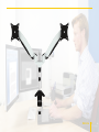
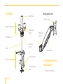
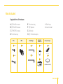
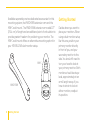
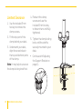
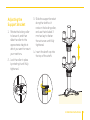
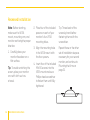
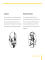
MD-BSL15W / SPRING-LOADED
TWIN-ARM
MONITOR mount
For 15″–27″ (38.1–68.6 cm) LCD desktop computer
User Manual
Thank you for
choosing Gabor.
The Gabor MD-BSL15W mounts two 15″–27″ (38.1–68.6 cm) LCD computer monitors side
by side. It attaches to the edge of your desk via a built-in clamp, freeing up valuable desk
space and enabling personalized monitor placement for improved safety and comfort over
conventional monitor stands. The MD-BSL15W’s arms incorporate an internal mechanical
spring system, which is safer than the gas springs found in similar products. These springloaded arms function as a counterbalance to support your monitors in any position. Multiple
points of articulation provide a full range of motion, making it easy to adjust your monitors’
height, tilt, swivel, and roll.
2
Welcome
Welcome
3
Overview
Mounting Arm (x2)
Shaft cap
VESA mount
Support bracket
Mounting
pegs
Set screw
Shaft
Clamp
Locking
collar
Cable guides
Clamp screws
Clamp locking
knob
4
Overview
Mounting
socket
Tools Required For
Installation
•
Phillips screwdriver
Also Included
M4x12A(x8)
M4x12 (x8)
M4x30 (x8)
M4x30 (x8)
A (8) M4×12 screws
B (8) M4×30 screws
S=3mm (x1)
C (2) M6×25 screws
D 3 mm hex key
E 5 mm hex key
S=3mm (x1)
F (8) Spacers
S=5mm (x1)
G Cable clip
H (2) Protective caps
S=5mm (x1)
A
Supplied Parts & Hardware
M4
A
B
A
A x8
I Shaft cap
J User manual
M6 M4x12
Spacers/
(x8) Hex Keys
M4x30
(x8)
Protective Caps
Cable clip
13X5.5X16.5 (x8)
(x1)
M4x12
(x8)
M4x30
(x8)
B
D x1
F x8
13X5.5X16.5
(x1)
H x2
A C x2 (x8)
S=3mm (x1)
S=5mm (x1)
M4x12 (x8)
M4x30
(x8)
M6x25
(x2)
E x1
I x1
(x1)
S=3mm (x1)
S=5mm (x2)
(x2)
M6x25 (x2)
B x8
G x1
S=3mm (x1)
S=5mm (x1)
13X5.5X16.5 (x8)
B
B
(Installed in shaft)
(x1)
13X5.5X16.5 (x8)
M6x25 (x2)
(x1)
(x2)
Overview
5
Product Specifications
Max. 28.7” (73 cm)
• Monitor display size:
15″—27″ (38.1–68.6 cm)
• VESA standards: 75×75, 100 × 100
• Tilt: -90°/+85°
• Swivel: 180°
• Installation: Clamp fits desk edges up to
2.6″ (6.5 cm) thick
• Arm width (extended): 28.7″ (73 cm)
• Arm pivot: 180°
• Arm height adjustment
Angle: ±45°
Range: 0″–13.8″ (0–35 cm)
• Shaft height: 12.2″ (31 cm)
• Weight: 8.25 lb. (3.7 kg)
6
Specifications
360°
180° 180°
85°
85°
180°
180°
+/-45°
12.2” (31c m)
• Roll: 360°
360°
+/-45°
0-13.8” (0-35 cm)
• Maximum load capacity (per arm): 17 lb. (7.8 kg)
90°
90°
Safety Warnings
1 Please read and follow these instructions
and keep this manual in a safe place.
2 Clean this product with only a soft, dry cloth.
3 Keep this product away from children.
4 Make sure everything is secure before
proceeding.
5 Make sure that this product is intact and
that there are no missing parts.
7 Do not exceed the maximum load capacity.
8 Do not install this product on an unsteady
structure or one that is prone to vibration,
has a chance of being impacted, or is
susceptible to other movements. Reinforce
the structure as necessary before installing
this product.
9 Mounting surfaces should be sturdy and flat.
Do not install this product on a weak, uneven
surface.
10 All photos are for illustrative purposes only.
6 To avoid damage to this product, be careful
not to overtighten or improperly thread any
of the threaded fittings.
Safety Warnings
7
Available separately are two dedicated accessories for this
mounting system, the MWD-E8W extension arm and the
MW-C wall mount. The MWD-E8W extension arm adds 10″
(25.4 cm) of length and an additional point of articulation to
provide greater freedom for positioning your monitor. The
MW-C wall mount offers an alternative mounting option for
your MD-BSL15W dual-monitor setup.
MW-C
MWD-E8W
8
Getting Started
Getting Started
Decide where you want to
place your monitors. When
using a dual-monitor setup
like this one, position your
primary monitor directly
in front of you, and your
secondary monitor to the
side. You shouldn’t need to
turn your head to look at
your primary monitor. Both
monitors should be at eye
level, approximately at an
arm’s length away. If you
have to strain to look at
either monitor, readjust its position.
Attaching the Shaft
• The MD-BSL15W easily
attaches to most desk
edges up to 2.6″ (6.5 cm)
thick, even if your desk
is nearly flush against a
wall. Before attaching
the shaft to your desk,
determine whether
you have enough room
to fit the entire clamp
behind your desk. If you
have enough clearance
to attach the clamp
without removing the
bottom part of it, skip to
Clearance on this page.
• If your desk is close to
a wall or you don’t have
enough clearance to fit
the entire clamp behind
your desk, you can
remove the bottom part
of the clamp. If this is
the case, skip to Limited
Clearance on page 10.
2. Fit the clamp over the
edge of your desk, and
tighten the clamp locking
knob until the shaft is
securely mounted to your desk.
• Continue with Adjusting
the Support Bracket on
page 11.
Clearance
1. Loosen the clamp locking
knob until you can fit the
clamp over the edge of
your desk.
Installation Instructions
9
Limited Clearance
1. Use the included 5 mm
hex key to remove the
clamp screws.
2. Fit the top part of the
clamp behind your desk.
3. Underneath your desk,
align the screw holes in
the top and bottom parts
of the clamp.
Note: It may help to unscrew
the clamp locking knob first.
10
Installation Instructions
4. Reinsert the clamp
screws and use the
included 5 mm hex key
to fasten them until fully
tightened.
5. Tighten the clamp locking
knob until the shaft is
securely mounted to your
desk.
• Continue with Adjusting
the Support Bracket on
page 11 .
Adjusting the
Support Bracket
1. Rotate the locking collar
to loosen it, and then
slide the collar to the
approximate height at
which you want to mount
your monitors.
2. Lock the collar in place
by rotating it until fully
tightened.
3. Slide the support bracket
along the shaft so it
rests on the locking collar,
and use the included 3
mm hex key to fasten
the set screw until fully
tightened.
4. Insert the shaft cap into
the top of the shaft.
Installation Instructions
11
Attaching Your Monitor to the VESA Mounts:
Before attaching your monitor to the VESA mount, you may need to detach your monitor’s
built-in stand. For information on how to do this, consult your monitor’s user manual.
Depending on how the back of your monitor is configured, you can use one of two methods to
install the VESA mount onto your monitor: flush or recessed. If your monitor’s VESA mounting
holes are flush with the rest of the monitor, use the Flush Installation instructions below. If
your monitor’s VESA mounting holes are in a recessed area of the monitor, use the Recessed
Installation instructions on page 14.
12
Installation Instructions
Flush Installation
Note: Before starting,
make sure the VESA mount,
mounting arm, and monitor
are facing the proper
direction.
2. Align the mounting
holes in the VESA mount
with the corresponding
mounting holes in your monitor.
1. Carefully place your
monitor facedown on a
flat surface.
3. Insert four of the M4×12
screws (the smallest
of the included screws)
into the VESA mount
and use a Phillips-head
screwdriver to fasten
them until fully tightened.
Tip: To avoid scratching the
screen, place your monitor
on a soft cloth such as a towel.
Repeat these or the other
set of installation steps as
necessary for your second
monitor and continue to
Mounting the Arms on page 15.
Installation Instructions
13
Recessed Installation
Note: Before starting,
make sure the VESA
mount, mounting arm, and
monitor are facing the proper
direction.
1. Carefully place your
monitor facedown on a
flat surface.
Tip: To avoid scratching the
screen, place your monitor
on a soft cloth such as
a towel.
14
Installation Instructions
2. Place four of the included
spacers on each of your
monitor’s four VESA
mounting holes.
Tip: Thread each of the
screws by hand before
fastening them with the
screwdriver.
3. Align the mounting holes
in the VESA mount with
the four spacers.
Repeat these or the other
set of installation steps as
necessary for your second
monitor, and continue to
Mounting the Arms on page 15.
4. Insert four of the included
M4×30 screws into the
VESA mount and use a
Phillips-head screwdriver
to fasten them until fully
tightened
Mounting the Arms
1. Lift the arm/monitor
assembly and mount it
onto one of the mounting
pegs on the aluminum
bracket.
3. Thread one of the included
protective caps onto the
screw as much as possible,
and then push the cap into
the socket.
2. Insert one of the included
M6×25 screws through the
bottom of the mounting
arm socket, and hold
the screw in place so it
protrudes from the screw
hole.
4. Use a short Phillips-head
screwdriver to fasten the
screw until fully tightened.
5. Insert your monitor cable
M6x25
into the cable
guides on the
underside of the mounting
B
arm.
Repeat these steps for the
other monitor/arm assembly,
and use the included cable
clip to secure your monitor
cables to the shaft.
Installation Instructions
15
Adjusting Tension and Articulation
Note: To avoid damage, make
sure to hold your monitor
steady when making any
adjustments.
Arm Tension
Important! The arm tension
is preset for lighter monitors.
To avoid damage, do not
continue to loosen the screw
if it’s already loose.
8
90°
360°
180°
+/-45°
16
0-13.8” (0-35 cm)
85°
Installation Instructions
To prevent your monitors
from drooping, you can adjust
the tension of the mechanical
spring in the mounting arms.
Use the included 5 mm hex
key to adjust tension. Rotate
clockwise to increase tension
for heavier monitors, and
counterclockwise to reduce
tension for lighter monitors.
S
Arm Swivel
Monitor Tilt and Swivel
You can adjust the arms’ (horizontal) swivel
action via the set screws on the rear of the
mounting sockets. Position the arms as
desired and use the included 3 mm hex key to
fasten the set screws until fully tightened.
You can adjust the (vertical) tilt and
(horizontal) swivel action of your monitors
for optimal viewing comfort. Position your
monitors as desired and use the 5 mm
hex key to fasten the set screws until fully
tightened.
Installation Instructions
S=3mm
S=5mm
A
17
Customer
Support
For more information or
to arrange service, visit
www.madebygabor.com
or call Customer Service
at 212-594-2353.
Product warranty is provided by
the Gradus Group.
www.gradusgroup.com
Gabor is a registered trademark
of the Gradus Group. © 2014 Gradus Group LLC. All Rights Reserved.
18
Customer Support / Warranty
ONE-YEAR LIMITED WARRANTY:
This GABOR product is warranted to the original purchaser to be free from defects in
materials and workmanship under normal consumer use for a period of one (1) year
from the original purchase date or thirty (30) days after replacement, whichever
occurs later. The warranty provider’s responsibility with respect to this limited
warranty shall be limited solely to repair or replacement, at the provider’s discretion,
of any product that fails during normal use of this product in its intended manner and
in its intended environment. Inoperability of the product or part(s) shall be determined
by the warranty provider. If the product has been discontinued, the warranty provider
reserves the right to replace it with a model of equivalent quality and function.
This warranty does not cover damage or defect caused by misuse, neglect,
accident, alteration, abuse, improper installation or maintenance. EXCEPT
AS PROVIDED HEREIN, THE WARRANTY PROVIDER MAKES NEITHER ANY
EXPRESS WARRANTIES NOR ANY IMPLIED WARRANTIES, INCLUDING BUT
NOT LIMITED TO ANY IMPLIED WARRANY OF MERCHANTABILITY OR FITNESS
FOR A PARTICULAR PURPOSE. This warranty provides you with specific legal
rights, and you may also have additional rights that vary from state to state.
To obtain warranty coverage, contact the Gabor Customer Service Department
to obtain a return merchandise authorization (“RMA”) number, and return the
defective product to Gabor along with the RMA number and proof of purchase.
Shipment of the defective product is at the purchaser’s own risk and expense.
Customer Support / Warranty
19
www.madebygabor.com