1
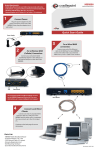
Mobile-Ready Office
User Guide
Installation, Configuration, and Management
MRO User Guide
Preface
Copyright
Copyright © 2015 Feeney Wireless LLC, a Novatel Wireless company. All rights reserved.
This document may not be copied in part or otherwise reproduced without prior written consent from Feeney
Wireless except where specifically permitted under US and International copyright law.
Disclaimer
The information in this document is subject to change without notice. Feeney Wireless (“FW”) assumes no
responsibility for inaccuracies or omissions and specifically disclaims any liabilities, losses, or risks, personal or
otherwise, incurred as a consequence, directly or indirectly, of the use or application of any of the contents of this
document. For the latest documentation, contact your local supplier or visit us online at www.feeneywireless.com.
This publication may contain examples of screen captures and reports used in daily operations. Examples may
include fictitious names or individuals and companies. Any similarity to names and addresses of actual businesses or
persons is entirely coincidental.
Trademarks and Patents
Feeney Wireless and the FW logo are trademarks of Feeney Wireless LLC. Skyus, Skyus 3G, Skyus 4G, Skyus Global,
Skyus-E, CIRA, CIRA X, CIRA X2, and Axiom are trademarks of Feeney Wireless LLC. VaraSight and the VaraSight logo
are trademarks of Feeney Wireless LLC.
Other trade names used in this document may be trademarks or registered trademarks of the manufacturers or
vendors of the respective products.
Intended Use
Use this product only for the purpose it was designed for; refer to the datasheet and user documentation. For the
latest product information, visit us online at www.feeneywireless.com.
Document Number: 25-52-004-01 (Revision A)
1
MRO User Guide
Contents
Overview .......................................................................................................................................................................................................................3
Intended Audience ..............................................................................................................................................................................................3
Scope.........................................................................................................................................................................................................................3
Specifications .........................................................................................................................................................................................................4
Antenna Specifications ......................................................................................................................................................................................5
Device Information ..............................................................................................................................................................................................6
Router Log-In Information...........................................................................................................................................................................6
Modem Log-In Information ........................................................................................................................................................................6
Installation Steps........................................................................................................................................................................................................6
Packing List .............................................................................................................................................................................................................6
Connecting the Source Power ........................................................................................................................................................................7
Antenna Mounting ..............................................................................................................................................................................................7
Mounting Cellular Antennas ......................................................................................................................................................................7
Mounting Wi-Fi Antennas ...........................................................................................................................................................................7
Antenna Connections .........................................................................................................................................................................................7
Connecting Cellular Antennas ...................................................................................................................................................................7
Connecting Wi-Fi Antennas ........................................................................................................................................................................8
Ethernet Connections .........................................................................................................................................................................................8
Verify Connection to the Internet ..................................................................................................................................................................9
Contacting Us ..............................................................................................................................................................................................................9
Online Library ..................................................................................................................................................................................................... 10
FCC Compliance ...................................................................................................................................................................................................... 10
2
MRO User Guide
Overview
The Feeney Wireless Mobile-Ready Office (MRO) is a multi-modem, multi-carrier Wi-Fi solution, allowing users to
harness some of the highest throughput available for field and mobile applications. The MRO is optimized to take
advantage of overlapping coverage footprints and provide redundancy in areas with poor signal. In areas with poor
signal strength the MRO uses failover logic to choose the modem with the best connection to continue
uninterrupted service, mitigating outages, congestion, interference, and coverage gaps.
Intended Audience
This document is intended for users responsible for the installation and initial set-up of the MRO and assumes the
installer possesses a basic working knowledge of computer networking, wireless routing, and network
administration.
For further information on using your device, please refer to the following relevant documentation:
•
•
•
•
Cradlepoint MBR1400 Configuration User Guide, available at http://www.cradlepoint.com/
AirLink GX440 User Guide, available at http://www.sierrawireless.com/
ALEOS Configuration User Guide, available at http://www.sierrawireless.com/
Skyus and Skyus-E Quick Start Guides, available at http://www.feeneywireless.com/
Scope
This User Manual focuses on the installation and configuration of the MRO system. For information necessary above
and beyond this level of operation, please consult the resources listed above or contact your FW representative.
In-Lid Instructions
Modem Bay –
4 bays accept GX440,
Skyus, Skyus-E, or
custom configurations
Cradlepoint 1400
Router
Power Button
Circuit Breaker
Figure 1: MRO Interior
3
MRO User Guide
Specifications
Hardware
Input Voltage
Power Consumption
Environmental
• 12V DC
• 120V AC
Kit includes DC vehicle cord and NEMA 5-15P (three-prong) AC cord.
• Router (Typical): 500mA at 12VDC, 1A peak per the supplied router
• Modem (Typical): 500mA at 12VDC, 1A peak per supplied modem
Varies based on system configuration.
• Operating Temperature: -0°C to 40°C (32°F to 104°F)
• Storage Temperature: -40°C to 85°C (-40°F to 185°F)
Housing
Pelican 1510 Carry On Case
Dimensions
13.81 x 9 x 22 inches
Weight
• MRO (without modems installed): Approx. 27 lbs.
• GX440 Modem (ea.): 12 oz.
Nominal additional weight with antenna array.
Mounting
Optional wall mounting plate and bracket
Data Interface
Wireless, Ethernet (LAN, WAN), USB, depending on configuration
Antenna Connections
See Antenna Specifications.
Cellular
Technologies
LTE with fallback to HSPA+, HSPA, UMTS, EDGE, GPRS, EVDO, 1xRTT (depending on
the modems used)
Carriers
Sprint, Verizon, AT&T, T-Mobile
Bands
See the specification sheet for the modem installed.
Standards/Approvals
FCC Part 15, Class B
4
MRO User Guide
Antenna Specifications
Due to the available customization options for the MRO, multiple antenna configurations are possible. To ensure
that your system is configured for optimal performance please contact your FW sales representative.
Wi-Fi Array
Reverse-polarity TNC
Cellular/GPS Array
TNC
Figure 2: Antenna Plate
Depending on the configuration, the MRO is typically shipped with one or more portable wireless “blade” antennas
with the characteristics shown in the following table.
Attribute
Value
Operating Frequencies
•
•
•
•
•
•
•
Polarization
Linear
Peak Gain
3 dBi
Dimensions
6.3 in. L x 0.36 in. W
Voltage Standing Wave Ratio (~:1)
2:5:1
824 – 894 MHz
880 – 960 MHz
1575 MHz
1710 – 1880 MHz
1850 – 1990 MHz
1920 – 2170 MHz
2400 – 2500 MHz
For Wi-Fi antenna specifications, see the Cradlepoint MBR1400 Configuration User Guide available at
http://www.cradlepoint.com/.
NOTE: Wi-Fi antenna connectors are Reverse Polarity TNC (RP-TNC). Avoid connecting a non-reverse polarity
connector to one of these ports to avoid damage to the connector center pin.
5
MRO User Guide
Device Information
The MRO router and modems are preconfigured for optimum performance in your unique deployment. Logging into
the devices is not typically required for normal operation of the MRO.
Router Log-In Information
Router information is located on the router label. To access the router administration pages, open a Web browser
and type in the router IP address “http://192.168.0.1” in the address bar. The Administrator Login page will appear.
Log in using the default administrator password found on the router label. The password is typically the last eight
digits of the router’s MAC address. See the Cradlepoint MBR1400 Configuration User Guide for more information.
Modem Log-In Information
Modem information is located on the MRO label. To log in to the modem administration page, use the URL, port
number, and login credentials provided on the label, as shown below.
Figure 3: MRO Label
Installation Steps
1.
2.
3.
4.
5.
6.
Inspect the package contents and compare against the packing list.
Connect power (AC or DC) from the power source to the MRO.
Connect cellular, GPS, and Wi-Fi antennas to the device.
Turn on the power switch.
Verify activation of the device.
Verify connection to the Internet.
Packing List
The MRO is a modular system that is shipped in a wide variety of configurations. After removing the unit from the
shipping container, inspect the packing list to ensure that your complete order has arrived. If any items are missing
or damaged, contact FW support.
6
MRO User Guide
Connecting the Source Power
The MRO is equipped with both an AC and DC power cord. Connect the appropriate cable for your power source to
the MRO and the power source. The connectors are keyed for proper orientation. Be sure that you mate the
connectors properly.
Antenna Mounting
Mounting Cellular Antennas
When using a cable to an antenna placed away from the modem, minimize the length of your cable. All gain from a
more advantageous antenna placement can be lost with a long cable to the MRO.
When mounting the GPS antenna, the less the cable is wrapped and bound together, the better it will perform. Place
the antenna where it has a good view of the sky (> 90° angle view).
Mounting Wi-Fi Antennas
Wi-Fi antennas should be installed in locations that allow for complete coverage of the desired connected area.
Some antennas are omnidirectional and can be placed in the center of the desired coverage area, whereas,
directional antennas should be placed in locations that direct the signal toward your desired coverage area. Refer to
the installation manual of your antenna or contact FW for further instruction.
Antenna Connections
Connecting Cellular Antennas
The cellular and GPS antennas for each modem connect to the ports shown below.
ANT 1
GPS
ANT 2
AUX
Figure 4: Modem Antenna Connections
When using a Multiple Input/Multiple Output (MIMO) cellular antenna, it can be attached to either the ANT 1 or ANT
2 connector. Connect GPS or auxiliary antennas to the designated connectors.
NOTE: The use of at least one modem for GPS purposes is recommended to allow for more effective remote
monitoring of possible cellular issues.
You can use one or two USB cellular modems for failover protection. Follow the connection pattern shown below
when using USB cellular modems.
7
MRO User Guide
Primary
Secondary
Figure 5: USB Failover Connections
Connecting Wi-Fi Antennas
When connecting Wi-Fi antennas to the MRO, start with WIFI 1 and progress to WIFI 2 and WIFI 3.
Figure 6: Wi-Fi Antenna Connections
Ethernet Connections
One WAN and four LAN RJ-45 connectors are provided on the side panel of the MRO case as shown below. These
connectors have been implemented according to the configuration you ordered.
Figure 7: WAN and LAN Connectors
8
MRO User Guide
Verify Connection to the Internet
After connecting power, antennas, and other connections, verify that you have a live connection to the internet. To
do this, follow the steps below.
1.
2.
3.
4.
Open a Windows Command Prompt (Start > All Programs > Accessories > Command Prompt).
In the Command Prompt Window, type: Ping 4.2.2.1. (This is a public DNS server.)
Press Enter.
Ensure you receive the following response, as seen in Figure 8.
NOTE: If you see “Request time out,” your device is not communicating over the Internet.
Figure 8: Verifying Internet Connection
Contacting Us
For help with installing, operating, maintaining, and troubleshooting this product, refer to this document and any
other documentation provided. If you still have questions, contact us during business hours: Monday through Friday,
excluding holidays, between 8 a.m. and 5 p.m. Pacific Time.
Contact Us
Support E-Mail
Telephone
Website
Mailing Address
[email protected]
(800) 683-4818
www.feeneywireless.com
P.O. Box 2549, Eugene, OR 97402
When contacting technical support, please have the following information on-hand:
1.
2.
3.
MRO serial number
Date that you received your device
Brief description of the problem
9
MRO User Guide
Online Library
For other documentation, see the document library at:
http://feeneywireless.com/documents
FCC Compliance
This equipment has been tested and found to comply with the limits for a Class B digital device, pursuant to part 15
of the FCC rules. These limits are designed to provide reasonable protection against harmful interference when the
equipment is operated in a residential environment. This equipment generates, uses, and can radiate radio
frequency energy and, if not installed and used in accordance with the instruction manual, may cause harmful
interference to radio communication. FW does not guarantee that interference will not occur in a particular
installation.
Operation is subject to the following conditions:
a.
b.
This device may not cause harmful interference.
This device must accept any interference received, including interference that may cause undesired
operation.
Changes or modifications not expressly approved by the party responsible for compliance could void the user’s
authority to operate the equipment.
If this equipment does cause harmful interference to radio or television reception, which can be determined by
tuning the equipment off and on, the user is encouraged to try and correct the interference by one or more of the
following measures:
a.
b.
c.
d.
Reorient or relocate the receiving antenna.
Increase the distance between the equipment and the receiver.
Connect the equipment to outlet on a circuit different from that to which the receiver is connected.
Consult the dealer or an experienced radio/TV technician for help.
Exposure to RF radiation - To comply with FCC RF exposure compliance requirements, for mobile configurations, a
separation distance of at least 20cm must be maintained between the antenna of this device and all persons. Do not
collocate or operate this device in conjunction with any other antenna or transmitter.
10