1
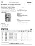
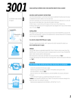
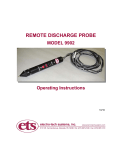
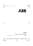
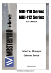
1
Power Protection and Conditioning
MCR Hardwired Series – Power Line Conditioning with Voltage Regulation
The MCR Hardwired Series provides excellent noise
filtering and surge suppression to protect connected
equipment from damage, degradation or misoperation.
Combined with the excellent voltage regulation inherent to
Sola/Hevi-Duty’s patented ferroresonant design, the MCR
can increase the actual Mean Time Before Failure (MTBF)
of protected equipment. The MCR is a perfect choice where
dirty power, caused by impulses, swell, sags, brownouts and
waveform distortion can lead to costly downtime because of
damaged equipment.
Features
• ±3% output voltage regulation
• Noise attenuation
- 120 dB common mode
- 60 dB transverse mode
• Surge suppression tested to ANSI/IEEE
C62.41 Class A & B Waveform:
- <10 V let through typical
• Acts as a step-up or step-down transformer
• Harmonic filtering
• Hardwired
• Galvanic isolation provides exceptional
circuit protection.
• 25 year typical MTBF
• No maintenance required
Applications
• Industrial automation and control equipment PLCs
• Machine tools
• Computer loads and electronic equipment
• Robotics
• Semiconductor fabrication equipment
Related Products
• On-line UPS (S4K Industrial)
• Surge Suppression
• Three Phase Power Conditioners
Selection Tables: Single Phase
Group 2 – MCR Series, 60 Hz Only
VA
Catalog Number
Voltage Input
Voltage Output
Height
(inch)
Width
(inch)
Depth
(inch)
Ship Weight
(lbs)
Design
Style
Elec
Conn
120
63-23-112-4
120, 208, 240, 480
120
9
4
5
15
1
D
250
63-23-125-4
120, 208, 240, 480
120
10
6
8
27
1
D
500
63-23-150-8
120, 208, 240, 480
120, 208, 240
13
9
7
37
1
E
750
63-23-175-8
120, 208, 240, 480
120, 208, 240
14
9
7
52
1
E
1000*
63-23-210-8
120, 208, 240, 480
120, 208, 240
17
9
7
62
1
E
1500*
63-23-215-8
120, 208, 240, 480
120, 208, 240
17
13
9
95
1
E
2000*
63-23-220-8
120, 208, 240, 480
120, 208, 240
18
13
9
109
1
E
3000*
63-23-230-8
120, 208, 240, 480
120, 208, 240
19
13
9
142
1
E
5000*
63-23-250-8
120, 208, 240, 480
120, 208, 240
28
13
9
222
1
E
7500**
63-28-275-8
208, 240, 480
120, 208, 240
27
26
9
362
2
F
10000**
63-28-310-8
208, 240, 480
120, 208, 240
28
26
9
446
2
F
15000**
63-28-315-8
208, 240, 480
120, 208, 240
28
38
10
710
3
F
* Canadian option: cULus certified units must be ordered by changing “-8” (UL only) to “-C8”.
** UL Listed Only. Use Group 3 for cULus.
28
Gross Automation (877) 268-3700 · www.solahevidutysales.com · [email protected]
Gross Automation (877) 268-3700 · www.solahevidutysales.com · [email protected]
1
Power Protection and Conditioning
Selection Tables: Single Phase
Group 3 – MCR Series, 60 Hz Only
VA
Catalog Number
Voltage Input
Voltage Output
Height
(inch)
Width
(inch)
Depth
(inch)
Ship weight
(lbs)
Design
Style
Elec
Conn
500
63-31-150-8
600
120, 208, 240
13
9
7
38
1
B
1000
63-32-210-8
600
120, 208, 240
17
9
7
62
1
B
2000
63-32-220-8
600
120, 208, 240
18
13
10
109
1
B
3000
63-32-230-8
600
120, 208, 240
19
13
10
142
1
B
5000
63-29-250-8
208, 240, 480, 600
120, 208, 240
28
13
10
221
1
A
7500
63-29-275-8
208, 240, 480, 600
120, 208, 240
27
25
10
360
2
A
10000
63-29-310-8
208, 240, 480, 600
120, 208, 240
28
25
10
441
2
A
15000
63-29-315-8
208, 240, 480, 600
120, 208, 240
28
38
10
706
3
A
Group 4 – MCR Series, 50 Hz Only (±5% output voltage regulation)
VA
Catalog Number
120
Voltage Input
Voltage Output
Height
(inch)
Width
(inch)
Depth
(inch)
Ship weight
(lbs)
Design
Style
Elec
Conn
63-23-612-8
110, 120, 220, 240, 380, 415
110, 120, 220, 240
9
6
8
24
1
C
250
63-23-625-8
110, 120, 220, 240, 380, 415
110, 120, 220, 240
11
6
8
27
1
C
500
63-23-650-8
110, 120, 220, 240, 380, 415
110, 120, 220, 240
13
9
7
40
1
C
1000
63-23-710-8
110, 120, 220, 240, 380, 415
110, 120, 220, 240
18
9
7
64
1
C
2000
63-23-720-8
110, 120, 220, 240, 380, 415
110, 120, 220, 240
18
13
10
113
1
C
3000
63-23-730-8
110, 120, 220, 240, 380, 415
110, 120, 220, 240
27
13
10
162
1
C
5000
63-23-750-8
110, 120, 220, 240, 380, 415
110, 120, 220, 240
30
13
10
266
1
C
7500
63-28-775-8
220, 240, 380, 415
110, 120, 220, 240
28
26
10
393
2
C1
10000
63-28-810-8
220, 240, 380, 415
110, 120, 220, 240
30
26
10
490
2
C2
15000
63-28-815-8
220, 240, 380, 415
110, 120, 220, 240
30
38
10
776
3
C2
Specifications
Parameter
Condition
Value
Input
Voltage
Current
1
Frequency
Continuous at full load (lower input voltage possible at lighter load)
+10% to -20% of nominal
For temporary surge or sags
+20% to -35% of nominal
at Full Load & 80% of nominal input voltage
Iin ≅ (VA/.89)/(Vin x 80%)
See Operating Characteristics section for details.
50 Hz or 60 Hz depending on model
Output
Line Regulation
Overload Protection
Output Harmonic Distortion
Noise Attenuation
Vin >80% and <110% of nominal
± 5% for 50 Hz units, ± 3% for 60 Hz units
At Nominal Input Voltage
Current limited at 1.65 times rated current
At full load within input range
3% total RMS content
-Common Mode
-Transverse Mode
120 dB
60 dB
General
At Full Load
Up to 92%
Storage Temperature
Humidity <95% non-condensing
-20° to +85°C
Operating Temperature
Humidity <95% non-condensing
-20° to 50°C
Full Resistive Noise
35 dBA to 65 dBA
60 Hz Models
UL1012, CSA evaluated by UL
50 Hz Models
CE (EMC & LVD)
See General Information section for details
10 + 2 Years
Efficiency
Audible Noise
Approvals
Warranty
Notes:
1 - Consult user manual for fuse sizing.
Gross Automation (877) 268-3700 · www.solahevidutysales.com · [email protected]
Gross Automation (877) 268-3700 · www.solahevidutysales.com · [email protected]
29
1
Power Protection and Conditioning
Electrical Connections
A
Primary Voltage
Interconnect
B
Connect Lines To
208
H1 to H4
H2 to H5
H1 & H5
240
H1 to H4
H3 to H6
H1 & H6
Primary
Voltage
480
H3 to H4
H1 & H6
600
600
H3 to H4
H1 & H7
Secondary Voltage
Interconnect
Connect Lines To
Secondary
Voltage
120
X1 & X2 or X3 & X2
208
X4 & X5
240
X1 & X3
Interconnect
H1 & H2
Interconnect
X1 & X2 or X3 & X2
208
X4 & X5
240
220-240
H1 to H3
H2 to H5
380-415
Connect Lines To
H1 & H5
H2 to H3
Secondary Voltage
Interconnect
Connect Lines To
110-120
H1 to H3
H2 to H4
H1 & H4
220-240
H2 to H3
H1 & H4
380-415
H2 to H3
H1 & H5
Secondary Voltage
Interconnect
Connect Lines To
110
X1 & X2 or X3 & X2
120
X4 & X2 or X5 & X2
220
X1 & X3
240
X4 & X5
MCR 60 Hz 500–3000 VA
MCR 50 Hz 120–5000 VA
C2
D
Primary Voltage
Interconnect
Connect Lines To
Primary Voltage
220-240
H2 to H3
H1 & H4
120
H1 & H2
380-415
H2 to H3
H1 & H5
208
H1 & H3
Secondary Voltage
Interconnect
Connect Lines To
240
H1 & H4
110
X1 & X2 or X3 & X2
480
H1 & H5
120
X4 & X2 or X5 & X2
Secondary Voltage
220
X1 & X3
120
240
X4 & X5
Interconnect
Connect Lines To
H1 & H4
Interconnect
Connect Lines To
110
X1 & X2 or X2 & X3
120
X4 & X2 or X5 & X2
220
Interconnect
Connect Lines To
X1 & X2
X1 & X3
240
X4 & X5
MCR 50 Hz 7500 VA
30
Primary Voltage
X1 & X3
C1
Interconnect
Connect Lines To
120
MCR 60 Hz 5000–15000 VA
Primary Voltage
Connect Lines To
C
MCR 60 Hz 120–250 VA
MCR 50 Hz 10000–15000 VA
Gross Automation (877) 268-3700 · www.solahevidutysales.com · [email protected]
Gross Automation (877) 268-3700 · www.solahevidutysales.com · [email protected]
1
Power Protection and Conditioning
Electrical Connections
E
Primary Voltage
Interconnect
Connect Lines To
H1 & H2
Primary Voltage
208
H1 & H3
208
240
H1 & H4
240
480
H1 & H5
480
120
G
F
Interconnect
Connect Lines To
Primary Voltage
Interconnect
Connect Lines To
120
H1 to H3 H5 to H7
H2 to H4 H6 to H8
H1 & H2
240
H2 to H3 H6 to H7
H1 to H5 H4 to H8
H1 & H4
480
H2 to H3 H4 to H5
H6 to H7
H1 & H8
Interconnect
Connect Lines To
H2 & H3
H2 & H4
H1 & H4
Connect Lines To
Secondary Voltage
120
X1 & X2 or X3 & X2
120
X1 & X2 or X3 & X2
208
X4 & X5
208
X4 & X5
Secondary Voltage
X1 & X3
120
Secondary Voltage
Interconnect
240
X1 & X3
Interconnect
Connect Lines To
240
X1 & X2
MCR 60 Hz 500–5000 VA
MCR 60 Hz 7500, 10000 and 15000 VA
H
Series-Multiple Primary
with Tap for two input voltages
CVS 60 Hz 250 VA only
J
Open MCR/CVS terminal
Primary Voltage
Interconnect
Connect Lines To
120
H1 to H3 to H6 to H8
H2 to H5 to H7 to H10
H1 & H2
30 & 60 VA
Primary Voltage
120 VA
Primary Voltage
7500 VA
Primary Voltage
Interconnect
Connect
Lines To
120
N/A
N/A
Note: H3 & H4
are not used
H1 & H2
240
H1 to H3
H2 to H4
H1 & H4
208
H2 to H3
H1 to H6
H7 to H8
H4 to H9
H1 & H4
240
H2 to H3 H7 to H8
H1 to H6 H5 to H10
H1 & H5
N/A
240
480
H2 to H3
H1 & H4
480
H2 to H3 H5 to H6
H7 to H8
H1 & H10
30 & 60 VA
Secondary Voltage
120 VA
Secondary Voltage
7500 VA
Secondary Voltage
Interconnect
Connect
Lines To
Secondary Voltage
Interconnect
N/A
120
Connect Lines To
120
120
N/A
X1 & X2
120
X1 & X2 or X3 & X2
N/A
N/A
120
X1 & X2 or
H3 & X2
240
X1 & X3
N/A
N/A
240
X1 & X3
CVS 60 Hz 500–5000 VA
Note:
Secondaries are
not grounded.
Ground X2 per
Code.
CVS 60 Hz 30–120 VA & 7500 VA
Gross Automation (877) 268-3700 · www.solahevidutysales.com · [email protected]
Gross Automation (877) 268-3700 · www.solahevidutysales.com · [email protected]
31
1
Power Protection and Conditioning
Model Comparison
Description
VA Ratings
Hardwired CVS
Hardwired MCR
Portable MCR
30 to 7500 VA
120 to 15000 VA
70 to 3000 VA
+10/-20% of nominal
Input Voltage Range
Voltage Regulation
±1% for an input line variation of +10/-20%.
No loss of output for line loss of 3 msec.
±3% for an input line variation of +10/-20% (50 Hz hardwired units ±5%.)
No loss of output for complete line loss of 3 msec.
Limits output current to 1.65 x rated current at nominal input.
Overload
Output Harmonic
Distortion
3% total RMS content at full load.
40 dB common and normal code.
120 dB common mode and 60 dB normal mode.
Up to 6000 Volt surges are suppressed to a
let through of less than 1% per ANSI/IEEE
C62.41 Class A & B waveforms.
ANSI/IEEE C62.41 Class A & B 6000 waveforms are
suppressed to a let-through of less than 0.2%.
Noise Isolation
Surge Suppression
Efficiency
Operating
Temperature
Up to 92% at full load
Up to 90% at full load
-20oC to 50oC
-20oC to 40oC
Audible Noise
32 dB to 65 dB
35 dB to 65 dB
34 dB to 49 dB
Conformance
Listed to UL 1012. CSA Certified
UL Listed and CSA Certified.50 Hz
models in compliance with Low Voltage
Directive Specification EN60950.
Listed to UL 1012. CSA Certified on
all models except 3000 VA.
Warranty
10 + 2 years
Note: All values are typical and may vary based on VA ratings of actual units.
BTU Output Chart for CVS and MCR Series
VA Ratings
120
250
500
750
1000
1500
2000
3000
5000
7500
10000
15000
Total BTU’s
136
225
280
444
519
686
1229
1331
2117
2407
3209
4813
Note: Ratings are for a 40oC ambient temperature.
34
Gross Automation (877) 268-3700 · www.solahevidutysales.com · [email protected]
Gross Automation (877) 268-3700 · www.solahevidutysales.com · [email protected]
1
Power Protection and Conditioning
Operating Characteristics of the CVS & MCR Series
Regulation
Sola/Hevi-Duty’s CVS power conditioners will hold output
voltages to ±1.0% or less with input variations as great as
±15% (115V ±15% or 120 V +10%/-20%). Units operated at
less than rated load will maintain approximately ±1% regulation over a wider input line voltage variation. Output meets
NEMA voltage specifications even when input voltage drops
to 65% of nominal. The output versus input voltage relationship for a typical CVS is show in Figure A.
CVS
Conditioner
Rating - VA
Increase in Output
Voltage due to
Load Removal
30
3%
60 & 120
2%
250 & over
1%
Input Characteristics
Sola/Hevi-Duty power conditioners include a resonant
circuit that is energized whether or not it is serving load. The
input current at no load or light load may run 50% or more
of the full primary current. As a result, the temperature of the
unit may rise to substantially full-load level, even at light or no
load. Input power factor will average 90-100% at full load,
but may drop to about 75% at half load and 25% at no load.
In any case, the current is always leading. The input no load
watts are about 12.5% of the VA rating.
Figure A: Load Variation
Note: MCR line regulations: ±3% for 60 Hz; ±5% for 50 Hz.
The typical performances shown in Figure B indicate that
most of the residual changes take place near the lower
(95 V) and upper (130 V) ends of the input range. It is
possible to improve output regulation if line variations remain
within a restricted range near the center of the nameplate
range (for example, 100-120 V).
Frequency
Output voltage varies linearly with a change of frequency of
the input voltage. This change is about 1.5% of the
output voltage for each 1% change in input frequency and in
the same direction as the frequency change.
Power Factor
Sola/Hevi-Duty power conditioners regulate any power factor
load. Output voltage is a function of load current and load
power factor (see Figure C). If lower voltage under lagging
power factor is objectionable, correction may be made with
capacitors at the load. “Median” value of output voltage will
vary from the nameplate rating if the load has a power
factor other than that for which the transformer was
designed. Load regulation will also be relatively greater as
the inductive load power factor is decreased (see Figure C).
However, the resulting median values of output voltage will
be regulated against supply line changes at any reasonable
load or load power factor.
Figure B: Line Regulation
Normally, the output voltage will rise as the load is
decreased. Typical percentages for changes in resistive
load from full to zero load as shown below.
Except as noted, all characteristics of Sola/Hevi-Duty’s CVS products also
apply to the MCR series.
Gross Automation (877) 268-3700 · www.solahevidutysales.com · [email protected]
Gross Automation (877) 268-3700 · www.solahevidutysales.com · [email protected]
35
1
Power Protection and Conditioning
Operating Characteristics of the CVS & MCR Series
Figure C: Power Factor
Efficiency
The copper magnet wire and lamination material used in
Sola/Hevi-Duty ferroresonant products are selected to
achieve efficiencies of 90% or higher. Whether or not an
external load is being served, current will be drawn from the
line whenever the primary is energized, since the capacitor
remains connected in the circuit.
Overload and Short Circuits
When the load is increased beyond the regulator’s rated
value, a point is reached where the output voltage suddenly
collapses and will not regain its normal value until the load is
partially released. Under direct short circuit, the load current
is limited to approximately 150-200% of the rated full load
value and the input watts to less than 10% of normal.
A constant voltage regulator will protect both itself and its
load against damage from excessive fault currents. Fusing
of load currents may not be necessary. The actual value of
short-circuit current varies with the specific design and
rating. Units may be operated indefinitely at short-circuit.
This characteristic protects the unit itself as well as the load
and load circuit being served. Typical overload
performance is shown in Figure D.
36
Figure D: Overload Performance
Motor Loads
Because of the fast response time of the Sola circuit, any
current-limiting characteristic must be taken into account
for transient overloads such as motor starting and solenoid
operation. In general, the Sola constant voltage regulator
must have a capacity nearly equal to the maximum demand
made on it, even for an instant. To determine the power
rating of the regulator, peak motor-starting current or
solenoid inrush current should be measured or power factor
correcting capacitors should be used to reduce the starting
VA of the load.
Response Time
An important advantage of Sola’s ferroresonant transformer
is its fast response time compared with other types of AC
regulators. Transient changes in supply voltage are usually
corrected within 1-1/2 cycles or less; the output voltage
will not fluctuate more than a few percent, even during this
interval.
Gross Automation (877) 268-3700 · www.solahevidutysales.com · [email protected]
Gross Automation (877) 268-3700 · www.solahevidutysales.com · [email protected]
Power Protection and Conditioning
1
Operating Characteristics of the CVS & MCR Series
Temperature
Sola’s ferroresonant power conditioners are very stable
with respect to temperature. The change in output voltage
is only 0.025%/°C. Units are factory adjusted to +2%/-0%
of nominal, with full load and nominal input voltage. This
adjustment to the high side of nominal is to compensate for
the natural temperature drift of about 1% that takes place
during initial turn-on or warm-up. When the unit warms up to
operating temperature, the voltage typically falls about 1%.
At a stable operating temperature, the output voltage will
change slightly with varying ambient temperatures. This shift
is equal to approximately 1% for each 40°C of temperature
change. The normal maximum temperature rise of a Sola
power conditioner may fall anywhere in the range of 40°C
to 110°C depending on the type and rating. The nominal
design ambient range is between -20°C and +50°C (-20°C
to +40°C for 70 - 1000 VA, 60 Hz portable models).
External Magnetic Field
In almost all applications, this effect may be disregarded.
The exclusive Sola/Hevi-Duty “wide outside leg” construction
(U.S. Patent 2,806,199) reduces stray magnetic fields to a
practical minimum. On critical applications, care should be
taken in orientation of the core with respect to critical circuits
to minimize the effect of the field.
Phase Shift
The phase difference which exists between input and
output voltages is in the range of 120 degrees to 140 degrees at full load. This phase difference varies with the magnitude and power factor of the load, and to a lesser extent,
with changes in line voltage and load power factor.
Transient Protection
Ferroresonant power conditioners protect input transients
(caused by lightning and load switching) from damaging the
sensitive electronic load. A typical surge protective device
(SPD) tries to ‘clamp’ a transient by diverting it to ground.
A ferroresonant power conditioner “blocks” the transient.
This ‘blocking’ action is achieved by total physical separation
from input (primary) to output (secondary). Because of
this difference in operation, it is difficult to apply the same
specifications to a ferroresonant power conditioner. Some
parallels can be made however.
One, is that under load, the let-through voltage of a
ferroresonant power conditioner (SPD refer to "clamping
voltage”) is less than 10 V above the point where the sine
wave would normally be at any given time. The ferroresonant power conditioner is an ‘active tracking’ suppressor
with several advantages. The Ferro power conditioner will
not shunt the transient to the ground line as SPD devices
typically do. Shunting the transient to ground can cause the
disturbance to be transmitted to other sensitive loads within
a facility. This can pose serious problems with electronic or
microprocessor-based equipment, especially if there is poor
grounding within a facility. Other advantages provided by ferroresonant power conditioners include noise filtering, filtering
of harmonic distortion and protection against voltage fluctuations such as sags or swells. These features are not provided
by standard surge suppression devices but are often
misrepresented or misused by SPD manufacturers trying to
market their product as a “Do All” power quality device.
Gross Automation (877) 268-3700 · www.solahevidutysales.com · [email protected]
Gross Automation (877) 268-3700 · www.solahevidutysales.com · [email protected]
37