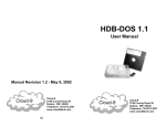
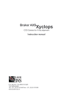
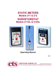
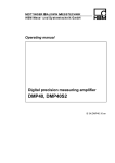
1
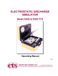
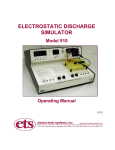
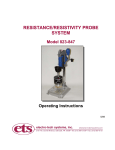
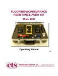
REMOTE DISCHARGE PROBE
MODEL 9902
Operating Instructions
10/10
IMPORTANT
SAFETY INSTRUCTIONS
(Equipment containing HV)
The equipment described in this Manual is designed and manufactured to operate
within defined design limits. Any misuse may result in electric shock or fire. To prevent
the equipment from being damaged, the following rules should be observed for
installation, use and maintenance. Read the following safety instructions before
operating the instrument. Retain these instructions in a safe place for future reference.
POWER
POWER CORD: Use only the power cord specified for this equipment and certified
for the country of use. If the power (mains) plug is replaced, follow the wiring
connections specified for the country of use. When installing or removing the power
plug hold the plug, not the cord.
The power cord provided is equipped with a 3-prong grounded plug (a plug with a
third grounding pin). This is both a safety feature to avoid electrical shock and a
requirement for correct equipment operation. If the outlet to be used does not
accommodate the 3-prong plug, either change the outlet or use a grounding adapter.
FUSES: Replace fuses only with those having the required current rating, voltage
and specified type such as normal blow, time delay, etc. DO NOT use makeshift
fuses or short the fuse holder. This could cause a shock or fire hazard or severely
damage the instrument.
POWER LINE VOLTAGE (MAINS): If the line (mains) voltage is changed or isolated
by an autotransformer the common terminal must be connected to the ground
(earth) terminal of the power source.
OPERATION
CAUTION
Equipment designed to simulate a high voltage electrostatic discharge such as the
Series 900 ESD Simulators and the Model 4046 Static Decay Meter utilize voltages
up to 30kV. The basic nature of an ESD event will result in electromagnetic radiation
in addition to the high level, short duration current pulse. Therefore, personnel with
a heart pacemaker must not operate the instrument or be in the vicinity while it
is being used.
DO NOT OPERATE WITH COVERS OR PANELS REMOVED. Voltages inside the
equipment can be as high as 30kV. In addition, equipment may contain
capacitors up to 200pF charged to 2kV. Capacitors can retain a charge even if
the equipment is turned off.
DO NOT OPERATE WITH SUSPECTED EQUIPMENT FAILURES. If any odor or
smoke becomes apparent turn off the equipment and unplug it immediately. Failure
1
to do so may result in electrical shock, fire or permanent damage to the equipment.
Contact the factory for further instructions.
DO NOT OPERATE IN WET/DAMP CONDITIONS: If water or other liquid
penetrates the equipment, unplug the power cord and contact the factory for further
instructions. Continuous use in this case may result in electrical shock, fire or
permanent damage to the equipment.
DO NOT OPERATE IN HIGH HUMIDITY: Operating the equipment in high humidity
conditions will cause deteriation in performance, system failure, or present a shock
or fire hazard. Contact the factory for further instructions.
DO NOT OPERATE IN AREAS WITH HEAVY DUST: Operating the equipment in
high dust conditions will cause deteriation in performance, system failure, or present
a shock or fire hazard. Contact the factory for further instructions.
DO NOT OPERATE IN AN EXPLOSIVE ATMOSPHERE: Operating the equipment
in the presence of flammable gases or fumes constitutes a definite safety hazard.
For equipment designed to operate in such environments the proper safety devices
must be used such as dry air or inert gas purge, intrinsic safe barriers and/or
explosion-proof enclosures.
DONOT USE IN ANY MANNER NOT SPECIFIED OR APPROVED BY THE
MANUFACTURER: Unapproved use may result in damage to the equipment or
present an electrical shock or fire hazard.
MAINTENANCE and SERVICE
CLEANING: Keep surfaces clean and free from dust or other contaminants.
Such contaminants can have an adverse affect on system performance or
result in electrical shock or fire. To clean use a damp cloth. Let dry before use.
Do not use detergent, alcohol or antistatic cleaner as these products may have an
adverse affect on system performance.
SERVICE: Do not attempt to repair or service the instrument yourself unless
instructed by the factory to do so. Opening or removing the covers may expose
you to high voltages, charged capacitors, electric shock and other hazards. If
service or repair is required, contact the factory.
2
1.0 INTRODUCTION
The ETS Model 910 Electrostatic Discharge Simulator evaluates the ESD
suceptability of electronic devices using either the Human Body (HBM) or the
Machine (MM) Models. The Human Body Model utilizes a 100pf capacitance
discharged through a 1500 Ohm resistor up to ±8kV over 2 ranges. The LO
Range generates discharge pulses from approximately 5 Volts to 2000 Volts with
a resolution of 1 Volt. The HI Range generates discharge pulses from
approximately 30 Volts to 8000 Volts with a resolution of 10 Volts.
The Machine Model uses a 200pf capacitance discharged through 0 Ohms and
operates only in the LO Range.
The Charged Device Model (CDM) is when the device itself is slowly charged
and then discharged to ground is available as an option.
All discharges functions are performed using the 6” (154mm) discharge cables
that plug into the Simulator front panel.
There are certain applications where it is desired to apply an ESD pulse to
devices that either may not conveniently fit onto one of the Model 910 discharge
modules or added to an automatic pick and place test set up.
The ETS Model 9902 is a remote probe that operates only in the LO Range (up
to 2000V) for all discharge Models. The Model 910 must be modified to provide
the necessary signals to operate the Probe. The Probe shown in Figure 1.0-1
can be used as a handheld device or with the addition of remote cables, be
attached to an automatic test system.
Figure 1.0-1: Model 9902 Remote Discharge Probe
3
2.0 DESCRIPTION
The Model 9902 is housed in an aluminum tube measuring 8.0” (203mm) long by
1.25” (32) diameter. It includes a removable discharge head with a replaceable
spring-loaded pointed discharge tip and a set of 12” long discharge cables that
are terminated with standard 0.161” (4mm) banana plugs plus a pair of springloaded adapters with pointed spring-loaded discharge tips for attachment to a
pick and place or remote test set up. Red and Black 0.5” (6mm) jumpers are
provided to select the HBM, MM and CDM functions. A spare set is also
included. The Remote Probe is connected to the Model 910 via an 8.5’ (2.5m)
cable assembly that consists of high voltage, ground and control signal leads.
The supplied assembly is shown in Figure 2.0-1.
Figure 2.0-1: Model 9902 plus accessories
Each discharge function requires its own unique set of cables in order to achieve
the required waveform. This will be covered in detail in Section 3.0 SET UP.
A manual remote discharge button is also included in the Remote Probe
assembly.
When the discharge head is used the position of the white dot indicates which
function the discharge tip is connected.
4
3.0 SET UP
The Model 9902 MUST ALWAYS BE HELD OR MOUNTED VERTICALLY. The
assembly contains mercury-wetted relays that operate only in the vertical mode.
However, when holding the Probe it may be offset by as much as 30 degrees
from the vertical and still operate satisfactorily.
3.1 Connection to Model 910
The Model 910 MUST BE MODIFIED at the factory in order for the Model
9902 Remote Discharge Probe to operate. Figure 3.0-2 shows the Probe
connections to the rear panel of the Simulator.
Figure 3.0-1: Probe connection to Model 910 (modified)
As an option, the Model 910 can also be modified to receive a 5V
electronic discharge pulse from a computer or other device. When so
equipped a BNC connector is added to the rear panel next to the 5-pin
DIN Remote Probe control signal connector.
3.2 Application
The Model 9902 may be used either by holding the Probe and using the
remote discharge button, as shown in Figure 3.0-2, or mounting it to a
holding fixture. When mounted to a holding fixture either the discharge
head or the remote cable and adapter assemblies can be used. However,
for the HBM function each configuration requires a different cable
configuration.
5
Figure 3.0-2: Holding Remote Probe
3.3 Function Selection
The discharge waveform from an ESD simulator is very sensitive to stray
capacitance and inductance. This is especially true with the HBM network.
In a standard simulator such as the Model 910 these parameters are
essentially fixed. However, with a remote discharge set up these
parameters can vary thus affecting the discharge waveform, usually the
amount of ringing measured. Holding the Probe causes more ringing than
using the remote cable set up. Some of this ringing can be addressed by
using additional filtering in the ground cable.
The following hook ups for each different function will produce the best
waveform for the particular set up.
3.3.1 HBM Testing Holding Probe
Figure 3.0-3 shows the Probe set up for HBM testing with the
operator either holding the Probe or with the Probe physically
mounted to a fixture. Follow the following procedure:
6
HBM/MM
select jumper
Ground
CDM/HBM & MM
select jumper
Align white dot with HBM
position
3.0-3: Probe set up for HBM handheld or fixed testing
1.
2.
3.
Select the HBM function by plugging the Black jumper into
the HBM 0.040” pin jacks and the Red jumper into the
unmarked pin jacks.
Select the HBM output by removing the Discharge Head and
plugging into the position where the white dot lines up with
HBM.
Plug the 12” black lead with Black banana plug into the
Black banana jack on the reverse side of the Probe for
ground.
3.3.2 MM Testing Holding Probe
Refer to Figure 3.0-4 Machine Model set up.
1.
2.
3.
Select the MM function by plugging the Black jumper into the
MM pin jacks and the Red jumper into the unmarked pin
jacks.
Select the MM output by removing the Discharge Head and
plugging it into the position where the white dot lines up with
MM.
Plug the 12” black lead with Green banana jack into the
black banana jack on the reverse side of the Probe for
ground.
7
HBM/MM
select jumper
CDM/HBM & MM
select jumper
Ground
Select MM
Figure 3.0-4: Probe set up for MM handheld or fixed testing
3.3.3 CDM Testing Holding Probe
When using the Probe with the Discharge Head the Probe can only
perform the charge function through the pin tip. An external ground
lead must be applied to the device to perform the discharge
function.
The discharge waveform is extremely sensitive to the length of the
ground lead. The 12” ground lead will result in a rise time of
approximately 4-6 nsec while a very short lead (<2” or 50mm) will
result in a rise time of <1 nsec. Refer to Section 4.1.3 Waveform
Verification for typical CDM waveforms.
Refer to Figure 3.0.5 for CDM testing using the Remote Probe to
and an external lead to perform the Charge/Discharge functions
and follow the procedure below.
1.
2.
The Function jumpers are not used in this configuration.
Select the CDM output by removing the Discharge Head and
plugging it into the position where the white dot lines up with
CDM.
8
3.
Use either the Black ground wire with the Green banana
plug or other suitable lead to manually contact the device to
initiate a discharge.
Figure 3.0-5: CDM Probe configuration using Discharge Head
3.3.4 HBM Testing Using External Cables
Remove the Discharge Head. Three banana jacks will be visible.
Install the Probe at a convenient location within 12” (305mm) of
where the device will be tested. Install the Discharge Pin Adapters
at the desired location. Refer to Figure 3.0-6 and proceed as
follows:
1. Select the HBM function by plugging the Black jumper into the
HBM 0.040” pin jacks and the Red jumper into the unmarked pin
jacks.
2. Select the HBM output by plugging the Red 12” lead with Red
banana plug into the jack that lines up with HBM designation on
the housing.
3. Plug the 12” black lead with the Green banana plug into the
Black banana jack on the reverse side of the Probe for ground.
4. Plug both cables into the Discharge and Ground Pin Adapters.
.
9
Figure 3.0-6: HBM test set up using external leads
3.3.5 MM Testing Using External Cables
Remove the Discharge Head. Three banana jacks will be visible.
Install the Probe at a convenient location within 12” (305mm) of
where the device will be tested. Install the Discharge Pin Adapters
at the desired location. Refer to Figure 3.0-7 and proceed as
follows:
1. Select the MM function by plugging the Black jumper into the
MM 0.040” pin jacks and the Red jumper into the unmarked pin
jacks.
2. Select the MM output by plugging the Red 12” lead with White
banana plug into the jack that lines up with MM designation on
the housing.
3. Plug the 12” black lead with the Green banana plug into the
Black banana jack on the reverse side of the Probe for ground.
4. Plug both cables into the Discharge and Ground Pin Adapters.
3.3.6 CDM Testing Using External Cables for Charge/Discharge
Functions
Remove the Discharge Head. Three banana jacks will be visible.
Install the Probe at a convenient location within 12” (305mm) of
where the device will be tested. Install the Discharge Pin Adapters
at the desired location. Refer to Figure 3.0-8 and proceed as
follows:
10
1. Select the CDM function by leaving the Black jumper in either
the HBM or MM 0.040” pin jacks and the Red jumper into the
CDM pin jacks.
2. Select the CDM output that is used to charge the device by
plugging the Red 12” lead with White banana plug into the jack
that lines up with CDM designation on the housing.
3. Plug the 12” black lead with the Green banana plug into the
banana jack that lines up with the MM designation on the
housing. (When the CDM function is selected the discharge
relay is configured to switch to ground when a Discharge is
initiated.)
MM
CDM
Figure 3.0-8: CDM with Probe performing Charge/Discharge
3.3.7 CDM Testing Using Short Ground Lead
This test is similar to that described in Section 3.3.3 except the 12”
Red lead with white banana plug is used to charge and the
grounding or discharge function is done externally as shown in
Figure 3.0-9.
11
Figure 3.0-9: CDM set up using external discharge ground lead
4.0 TEST PROCEDURES
The Charge/Discharge functions of the Model 9902 Remote Probe can be
performed using the controls on the front panel of the Simulator or by just
depressing the Red Remote Discharge pushbutton on the Probe. The Probe can
remain connected if normal Model 910 testing is to be performed. When using
the Remote Discharge button the Green and Yellow Charge Discharge LED
indicators on the front panel do not function in the normal manner and should be
ignored.
4.1 Waveform Verification
The various ESD simulator specifications require waveform verification of
the discharge pulse. As mentioned previously the waveform measured is a
function of probe, lead and current transducer placement.
The following sections show typical waveforms obtained using the various
test set ups described above. It is seen that the test set up, especially the
lead capacitance and placement affects the HBM waveform ringing and
the peak amplitude of the MM. The waveform characteristics can be
altered somewhat by adjusting lead placement and/or voltage level to
bring the waveform into or close to compliance.
12
4.1.1 HBM @ 2000V to Ground
Discharge using 12” leads
Discharge using Discharge Head
4.1.2 MM @ 400V to Ground
Discharge using 12” leads
Discharge using Discharge Head
4.1.3 CDM Discharge with 12”& Short Leads @ 400V
Charge/Discharge using relay & 12” leads
Manual Discharge using 12” ground lead
13
Manual discharge using short (2”) ground lead
CDM measurement was made by charging a 15pf, 3kV capacitor and then
discharging it to ground using the various configurations described above.
5.0 REPAIR AND MAINTENANCE
5.1
Repair
The Model 9902 Remote Discharge Probe cannot be serviced by the user. It
must be returned to ETS for repair. Contact ETS at 215-887-2196 ext 220 to
obtain an RMA number.
5.2
Discharge Contact Pins
The Model 9902 Remote Discharge Probe utilizes gold-plated, springloaded, point tip pins as the contact electrode. Each pin requires 5 oz (688
gr) of force for total compression. The electrodes are installed in sockets
for easy replacement. ETS currently stocks S4A, S4C, S4F S4H and S4K
contact electrodes. Other electrode configurations, shown in Figure 5.0-1,
such as smaller diameter, conical, and conductive rubber contact surfaces
are available as options.
Figure 5.0-1: - Available spring-loaded electrodes
14
6.0 WARRANTY
Electro-Tech Systems, Inc. warrants its equipment, its accessories and parts of its
manufacture to be and remain free from defects in material and workmanship for a
period of one (1) year from the date of invoice, and will, at the discretion of Seller, either
replace or repair without charge, F.O.B. Glenside, similar equipment or a similar part to
replace any equipment or part of its manufacture which, within the above stated time, is
proved to have been defective at the time it was sold. All equipment claimed defective
must be returned properly identified to the Seller (or presented to one of its agents for
inspection). This warranty only applies to equipment operated in accordance with
Seller's operating instructions.
Seller's warranty with respect to those parts of the equipment that are purchased from
other manufacturers shall be subject only to the manufacturer's warranty. Seller's
liability hereunder is expressly limited to repairing or replacing any parts of the
equipment manufactured by the manufacturer and found to have been defective. Seller
shall not be liable for damage resulting or claimed to result from any cause whatsoever.
This warranty becomes null and void should the Resistance/Resistivity Kit, or any part
thereof, be abused or modified by the customer of if used in any application other than
that for which it was intended. This warranty to replace or repair is the only warranty,
either expressed of implied or provided by law, and is in lieu of all other warranties and
the Seller denies any other promise, guarantee, or warranty with respect to the
equipment or accessories and, in particular, as to its or their suitability for the purposes
of the buyer or its or their performance, either quantitatively or qualitatively or as to the
products which it may produce and the buyer is expected to expressly waive rights to
any warranty other than that stated herein.
ETS must be notified before any equipment is returned for repair. ETS will issue an
RMA (Return Material Authorization) number for return of said equipment. Large
equipment should be shipped in the original packaging. If this is not possible, the
equipment should be packed in a sufficiently large box of double wall construction with
substantial packing around all sides. A description of the problem along with the contact
name and telephone number must be included in formal paperwork and enclosed with
the instrument. Electro-Tech Systems, Inc. will not assume responsibility for additional
cost of repair due to damage Incurred during shipment as a result of poor packaging.
10/10
15