1
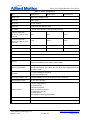
Allied Motion Technologies, Inc. 455 Commerce Drive, Suite 5 Amherst, NY 14228 (716) 242-7535 User Manual: xDrive Series Digital Brushless Servo Drives (Document Part Number: 34-2001 R2) Allied Motion Technologies, Inc. March 1, 2012 34-2001 R2 http://www.alliedmotion.com Page 1 of 35 xDrive Series Digital Brushless Servo Drives This manual describes the installation and operation of the xDrive series of digital brushless servo drives manufactured by Allied Motion Technologies, Inc. Every effort has been made to ensure the accuracy of the information in this manual. However, Allied Motion assumes no responsibility for any errors or omissions. The information contained in this document is subject to change without prior notice. We welcome your critical evaluation and suggestions for improvements to be made in future revisions. This manual is supplied to the user with the understanding that it will not be reproduced, duplicated, or disclosed in whole or in part without the express written permission of Allied Motion Technologies, Inc. Allied Motion Technologies, Inc. March 1, 2012 34-2001 R2 http://www.alliedmotion.com Page 2 of 35 xDrive Series Digital Brushless Servo Drives Table of Contents I. Tables .............................................................................................................................................. 5 II. Figures............................................................................................................................................. 6 III. Safety ............................................................................................................................................... 7 IV. Inspection upon Receipt ................................................................................................................ 8 1.0 Introduction .................................................................................................................................... 9 1.1 1.2 2.0 Product Description ............................................................................................................ 9 Features ............................................................................................................................... 9 1.2.1 Motor Command Modes ........................................................................................ 9 1.2.2 Motor Command Sources ...................................................................................... 9 1.2.3 Communications .................................................................................................... 9 1.2.4 Motor Feedback ..................................................................................................... 9 1.2.5 Fault Protection ...................................................................................................... 9 Installation and Wiring ............................................................................................................... 12 2.1 2.2 2.3 2.4 2.5 2.6 Grounding, Shielding, and Cabling .................................................................................. 12 2.1.1 Drive Grounding and Panel Layout ..................................................................... 12 2.1.2 Control Signal Cable and Shielding..................................................................... 15 2.1.3 Motor Feedback Cable and Shielding .................................................................. 15 2.1.4 Motor Cable and Shielding .................................................................................. 15 2.1.1 Line Filters ........................................................................................................... 15 USB Communications Connector ..................................................................................... 16 Control Connector (J16) ................................................................................................... 16 2.3.1 5 V Power Supply ................................................................................................ 16 2.3.2 Opto Inputs .......................................................................................................... 16 2.3.3 Opto Outputs ........................................................................................................ 18 2.3.4 Analog Inputs....................................................................................................... 18 2.3.5 Analog Output...................................................................................................... 19 2.3.6 Buffered Encoder Outputs ................................................................................... 19 Motor Feedback Connector (J23) ..................................................................................... 21 2.4.1 5 VDC Power Supply .......................................................................................... 21 2.4.2 Hall Sensor Inputs ................................................................................................ 21 2.4.3 Encoder Inputs ..................................................................................................... 22 2.4.4 Motor Temperature Sensor .................................................................................. 22 Logic Power Connector (J1) ............................................................................................. 23 Power Connector (J2) ....................................................................................................... 23 2.6.1 Regenerative Resistor Connections ..................................................................... 24 Allied Motion Technologies, Inc. March 1, 2012 34-2001 R2 http://www.alliedmotion.com Page 3 of 35 xDrive Series Digital Brushless Servo Drives 2.7 2.8 3.0 Motor Commutation and Feedback ........................................................................................... 27 3.1 3.2 3.3 4.0 4.3 4.4 Status Indicators................................................................................................................ 31 Fault Protection ................................................................................................................. 31 4.2.1 Over-voltage Detection ........................................................................................ 31 4.2.2 Under-voltage Detection ...................................................................................... 31 4.2.3 Over-Current Protection ...................................................................................... 31 4.2.4 Short Circuit Protection ....................................................................................... 32 4.2.5 Feedback Loss Detection ..................................................................................... 32 4.2.6 Drive Over-temperature ....................................................................................... 32 4.2.7 Motor Over-temperature ...................................................................................... 32 Fault Monitoring and Resetting ........................................................................................ 32 Troubleshooting ................................................................................................................ 32 4.4.1 Motor Does Not Move ......................................................................................... 32 4.4.2 Communication Errors ......................................................................................... 33 4.4.3 Erratic Motor Behavior ........................................................................................ 33 System Accessories ....................................................................................................................... 34 5.1 5.2 5.3 6.0 Commutation .................................................................................................................... 27 Motor Feedback Devices .................................................................................................. 27 3.2.1 Hall Sensors ......................................................................................................... 27 3.2.2 Incremental Encoder ............................................................................................ 27 Regeneration (Load Dump Capability) ............................................................................. 28 3.3.1 Regeneration Energy Explanation ....................................................................... 28 3.3.1.1 Stored Energy in Motor .......................................................................... 28 3.3.1.2 Energy Dissipated In the Motor While Decelerating .............................. 29 3.3.1.3 Energy Stored in the Bus Capacitor ........................................................ 29 3.3.1.4 Regenerative Energy to be Dissipated .................................................... 30 3.3.1.5 Pulse Power ............................................................................................ 30 3.3.1.6 Continuous Power Dissipated ................................................................. 30 Faults and Troubleshooting ........................................................................................................ 31 4.1 4.2 5.0 Motor Power (J3) .............................................................................................................. 25 Typical Wiring for Encoder Motor ................................................................................... 25 Mating Connectors and Cables ......................................................................................... 34 Recommended Regenerative Resistor Parts ..................................................................... 34 IN Control Software.......................................................................................................... 34 Revision History ........................................................................................................................... 35 Allied Motion Technologies, Inc. March 1, 2012 34-2001 R2 http://www.alliedmotion.com Page 4 of 35 xDrive Series Digital Brushless Servo Drives I. Tables Table 1: xDrive Specifications....................................................................................................... 10 Table 2: Environmental Specifications .......................................................................................... 11 Table 3: Control Connector (J16) .................................................................................................. 20 Table 4: Control Connector Mates ................................................................................................. 21 Table 5: Motor Feedback Connector (J23) .................................................................................... 22 Table 6: Motor Feedback Connector Mates ................................................................................... 23 Table 7: Logic Power Connector (J1) ............................................................................................ 23 Table 8: Logic Power Connector Mates ........................................................................................ 23 Table 9: Power Connector (J2) ...................................................................................................... 24 Table 10: Power Connector Mates ................................................................................................. 24 Table 11: Motor Power Connector (J3) ......................................................................................... 25 Table 12: Motor Power Connector Mates ...................................................................................... 25 Table 13: Regenerative Energy Storage......................................................................................... 30 Table 14: Fault LED Codes ........................................................................................................... 31 Table 15: Mating Connector Kit .................................................................................................... 34 Table 16: Assembled Cables .......................................................................................................... 34 Table 17: Recommended Regenerative Resistor Parts .................................................................. 34 Allied Motion Technologies, Inc. March 1, 2012 34-2001 R2 http://www.alliedmotion.com Page 5 of 35 xDrive Series Digital Brushless Servo Drives II. Figures Figure 1: xDrive Mounting Dimensions, inches [mm] .................................................................. 14 Figure 2: Schematic, Opto-Inputs 1 Through 4 ............................................................................. 17 Figure 3: Example, Opto-Input Voltage Sourcing ......................................................................... 17 Figure 4: Example, Opto-Input Voltage Sinking ........................................................................... 17 Figure 5: Schematic, Opto-Output ................................................................................................. 18 Figure 6: Example, Opto-Output Usage ........................................................................................ 18 Figure 7: Schematic, Analog Inputs 1 and 2 .................................................................................. 19 Figure 8: Schematic, Buffered Encoder Outputs ........................................................................... 19 Figure 9: Schematic, Hall Sensor/xDrive Interface ....................................................................... 21 Figure 10: Example, Regeneration Resistor Connections.............................................................. 24 Figure 11: Typical Wiring Diagram .............................................................................................. 26 Allied Motion Technologies, Inc. March 1, 2012 34-2001 R2 http://www.alliedmotion.com Page 6 of 35 xDrive Series Digital Brushless Servo Drives III. Safety Read all provided documentation before assembly and commissioning. Failure or incorrect or improper use of this equipment can cause death, personal injury and consequential damage. Allied Motion disclaims any responsibility for such occurrence whereby unskilled and/or untrained personnel have incorrectly installed the equipment. When this drive is powered, high voltages are present on the connector and elsewhere in the drive and can be dangerous. The drive cover should not be removed with the power on, and then only by a competent and trained engineer. It is important that all system components be properly grounded. Do not wire the drive and apply full power to it without checking it first at low power levels for correct operation. The final responsibility for the safe use of this motor is solely that of the user. Allied Motion has used its best effort in the preparation of this manual. We reserve the right to make modifications, and alterations to improve the content and amend errors may be made to it without notice. Check the appendices for errata and revisions. Allied Motion Technologies, Inc. March 1, 2012 34-2001 R2 http://www.alliedmotion.com Page 7 of 35 xDrive Series Digital Brushless Servo Drives IV. Inspection upon Receipt All Allied Motion products are thoroughly inspected and tested before leaving the factory. Although our products are packaged with extreme care, it is important that the user complete a thorough inspection of the product upon arrival. Examine the condition of the shipping container and materials. If damage is found, notify the commercial carrier involved. It is the user’s responsibility to file any necessary damage claims with the carrier. Our products are shipped EXW (ex works), unless other arrangements have been made. Allied Motion is not responsible for carrier mishandling. Allied Motion Technologies, Inc. March 1, 2012 34-2001 R2 http://www.alliedmotion.com Page 8 of 35 xDrive Series Digital Brushless Servo Drives 1.0 Introduction 1.1 Product Description The xDrive is a digital servo drive designed to work from single- or 3-phase 60 to 240 VAC. It is fully programmable and can work as a torque, velocity, or position servo drive. It supports feedback from Hall sensors and/or an incremental encoder. See Table 1 and Table 2 for important xDrive specifications. 1.2 Features 1.2.1 Motor Command Modes The motor command modes supported by the drive are current mode, torque mode, velocity mode, and position mode. 1.2.2 Motor Command Sources The motor command source can be derived from an analog input or a software parameter. 1.2.3 Communications The drive has a USB communication port for drive set-up. 1.2.4 Motor Feedback The drive can accept motor feedback from Halls only, or an incremental encoder with halls. In addition, the drive can accommodate a motor thermal sensor and can be set up to trip a fault for high motor temperatures. 1.2.5 Fault Protection The drive is protected from the following faults: output short-circuit, loss of motor feedback, DC bus over-voltage, motor over-current, and drive overtemperature. In addition the drive can be configured to read a motor temperature sensor and detect a motor over-temperature fault. Allied Motion Technologies, Inc. March 1, 2012 34-2001 R2 http://www.alliedmotion.com Page 9 of 35 xDrive Series Digital Brushless Servo Drives Table 1: xDrive Specifications Model DA-XDA-230-4-0 Amplifier Type PWM (10 kHz) 4-quadrant control Current Loop DQ PI at 100 µs Velocity Loop PID / PDF at 100 µs Position Loop Proportional with feed-forward at 400 µs Input Voltage 60-240 VAC, 50/60 Hz, single- or three-phase; 80 to 320 VDC Continuous Output Power (with 240 VAC, 50/60 Hz, singlephase input) 350 W 700 W 1400 W Continuous Output Power (with 240 VAC, 50/60 Hz, threephase input) 1100 W 2200 W 4400 W Continuous Output Current 4.0 A Pk (2.8 A RMS) 8.0 A Pk (5.6 A RMS) 16.0 A Pk (11.2 A RMS) Peak Output Current (2 seconds) 8.0 A Pk (5.6 A RMS) 16.0 A Pk (11.2 A RMS) 32.0 A Pk (22.4 A RMS) Supported Motor Feedback Halls; Incremental Encoder + Halls Incremental Encoder Input Up to 10 MHz, 3.3-5 V Hall Sensor Input Internal pull-ups provided; 5 V Hall excitation provided Analog I/O 2 inputs: ±10 V, 12-bit resolution 1 output: 0-5 V scalable to velocity, current, or other variables Digital I/O (programmable) 4 optically isolated inputs: 5-35 V programmable for end-of-travel limits, enable, reset 2 optically isolated outputs: open-collector, 35 V max, 50 mA (max), programmable for fault, zero-speed, at-speed Logic Power 24 V at 0.25 A available for external use 24 V logic power keep-alive input External Regen Resistor / Fuse Connection available for 10 ohm, 250 W dissipation (max), DCM-8 Fuse Motor temperature sensors PTC, NTC, NO, or NC switch Protection Features Over/under -voltage detection Over-current detection Full short-circuit protection Encoder / Hall signal loss detection Drive temperature monitoring I2-T current fold-back Motor temperature monitoring (programmable) Communication Interface USB optically isolated, 12 Mbit Minimum motor inductance 1 mH at 240 VAC Allied Motion Technologies, Inc. March 1, 2012 DA-XDA-230-8-0 34-2001 R2 DA-XDA-230-16-0 http://www.alliedmotion.com Page 10 of 35 xDrive Series Digital Brushless Servo Drives Table 2: Environmental Specifications Operating Ambient Temperature 0 to 45 °C Storage Ambient Temperature -40 to 70 °C Humidity 5% to 95% non-condensing Altitude 3300 feet (de-rate output 2% per 1000 feet above 3300 feet) Frequency: 10 to 55 Hz Amplitude: 0.075 mm Vibration (according to IEC 68, Parts 2-6) Cycles per axis (xyz): 10 Frequency sweep: 1 octave/minute Allied Motion Technologies, Inc. March 1, 2012 34-2001 R2 http://www.alliedmotion.com Page 11 of 35 xDrive Series Digital Brushless Servo Drives 2.0 Installation and Wiring This section summarizes the recommended practices for installation of servo equipment. These practices are based on and consistent with IEEE Standard 518-1982, “IEEE Guide for Installation of Electrical Equipment to Minimize Electrical Noise Inputs to Controllers from External Sources”, particularly Section 6, “Installation, Recommendations and Wiring Practices”. This standard must be followed during assembly of our product in a machine. Startup (that is, normal operation) of the xDrive is prohibited until the end-product complies with Directive 89/392/EEC (Machine Directive) and directive 89/336/EEC (EMC Directive). The machine manufacturer must prove that the complete system conforms to all relevant European Directives. All equipment grounding should also be in conformance with applicable national and local electrical codes. Failure to follow recommended procedures might result in incorrect system operation and void the product warranty. 2.1 Grounding, Shielding, and Cabling Proper grounding is absolutely necessary for the motor and drive to work properly in a system. There are several important system grounds that must be made. In addition, motion control servo systems contain circuitry that can be affected by electromagnetic interference (EMI). They also contain switching circuitry that can generate significant EMI at frequencies from 10 kHz to 300 MHz. The potential exists for this switching noise to interfere with the correct operation of both the servo system and any other electrical equipment in the vicinity. Immunity to and generation of EMI is greatly affected by installation techniques. This section describes panel layout, wiring, grounding, and shielding techniques effective in designing and integrating a servo system into your application. 2.1.1 Drive Grounding and Panel Layout The user will install the drive(s) in a ventilated, metal industrial cabinet. See Figure 1 for relevant mounting dimensions. How parts are placed on the sub-panel and on the enclosure door will play an important role in reducing the effects of EMI. When designing a control panel to receive the xDrive, the panel builder should recognize a servo system’s two worst enemies: heat generation and electrical noise. The importance of proper control panel layout cannot be overemphasized. First, it will set the stage for good noise-free wiring practices described later in this section. Second, it will minimize the effects of heat generation. Proper control panel layout can be achieved by observing the following simple rules: Allied Motion Technologies, Inc. March 1, 2012 34-2001 R2 http://www.alliedmotion.com Page 12 of 35 xDrive Series Digital Brushless Servo Drives The xDrive is mounted to a cabinet panel with two mounting screws. A mounting screw must connect the drive housing to earth ground. The screw will ground the drive housing provided the panel/cabinet containing the drive is metal and properly grounded. A star washer should be used under the mounting screw head to ensure good electrical contact between the drive and the screw. To obtain rated output current from the drives, the ambient air temperature below the drives must be held between -40 and 45 °C. No heat generating devices, such as transformers, power supplies, or power resistors, should be mounted directly beneath the drives. Allow a minimum clearance distance of 2 inches (52 mm) between the drive any other drive or component above, below, or on either side of the drive. Do not mix power and control signal wiring in the same conduit, duct, or wire tray without a minimum of 1 inch (26 mm) separation. Provide separate wire ways for main AC, low power AC, high power DC, and low power DC. Restrict all high voltage power wiring and power devices such as circuit breakers, contactors, fuses, etc., to an area separate from low-level control wiring. The area above the drives is to be used for the wiring of low level (noise sensitive) control signals, such as analog input and output signals and motor feedback signals. When mounting a unit, be sure to remove paint from the mounting surfaces to obtain metal-to-metal contact. Use a serrated washer (star washer) to improve the connection. If in doubt use a ground strap to ensure good connection between the unit and the enclosure. Use ground straps made of 1 inch (25 mm) silver tinned flat copper braid to connect cabinet doors to enclosures, the first sub-panel to the enclosure, and each sub-panel to the next. Where electrical codes call for green safety ground wires, use them in addition to any ground strap suggested in this guide. Follow the electrical codes for grounding of the main three-phase power transformer. Allied Motion Technologies, Inc. March 1, 2012 34-2001 R2 http://www.alliedmotion.com Page 13 of 35 xDrive Series Digital Brushless Servo Drives It is recommended that all heat-generating resistors be mounted outside the cabinet within a protective enclosure. The wiring must be properly strain relieved to ensure interconnects, wiring and terminal connections do not become damaged. Figure 1: xDrive Mounting Dimensions, inches [mm] Allied Motion Technologies, Inc. March 1, 2012 34-2001 R2 http://www.alliedmotion.com Page 14 of 35 xDrive Series Digital Brushless Servo Drives 2.1.2 Control Signal Cable and Shielding The control signals from the drive control source to the drive need to be run to the drive in a shielded cable. The cable shield should be tied to the shielded housing of the Control (J16) mating connector. It is also beneficial to run the control signals in twisted pairs for more noise reduction. Signals that are differential in nature should always be run in twisted pairs. The recommended control cable is 3M 3600B/26 cable, which is a 26-conductor (13 twisted pairs) 28 AWG shielded cable. 2.1.3 Motor Feedback Cable and Shielding The motor feedback signals need to be run from the motor to the drive using a shielded cable. The cable shield should be tied to the shielded housing of the Motor Feedback (J23) mating connector. It is also beneficial to run the motor feedback signals in twisted pairs for more noise reduction. Signals such as ENCOUTA+ and ENCOUTA- that are differential in nature should always be run in twisted pairs. The recommended motor feedback cable is 3M 3600B/20 cable, which is a 20conductor (10 twisted pairs) 28 AWG shielded cable. 2.1.4 Motor Cable and Shielding The recommended motor cable is a 4-conductor cable with shield. The wire size needs to be sufficient to accommodate the xDrive’s current output capability. The 4 A xDrive requires a minimum of 18 AWG wire. The 8 A xDrive requires a minimum of 16 AWG wire. The 16 A xDrive requires a minimum of 14 AWG wire. Larger wire than the minimum recommended size is acceptable. It is extremely important that the motor chassis is grounded to the xDrive. Without this ground connection, a significant increase in electrical noise may be picked up by the drive. This can result in erratic behavior of the motor in the system. Pin 1 of the Motor Power connector (J3) is dedicated to the motor ground. A wire of the same size as the motor phase wires should be connected from the motor frame to pin 1 of J3. If a motor cable shield is used on the motor cable, the shield should also be terminated at pin 1. 2.1.1 Line Filters AC power brought into the panel can allow EMI to enter the panel. This is especially true in facilities that have a large number of SCR controlled devices, such as variable speed drives and heating or welding devices. Line filters should be placed in the incoming power lines immediately after the safety circuits and before any critical control components. Allied Motion Technologies, Inc. March 1, 2012 34-2001 R2 http://www.alliedmotion.com Page 15 of 35 xDrive Series Digital Brushless Servo Drives The xDrive series drives have built-in suppressors to protect them from lineinduced noise and transients. However, these internal devices cannot prevent such noise from affecting other parts of the system, such as high-speed sensor inputs and analog circuits. Line filters are necessary to achieve conducted noise levels that meet requirements for the CE Mark. Mount filters as close as possible to the incoming power feed as practical. The incoming power feed should be as short and direct as possible. Do not bundle wiring from filtered sources together with unfiltered wiring. 2.2 USB Communications Connector The USB communication connector is a USB Type B connector. It is isolated from the drive and therefore requires USB power, which most host devices provide. 2.3 Control Connector (J16) The Control connector is a 3M 26-pin MDR connector. 2.3.1 5 V Power Supply 5 V is available on the Control connector pin 23 (5 V return on pin 13). Note that a combined maximum of 250 mA is available from the 5 V on the Control (J16) and Motor Feedback (J23) connectors. 2.3.2 Opto Inputs There are four optically isolated inputs available on pins 1 through 4. The common for the opto inputs is on pin 14. These inputs can be activated with voltages from 5 to 32 V. Activation of these inputs can be accomplished with voltage sourcing or voltage sinking circuitry. An example of each is shown below: Allied Motion Technologies, Inc. March 1, 2012 34-2001 R2 http://www.alliedmotion.com Page 16 of 35 xDrive Series Digital Brushless Servo Drives +3.3V 10K 10K 10K 10K TO uP OPTO IN 1 4.99K 4.99K 4.99K 4.99K 4.99K 4.99K 4.99K 4.99K TO uP OPTO IN 2 TO uP OPTO IN 3 TO uP OPTO IN 4 OPTO IN COMMON COM OPTO INPUT CONFIGURATION Figure 2: Schematic, Opto-Inputs 1 Through 4 +3.3V 10K TO uP 4.99K OPTO IN X 4.99K COM OPTO IN COMMON SOURCING CIRCUIT EXAMPLE Figure 3:VOLTAGE Example, Opto-Input Voltage Sourcing 10K OPTO IN COMMON TO uP OPTO IN X 4.99K 4.99K COM VOLTAGE SINKING CIRCUIT EXAMPLE Figure 4: Example, Opto-Input Voltage Sinking Allied Motion Technologies, Inc. March 1, 2012 34-2001 R2 http://www.alliedmotion.com Page 17 of 35 xDrive Series Digital Brushless Servo Drives 2.3.3 Opto Outputs There are two optically isolated outputs available on pins 16 and 17. The common for the opto outputs is on pin 15. These outputs can drive loads with voltages from 5 to 32 V. Load current can be up to 50 mA. The opto isolator output transistors are a Darlington configuration, which means that the voltage across the output transistor when it is on will be a minimum of approximately 1.5 V. The outputs are current sinking only. An example of how to connect a load to the output opto circuitry is shown below: +3.3V OUT1 FROM uP OPTO OUT COMMMON OUT2 FROM uP Figure 5: Schematic, Opto-Output OPTO OUTPUT CONFIGURATION OUTPUT LOAD +3.3V OUT1 FROM uP OPTO OUT COMMMON Figure 6: Example, Opto-Output Usage OUTPUT OPTO CIRCUIT EXAMPLE 2.3.4 Analog Inputs There are two differential analog inputs available. Analog Input 1 is on pins 10 and 12. Analog Input 2 is on pins 24 and 25. The two analog inputs are configured as in the circuit shown below. Each analog input has a differential receiver that is scaled to receive analog signals of ± 1 V. The analog input variables ADC1 and ADC2 represent the A/D conversion of the analog inputs. The A/D conversion accuracy is 12 bits. Allied Motion Technologies, Inc. March 1, 2012 34-2001 R2 http://www.alliedmotion.com Page 18 of 35 xDrive Series Digital Brushless Servo Drives 10K 1.50K Analog Input 1- - ADC1 + 10K +3.3V Analog Input 1+ 3.01K 3.01K COM Figure 7: Schematic, Analog Inputs 1 and 2 2.3.5 Analog Output There is an analog output available on pin 11. Its return pin is pin 13. Using the IN Control software application, parameters DAC1, DAC1MIN, and DAC1MAX configure and scale this output. 2.3.6 Buffered Encoder Outputs Encoder feedback outputs are on pins 5 and 18 (ENCOUTA+ and ENCOUTA-), pins 6 and 19 (ENCOUTB+ and ENCOUTB-) and pins 7 and 20 (ENCOUTZ+ and ENCOUTZ-). They are not optically isolated from the drive. ENCOUTA+ MOTOR ENCODER A ENCOUTA- ENCOUTB+ MOTOR ENCODER B ENCOUTB- ENCOUTZ+ MOTOR ENCODER Z ENCOUTZ- Figure 8: Schematic, Buffered Encoder Outputs Allied Motion Technologies, Inc. March 1, 2012 34-2001 R2 http://www.alliedmotion.com Page 19 of 35 xDrive Series Digital Brushless Servo Drives Table 3: Control Connector (J16) Pin No. Function Description Direction 1 Opto Input 1 Opto isolated input: 5-24 V, 5K impedance Input 2 Opto Input 2 Opto isolated input: 5-24 V, 5K impedance Input 3 Opto Input 3 Opto isolated input: 5-24 V, 5K impedance Input 4 Opto Input 4 Opto isolated input: 5-24 V, 5K impedance Input 5 ENCOUTA+ Motor Encoder A+ output Output 6 ENCOUTB+ Motor Encoder B+ output Output 7 ENCOUTZ+ Motor Encoder Z+ output Output 8 N/C No Connection N/C 9 N/C No Connection N/C 10 Analog Input 1 + ± 10 V Analog input 1 positive differential input Input 11 Analog Output 0-5 V Analog output Output 12 Analog Input 1 - ± 10 V Analog input 1 negative differential input Input 13 0V Common (for analog output, + 5 V power) I/O 14 Opto Input Common Common for opto isolated inputs I/O 15 Opto Output Common Common for opto isolated outputs I/O 16 OUT2 Opto isolated output: open collector, 24 V, 50 mA max Output 17 OUT1 Opto isolated output: open collector, 24 V, 50 mA max Output 18 ENCOUTA - Motor Encoder A- output Output 19 ENCOUTB - Motor Encoder B- output Output 20 ENCOUTZ - Motor Encoder Z- output Output 21 N/C No Connection N/C 22 N/C No Connection N/C 23 +5Volts Internal power supply available. A total of 250 mA is available for external Output use. 24 Analog Input 2 + +/- 10 V Analog input 2 positive differential input Input 25 Analog Input 2 - +/- 10 V Analog input 2 negative differential input Input 26 Screen Main screening earth I/O Allied Motion Technologies, Inc. March 1, 2012 34-2001 R2 http://www.alliedmotion.com Page 20 of 35 xDrive Series Digital Brushless Servo Drives Table 4: Control Connector Mates Connector Type MDR 2.4 Part No. 10126-3000PE 10326-3210-000 (cover) Manufacturer 3M Motor Feedback Connector (J23) The Motor Feedback connector is a 3M 20-pin MDR connector. 2.4.1 5 VDC Power Supply 5 VDC is available on the Motor Feedback connector pin 7 (5 V return on pin 11). This 5 VDC supply can be used for powering the Halls and the incremental encoder. 250 mA is available from this supply. However, note that if the 5 VDC supply on the Control connector (J16) is used to power an auxiliary device, that current is included in the 250 mA that is available. 2.4.2 Hall Sensor Inputs Hall sensor inputs are on pin 3 (Hall A), pin 13 (Hall B) and pin 2 (Hall C). The Hall sensor input circuitry in the drive is shown below. Open collector Hall sensor devices should be used. Pull-up resistors for the Hall sensors are provided in the drive. 5 VDC to power the Hall sensors is also provided by the xDrive. See Hall Sensors for more information on Hall sensor use and operation. MOTOR DRIVE +3.3V +5Volts HALLS 250ma PTC Fuse 331 V+ 331 331 HALLA TO uP HALLA 1K HALLB HALLB 1K HALLC TO uP HALLC COM TO uP 1K 1000pF 1000pF 1000pF 0Volts COM Figure 9: Schematic, Hall Sensor/xDrive Interface Allied Motion Technologies, Inc. March 1, 2012 34-2001 R2 http://www.alliedmotion.com Page 21 of 35 xDrive Series Digital Brushless Servo Drives 2.4.3 Encoder Inputs A differential incremental encoder is required by the drive if encoder feedback is used. Single-ended encoder operation is not permitted due to the high voltage of the drive and the potentially high electrical noise environment. The encoder signals are on pins 6 and 16 (A+ and A-), pins 5 and 15 (B+ and B-), and pins 4 and 14 (Z+ and Z-). See Incremental Encoder for more encoder detail. 2.4.4 Motor Temperature Sensor If your motor is provided with a thermal over-temperature (OT) switch or an NTC thermistor, it should be wired to the MotOT (pin 1) and 0Volts (pin 20) inputs on the Motor Feedback connector. Table 5: Motor Feedback Connector (J23) Pin No. Function Description Direction 1 Motor Temp Motor temperature sensor input Input 2 Hall C Hall Feedback sensor C (330 ohm pull-up to 3.3 V is internal to drive) Input 3 Hall A Hall Feedback sensor A (330 ohm pull-up to 3.3 V is internal to drive) Input 4 Z+ Encoder channel index input + Input 5 B+ Encoder channel B input + Input 6 A+ Encoder channel A input + Input 7 +5Volts Internal power supply available to power encoder and Halls. A total of 250 mA is available for external use. Output 8 N/C No Connection N/C 9 N/C No Connection N/C 10 N/C No Connection N/C 11 0Volts Common for feedback sensors I/O 12 N/C No Connection N/C 13 Hall B Hall Feedback sensor B (330 ohm pull-up to 3.3 V is internal to drive) Input 14 Z- Encoder channel index input - Input 15 B- Encoder channel B inverse input - Input 16 A- Encoder channel A inverse input - Input 17 0Volts Common for feedback sensors I/O 18 N/C No Connection N/C 19 N/C No Connection N/C 20 0Volts Common for motor temperature sensor I/O Allied Motion Technologies, Inc. March 1, 2012 34-2001 R2 http://www.alliedmotion.com Page 22 of 35 xDrive Series Digital Brushless Servo Drives Table 6: Motor Feedback Connector Mates Connector Type MDR 2.5 Part No. 10120-3000PE 10320-3210-000 (cover) Manufacturer 3M Logic Power Connector (J1) The Logic Power connector can be used to provide an external power source that will keep the drive control electronics active when high voltage main power is removed. Applying 24 VDC power from pin 1 to pin 2 will keep the drive control electronics active when main power is removed from the drive. This will enable the drive to properly track motor position with main power removed from the drive. The power requirements are 24 VDC ± 1 V at 1 A. Table 7: Logic Power Connector (J1) Pin No. Function Description Direction 1 L+ Logic supply holdup 24 V Input 2 L- Logic supply return I/O 3 N/C No Connection N/C Table 8: Logic Power Connector Mates 2.6 Connector Type Wire Gauge Part No. Manufacturer Screw Terminal 0.2 to 1.5 mm² 16 to 26 AWG OSTTJ0311530 On Shore Technology Screw Terminal 0.2 to 2.5mm² 16 to 26 AWG 1840379 Phoenix Power Connector (J2) The main power wiring is made to J2, the Power connector. Use care to ensure the correct pins are used for the main power. Improper wiring will result in damage to the drive. Ensure that the amplifier’s protective earth ground, pin 7, is taken directly to the panel’s single-point ground (SPG). See Grounding, Shielding and Cabling for more motor grounding information. If 3-phase AC power is used, it is connected to pins 4, 5, and 6. If single-phase AC power or DC power is used, it should be wired to pins 5 and 6. Connect an earthing wire to pin 7. The preferred AC line over-current protective device (one for each drive) is a three-phase magnetic circuit breaker with a 5-8x instantaneous trip point. Allied Motion Technologies, Inc. March 1, 2012 34-2001 R2 http://www.alliedmotion.com Page 23 of 35 xDrive Series Digital Brushless Servo Drives When operating from single-phase AC power, ensure that you take into account the drive’s following current derating: For single-phase AC, derate continuous current by 33% at 115 VAC and by 50% at 230 VAC. Failure to do so will result in damage to the drive and is not covered under the warranty. 2.6.1 Regenerative Resistor Connections Regenerative resistors are connected from pin 1 to pin 2 of J2 as shown below. See Regeneration (Load Dump Capability) for more information on regenerative circuitry. See Recommended Regenerative Resistor Parts for compatible parts and descriptions. J2 FUSE 1 2 3 4 5 6 7 DCM-8 L225J10RE 10 Ohms 225W Power Connector Figure 10: Example, Regeneration Resistor Connections Table 9: Power Connector (J2) Pin No. Function Description Direction 1 Regeneration External regeneration resistor connection I/O 2 High Voltage Bus Positive External regeneration resistor and/or capacitor connection I/O 3 High Voltage Bus Negative External bus capacitor connection I/O 4 WAC 60 to 240 VAC Input 5 VAC 60 to 240 VAC or 80 to 320 VDC Input 6 UAC 60 to 240 VAC or 80 to 320 VDC Input 7 Protective Earth Main screening earth I/O Table 10: Power Connector Mates Connector Type Wire Gauge Part No. Manufacturer Screw Terminal 0.5 to 3.4 mm² 12 to 24 AWG OSTTJ077150 On Shore Technology Screw Terminal 0.4 to 3.4 mm² 12 to 24 AWG 1754546 Phoenix Allied Motion Technologies, Inc. March 1, 2012 34-2001 R2 http://www.alliedmotion.com Page 24 of 35 xDrive Series Digital Brushless Servo Drives 2.7 Motor Power (J3) Utilize shielded four-conductor wiring with drain for motor power cabling. Follow electrical codes to ensure the proper wire gauge for the motor and drive is used. Provide a separate wireway for the high power cables to the motor. See Grounding, Shielding and Cabling for more motor grounding information. Table 11: Motor Power Connector (J3) Pin No. Function Description Direction 1 Protective Earth Main Screening Earth I/O 2 C Phase Motor Phase C Output (black lead) Output 3 B Phase Motor Phase B Output (white lead) Output 4 A Phase Motor Phase A Output (red lead) Output Table 12: Motor Power Connector Mates 2.8 Connector Type Wire Gauge Part No. Manufacturer Screw Terminal 0.5 to 3.4 mm² 12 to 24 AWG OSTTJ047150 On Shore Technology Screw Terminal 0.4 to 3.4 mm² 12 to 24 AWG 1754481 Phoenix Typical Wiring for Encoder Motor Typical wiring for a motor (with incremental encoder + Halls feedback) is shown in the figure below. It shows the proper connections and shielding for the motor cables. Proper shielding and grounding of the motor and its feedback devices is essential for proper operation of the motor. In particular, note both the grounding of the drive chassis to the cabinet ground (shown in the lower left corner) and the grounding of the motor housing to the drive. Allied Motion Technologies, Inc. March 1, 2012 34-2001 R2 http://www.alliedmotion.com Page 25 of 35 xDrive Series Digital Brushless Servo Drives Figure 11: Typical Wiring Diagram Allied Motion Technologies, Inc. March 1, 2012 34-2001 R2 http://www.alliedmotion.com Page 26 of 35 xDrive Series Digital Brushless Servo Drives 3.0 Motor Commutation and Feedback 3.1 Commutation Commutation is the process of determining the motor position and then applying the correct voltages to the three motor phases to induce current that produces the desired motor torque. The application of motor voltages is done with a Space Vector Modulation technique in the xDrive. There are several different motor feedback schemes used to determine motor position. The accuracies of these devices determine some of the characteristics of the currents produced in the motor. 3.2 Motor Feedback Devices 3.2.1 Hall Sensors Three Hall sensors, one for each phase, produce discrete signals indicating the motor’s rotor position to 60 electrical degrees of accuracy (electrical degrees in a motor are equal to mechanical motor shaft degrees divided by the number of motor pole pairs, or half of the number of motor poles). When used alone, Hall sensors can be used to run the motor in either current mode or velocity mode. Motor positioning is not possible when using only Hall sensors. When the drive is in Current mode, a constant current demand will produce motor currents with about 15% torque ripple. This assumes that the motor is sinusoidally wound, which is almost always the case with Allied Motion motors. When the drive is in Velocity mode, the speed of the motor can be controlled to about 5 revs/second at minimum. From 5 revs/sec to 0.5 revs/sec, the velocity of the motor becomes increasingly rough. Speed control of the motor below 0.5 revs/sec is not recommended, unless large variations in speed during a motor revolution can be tolerated. Hall sensors must also be used in conjunction with an incremental encoder. When the motor is first started, motor rotor position can only be known to within 60 electrical degrees by reading the Hall sensors. Once a Hall sensor transition is sensed, the motor position can then be tracked using the encoder. 3.2.2 Incremental Encoder An incremental encoder is used in conjunction with Hall sensors as a motor feedback system to generate both commutation and rotor position information. The encoder must be differential in nature, that is, it must have differential outputs of low impedance for each of its A, B and Z channels. Single-ended encoders are not permitted to be used with the xDrive due to noise issues caused by high voltage switching transients that may interfere with the low level singleended encoder signals. Allied Motion Technologies, Inc. March 1, 2012 34-2001 R2 http://www.alliedmotion.com Page 27 of 35 xDrive Series Digital Brushless Servo Drives Incremental encoders are defined by the line count of the device. That is, the number of reflective or transparent lines on the disk (rotary encoder) or in a specified length of the device (linear encoders). The xDrive uses the technique of quadrature interpolation to multiply the line count by a factor of four (4). Therefore, the encoder parameter EPPR is derived by multiplying the encoder line count four (4). As an example, a 500 line rotary encoder will have an effective resolution of 2000 counts per revolution (and an EPPR value of 2000) in the xDrive. The maximum read frequency for the encoder input of the xDrive is 20 MHz, so the maximum motor speed in RPM is determined by the equation: RPM (max) = 20,000,000/EPPR x 60 For instance, for a 2000 line encoder the max motor speed (encoder limited) would be 150,000 rpm. The direction of the incremental encoder is defined as positive when ENCA rises while ENCB is low. 3.3 Regeneration (Load Dump Capability) Regeneration occurs when the drive is commanded to remove energy from the system. This occurs most typically during a controlled deceleration of the motor. If the energy stored in the motor and the moving load exceeds the dissipation in the motor due to resistive losses (so-called I2R) during deceleration, then the excess energy must be handled by the drive (“load dump”). This energy is transferred through the drive and stored in the drive’s DC bus filter capacitors. As energy is stored, the DC bus voltage rises. If the DC bus voltage rises to 390 V, the drive will fault (Bus Over-voltage). This can be mitigated by connecting a regenerative resistor to the xDrive (see Regenerative Resistor Connections), which will dissipate the excess energy stored in the bus capacitors. Control circuitry in the drive switches the resistor across the DC bus when the bus voltage reaches 380 VDC. A 10 ohm, 225 W resistor (Ohmite L225J10RE, or equivalent) with an 8 A fuse (Bussmann DCM-8, or equivalent) in series can be added across pin 1 and pin 2 of the Power connector (J2) as the external regenerative dissipation resistor. The peak power which can be dissipated in this resistor is 14 kW. Internal protection mechanisms in the drive limit the average power dissipation in the resistor to 200 W. 3.3.1 Regeneration Energy Explanation 3.3.1.1 Stored Energy in Motor Energy is stored in the rotating motor and load inertias. Let the sum of these inertias = Jtot as reflected to the motor. Then the energy stored: Allied Motion Technologies, Inc. March 1, 2012 34-2001 R2 http://www.alliedmotion.com Page 28 of 35 xDrive Series Digital Brushless Servo Drives Es = ½ Jtot ω² where ω is the motor speed in rad/sec. 3.3.1.2 Energy Dissipated In the Motor While Decelerating As the drive decelerates the motor, there is an energy loss in the windings (I2R). This loss is: Pm = ¾ Rm (F/Kt)2 where Rm is the motor line to line resistance, F is the force applied to decelerate the motor, this is normally the motor peak current times Kt, and Kt is the motor torque constant. So the equation for Pm simplifes to: Pm = ¾ Rm (Ipeak)2 (i) However, if the I2t limit of the amplifier is exceeded, then current will be limited to the continuous current rating of the amplifier. In this case equation (i) becomes: Pm = ¾ Rm (Iconst)2 (ii) The actual value of Pm is normally between these two values, and tends towards (i) for low inertia loads and (ii) for high inertia loads. The energy loss is power loss x time or Em = Pm x deceleration time. 3.3.1.3 Energy Stored in the Bus Capacitor The regenerative energy storage capacity of the bus capacitors is a function of the difference between the voltage values squared of the capacitors when regeneration begins and the maximum value when the drive reaches its over-voltage sense point (390 V for a standard xDrive). Note that an external bus capacitor may be added to the xDrive, which will increase the energy storage capacity of the system. The regenerative energy storage is the following, where Vbus = 1.414 × RMS value of the input voltage; note that if a DC voltage, VDCin, is supplied to the drive, then Vbus = (VDCin - 3) VDC. Ec = ½ C [Vregen2– Vbus2] Allied Motion Technologies, Inc. March 1, 2012 34-2001 R2 http://www.alliedmotion.com Page 29 of 35 xDrive Series Digital Brushless Servo Drives Table 13: Regenerative Energy Storage Model Capacitance 120 VAC 220 VAC 240 VAC DA-XDA-230-4-0 390 F 22 J 9J 5.5 J DA-XDA-230-8-0 780 F 44 J 18 J 11 J DA-XDA-230-16-0 1170 F 66 J 27 J 16.5 J 3.3.1.4 Regenerative Energy to be Dissipated The regenerated energy to be dissipated then becomes: Eregen = Es - Em - Ec 3.3.1.5 Pulse Power The pulse power is the energy dissipated divided by the duration of the dissipation Pulse regenerative power (Ppulse) = Eregen/deceleration time 3.3.1.6 Continuous Power Dissipated The continuous power dissipated is the sum of the regenerative energy dissipated divided by the period of time for that dissipation: Average dissipated power = (Eregen1 + Eregen2 + Eregen3 +….) / time period. Allied Motion Technologies, Inc. March 1, 2012 34-2001 R2 http://www.alliedmotion.com Page 30 of 35 xDrive Series Digital Brushless Servo Drives 4.0 Faults and Troubleshooting 4.1 Status Indicators The xDrive is fitted with a bicolor LED which can indicate the status of the drive without the need to interrogate the drive through the communications bus. This is accomplished by displaying a combination of color and flash sequence. Table 14: Fault LED Codes 4.2 LED Action Status Slow blinking green Drive disabled with no faults Fast blinking green Drive enabled Red Drive faulted Fault Protection The following faults are detected and acted upon in the drive: 4.2.1 Over-voltage Detection The drive detects a DC bus voltage greater than 390 VDC. In this case the drive will disable and flag a Bus Over-voltage fault. If this happens to the drive, it will be necessary to add an external regeneration resistor (see section Regeneration (Load Dump Capability)) to dissipate excess regenerative energy. 4.2.2 Under-voltage Detection The drive detects a DC bus voltage less than 60 VDC when enabled. In this case the drive will disable and flag a Bus Under-voltage fault. 4.2.3 Over-Current Protection Peak currents are limited in the drive to the peak current rating of the drive. If the drive detects motor currents in excess of the peak drive limit, for instance due to poor current loop tuning of the motor, it will disable the drive and flag a Motor Over-current fault. Continuous currents are limited to the lesser of the continuous rated drive current or the motor continuous rated current (parameter IMAX of the drive’s Motor Parameters data). Continuous current limiting is accomplished with an I2T current limiting scheme. Allied Motion Technologies, Inc. March 1, 2012 34-2001 R2 http://www.alliedmotion.com Page 31 of 35 xDrive Series Digital Brushless Servo Drives 4.2.4 Short Circuit Protection The drive is fully protected from phase-to-phase and phase-to-ground short circuits in the motor or cabling. 4.2.5 Feedback Loss Detection Feedback loss is detected as follows: Hall sensor feedback: If an illegal Hall state is sensed (which will happen in the course of motor rotation if a Hall sensor lead is disconnected or shorted), the drive is disabled and a Hall Loss fault is flagged. Encoder/Hall sensor feedback: The drive is disabled and an Encoder Loss fault flag is set if there is a missing signal or shorted signal of any encoder line: A+, A-, B+, B-, Z+ and Z-. In addition, if an illegal Hall state is sensed a Hall Loss fault is flagged. 4.2.6 Drive Over-temperature The xDrive monitors the temperature of its power module. If the temperature of the module reaches 120 ºC, the drive is disabled and a Drive Over-temperature fault flag is set. The drive temperature can be monitored in the IN Control user interface by displaying the variable TPWR. 4.2.7 Motor Over-temperature Motor over-temperature is user configurable and is based upon the parameters MTB, MTOT and MTR0. If an NTC thermistor is installed as the motor temperature monitoring device, the motor temperature can be viewed by displaying the variable TMOT. 4.3 Fault Monitoring and Resetting Drive faults are indicated by a red drive LED. Faults can be reset either through the user interface, by assigning an input as a fault reset input or re-powering the drive. 4.4 Troubleshooting 4.4.1 Motor Does Not Move Configure the drive for your selected motor type and feedback type. Verify your motor parameters and Drive Mode parameter (DM). Allied Motion Technologies, Inc. March 1, 2012 34-2001 R2 http://www.alliedmotion.com Page 32 of 35 xDrive Series Digital Brushless Servo Drives Check to see if the drive is powered. The drive status LED blinking green slowly indicates that the drive is not faulted and not enabled. Fast blinking green indicates that the drive is enabled. Red indicates that a drive fault is present. In the event of a fault look at the Diagnose screen in the IN Control software. This page will display drive fault information and allow the fault to be cleared when problem is cleared. Verify that the motor current is set properly, and that an acceleration and velocity command other than zero was executed prior to the move command. Verify that current loop parameters are set properly. Verify that velocity loop parameters are set properly. Verify that hard-limit input is not active. Verify that the load is not jammed and that the brake, if present, is released. Verify that the motor is securely connected. Verify that you are supplying the correct AC voltage to the drive. Check parameter VDC in the monitor window. Check the motor wiring for loose connections or shorts. Verify that the I/O are correctly wired. 4.4.2 Communication Errors Check the communication cable for proper wiring and loose connections. Verify that the correct COM port is selected in the “Connect” drop-down of IN Control. 4.4.3 Erratic Motor Behavior Erratic motor behavior can be a result of improper motor and cable grounding. See Grounding, Shielding and Cabling for details. Allied Motion Technologies, Inc. March 1, 2012 34-2001 R2 http://www.alliedmotion.com Page 33 of 35 xDrive Series Digital Brushless Servo Drives 5.0 System Accessories 5.1 Mating Connectors and Cables Standard xDrive accessories, including mating connector kits and assembled cables as described below may be purchased from Allied Motion. Contact Allied Motion applications engineering to request further customization, such as additional cable lengths. Table 15: Mating Connector Kit Part No. Description DA-XDAKIT Mating connectors Connectors Included J1 mating connector, 3-pin screw terminal J2 mating connector, 7-pin screw terminal J3 mating connector, 4-pin screw terminal J16 mating connector, 26-pin MDR (w/solder terminals) J23 mating connector, 20-pin MDR (w/solder terminals) Table 16: Assembled Cables Part No. DA-XDACBLKIT-10 DA-XDACBLKIT-25 5.2 Description Control and Motor Feedback Cables, 10 ft length Control and Motor Feedback Cables, 25 ft length Function J16 mating connector to flying leads J23 mating connector to flying leads Recommended Regenerative Resistor Parts The peak power which can be dissipated using the following recommended parts is 14 kW. Internal protection mechanisms in the drive limit the average power dissipation in the resistor to 200 W. See Regeneration (Load Dump Capability) for more information. Table 17: Recommended Regenerative Resistor Parts Description Part No. Regen resistor L225J10RE Ohmite Resistor mounting clips 18E-100 Ohmite Fuse (8 A DC rated 600 V) DCM-8 Cooper Bussmann Fuse holder (DIN mount finger safe) CHCC1D 5.3 Manufacturer Cooper Bussmann IN Control Software IN Control is PC-based software that enables the user to configure the xDrive. Both the software and the manual for it are available for download at: http://controls.alliedmotion.com/Home.aspx Allied Motion Technologies, Inc. March 1, 2012 34-2001 R2 http://www.alliedmotion.com Page 34 of 35 xDrive Series Digital Brushless Servo Drives 6.0 Revision History Revision R1 R1.2 R1.3 R2 Description of Change Initial release. n/a n/a Reformatted document. Revised table headers and captions. Added power output specifications. Removed unsupported drive features (i.e. resolver, sin/cos encoder, high speed digital inputs). Reorganized content. Allied Motion Technologies, Inc. March 1, 2012 34-2001 R2 Date February 2010 June 2010 August 2011 February 2012 http://www.alliedmotion.com Page 35 of 35