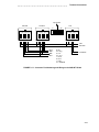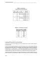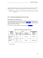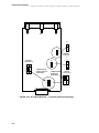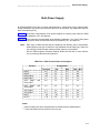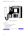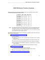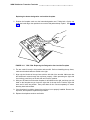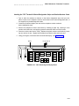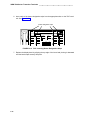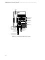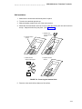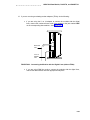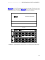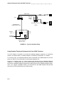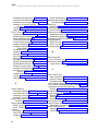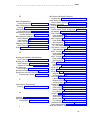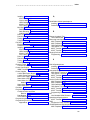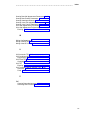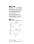
1
AT&T 555-021-101 Issue 3, February 1993 ISDN Installation and Test Manual b b 1 1993 AT&T All Rights Reserved Printed in USA Notice While reasonable effort was made to ensure that the information in this document was complete and accurate at the time of printing, AT&T cannot assume responsibility for any errors. Changes and/or corrections to the information contained in this document may be incorporated into future issues. Your Responsibility for Your System’s Security You are responsible for the security of your system. AT&T does not warrant that this product is immune from or will prevent unauthorized use of common-carrier telecommunication services or facilities accessed through or connected to it. AT&T will not be responsible for any charges that result from such unauthorized use. Product administration to prevent unauthorized use is your responsibility and your system administrator should read all documents provided with this product to fully understand the features available that may reduce your risk of incurring charges. Federal Communications Commission (FCC) Statement This equipment generates, uses, and can radiate radio-frequency energy and, if not installed and used in accordance with the instruction manual, may cause interference to radio communications. It has been tested and found to comply with the limits for a Class A computing device pursuant to Subpart J of Part 15 of FCC Rules, which are designed to provide reasonable protection against such interference when operated in a commercial environment. Operation of this equipment in a residential area is likely to cause interference, in which case the user at his/her own expense will be required to take whatever measures b b may be required to correct the interference. TRADEMARK NOTICE DEFINITY is a registered trademark of AT&T. ORDERING INFORMATION Call: AT&T Customer Information Center 1 800 432-6600 In Canada: 1 800 255-1242 Write: AT&T Customer Information Center 2855 North Franklin Road P.O. Box 19901 Indianapolis, IN 46219-1385 Order: Document No. AT&T 555-230-500ADD2 Issue 1, January 1993 Published by GBCSystems Product Documentation Development Group AT&T Bell Laboratories Middletown, NJ 07748-0076 2 aaaaaaaaaaaaaaaaaaaaaaaaaaaaaaaaaaaaaaaaaaaaaaaaaaaaaaaaaaaaaaaaaaaaaaaaaaa Contents Introduction …………………………………………………………………………………………… 1-1 Purpose of this Reissue ……………………………………………………………………………… 1-1 Organization of this Manual…………………………………………………………………………… 1-1 Important Warnings Before You Begin ……………………………………………………………… 1-2 Overview of Equipment …………………………………………………………………………… 2-1 Connecting Cords ……………………………………………………………………………………… 2-2 Terminating Resistor ………………………………………………………………………………… 2-4 Power Supplies ………………………………………………………………………………………… 2-6 Terminal Connections ……………………………………………………………………………… 3-1 Wiring Configurations ………………………………………………………………………………… 3-1 Modular Wall Jack Wiring Configurations …………………………………………………………… 3-2 103A/104A Connecting Block Internal Wiring ……………………………………………………… 3-5 Inside Wiring Termination on Cross-Connect Systems …………………………………………… 3-6 ANSI NT1-200 Installation …………………………………………………………………………… 3-8 AMI NT1 Installation …………………………………………………………………………………… 3-23 Bulk Power Supply …………………………………………………………………………………… 4-1 Auxiliary Power and Phantom Power Service ……………………………………………………… 4-3 The 1145A1 Bulk Power Supply and 1146A1 Power Distribution Unit…………………………… 4-7 ISDN 6500-Series U- and T-Interface Key Telephones ………………………………… 5-1 The 6504 Key Telephone …………………………………………………………………………… 5-1 Installing the 6504 Telephone………………………………………………………………………… 5-3 Testing the 6504 Telephone ………………………………………………………………………… 5-17 Removing the 6504 Telephone from Operation …………………………………………………… 5-20 The 6508 Key Telephone …………………………………………………………………………… 5-21 Installing the 6508 Telephone………………………………………………………………………… 5-23 Testing the 6508 Telephone ………………………………………………………………………… 5-32 Removing the 6508 Telephone from Operation …………………………………………………… 5-33 i aaaaaaaaaaaaaaaaaaaaaaaaaaaaaaaaaaaaaaaaaaaaaaaaaaaaaaaaaaaaaaaaaaaaaaaaaaa ISDN 7500-Series T-Interface Terminals …………………………………………………… 6-1 The 7505, 7506, and 7507 Terminals ……………………………………………………………… 6-2 Installing the 7505, 7506, and 7507 Terminals …………………………………………………… 6-6 Testing the 7500-Series Terminals ………………………………………………………………… 6-22 Removing 7500-Series Terminals from Operation ………………………………………………… 6-25 ISDN 8500-Series T-Interface Terminals …………………………………………………… 7-1 The 8503T Voice Terminal …………………………………………………………………………… 7-1 Installing the 8503T Voice Terminal ………………………………………………………………… 7-5 Testing the 8503T Voice Terminal …………………………………………………………………… 7-18 Removing the 8503T Voice Terminal from Operation……………………………………………… 7-21 The 8510T Voice Terminal …………………………………………………………………………… 7-22 Installing the 8510T Voice Terminal ………………………………………………………………… 7-25 Testing the 8510T Voice Terminal …………………………………………………………………… 7-48 Removing the 8510T Terminal from Operation …………………………………………………… 7-50 ISDN 7500 Data Module, PACKIT/6, and PACKIT/30 …………………………………… 8-1 The 7500 Data Module………………………………………………………………………………… 8-1 Installing the 7500 Data Module ……………………………………………………………………… 8-2 Testing the 7500 Data Module ……………………………………………………………………… 8-33 Removing the 7500 Data Module from Operation ………………………………………………… 8-38 The PACKIT/6 and PACKIT/30 ISDN PAD ………………………………………………………… 8-39 Installing the PACKIT/6 ……………………………………………………………………………… 8-44 Troubleshooting PACKIT/6 Problems ……………………………………………………………… 8-62 Adjunct Equipment Used with ISDN Terminals ………………………………………… 9-1 S201A Speakerphone ………………………………………………………………………………… 9-1 QUORUM CS201A Speakerphone ………………………………………………………………… 9-3 507 Adapter …………………………………………………………………………………………… 9-8 Headsets Used With the ISDN Terminals …………………………………………………………… 9-12 Administering Standard ISDN-1 Terminals for National ISDN ……………………… 10-1 Part 1: About ISDN 7506/7507 CPE ………………………………………………………………… 10-3 ii aaaaaaaaaaaaaaaaaaaaaaaaaaaaaaaaaaaaaaaaaaaaaaaaaaaaaaaaaaaaaaaaaaaaaaaaaaa Part 2: Initial Procedures ……………………………………………………………………………… 10-6 Part 3: Feature Button Programming………………………………………………………………… 10-14 Part 4: One Touch/Preselect Programming ………………………………………………………… 10-18 Part 5: Ringing Preference/Idle Preference Programming ………………………………………… 10-19 Part 6: X.25 Terminal Endpoint Identifier (TEI) Programming …………………………………… 10-20 Part 7: X.25 Conditional Notification Programming ………………………………………………… 10-23 Part 8: Data Call Appearance Programming ……………………………………………………… 10-24 Part 9: Voice Call Appearance Programming ……………………………………………………… 10-27 Part 10: Viewing Configuration Mode Parameters ………………………………………………… 10-30 Part 11: Basic Keysystem Voice Terminal Programming ………………………………………… 10-37 Part 12: Basic Call Voice Terminal Programming ………………………………………………… 10-41 Appendix A ……………………………………………………………………………………………… A-1 How to Determine Problems Between the Terminal and Network ……………………………… A-1 Appendix B ……………………………………………………………………………………………… B-1 Recommended Test Equipment ……………………………………………………………………… B-1 Appendix C ……………………………………………………………………………………………… C-1 D-Kits Used with the ISDN Telephones and Terminals …………………………………………… C-1 Index ……………………………………………………………………………………………………… I-1 iii aaaaaaaaaaaaaaaaaaaaaaaaaaaaaaaaaaaaaaaaaaaaaaaaaaaaaaaaaaaaaaaaaaaaaaaaaaa Introduction Introduction This manual is designed as a reference guide for the System Administrator (Telecommunications Manager) for each AT&T Integrated Services Digital Network (ISDN) system and the service technician responsible for installing the system. The document provides you with detailed instruction for installing telephone/terminal, supporting, and adjunct equipment required on the customer premises in support of ISDN, testing the equipment, and, for the telephones and terminals, removing the equipment from operation. Purpose of this Reissue The present issue of this manual, Issue 3, replaces all previous issues of this manual. Reasons for reissue include the following new equipment: d The 8503T and 8510T voice terminals d The NT1U-200 and NT1U-220 d The NT1M-200 and NT1M-210 d The NT1P-210 and NT1P-220 d The MSP-1 Power Supply d The 1145A1 Power Supply and 1146A1 Power Distribution Unit d The PACKIT/6 and PACKIT/30 ISDN PAD d The S201A Speakerphone d The QUORUM CS201A Speakerphone d The 507A Adapter d Appropriate headsets that can be used with ISDN terminals (and the 500A Headset Adapter) d The DLIT-200 Digital Line Test Set Organization of this Manual The remainder of this manual is divided into the following sections: d Overview of Equipment — Identifies the various items of hardware which may be required to support the terminals, key telephone, and data modules. Block diagram showing the locations of the various hardware items are included. d Terminal Connections — Provides detailed information necessary to connect the supporting equipment. 1-1 Introduction aaaaaaaaaaaaaaaaaaaaaaaaaaaaaaaaaaaaaaaaaaaaaaaaaaaaaaaaaaaaaa d Bulk Power Supply — Provides configuration and wiring information necessary to configure and connect the bulk power supply, specifically, the 1145A1/1146A1 bulk power arrangement. d ISDN 6500-Series U-Interface Key Telephones — Gives detailed instructions on installing, testing, and removing U- and T-interface ISDN 6504 and 6508 key telephones. d ISDN 7500-Series T-Interface Terminals — Gives detailed instructions on installing, testing, and removing ISDN 7505, 7506, and 7507 terminals. d ISDN 8500-Series T-Interface Terminals — Gives detailed instructions on installing, testing and removing ISDN 8503T and 8510T terminals. d ISDN 7500 Data Module, PACKIT/6, and PACKIT/30 — Gives detailed instructions on installing, testing, and removing the ISDN 7500 data modules and the PACKIT/6 and PACKIT/30 ISDN PAD. d Adjunct Equipment Used with ISDN Terminals — Gives information on connecting a 507A Adapter, S201A Speakerphone, CS201A Speakerphone, 500A Headset Adapter, and appropriate headsets to an ISDN terminal. d Administering Standard ISDN-1 Terminals for National ISDN — Gives procedures for configuring a standard ISDN terminal connected to the National ISDN. d Appendixes — Gives additional information on determining the source of problems, using recommended test equipment, and choosing the correct D-Kit for ISDN terminals. Important Warnings Before You Begin Read the following warnings before you begin installation: 1-2 WARNING: Do not connect any equipment into a modular wall jack until you are positive the wall jack is wired for the appropriate interface and power configuration. Doing so may cause damage to the equipment. The System 75/85 Port Tester can be used for this purpose if modular jack labeling is questionable or nonexistent. Refer to Appendix B for information on the System 75/85 Port Tester. WARNING: Do not plug the handset cord into the adjunct jack. Doing so will damage the telephone. CAUTION: Correct cord type must be used when connecting equipment. Failure to use the correct cord may cause malfunction to the equipment. CAUTION: Service technicians must always attach wrist-grounding straps before handling circuit packs, circuit boards, or internal terminal components. aaaaaaaaaaaaaaaaaaaaaaaaaaaaaaaaaaaaaaaaaaaaaaaaaaaaaaaaaaaaaaaa Overview of Equipment Overview of Equipment This section gives an overview of the various equipment that may be used to provide ISDN services to a customer. The equipment used with ISDN terminals includes the following: d Mounting cords d Terminating resistor adapters (TRA) d Power supplies The 945 Bulk Power Supply (no longer manufactured) The 1145A1 Bulk Power Supply and the 1146A1 Power Distribution Unit The 353A Stand-Alone Power Supply The KS-22911 Stand-Alone Power Supply The MSP-1 Stand-Alone Power Supply The WP90110 L7 Stand-Alone Power Supply for the 7500 Data Module d Network Termination 1 d Alternate Mark Inversion (AMI) Network Termination 1 [NT1U, NT1P, and NT1P-100 (phantom power)] d American National Standards Institute (ANSI) Network Termination 1 (NT1U-200, NT1P-210, NT1U-220, and NT1P-220) 2-1 Overview of Equipment aaaaaaaaaaaaaaaaaaaaaaaaaaaaaaaaaaaaaaaaaaaaaaaaaaaaa Connecting Cords The following three cords are used to connect ISDN customer premises equipment: D6AP-87, D8W-87, and D8AC. Figure 2-1 shows the wiring schematics of these cords. (Figure 2-1 also includes schematics of two older cords, the DW4A-SE and the D4BU, although, for the most part, these cords are no longer used.) The D6AP-87 cord consists of six conductors terminated in a 6-position plug on each end. It is used to connect: d The stand-alone AMI NT1 to the stand-alone power supply (353A) d The 6504A and T-interface key telephone d The 6508A key telephone to the stand-alone power supply and to the wall jack d The stand-alone power supply to the wall jack d The 400B2 adapter to the wall jack In a bulk power arrangement, it is used to connect the bulk power unit to the NT1 module. The D8W-87 cord consists of eight conductors terminated in an 8-position plug on each end. It is used to connect ISDN terminals to the stand-alone power supply or stand-alone ANSI NT1. A standard 7-foot (210 cm) cord is typically provided with the terminal. The D8AC cord is used to attach adjunct equipment to the terminals. 2-2 aaaaaaaaaaaaaaaaaaaaaaaaaaaaaaaaaaaaaaaaaaaaaaaaaaaaaaaaaaaaaaaa BK R G Y Overview of Equipment 1 DW4A-SE 6 CORD CONNECTIONS LOOSE WIRE PLUG PIN NO. 1 BLACK 2 RED 3 GREEN 4 YELLOW 5 6 1 86 PIN NUMBERS TYPICAL PLUG NUMBERING 6 1 1 D4BU 6 5 43 21 PLUG A CORD CONNECTIONS 6 PLUG B PLUG A PIN NO. PLUG B PIN NO. 6* 1* 2 5 3 4 4 3 5 2 1* 6* * NO CONDUCTOR PROVIDED 876 543 21 6 1 D6AP-87 1 PLUG A CORD CONNECTIONS PLUG A PIN NO. 6 5 4 3 2 1 1 6 PLUG B PLUG B PIN NO. 1 2 3 4 5 6 1 D8W-87 AND D8AC 8 8 PLUG A CORD CONNECTIONS PLUG A PIN NO. PLUG B PIN NO. 1 1 2 2 3 3 4 4 5 5 6 6 7 7 8 8 PLUG B FIGURE 2-1. Wiring Schematics for Mounting Cords 2-3 Overview of Equipment aaaaaaaaaaaaaaaaaaaaaaaaaaaaaaaaaaaaaaaaaaaaaaaaaaaaa Terminating Resistor The terminating resistor reduces transmission reflections on the T-interface. In most cases, both ends of the T-interface require a resistor; Basic MultiPoint is the exception. Note: This document does not cover MultiPoint installation. For more information about MultiPoint, see the Customer Premises Planning Guide, 533-700-100. Consider the following information about terminating resistors: d The T-card in the switch incorporates a 100 Ohm terminating resistor. d The T-interface portion of the NT1 includes three options: 50 Ohms, 100 Ohms and High Impedance (>2000 Ohms). d The 8500-Series terminals support a 100 Ohm or High Impedance option. All other AT&T terminals appear as High Impedance. d The 440A4 terminating resistor adapter for use at the set is 100 Ohms. d The 110RA1-12 terminating resistor block provides the 100 Ohm resistance for 12 lines. Note: High Impedance acts like an open circuit, preventing the receiver from reducing transmission efficiency. The 100 Ohm resistances balance the transmission path, improving signal recognition in the receiver. Remember the following in selecting 100 Ohm, 50 Ohm, or High Impedance in the NT1: d Selecting the 100 Ohm option in the NT1 requires a 100 Ohm resistance in the transmission path. For single terminal interfaces, the best transmission results when the 440A4 terminating resistor adapter is placed near the set. For uniform procedures, install the 440A4 at the information outlet. When using the 440A4, ISDN terminals should be High Impedance. The 8503T may be optioned for 100 Ohms, but in this case, do not use the 440A4. For Branched MultiPoint, use the 110RA1-12 to provide the 100 Ohm termination before the branch. d Select the 50 Ohm option when the NT1 is installed in an office with the ISDN station or when the NT1 will be rack-mounted less than 250 cable feet (24 gauge DIW) from the ISDN stations (Basic MultiPoint, up to 4 stations). The ISDN terminals should be High Impedance. d Select the High Impedance option for the Short MultiPoint arrangement and place the 440A4 terminating resistor adapter at both information outlets. Up to four ISDN terminals can be connected after both 440A4 adapters. In this arrangement, the NT1 appears in the middle of the transmission path and the two information outlets are at the ends. Note: 2-4 The circuitry of the 8500-Series terminals contains a set of terminating resistor jumpers, labeled ON and OFF. ON enables the terminating resistor, and OFF bypasses the terminating resistor. The installer can change the terminating resistor options by changing these jumper settings. aaaaaaaaaaaaaaaaaaaaaaaaaaaaaaaaaaaaaaaaaaaaaaaaaaaaaaaaaaaaaaaa Overview of Equipment Figure 2-2 shows the ISDN 440A4 8-pin terminating resistor adapter for the terminal end of the 4-wire line. The terminating resistor adapter does not provide lightning or power-cross protection, and plugs into the line jack of the T-interface terminal. The procedures for selecting NT1 options are in the next section, Terminal Connections. The AMI NT1 uses jumper straps; the ANSI NT1 uses external mini-switches to control the options. 1.3" (3.25 CM) SHORT (15 IN, 37.5CM) PERMANENTLY ATTACHED CORD 3.5" (8.75 CM) 0.75" (1.8 CM) PLASTIC HOUSING CORD R P L U G 1 2 3 4 5 6 7 8 T (+) R (+) R (-) T (-) C R C T (+) R (+) R (-) T (-) 1 2 3 4 5 6 7 8 J A C K FIGURE 2-2. 8-Pin Terminating Resistor Adapter 2-5 Overview of Equipment aaaaaaaaaaaaaaaaaaaaaaaaaaaaaaaaaaaaaaaaaaaaaaaaaaaaa Power Supplies Power for ISDN equipment may be provided by bulk power supplies (the 1145A1/1146A1 power arrangement, the 945, or the 346) or stand-alone power supplies (the MSP-1 is the newer power supply; the 353A and KS-22911 are older power supplies). Bulk Power Supplies Bulk power supplies are located in equipment rooms or wiring closets within recommended distances. The bulk power supplies may include reserve power capability. The bulk power supplies power for NT1s, and the individual terminals and key telephones. Detailed information concerning bulk power supply configurations and connections is described in the section titled Bulk Power Supply. Stand-Alone Power Supplies This type of power supply is a stand-alone unit (Figure 2-3 shows a 353A Power Supply) located near the equipment being served. Attached to the unit is a 6-foot (180 cm) AC power cord with a convenience outlet on the plug end. Connections are made via one 8-pin and two 6-pin jacks located in the front of the 353A unit or on the 400B2 adapter used with the KS-22911. Figure 2-4 shows the connections between these jacks on the 353A Power Supply as well as the power wiring. The 353A power supply can supply 100 milliseconds (ms) holdover for up to 12 watts of load. If additional holdover time is required, the bulk power supplies and reserve battery unit must be used. The MSP-1 Power Supply replaces the KS-22911-L1/2, 329A, and 353A DC Power Supplies and the 2012D AC Transformer. It has a single output of -48 volt DC, 0.4 amperes, and can operate from either a 120 VAC 60 Hz. Power source (105 to 129 VAC) or a 220/230/240 50 Hz. Power source (198 to 264 VAC). Input voltage selection is automatic; that is, the power supply adjusts itself for the type of input voltage. The output capacity is 19.2 watts. Figure 2-6 shows the power wiring on the MSP-1. CAUTION: The MSP-1 has an 8-pin Line jack; an AMI NT1 has a 6-pin Line jack. When planning the installation of an MSP-1, use an 8-pin wall jack. Continued insertion of a D6AP plug into an RJ-45, such as a wall jack, will eventually deform the outer two contacts on the RJ-45 and cause faulty connections. Use the WP90110 L7 stand-alone power supply for the 7500 data module. Do not use the MSP-1, 353A, or KS-22911 stand-alone power supply for the 7500 data module. 2-6 aaaaaaaaaaaaaaaaaaaaaaaaaaaaaaaaaaaaaaaaaaaaaaaaaaaaaaaaaaaaaaaa Overview of Equipment 4 1/2" (11.25 CM) 2 1/2" (6.25 CM) PH TO ON E TO NT 1 T LINO E 3 1/2" (8.75 CM) FIGURE 2-3. The 353A Stand-Alone Power Supply 2-7 Overview of Equipment aaaaaaaaaaaaaaaaaaaaaaaaaaaaaaaaaaaaaaaaaaaaaaaaaaaaa To Line To AMI NT 1 To Phone or ANSI NT 1 6 5 4 3 2 1 6 5 4 3 2 1 8 7 6 5 4 3 2 1 –40V GND FIGURE 2-4. 353A Stand-Alone Power Supply Wiring Note: The contacts of the jacks are numbered from left to right looking at the front of the jack. The 6-pin plug is compatible with the 8-pin jack. The D6AP cord reverses the polarity of the pins; the D8W cord does NOT reverse the polarity of the pins. The TO LINE 6-pin jack is used to connect to the U- or T-interface. This line is kept separate from the -40 volts and is internally connected to both output jacks. The signals on this line pass through the power supply without modification. Table 2-A shows connections possible with the stand-alone power supply. 2-8 aaaaaaaaaaaaaaaaaaaaaaaaaaaaaaaaaaaaaaaaaaaaaaaaaaaaaaaaaaaaaaaa Overview of Equipment TABLE 2-A. Stand-Alone Power Supply Jack Connections bbbbbbbbbbbbbbbbbbbbbbbbbbbbbbbbbbbbbbbbbbbbbbbbbbbbbbbbbbbbbbbbbb c c POWER SUPPLY JACK bbbbbbbbbbbbbbbbbbbbbbbbbbbbbbbbbbbbbbbbbbbbbbbbbbbbbbbbbbbbbbbbbb c c c c c c TO LINE TO NT1 TO PHONE c c bbbbbbbbbbbbbbbbbbbbbbbbbbbbbbbbbbbbbbbbbbbbbbbbbbbbbbbbbbbbbbbbbb c c c c T-Interface Wall Jack c T-Interface Terminal c c c c c c without local NT1 c c c bbbbbbbbbbbbbbbbbbbbbbbbbbbbbbbbbbbbbbbbbbbbbbbbbbbbbbbbbbbbbbbbbb c c c c U-Interface c c c U-Interface Wall Jack c Key Telephone c c c cbbbbbbbbbbbbbbbbbbbbbbbbbbbbbbbbbbbbbbbbbbbbbbbbbbbbbbbbbbbbbbbbbb c c c c NT1 c c c U-Interface Wall Jack c c c (Connection to c c c T-interface terminal) c c c c c c c bbbbbbbbbbbbbbbbbbbbbbbbbbbbbbbbbbbbbbbbbbbbbbbbbbbbbbbbbbbbbbbbbb The MSP-1 Power Supply The power output on the MSP-1 Power Supply is provided through three modular jacks on the power supply. These jacks are labeled, from left to right. PHONE -7 +8 OTHER -2 +5 LINE The - and + numbers under ‘‘PHONE’’ and ‘‘OTHER’’ refer to the pins in which power is present. The PHONE and LINE jacks are 8-pin female non-keyed 657-type jacks that can accept D4, D6, and D8 modular plug cables. The OTHER jack is a 6-pin female non-keyed 657-type jack. CAUTION: An MSP-1 has an 8-pin Line jack; an AMI NT1 has a 6-pin Line jack. When planning an installation using an MSP-1, you must use an 8-pin wall jack. Figure 2-5 shows the local power arrangement for adjuncts connected to ISDN-T voice terminals, and for ISDN-T voice terminals (without adjuncts). The type of cord(s) needed to make these connections are designated in the drawing. Note: If a T-interface voice terminal is used with the MSP-1, an NT1U-200 should also be used. Refer to Figure 2-6 for the power wiring on the MSP-1. 2-9 Overview of Equipment aaaaaaaaaaaaaaaaaaaaaaaaaaaaaaaaaaaaaaaaaaaaaaaaaaaaa MSP-1 Power Supply PHONE OTHER -7 +8 -2 +5 LINE D8W cord Back view of voice terminal D8W cord 657E Adjunct jack Line jack Wall jack FIGURE 2-5. Local Powering Arrangement for MSP-1 Connected to ISDN Terminals with NT1 in Closet 2-10 aaaaaaaaaaaaaaaaaaaaaaaaaaaaaaaaaaaaaaaaaaaaaaaaaaaaaaaaaaaaaaaaa Terminal Connections Terminal Connections Wiring Configurations Before connecting any device to the modular wall jack, you need to know the following: d Type of interface available at the wall jack d Type of equipment being connected d If power is provided at the wall jack d If multiple mount (modular) Network Termination 1 (NT1) is used 3-1 Terminal Connections aaaaaaaaaaaaaaaaaaaaaaaaaaaaaaaaaaaaaaaaaaaaaaaaaaaaaa Modular Wall Jack Wiring Configurations Figures 3-1 through 3-6 show modular wall jack wiring configurations. Note: The contacts of the jacks are numbered from left to right at the front of the jack. OPEN OPEN TRANSMIT (+) RECEIVE (+) RECEIVE (-) TRANSMIT (-) -40 V DC GROUND 1 2 3 4 5 6 7 8 FIGURE 3-1. T-Interface Configuration for 8-Pin Connections with Bulk Power OPEN OPEN TRANSMIT (+) RECEIVE (+) RECEIVE (-) TRANSMIT (-) OPEN OPEN 1 2 3 4 5 6 7 8 FIGURE 3-2. T-Interface Configuration for 8-Pin Connections with Stand-Alone Power 3-2 aaaaaaaaaaaaaaaaaaaaaaaaaaaaaaaaaaaaaaaaaaaaaaaaaaaaaaaaaaaaaaaaa Terminal Connections OPEN OPEN OPEN SIGNAL SIGNAL OPEN -40 V DC GROUND 1 2 3 4 5 6 7 8 FIGURE 3-3. ANSI U-Interface Configuration for 8-Pin Connections with Bulk Power OPEN OPEN OPEN SIGNAL SIGNAL OPEN OPEN OPEN 1 2 3 4 5 6 7 8 FIGURE 3-4. ANSI U-Interface Configuration for 8-Pin Connections with Stand-Alone Power 3-3 Terminal Connections aaaaaaaaaaaaaaaaaaaaaaaaaaaaaaaaaaaaaaaaaaaaaaaaaaaaaa OPEN -40 V DC SIGNAL SIGNAL GROUND OPEN 1 2 3 4 5 6 FIGURE 3-5. U-Interface Configuration for 6504A and 6508A with Bulk Power OPEN OPEN SIGNAL SIGNAL OPEN OPEN 1 2 3 4 5 6 FIGURE 3-6. U-Interface Configuration for 6504A and 6508A with Stand-Alone Power 3-4 aaaaaaaaaaaaaaaaaaaaaaaaaaaaaaaaaaaaaaaaaaaaaaaaaaaaaaaaaaaaaaaaa Terminal Connections 103A/104A Connecting Block Internal Wiring Figure 3-7 shows the internal wiring of the 103A and 104A connecting block and its integral 641A jack. The figure also shows the correlation between the modular jack pin assignments and the PDS wiring. W-BL BL W-O O W-G G W-BR BR 5 7 4-PAIR D-INSIDE WIRE 1 2 BL-W BL 3 W 4 Y 6 R BK 8 BR-W BR TERMINAL BLOCK ON UNIT 5 1 3 7 4 2 6 8 641A JACK 1 2 3 4 5 6 7 8 FIGURE 3-7. 103A/104A Connecting Block — Internal Wiring 3-5 Terminal Connections aaaaaaaaaaaaaaaaaaaaaaaaaaaaaaaaaaaaaaaaaaaaaaaaaaaaaa Inside Wiring Termination on Cross-Connect Systems Tables 3-A and 3-B list the termination of 4-pair inside wiring on 110 and 66 cross-connect systems. TABLE 3-A. 4-Pair Inside Wire Termination on 110 Cross-Connect bbbbbbbbbbbbbbbbbbbbbbbbbbbbbbbbbbbbbbbb c c cc c Position c Color Position Color c c cc cbbbbbbbbbbbbbbbbbbbbbbbbbbbbbbbbbbbbbbbb c c c c cc c 1 25 c W-BL c c W-BL c c c 2 26 c BL c c BL cc c c W-O c c W-O c c c 3 27 c c O cc c O c 4 28 c c cc c c 5 W-G 29 W-G c c cc c c 6 30 c c G cc c G c 7 31 c W-BR c c W-BR c c c c c BR cc c BR cbbbbbbbbbbbbbbbbbbbbbbbbbbbbbbbbbbbbbbbb 8 32 c c c cc c c W-BL c c W-BL c c c 9 33 c c BL cc c BL c 10 34 c c c c 11 W-O c c 35 W-O c c cc c c 12 36 c c O cc c O c 13 37 c W-G c c W-G c c c c c G cc c G c 14 38 c W-BR c c W-BR c c c 15 39 c c BR cc c BR c 16 40 b c c cc c c bbbbbbbbbbbbbbbbbbbbbbbbbbbbbbbbbbbbbbb c W-BL c c W-BL c c c 17 41 c c cc c c 18 42 c c BL cc c BL c 19 43 c W-O c c W-O c c c c c O cc c 0 c 20 44 c c c c c 21 W-G 45 W-G c c c c c c c 22 G 46 G c c cc c c 23 47 c W-BR c c c W-BR c c 24 48 cc BR cc cc BR cc cc ccbbbbbbbbbbbbbbbbbbbbbbbbbbbbbbbbbbbbbbbb Note: 3-6 Positions 49 and 50 are vacant. aaaaaaaaaaaaaaaaaaaaaaaaaaaaaaaaaaaaaaaaaaaaaaaaaaaaaaaaaaaaaaaaa Terminal Connections TABLE 3-B. 4-Pair Inside Wire Termination on 66 Cross-Connect b bbbbbbbbbbbbbbbbbbbbbbbbbbbbbbbbbbbbbbbbbbbbbbbb c c c cc c Position Color Position Color c c c cc cb bbbbbbbbbbbbbbbbbbbbbbbbbbbbbbbbbbbbbbbbbbbbbbbb c c c cc c c Pair 1 T (1) c W-BL c c Pair 13 T (13) c W-BL c c c c Pair 13 R (13) c BL c Pair 1 R (1) c BL c Pair 2 T (2) c W-O c c Pair 14 T (14) c W-O c c c c Pair 14 R (14) c O c Pair 2 R (2) c O c c cc c c c Pair 3 T (3) c W-G c c Pair 15 T (15) c W-G c c c c Pair 15 R (15) c G c Pair 3 R (3) c G c Pair 4 T (4) c W-BR c c Pair 16 T (16) c W-BR c c c c Pair 16 R (16) c BR cb bbbbbbbbbbbbbbbbbbbbbbbbbbbbbbbbbbbbbbbbbbbbbbbb Pair 4 R (4) c BR c c cc c c c Pair 5 T (5) c W-BL c c Pair 17 T (17) c W-BL c c c c Pair 17 R (17) c BL c Pair 5 R (5) c BL c c cc c c Pair 6 T (6) W-O Pair 18 T (18) W-O c c cc c c c c c Pair 18 R (18) c O c Pair 6 R (6) c O c Pair 7 T (7) c W-G c c Pair 19 T (19) c W-G c c c c Pair 19 R (19) c G c Pair 7 R (7) c G c Pair 8 T (8) c W-BR c c Pair 20 T (20) c W-BR c c c c Pair 20 R (20) c BR c Pair 8 R (8) c BR b c c cc c c bbbbbbbbbbbbbbbbbbbbbbbbbbbbbbbbbbbbbbbbbbbbbbbb c Pair 9 T (9) c W-BL c c Pair 21 T (21) c W-BL c c c cc c c c c c Pair 21 R (21) c BL c Pair 9 R (9) c BL c Pair 10 T (10) c W-O c c Pair 22 T (22) c W-O c c c c Pair 22 R (22) c O c Pair 10 R (10) c O c Pair 11 T (11) c W-G c c Pair 23 T (23) c W-G c c c c Pair 23 R (23) c G c Pair 11 R (11) c G c c cc c c c Pair 12 T (12) c W-BR c c Pair 24 T (24) c W-BR c 12 R (12) cc BR Pair 24 R (24) cc BR c Pair cc cc cc cb bbbbbbbbbbbbbbbbbbbbbbbbbbbbbbbbbbbbbbbbbbbbbbbb Note: Pair 25 is vacant. 3-7 Terminal Connections aaaaaaaaaaaaaaaaaaaaaaaaaaaaaaaaaaaaaaaaaaaaaaaaaaaaaa ANSI NT1-200 Installation The Stand-Alone NT1 The NT1 provides a conversion between the 2-wire U-interface and the 4-wire T-interface and can support Point-to-Point and MultiPoint ISDN services. The ANSI NT1U-200 The NT1U-200 supports the ANSI U-interface; that is, it is a type of stand-alone NT1 with the U-DSL implemented according to the 2B1Q ANSI standard. It can be installed at the work location or a wiring closet in an NT1M-200 rack. When at the work location, it can be mounted with either screws or magnetic strips. When it is in the wiring closet, it is mounted in the NT1M-200. Each NT1U-200 consumes 1.2 watts of power. The NT1U-200 supports phantom powering of ISDN terminals. Important: Note: When connecting the ANSI NT1, you must use a D8W cord. The newest NT1U model is the NT1U-220. For the few differences between the NT1U-220 and the NT1U-200 described here (and the differences between the NT1P-220 and the NT1P-210), see "The NT1U-220 Local Unit and the NT1P-220 Circuit Card" later in this section. However, note that the NT1U-200 and the NT1U-220 are installed in the same manner. So, in this section, when installation instructions and considerations are described for the NT1U-200, they also apply to the NT1U-220. For information on the AMI NT1U, see ‘‘AMI NT1 Installation’’ later in this section. User data is transmitted in a 2B+D format: two 64 kbits B-channels for voice and nonvoice communication and one 16 kbits D-channel for packet mode oriented signaling, low speed data and teleaction services. The NT1U-200 must be in the same building as the terminal; that is, there can be no outside plant wiring between the NT1U-200 and the ISDN terminal equipment. The NT1 type must match the line card type; that is, the NT1U-200 can only connect to an ANSI loop. Figures 3-8 and 3-9 show typical installation configurations with two different types of power supplies. For installation instructions, see ‘‘Installing the ANSI NT1U-200.’’ 3-8 aaaaaaaaaaaaaaaaaaaaaaaaaaaaaaaaaaaaaaaaaaaaaaaaaaaaaaaaaaaaaaaaa Terminal Connections Figure 3-8 shows the NT1U-200 powered by a 353A Power Supply. 6-pin jack or 8-pin jack 353A Power Supply TO NE HO TO L INT TO E LIN P D6AP cord Not used D8W cord To terminal D8W cord FIGURE 3-8. The NT1U-200 Powered by a 353A Power Supply Figure 3-9 shows the NT1U-200 powered by a KS-22911 Power Supply. KS-22911 Power Supply AC outlet D6AP cord 8-pin jack 400B2 Adapter D8W cord To terminal D8W cord FIGURE 3-9. The NT1U-200 Powered by a KS-22911 Power Supply 3-9 Terminal Connections aaaaaaaaaaaaaaaaaaaaaaaaaaaaaaaaaaaaaaaaaaaaaaaaaaaaaa Installing the NT1U-200 The NT1U-200 package contains the following items: (quantities are shown in parentheses) d The NT1U-200 unit (1) d Mounting plate with magnetic strip (1) d Plugs, mounting screws, and washers (2 of each) The following is the suggested installation procedure for the NT1U-200. Note: Do not mount the NT1U-200 within 12 inches of a heat source. 1. Preinstallation check. 2. Check that the DIP switch settings are correct for the premises wiring configuration. See ‘‘NT1U-200 DIP Switch Settings’’ later in this section. 3. Observe precautions for handling electrostatic devices (NT1U). 4. Mount NT1U-200. 5. Connect cables. 6. Connect NT1U-200 to stand-alone power supply. 7. Check the light indicators on the NT1U-200 unit. For a fuller discussion of the meaning of these lights, see ‘‘Status Indicators for the NT1U-200’’ and ‘‘Light Indications on the ANSI NT1U-200 During Installation’’ later in this section. 8. Proceed with equipment tests. 3-10 aaaaaaaaaaaaaaaaaaaaaaaaaaaaaaaaaaaaaaaaaaaaaaaaaaaaaaaaaaaaaaaaa Terminal Connections NT1U-200 DIP Switch Settings On the back of the NT1U-200 is a set of DIP switches labeled S1 through S8. Refer to Table 3-C for the meaning of the NT1U-200 DIP switch settings. Below this table are suggested DIP switch settings according to the wiring configuration. TABLE 3-C. NT1U-200 DIP Switch Settings bbbbbbbbbbbbbbbbbbbbbbbbbbbbbbbbbbbbbbbbbbbbbbbbbbbbbbbbbbbbbb c c c Switch c Switch Switch c c c Number c Set To ON Set To OFF c c cbbbbbbbbbbbbbbbbbbbbbbbbbbbbbbbbbbbbbbbbbbbbbbbbbbbbbbbbbbbbbb c S1 c TR is present across c No TR is present c c c c between pins 4 and 5 c pins 4 and 5 c b c c c c bbbbbbbbbbbbbbbbbbbbbbbbbbbbbbbbbbbbbbbbbbbbbbbbbbbbbbbbbbbbb S2 c TR is present across c No TR is present c c c c between pins 3 and 6 c pins 3 and 6 cbbbbbbbbbbbbbbbbbbbbbbbbbbbbbbbbbbbbbbbbbbbbbbbbbbbbbbbbbbbbbb c c c c S3 c c 100 ohms c 50 ohms cbbbbbbbbbbbbbbbbbbbbbbbbbbbbbbbbbbbbbbbbbbbbbbbbbbbbbbbbbbbbbb c c 100 ohms c 50 ohms c S4 b c c c c bbbbbbbbbbbbbbbbbbbbbbbbbbbbbbbbbbbbbbbbbbbbbbbbbbbbbbbbbbbbb S5 c c Unused c Unused cbbbbbbbbbbbbbbbbbbbbbbbbbbbbbbbbbbbbbbbbbbbbbbbbbbbbbbbbbbbbbb c c Unused c Unused c S6 b c c c c bbbbbbbbbbbbbbbbbbbbbbbbbbbbbbbbbbbbbbbbbbbbbbbbbbbbbbbbbbbbb S7 c c Unused c Unused cbbbbbbbbbbbbbbbbbbbbbbbbbbbbbbbbbbbbbbbbbbbbbbbbbbbbbbbbbbbbbb c c c c S8 c c Adaptive timing c Fixed timing cbbbbbbbbbbbbbbbbbbbbbbbbbbbbbbbbbbbbbbbbbbbbbbbbbbbbbbbbbbbbbb Note: The NT1U-220 has five switches, S1 through S5. On the NT1U-220, S1, S2, S3, and S4 have the same settings as S1, S2, S3, and S4 on the NT1U-200. However, S5 on the NT1U-220 has the same setting as S8 on the NT1U-200. There are three typical wiring configurations according to the location of the NT1U-200. d An NT1U-200 located WITH the terminal (This is the factory default setting): ON is the top layer; OFF is the bottom layer. bbbbbbbbbbbbbbbbbbbbbbbbbbbbbbbbbb cbbbbbbbbbbbbbbbbbbbbbbbbbbbbbbbbbb c c c 8 c 1 c 2 c 3 c 4 c c c c c c c c c c cbbbbbbbbbbbbbbbbbbbbbbbbbbbbbbbbbb c c c c 5 c 6 c 7 c c d An NT1U-200 located in the wiring closet or equipment room: ON is the top layer; OFF is the bottom layer. bbbbbbbbbbbbbbbbbbbbbbbbbbbbbbbbbb cbbbbbbbbbbbbbbbbbbbbbbbbbbbbbbbbbb c c c c c c 1 c 2 c c c c c c c c c c cbbbbbbbbbbbbbbbbbbbbbbbbbbbbbbbbbb c c 3 c 4 c 5 c 6 c 7 c 8 c 3-11 Terminal Connections d aaaaaaaaaaaaaaaaaaaaaaaaaaaaaaaaaaaaaaaaaaaaaaaaaaaaaa An NT1U-200 located in the satellite closet supporting the short MultiPoint configuration: ON is the top layer; OFF is the bottom layer. bbbbbbbbbbbbbbbbbbbbbbbbbbbbbbbbbb cbbbbbbbbbbbbbbbbbbbbbbbbbbbbbbbbbb c c c c c c c 8 c c c c c c c c c c 1 c 2 c 3 c 4 c 5 c 6 c 7 c cbbbbbbbbbbbbbbbbbbbbbbbbbbbbbbbbbb c Mounting the NT1U-200 The NT1U-200 can be magnetic mounted with magnetic strips, mounted with screws and accompanying washers, or rack-mounted in a NT1M-200. Screw Mounting The mounting plate is secured to the wall using the two screws and washers provided (Figure 3-10, ‘‘A. SCREW MOUNT’’). For mounting on a masonry wall, two screw fasteners are included (drill size - 1/4 inch, 0.625 cm). The screws should be placed vertically at a distance of 3 13/16 inches (9.5 cm) apart. The mounting plate can then be located, making sure that the release lever is at the bottom of the plate. The plate should be held firmly square as the two screws are tightened. The NT1U-200 slides into place on the mounting plate; the side of the case housing the light indicators faces upward, and the side housing the connector sockets faces the floor. The NT1U-200 will completely cover the mounting plate and is held secure by the release lever. It is unmounted by holding this lever back and lifting the case from the mounting plate. Magnetic Mounting Place the wall plate with magnetic strips on a metal surface and insert the NT1U-200. See Figure 3-10 (‘‘B. MAGNETIC MOUNT’’). The case can then be positioned on a metallic surface so that the side of the case housing the status indicators faces upward, and the side housing the connector sockets faces the floor. Note: The NT1U-200 should not be placed greater than four feet above the floor or within 12 inches of a heat source. NT1U-200 units can be inserted and removed from an operational NT1M-200 without affecting the performance of other units. 3-12 aaaaaaaaaaaaaaaaaaaaaaaaaaaaaaaaaaaaaaaaaaaaaaaaaaaaaaaaaaaaaaaaa A. SCREW MOUNT Terminal Connections B. MAGNETIC MOUNT MOUNTING PLATE 3 3/4" WASHER AND WOOD SCREW MAGNETIC STRIP FIGURE 3-10. NT1U Mounting (Screw Mounting and Magnetic Mounting) Rack-Mounting Insert the NT1U-200 unit into the NT1M-200 housing with the connecting socket toward the back of the NT1M-200 and the light indicators toward you. Status Indicators for the NT1U-200 The four NT1U-200 indicators provide the following status information: d Power—A green light indicating the presence and polarity of input power and correct working of an internal DC/DC converter. d Line Error—A red light indicating sealing current presence and/or pending NT1 activation request of the U-DSL interface. d Active—A green light indicating the normal active state and/or MLT (Mechanized Loop Testing) mode d Terminal Error—A red light indicating errors at the S/T-interface 3-13 Terminal Connections aaaaaaaaaaaaaaaaaaaaaaaaaaaaaaaaaaaaaaaaaaaaaaaaaaaaaa Table 3-D explains the meaning of the NT1 status lights. TABLE 3-D. NT1 Status Indicators bbbbbbbbbbbbbbbbbbbbbbbbbbbbbbbbbbbbbbbbbbbbbbbbbbbbbbbbbbbbbbbbbbbbbbbbbbbbbbbbbbbbbbbbbbbbbb c c c c c c c Power Line Err Active Term. Err State #* Explanation c c c c c c cbbbbbbbbbbbbbbbbbbbbbbbbbbbbbbbbbbbbbbbbbbbbbbbbbbbbbbbbbbbbbbbbbbbbbbbbbbbbbbbbbbbbbbbbbbbbbb c c c c c c Off c Off Off Off 0 No input power bc bbbbbbbbbbbbbbbbbbbbbbbbbbbbbbbbbbbbbbbbbbbbbbbbbbbbbbbbbbbbbbbbbbbbbbbbbbbbbbbbbbbbbbbbbbbbb c c c c c c c c Power-up self-test and light test (1 second) c c c c c On On On On 1 bc bbbbbbbbbbbbbbbbbbbbbbbbbbbbbbbbbbbbbbbbbbbbbbbbbbbbbbbbbbbbbbbbbbbbbbbbbbbbbbbbbbbbbbbbbbbbb c c c c c c c c c Self-test error c Flash c Flash c Flash c Flash 2 bc bbbbbbbbbbbbbbbbbbbbbbbbbbbbbbbbbbbbbbbbbbbbbbbbbbbbbbbbbbbbbbbbbbbbbbbbbbbbbbbbbbbbbbbbbbbbb c c c c c c c Loss of signal without terminal equipment present c c c c c On c Off Off Off 3 bc bbbbbbbbbbbbbbbbbbbbbbbbbbbbbbbbbbbbbbbbbbbbbbbbbbbbbbbbbbbbbbbbbbbbbbbbbbbbbbbbbbbbbbbbbbbbb c c c c c c c Line error with sealing current c c c c c c On On Off Off 4 bc bbbbbbbbbbbbbbbbbbbbbbbbbbbbbbbbbbbbbbbbbbbbbbbbbbbbbbbbbbbbbbbbbbbbbbbbbbbbbbbbbbbbbbbbbbbbb c c c c c c c c c Line error without sealing current c c On c Flash c Off Off 4 bc bbbbbbbbbbbbbbbbbbbbbbbbbbbbbbbbbbbbbbbbbbbbbbbbbbbbbbbbbbbbbbbbbbbbbbbbbbbbbbbbbbbbbbbbbbbbb c c c c c c c Transmit INFO 2, receive bad INFO 3 c c c c c c On Off Off On 5 bc bbbbbbbbbbbbbbbbbbbbbbbbbbbbbbbbbbbbbbbbbbbbbbbbbbbbbbbbbbbbbbbbbbbbbbbbbbbbbbbbbbbbbbbbbbbbb c c c c c c c Normal, active mode c c c c c On c Off On Off 6 bc bbbbbbbbbbbbbbbbbbbbbbbbbbbbbbbbbbbbbbbbbbbbbbbbbbbbbbbbbbbbbbbbbbbbbbbbbbbbbbbbbbbbbbbbbbbbb c c c c c c c NT1 quiet mode (MLT activated) c c c Flash c c On c Off Off 7 bc bbbbbbbbbbbbbbbbbbbbbbbbbbbbbbbbbbbbbbbbbbbbbbbbbbbbbbbbbbbbbbbbbbbbbbbbbbbbbbbbbbbbbbbbbbbbb c c c c c c c c c Reversed (or low) power polarity (pin 7+, pin 8-) c c c Flash c 3-7 c c c c c c cbbbbbbbbbbbbbbbbbbbbbbbbbbbbbbbbbbbbbbbbbbbbbbbbbbbbbbbbbbbbbbbbbbbbbbbbbbbbbbbbbbbbbbbbbbbbbb * There are eight main NT1 states: 3-14 d State 0: Power off d State 1: Self-test mode d State 2: NT1 error d State 3: Deactivated d State 4: Pending activation or line frame errors <500ms d State 5: S-interface error d State 6: Active d State 7: Quiet mode aaaaaaaaaaaaaaaaaaaaaaaaaaaaaaaaaaaaaaaaaaaaaaaaaaaaaaaaaaaaaaaaa Terminal Connections Light Indications on the ANSI NT1U-200 During Installation After you have switched on the external power supply or inserted the NT1U-200 into a powered NT1M-200 rack, including applicable wiring to the terminal, power supply, and an active 2-wire ISDN line, the four ANSI NT1-200 status lights go on in the following order: (For more information about these status indicators, see ‘‘Status Indicators for the NT1U-200’’ earlier in this section.) 1. All four indicators (Power, Terminal Error, Active, and Line Error) go on for approximately one second. (This is the NT1 self-test and light test.) 2. One of the following will occur: If no errors have been found during the self-test mode, the NT1 will enter one or go through one of the following states: d The Line Error light will turn ON or will FLASH during the autoactivation. Normally, this will last until the U-DSL is activated. Activation may take between 1 and 15 seconds to complete if there are no errors between the NT1 and the Central Office. d If no terminal or a bad terminal is connected to the S/T-interface, the Terminal Error light goes ON. d If at least one good terminal is connected, the Active light goes ON, indicating normal operating mode. The NT1 is now ready for 2B+D data. If internal NT1 errors have been detected during the check routine, the Line Error, Active, and/or Terminal Error lights will flash for approximately 10 seconds. Then the NT1 will automatically re-enter the self-test and light test mode. Note: The self-test mode for the NT1 is always triggered by a power-down/power-up sequence. Using the Status Lights to Troubleshoot NT1 Problems The following information will help you use the NT1 status indicators to troubleshoot NT1 problems. d If the Power light is OFF, the problem probably relates to local power provision (mains, power supply, wiring, etc.) or the NT1 itself is defective. d If the Power light FLASHES, the input power is reversed or too low and terminals powered from the S/T-interface auxiliary pair may not work as expected. d If the Active light is ON, the physical (layer 1) transmission path between the terminal equipment and the Central Office (CO) is satisfactory. If you disconnect power from the NT1, the NT1 should automatically return in this same state again. 3-15 Terminal Connections aaaaaaaaaaaaaaaaaaaaaaaaaaaaaaaaaaaaaaaaaaaaaaaaaaaaaa d If only the Active light FLASHES, the NT1 is in the quiet mode and MLT is testing the U-DSL loop. Normally, this state will automatically time-out after approximately 75 seconds unless the MLT retriggers to extend time-out. d If the Line Error light FLASHES, it means there is no line sealing current detected. This means that the line is dead (metallic open) or an error exists at the CO side. d If the Line Error light is ON for more than 15 seconds, there is a problem with the Network Interface. The error is probably caused by a failure in the transmission equipment. d If the Terminal Error light is ON, there is a problem at the S-interface (bad terminal, wiring problem). d If more than two lights flash simultaneously after power-up, the NT1 is defective. ANSI NT1U-200 Wiring On the bottom side of the ANSI NT1U-200 are three RJ-45 connectors. The connector labeled LINE is an 8-pin U-interface line jack. The two connectors labeled TERMINAL are 8-pin T-interface terminal jacks. Between the two TERMINAL connectors and the LINE connector is a fourth connector behind small access holes. This fourth connector allows direct mounting of the NT1U-200 in a NT1M-200 module. Figure 3-11 shows the connector arrangement, pin numbering, and wiring of the three RJ-45 jacks on the NT1U-200 (and the location of the rack connector). 3-16 aaaaaaaaaaaaaaaaaaaaaaaaaaaaaaaaaaaaaaaaaaaaaaaaaaaaaaaaaaaaaaaaa Terminal Connections Top of case Terminal 8 7 6 5 4 3 2 1 Terminal Line 9 16 1 8 8 7 6 5 4 3 2 1 8 7 6 5 4 3 2 1 -48V 48V RTN RCV+ XMT+ XMTRCV- 8 = tip 16 = ring 2 = rcv10 = rcv+ 1 = xmt+ 9 = xmt7 = 48V 15 = 48VRTN U-Interface FIGURE 3-11. Connector Pin Numbering and Wiring on the ANSI NT1U-200 3-17 aaaaaaaaaaaaaaaaaaaaaaaaaaaaaaaaaaaaaaaaaaaaaaaaaaaaaa Terminal Connections The NT1M-200 Housing for the NT1U-200 The NT1M-200 is a housing that can be rack- or wall-mounted. The NT1M-200 holds up to 12 NT1U-200 units. The housing has two 50-pin female ribbon connectors. One of these connectors is labeled LINE #1 - #12; it has 12x1 pair connections for 12 U-interface inputs. The other 50-pin connector is labeled TERMINAL #1 - #12; it has 12x2 pair connections for 12 T-interface leads. The NT1M-200 also has four 110D4 connector blocks for power; these are numbered from 1 through 12 for each NT1U-200 installed on the rack and marked ‘‘-48V’’ and ‘‘RTN.’’ All mounting hardware is shipped with the NT1M-200. The flanges provided allow mounting in 19-inch and 23-inch racks. Power is supplied via individual 110-type punchdown connections. Each NT1U-200 does not need to be connected to its own power supply port; one port may be multiplied across all 12 NT1U-200s. Individual punchdowns are provided to simplify emergency phantom power connections. Figure 3-12 shows the correct installation of an NT1U-200 in a NT1M-200 casing. 1 2 7 8 9 10 11 12 FIGURE 3-12. Inserting an NT1U-200 in an NT1M-200 3-18 aaaaaaaaaaaaaaaaaaaaaaaaaaaaaaaaaaaaaaaaaaaaaaaaaaaaaaaaaaaaaaaaa Terminal Connections The NT1M-210 Housing The NT1M-210 has similar features to the NT1M and NT1M-200. It is the same size as the NT1M and has the same type power connector as the NT1M-200. The circuit packs have a tab that locks when the card is fully inserted to ensure connection between the card and the backplane. The NT1M-210 has two 50-pin female connectors for 12 U- and T-interface connections. The circuit packs in a fully loaded NT1M-210 require 14.4 watts. The NT1M-210 can be rack- or wall-mounted. The NT1P-210, NT1P, and NT1P-100 can all reside in the NT1M-210 housing, although this may cause administration difficulties. Installing the NT1M-210 The NT1M-210 Package contains the following (quantities are in parentheses): d The NT1M-210 frame (1) d Mounting brackets (2) d Screws for the bracket-mounting (4) d Wood Screws for wall-mounting (4) d 110 Caps for 110 D-4 blocks (8) d Tie wraps To rack-mount the NT1M-210: 1. Attach both brackets to top and bottom. 2. Mount the NT1M-210 frame in 19- or 23-inch bars. 3-19 Terminal Connections aaaaaaaaaaaaaaaaaaaaaaaaaaaaaaaaaaaaaaaaaaaaaaaaaaaaaa Figure 3-13 show the rack-mounted NT1M-210. 4" FIGURE 3-13. Rack-Mounting the NT1M-210 3-20 aaaaaaaaaaaaaaaaaaaaaaaaaaaaaaaaaaaaaaaaaaaaaaaaaaaaaaaaaaaaaaaaa Terminal Connections To wall-mount the NT1M-210: 1. Attach both brackets to top and bottom. 2. Mount the NT1M-210 frame to the wall. Figure 3-14 shows the wall-mounted NT1M-210. 2 58" 10" NT1M-210 NT1P-210 FIGURE 3-14. Wall-Mounting the NT1M-210 Note: Although the wall-mounted NT1M-210 shown in Figure 3-14 is mounted on the right side, it could also be mounted on the left side as well. The power connection instructions are as follows: d Terminate the power wires on the 110-type connector block. Either individual or multiple powering of NT1s is possible. d Plastic caps are used to cover each terminated wire pair. 3-21 Terminal Connections aaaaaaaaaaaaaaaaaaaaaaaaaaaaaaaaaaaaaaaaaaaaaaaaaaaaaa Other general instructions are as follows: d Insert the 50-pin line and terminal connectors that are wired according to Table 3-E. d Route wiring using the wraps provided. d Unpack the NT1P-210 circuit packs and set the DIP switches as necessary. Observe precautions for handling electrostatic sensitive devices. Insert the circuit packs. TABLE 3-E. NT1M-210 Connector Assignment bbbbbbbbbbbbbbbbbbbbbbbbbbbbbbbbbbbbbbbbbbbbbbbbbbbbbbbbbbbbbbbbbbbbbbbbbbbbbbbbbbbbbbbbbbb cbbbbbbbbbbbbbbbbbbbbbbbbbbbbbbbbbbbbbbbbbbbbbbbbbbbbbbbbbbbbbbbbbbbbbbbbbbbbbbbbbbbbbbbbbbb c c Rear Side NT1 Number c c c c c c c c c c c c c c c Signal bbbbbbbbbbbbbbbbbbbbbbbbbbbbbbbbbbbbbbbbbbbbbbbbbbbbbbbbbbbbbbbbbbbbbbbbbbbbbbbbbbbbbbbbbbb c Type c 1 c 2 c 3 c 4 c 5 c 6 c 7 c 8 c 9 c 10 c 11 c 12 c c c 1 c 3 c 5 c 7 c 9 c 11 c 13 c 15 c 17 c 19 c 21 c 23 c c Line Ring c c 26 c 28 c 30 c 32 c 34 c 36 c 38 c 40 c 42 c 44 c 46 c 48 c cbbbbbbbbbbbbbbbbbbbbbbbbbbbbbbbbbbbbbbbbbbbbbbbbbbbbbbbbbbbbbbbbbbbbbbbbbbbbbbbbbbbbbbbbbbb Tip c c c c c c c c c c c c c c c c c Terminal c Transmit (+) c 1 c 3 c 5 c 7 c 9 c 11 c 13 c 15 c 17 c 19 c 21 c 23 c Transmit )-) c 26 28 30 32 34 36 38 40 42 44 46 48 c c c c c c c c c c c c c c Receive (-) 2 4 6 8 10 12 14 16 18 20 22 24 c c c c c c c c c c c c c c c c Receive (+) c 27 c 29 c 31 c 33 c 35 c 37 c 39 c 41 c 43 c 45 c 47 c 49 c c c c c c c c c c c c c c c c c bbbbbbbbbbbbbbbbbbbbbbbbbbbbbbbbbbbbbbbbbbbbbbbbbbbbbbbbbbbbbbbbbbbbbbbbbbbbbbbbbbbbbbbbbbb The NT1P-210 Circuit Pack The NT1P-210 is a circuit pack which provides the 2- to 4-wire conversion (ANSI U-interface to a T-interface). This circuit pack has the same dimensions as the AMI NT1P and AMI NT1P-100. This means that it can be housed in the same rack (NT1M and NT1M-210) used for AMI NT1s, although this might cause administration difficulties. The NT1U-220 Local Unit and NT1P-220 Circuit Card The NT1U-220 stand-alone unit and the NT1P-220 circuit card are enhancements to the NT1U-200 and the NT1P-210, both described in this section. The enhancements in these new products are the following: 3-22 d A Reset Button on the Status Panel—By inserting a pencil point into the flush-mounted Reset button, you can trigger power-up and self-test. d Insertion Loss Mode—The NT1 checks for insertion loss with the return of tone to the central office after receipt of eight AC/DC pulses. d Mode Switch Reduction and Repositioning—The current eight dip switches are reduced to five and moved to another location on the circuit board. d Power Consumption Reduction—The power consumption of these two products is 0.9 watts. aaaaaaaaaaaaaaaaaaaaaaaaaaaaaaaaaaaaaaaaaaaaaaaaaaaaaaaaaaaaaaaaa Terminal Connections AMI NT1 Installation The AMI NT1U This NT1U supports AMI signaling. The NT1 type must match the line card type; that is, the AMI NT1U can only connect to an AMI loop. The AMI NI1U must be in the same building as the terminal (that is, there can be no outside plant wiring between the NT1 and the ISDN terminal equipment). Each AMI NT1U consumes 1.2 watts. Important Note: At this time, the AMI NT1 has only limited availability. Figure 3-15 shows the AMI NT1 stand-alone unit connections with the stand-alone power supply and the terminal. The length of the D8W-87 cord shown in Figure 3-15 connecting the AMI NT1U to the terminal is less than 33 feet (990 cm). Note that a Terminating Resistor Adapter is not used in Figure 3-15 (the distance is less than 33 feet). For installation instructions, see ‘‘Installing the AMI NT1U.’’ CAUTION: Correct cord type must be used when connecting equipment. Failure to use the correct cord may cause malfunction to the equipment. 3-23 aaaaaaaaaaaaaaaaaaaaaaaaaaaaaaaaaaaaaaaaaaaaaaaaaaaaaa Terminal Connections 353A POWER UNIT 6-PIN JACK D6AP-87 CORD D6AP-87 CORD NT1 AMI U-INTERFACE T-INTERFACE D8W-87 CORD TERMINAL FIGURE 3-15. AMI Stand-Alone NT1 and Power Supply Installation Installing the AMI Stand-Alone NT1U With the use of the mounting plate provided, the AMI NT1U can be mounted vertically on a wall or panel or on the side of a metallic cabinet. Magnetized tape can also be used to secure the unit to a metallic surface. Note: Do not mount the NT1U within 12 inches (30 cm) of a heat source. If the magnetized tape is used, the NT1 must not be mounted over 4 feet (120 cm) above the floor. The following mounting parts are included with the unit: (quantities are shown in parentheses) 3-24 d The NT1U unit (1) d Mounting plate and magnetic strips (1) aaaaaaaaaaaaaaaaaaaaaaaaaaaaaaaaaaaaaaaaaaaaaaaaaaaaaaaaaaaaaaaaa d Screw fasteners (2) d Wood screws and washers (2 of each) Terminal Connections The following is the suggested installation procedure for the NT1Us. 1. Preinstallation check. 2. Observe precautions for handling electrostatic devices (NT1U). 3. Check strapping options. Refer to ‘‘NT1U — Stand-Alone Network Terminations’’ later in this section. 4. Mount NT1U. 5. Connect cables. 6. Connect NT1U to stand-alone power supply. 7. The green ‘‘Power’’ light at the NT1 must come ‘‘on.’’ 8. Proceed with equipment tests. Installing the NT1 with the Wall-mounting Plate The NT1U is mounted in the same manner as the ANSI NT1U-200. See Figure 3-10. Installing the NT1 with Magnetized Tape Magnetized tape can be attached to the NT1U case, using the adhesive surface of the tape (Figure 3-10 earlier in this section, ‘‘B. MAGNETIC MOUNT’’). The case can then be positioned on a metallic surface so that the side of the case housing the status indicators faces upward, and the side housing the connector sockets faces the floor. 3-25 Terminal Connections aaaaaaaaaaaaaaaaaaaaaaaaaaaaaaaaaaaaaaaaaaaaaaaaaaaaaa AMI Wiring of the NT1U The NT1U is connected with two modular connectors. These connect the unit to the central office line (marked LINE), and the user’s terminal equipment (marked TERMINAL). The wiring of the LINE and TERMINAL connectors is shown in Table 3-F. If the NT1 power feed is ‘‘ON,’’ pins 7 and 8 of the TERMINAL connector are -40 volts and ground, respectively. TABLE 3-F. NT1U Wiring bbbbbbbbbbbbbbbbbbbbbbbbbbbbbbbbbbbbbb c cbbbbbbbbbbbbbbbbbbbbbbbbbbbbbbbbbbbbbb NT1U Wiring c c c LINE TERMINAL c cbbbbbbbbbbbbbbbbbbbbbbbbbbbbbbbbbbbbbb c c c c c 1 open c c c 2 c ground c 2 c open c c 3 c line (ring) c 3 c receive (+) c c c c c transmit (+) c c 4 c line (tip) c 4 c -40 V 5 c transmit (-) c c 5 c c c 6 c receive (-) c c c c open or -40 volts c c c 7 c c c c c 8 c open or ground cc c cbbbbbbbbbbbbbbbbbbbbbbbbbbbbbbbbbbbbbb NT1U — Stand-Alone Network Terminations Jumper strapping options for the NT1U allow for the selection of the internal terminating resistor value and power-feed option. The jumper strappings can be accessed by removing the two screws located on the bottom of unit and lifting off the plastic housing. The jumper strapping consists of a sliding contact on the circuit board that has detent positions making contact with two pins in any given position. Figure 3-16 shows jack position with the terminating resistor strappings and power-feed option settings for NT1U. The power feed option settings are shown in Table 3-G. The conditions for terminating resistor option settings are shown in Table 3-H. 3-26 aaaaaaaaaaaaaaaaaaaaaaaaaaaaaaaaaaaaaaaaaaaaaaaaaaaaaaaaaaaaaaaaa Terminal Connections TABLE 3-G. Power Feed Options for NT1U bbbbbbbbbbbbbbbbbbbbbbbbbbbbbbbbbbbbbbbbbbbbbbbbbbbbbbbbbbbbbbbbbbbbbbbbbbbbbbbbbbbbbbbbbb c c c cb bbbbbbbbbbbbbbbbbbbb NT1U c c c c c Power Option Type Sets c c c Option c Jumper c c cbbbbbbbbbbbbbbbbbbbbbbbbbbbbbbbbbbbbbbbbbbbbbbbbbbbbbbbbbbbbbbbbbbbbbbbbbbbbbbbbbbbbbbbbbb c Jack c Position c c c 7505, 7506, 7507 Terminals c c J1 2* c c 6504, 6508 Key Telephone c c Set is powered via cord between NT1 c J2 2* c c c c and set (stand-alone or bulk power) c c 7500 Data Module** c cbbbbbbbbbbbbbbbbbbbbbbbbbbbbbbbbbbbbbbbbbbbbbbbbbbbbbbbbbbbbbbbbbbbbbbbbbbbbbbbbbbbbbbbbbb c c c c c c c J1 1 (not applicable for sets c c c Set is independently powered c J2 1 covered by this manual) c c c c c bbbbbbbbbbbbbbbbbbbbbbbbbbbbbbbbbbbbbbbbbbbbbbbbbbbbbbbbbbbbbbbbbbbbbbbbbbbbbbbbbbbbbbbbbb c c * Factory settings ** Although the 7500 data module is independently powered, use the factory settings. TABLE 3-H. Terminating Resistor Options for NT1U bbbbbbbbbbbbbbbbbbbbbbbbbbbbbbbbbbbbbbbbbbbbbbbbbbbbbbbbbbbbbbbbbbbbbbbbbbbbbbbbbbbbbb c c c 440-Type External c Distance NT1P bbbbbbbbbbbbbbbbbbbbbbbbbbbbbbbbbbbbbbbbbbbbbc c c c Between Terminating c c c c c c NT1P And Internal Resistor c c Option c Jumper c c c Terminal Adapter cbbbbbbbbbbbbbbbbbbbbbbbbbbbbbbbbbbbbbbbbbbbbbbbbbbbbbbbbbbbbbbbbbbbbbbbbbbbbbbbbbbbbbb c Jack c Position c Terminating Resistor c c c c c c c c J3 3 c c c Equal to or greater c c c J4 3 c c 100 ohms Required c c c c J5 1 c c c than 33 feet c c c (990 cm) J6 1 c c cbbbbbbbbbbbbbbbbbbbbbbbbbbbbbbbbbbbbbbbbbbbbbbbbbbbbbbbbbbbbbbbbbbbbbbbbbbbbbbbbbbbbbb c c c c c c c c c J3 2* c c c Less than 33 feet c c c J4 2* c c 50 ohms Not Required c c c c (990 cm) J5 2* c c c c c c J6 2* c c ccbbbbbbbbbbbbbbbbbbbbbbbbbbbbbbbbbbbbbbbbbbbbbbbbbbbbbbbbbbbbbbbbbbbbbbbbbbbbbbbbbbbbbb cc c cc c c c * Factory settings. 3-27 Terminal Connections aaaaaaaaaaaaaaaaaaaaaaaaaaaaaaaaaaaaaaaaaaaaaaaaaaaaaa J6 1 2 1 2 3 J4 J3 12 3 12 3 TERMINATING RESISTOR REQUIRED JUMPER POSITION 3 J1 J2 1 2 1 2 J5 1 2 3 J4 J3 POWER FEED REQUIRED J3 J4 J2 J1 1 2 JUMPER POSITION 2 1 2 JUMPER POSITION 2 JUMPER POSITION 1 J5 POWER FEED NOT REQUIRED J6 1 2 TERMINATING RESISTOR NOT REQUIRED J2 J1 1 2 1 2 JUMPER POSITION 1 FIGURE 3-16. NT1U Terminating Resistor Strappings and Power Feed Options Installing the Modular NT1 The NT1 multiple mount module (NT1M) can be rack-mounted (Figures 3-17 and 3-18) in the customer’s equipment room or wall-mounted (Figure 3-19) in the wiring closet. 3-28 aaaaaaaaaaaaaaaaaaaaaaaaaaaaaaaaaaaaaaaaaaaaaaaaaaaaaaaaaaaaaaaaa Terminal Connections RACK MOUNT NT1 MODULE SELF TAPPING SCREWS MOUNTING RAIL NTIP 10" (254MM) FIGURE 3-17. NT1M Multiple Mounting–Rack-Mount 3-29 Terminal Connections aaaaaaaaaaaaaaaaaaaaaaaaaaaaaaaaaaaaaaaaaaaaaaaaaaaaaa NO. 1 NT1 TOP MOUNTING RAIL NO. 1 NT1 MODULE NO. 1 NT1 BOTTOM MOUNTING RAIL NO. 3 NT1 TOP MOUNTING RAIL NO. 3 NT1 MODULE NO. 3 NT1 BOTTOM MOUNTING RAIL NO. 2 NT1 TOP MOUNTING RAIL NO. 2 NT1 MODULE NO. 2 NT1 BOTTOM MOUNTING RAIL FIGURE 3-18. NT1M Multiple Mounting, Three Across — Rack-Mount 3-30 aaaaaaaaaaaaaaaaaaaaaaaaaaaaaaaaaaaaaaaaaaaaaaaaaaaaaaaaaaaaaaaaa Terminal Connections WALL MOUNT 6.3" (160.2MM) DRILLED HOLES SCREW FASTENERS WASHER WOOD SCREW 1/4" (8MM) 10" (254MM) REAR-SIDE D6AP CORD D6AP CORD POWER "T" OUTPUT 50-pin male ribbon connector "A(U)" INPUT FIGURE 3-19. NT1 Multiple Mounting — Wall-Mount 3-31 Terminal Connections aaaaaaaaaaaaaaaaaaaaaaaaaaaaaaaaaaaaaaaaaaaaaaaaaaaaaa The unpacked contents of the box should be checked against the parts list supplied in the box and inspected for damage. The NT1 multiple mounting parts are (quantities are shown in parentheses): d Frame (1) d Mounting rails (2) d Self-tapping screws (4) d Molly fasteners (4) d Wood screws and washers (4 of each) The following is the suggested installation procedure for the NT1M. 1. Preinstallation check. 2. Observe precautions for handling electrostatic devices (NT1P and NT1P-100). 3. Make strapping changes (if necessary). Refer to ‘‘NT1P — Multiple Mounted (Module) Network Terminations’’ in this section. 4. Refer to Figures 3-17, 3-18, and 3-19 for mounting the module frame. 5. Connect LINE (U-interface) and TERMINAL (T-interface) cables. 6. Insert circuit packs. 7. Mount cover plate. 8. Connect the D6AP-87 Power cable. 9. The green ‘‘Power’’ light at the NT1 must come ‘‘on.’’ 10. Proceed with equipment tests. NT1M Wiring There are three connectors located on the rear panel of the NT1M. These are marked: d LINE (U-interface) d TERMINAL (T-interface) d POWER -40 volt DC The LINE and TERMINAL jacks connect to 50-pin female ribbon connectors. The pin-outs for the LINE and TERMINAL jacks are given in Table 3-I. The NT1M provides interfaces between Line 1 and Terminal 1, Line 2 and Terminal 2, etc.. The POWER jack takes a standard telephone set mounting connector, supplying 40 volt DC. The multi-mount fully equipped with 12 NT1s requires 19.2 watts. Table 3-J shows the NT1M power connector pins. 3-32 aaaaaaaaaaaaaaaaaaaaaaaaaaaaaaaaaaaaaaaaaaaaaaaaaaaaaaaaaaaaaaaaa Terminal Connections TABLE 3-I. NT1M Connector Pin Assignment bbbbbbbbbbbbbbbbbbbbbbbbbbbbbbbbbbbbbbbbbbbbbb c NT1 c Pin c c c Line Terminal c Number c Number c Connector c c Connector bbbbbbbbbbbbbbbbbbbbbbbbbbbbbbbbbbbbbbbbbbbbbb c c c c c c c 26 c Line 1, Tip c Terminal 1, xmt - c 1 c c c Line 1, Ring c Terminal 1, xmt + c 1 c c c c c 27 Terminal 1, rcv + c c c c c 2 bbbbbbbbbbbbbbbbbbbbbbbbbbbbbbbbbbbbbbbbbbbbbb c c c c Terminal 1, rcv - c c c 28 c Line 2, Tip c Terminal 2, xmt - c 2 c c c Line 2, Ring c Terminal 2, xmt + c 3 c c c c c 29 Terminal 2, rcv + c c c c c 4 cbbbbbbbbbbbbbbbbbbbbbbbbbbbbbbbbbbbbbbbbbbbbbb c c c Terminal 2, rcv - c c c 30 c Line 3, Tip c Terminal 3, xmt - c 3 c c c Line 3, Ring c Terminal 3, xmt + c 5 c c 31 c c Terminal 3, rcv + c c c c c c 6 cbbbbbbbbbbbbbbbbbbbbbbbbbbbbbbbbbbbbbbbbbbbbbb c c c Terminal 3, rcv - c c c 32 c Line 4, Tip c Terminal 4, xmt - c 4 c c c Line 4, Ring c Terminal 4, xmt + c 7 c c 33 c c Terminal 4, rcv + c c c c c c 8 cbbbbbbbbbbbbbbbbbbbbbbbbbbbbbbbbbbbbbbbbbbbbbb c c c Terminal 4, rcv - c c c 34 c Line 5, Tip c Terminal 5, xmt - c 5 c c c Line 5, Ring c Terminal 5, xmt + c 9 c c 35 c c Terminal 5, rcv + c c c c c c cbbbbbbbbbbbbbbbbbbbbbbbbbbbbbbbbbbbbbbbbbbbbbb c 10 c c Terminal 5, rcv - c c c 36 c Line 6, Tip c Terminal 6, xmt - c 6 c c 11 c Line 6, Ring c Terminal 6, xmt + c c c 37 c c Terminal 6, rcv + c c c c c c bbbbbbbbbbbbbbbbbbbbbbbbbbbbbbbbbbbbbbbbbbbbbb c c 12 c c Terminal 6, rcv - c c 7 c 38 c Line 7, Tip c Terminal 7, xmt - c c c 13 c Line 7, Ring c Terminal 7, xmt + c c c 39 c c Terminal 7, rcv + c c c c c c cbbbbbbbbbbbbbbbbbbbbbbbbbbbbbbbbbbbbbbbbbbbbbb c 14 c c Terminal 7, rcv - c 8 c c 40 c Line 8, Tip c Terminal 8, xmt - c c c 15 c Line 8, Ring c Terminal 8, xmt + c c c 41 c c Terminal 8, rcv + c c c c c c bbbbbbbbbbbbbbbbbbbbbbbbbbbbbbbbbbbbbbbbbbbbbb c c 16 c c Terminal 8, rcv - c 9 c c 42 c Line 9, Tip c Terminal 9, xmt - c c c 17 c Line 9, Ring c Terminal 9, xmt + c c c 43 c c Terminal 9, rcv + c c c c c c 18 Terminal 9, rcv cbbbbbbbbbbbbbbbbbbbbbbbbbbbbbbbbbbbbbbbbbbbbbb c c c c 10 c c 44 c Line 10, Tip c Terminal 10, xmt - c c c 19 c Line 10, Ring c Terminal 10, xmt + c c c 45 c c Terminal 10, rcv + c c c c c c c bbbbbbbbbbbbbbbbbbbbbbbbbbbbbbbbbbbbbbbbbbbbbb c 20 c c Terminal 10, rcv - c Table 3-I continues on the following page. 3-33 Terminal Connections aaaaaaaaaaaaaaaaaaaaaaaaaaaaaaaaaaaaaaaaaaaaaaaaaaaaaa TABLE 3-I (continued). NT1M Connector Pin Assignment bbbbbbbbbbbbbbbbbbbbbbbbbbbbbbbbbbbbbbbbbbbbbb c NT1 c Pin c c c Line Terminal c Number c Number c Connector c c Connector bbbbbbbbbbbbbbbbbbbbbbbbbbbbbbbbbbbbbbbbbbbbbb c c c c c c c 46 c Line 11, Tip c Terminal 11, xmt - c 11 c c 21 c Line 11, Ring c Terminal 11, xmt + c c c c c c 47 Terminal 11, rcv + c c c c c bbbbbbbbbbbbbbbbbbbbbbbbbbbbbbbbbbbbbbbbbbbbbb c c 22 c c Terminal 11, rcv - c c c 48 c Line 12, Tip c Terminal 12, xmt - c 12 c c 23 c Line 12, Ring c Terminal 12, xmt + c c c c c c 49 Terminal 12, rcv + c c c c c c bbbbbbbbbbbbbbbbbbbbbbbbbbbbbbbbbbbbbbbbbbbbbb c 24 c c Terminal 12, rcv - c TABLE 3-J. NT1M Power Connector bbbbbbbbbbbbbbbbbbbbbbbbbbbbb cbbbbbbbbbbbbbbbbbbbbbbbbbbbbb Power Connector On NT1M c c c Pin Number c Description c cbbbbbbbbbbbbbbbbbbbbbbbbbbbbb c c c Pin 1 open c c c c Pin 2 GND c c c Pin 3 open c c c Pin 4 open c c c c Pin 5 -40V DC c c c c Pin 6 open c c c bbbbbbbbbbbbbbbbbbbbbbbbbbbbb Installing NT1P and NT1P-100 Circuit Packs The NT1P is a circuit card providing the 2-to-4 wire conversion from a remote location relative to the ISDN terminal. The NT1P-100 is physically identical to the NT1P; however, there is one functional difference between the two devices: The NT1P-100 provides power feed-through to the ISDN terminals over the transmit and receive pairs of the T-interface. This power source is known as ‘‘Emergency Phantom Power’’ or ‘‘power source 1.’’ If the 6500-Series telephones or the 7500-Series terminals lose power, but the NT1P-100 does not, the telephones/terminals will remain active with reduced functionality. Each NT1P-100 consumes 1.2 watts of power during normal operation. The NT1P and NT1P-100 may be in the same NT1M housing. The NT1P and NT1P-100 circuit packs should slide in easily along the guide rails of the NT1M module, and lock into place, 3-34 aaaaaaaaaaaaaaaaaaaaaaaaaaaaaaaaaaaaaaaaaaaaaaaaaaaaaaaaaaaaaaaaa Terminal Connections ensuring that the connectors at the rear of the module make firm contact with the connectors mounted on the board. A release lever enables the packs to be removed from the module. CAUTION: Service technicians must always attach wrist-grounding straps before handling circuit packs. NT1P — Multiple Mounted (Module) Network Terminations Option Settings for Terminating Resistors Several jumper strapping options exist for the NT1P circuit pack. The jumper consists of a removable connector that shorts two pins in any given position. Figure 3-20 shows jack position and the terminating resistor strappings for the bulk-mounted NT1P circuit pack. The NT1M (module) consists of multiple NT1P circuit packs. The conditions for terminating resistor option settings are shown in Table 3-K. TABLE 3-K. Terminating Resistor Options for NT1P bbbbbbbbbbbbbbbbbbbbbbbbbbbbbbbbbbbbbbbbbbbbbbbbbbbbbbbbbbbbbbbbbbbbbbbbbbbbbbbbbbbbbb c 440-Type External c c c Distance NT1P bbbbbbbbbbbbbbbbbbbbbbbbbbbbbbbbbbbbbbbbbbbbbc c c c Between Terminating c c c c c c NT1P And Internal Resistor c c c Option c Jumper c c Terminal Adapter c c Jack c Position c Terminating Resistor c cbbbbbbbbbbbbbbbbbbbbbbbbbbbbbbbbbbbbbbbbbbbbbbbbbbbbbbbbbbbbbbbbbbbbbbbbbbbbbbbbbbbbbb c c c c c c J3 3 c c c c c Equal to or greater c J4 3 c c 100 ohms Required c c c c J5 1 c c c c c c than 33 feet (990 cm) J6 1 c c c c c cbbbbbbbbbbbbbbbbbbbbbbbbbbbbbbbbbbbbbbbbbbbbbbbbbbbbbbbbbbbbbbbbbbbbbbbbbbbbbbbbbbbbbb c c c c c c J3 2* c c c c c Less than 33 feet c J4 2* c c 50 ohms Not Required c c c c J5 2* c c c c c c (990 cm) J6 2* cc cc c c c cbbbbbbbbbbbbbbbbbbbbbbbbbbbbbbbbbbbbbbbbbbbbbbbbbbbbbbbbbbbbbbbbbbbbbbbbbbbbbbbbbbbbbb * Factory settings. 3-35 aaaaaaaaaaaaaaaaaaaaaaaaaaaaaaaaaaaaaaaaaaaaaaaaaaaaaa 1 2 3 JUMPER POSITION 3 J4 J3 J3 J4 TERMINATING RESISTOR REQUIRED 1 2 3 TERMINATING RESISTOR NOT REQUIRED 1 2 3 J4 J3 1 2 3 12 1 2 J5 JUMPER POSITION 2 JUMPER POSITION 1 J5 J6 12 1 2 J6 Terminal Connections FIGURE 3-20. NT1P Bulk-Mounted — Terminating Resistor Strappings 3-36 aaaaaaaaaaaaaaaaaaaaaaaaaaaaaaaaaaaaaaaaaaaaaaaaaaaaaaaaaaaaaaaaaaaa Bulk Power Supply Bulk Power Supply An ISDN 945 Bulk Power Unit (no longer manufactured) or 1145A1 Bulk Power Supply/1146A1 Power Distribution Unit can be used to provide power for the terminals, key telephones, and Network Terminations (NT1s). Table 4-A shows power consumptions if bulk power supplies are used to power either the ISDN terminal or key telephone, NT1, and adjuncts. Table 4-B shows maximum recommended wiring distance limitations, if an 1145A1 bulk power supply is used to power either the ISDN terminal or key telephone, NT1, and adjuncts. Note: Each type of ISDN terminal and key telephone has different power requirements. When replacing one type of terminal or key telephone with the other type, make sure (by verifying records) that the maximum power output is not exceeded. See the ISDN Customer Premises Planning Guide, 533-700-100, for more information on powering ISDN terminal equipment. TABLE 4-A. ISDN Terminal Power Consumption bbbbbbbbbbbbbbbbbbbbbbbbbbbbbbbbbbbbbbbbbbbbbbbbbbbbbbbbbbbbbbbbbbbbbbbbbbbb c cb bbbbbbbbbbbbbbbbbbbbbbbbbbbbbbbbbbbbbbbbbbbbbbbbbbbb c Product Configuration c c c Max + NT1 c c c Idle Max* c c Phantom c cbbbbbbbbbbbbbbbbbbbbbbbbbbbbbbbbbbbbbbbbbbbbbbbbbbbbbbbbbbbbbbbbbbbbbbbbbbbb c c c c cbbbbbbbbbbbbbbbbbbbbbbbbbbbbbbbbbbbbbbbbbbbbbbbbbbbbbbbbbbbbbbbbbbbbbbbbbbbb 6504-T 0.8 1.3 3.2 4.4 c c c c c c 6504-A c c c NA 2.9 5.4 NA bbbbbbbbbbbbbbbbbbbbbbbbbbbbbbbbbbbbbbbbbbbbbbbbbbbbbbbbbbbbbbbbbbbbbbbbbbbb c c c c c c 6508 VOM-A NA 3.1 9.4 NA c c cbbbbbbbbbbbbbbbbbbbbbbbbbbbbbbbbbbbbbbbbbbbbbbbbbbbbbbbbbbbbbbbbbbbbbbbbbbbb c c c c c cbbbbbbbbbbbbbbbbbbbbbbbbbbbbbbbbbbbbbbbbbbbbbbbbbbbbbbbbbbbbbbbbbbbbbbbbbbbb 6508 VOM-T 1.1 1.4 6.8 7.5 c c c c c c c c c 0.9 1.2 4.3 5.5 c c 7505 VOM-T and c c c c c c c 7506 VOM-T bbbbbbbbbbbbbbbbbbbbbbbbbbbbbbbbbbbbbbbbbbbbbbbbbbbbbbbbbbbbbbbbbbbbbbbbbbbb c c c c c 7505 ADM-T and c c c c 2.0 2.4 5.5 6.7 c c c c c c 7506 ADM-T c c cbbbbbbbbbbbbbbbbbbbbbbbbbbbbbbbbbbbbbbbbbbbbbbbbbbbbbbbbbbbbbbbbbbbbbbbbbbbb c c c c c cbbbbbbbbbbbbbbbbbbbbbbbbbbbbbbbbbbbbbbbbbbbbbbbbbbbbbbbbbbbbbbbbbbbbbbbbbbbb 7507 VOM-T 1.0 1.3 6.8 8.0 c c c c c c c c c 2.3 2.5 8.1 9.3 bbbbbbbbbbbbbbbbbbbbbbbbbbbbbbbbbbbbbbbbbbbbbbbbbbbbbbbbbbbbbbbbbbbbbbbbbbbb c c c 7507 ADM-T c c c c c cbbbbbbbbbbbbbbbbbbbbbbbbbbbbbbbbbbbbbbbbbbbbbbbbbbbbbbbbbbbbbbbbbbbbbbbbbbbb 8503T .85 .65 3.2 4.4 c c c c c c 8510T** 1.35 0.8 4.3 5.5 c cc cc cc c c bbbbbbbbbbbbbbbbbbbbbbbbbbbbbbbbbbbbbbbbbbbbbbbbbbbbbbbbbbbbbbbbbbbbbbbbbbbb Notes: * These numbers have been calculated with an attached S201A Speakerphone. ** These calculations are for the 8510 voice-only set. 4-1 Bulk Power Supply aaaaaaaaaaaaaaaaaaaaaaaaaaaaaaaaaaaaaaaaaaaaaaaaaaaaaaaaa TABLE 4-B. Maximum Recommended Wiring Distances for the 1145A1 bbbbbbbbbbbbbbbbbbbbbbbbbbbbbbbbbbbbbbbbbbbbbbbbbbbbbbbbbbbbbbbbbbbbbbbbbbb c c c c 24 AWG 26AWG c c c c Configuration c c Distance/Total Power c Distance/Total Power c (Feet/Watts) (Feet/Watts) cbbbbbbbbbbbbbbbbbbbbbbbbbbbbbbbbbbbbbbbbbbbbbbbbbbbbbbbbbbbbbbbbbbbbbbbbbbb c c c c c c c Auxiliary Maximum 610 / 10 380 / 10 cbbbbbbbbbbbbbbbbbbbbbbbbbbbbbbbbbbbbbbbbbbbbbbbbbbbbbbbbbbbbbbbbbbbbbbbbbbb c c c c c c c Auxiliary Max + NT1 510 / 11.2 320 / 11.2 cbbbbbbbbbbbbbbbbbbbbbbbbbbbbbbbbbbbbbbbbbbbbbbbbbbbbbbbbbbbbbbbbbbbbbbbbbbb c c c c c c c Phantom Pt.-to-Pt. 2050 / 4 1280 / 4 cbbbbbbbbbbbbbbbbbbbbbbbbbbbbbbbbbbbbbbbbbbbbbbbbbbbbbbbbbbbbbbbbbbbbbbbbbbb c c c c c c Phantom Pt.-to-MultiPoint c 1860 / 4 1160 / 4 cbbbbbbbbbbbbbbbbbbbbbbbbbbbbbbbbbbbbbbbbbbbbbbbbbbbbbbbbbbbbbbbbbbbbbbbbbbb c c c 4-2 aaaaaaaaaaaaaaaaaaaaaaaaaaaaaaaaaaaaaaaaaaaaaaaaaaaaaaaaaaaaaaaaaaaa Bulk Power Supply Auxiliary Power and Phantom Power Service General The 6500-Series and 7500-Series ISDN T-interface terminals are supplied with power by external power sources (1145A1, 353, KS-22911, MSP-1) over pins 7 and 8 of the terminal’s Line jack (see Figure 3-1). This external power source is called Auxiliary Power. To maintain terminal operation during a local power failure by supplying power over pins 7 and 8, an uninterruptible power supply or a battery back-up power supply is required. This back-up Auxiliary power supply source must provide 8 watts per terminal. Another way of powering a voice terminal is providing Phantom Power over the T-interface transmit/receive pairs when local power fails if Auxiliary uninterruptible power or battery supply is not provided. DEFINITY provides Phantom power from the switch over the T-interface transmit/receive lines. When the T-interface is provided by the NT1 from a 5ESS Switch U-interface, another means of supplying Phantom power is available. The NT1P-100, NT1P-210, or NT1P-220 circuit pack is used to provide Phantom power. This circuit pack provides power feed to the terminal and separates Phantom and Auxiliary power sources. Note: The ISDN 8503T and the 8510T voice terminals can be Phantom or Auxiliary powered with full functionality. The installation technician can change the power option by changing the jumper setting. Unlike the 7500-Series voice terminals which have a relay that automatically switches from AUX to Phantom and back when AC power fails, the 8500-Series sets do not automatically change from Auxiliary to Phantom power in situations in which AC power fails. For directions on changing the power option jumper setting on 8503T and 8510T voice terminals, see the section titled ISDN 8500-Series Voice Terminals. Important: It is recommended that all ISDN voice terminals be AUX-powered (pins 7 and 8) and that the power supply include battery backup. There are several reasons for this: d Most importantly, the 7500-Series terminals only provide full normal operation if they are AUX-powered. d Adjuncts such as the S201A Speakerphone require AUX power to operate. d Battery backup of the AUX power supply provides full function in the event of an AC power failure. d Battery backup also helps limit problems that occur when AC power is restored and the possibility of all terminals restarting at once. 4-3 Bulk Power Supply aaaaaaaaaaaaaaaaaaaaaaaaaaaaaaaaaaaaaaaaaaaaaaaaaaaaaaaaa Terminal Operations Under Phantom Power Service The following describes the operation of the 6500-Series telephones and 7500-Series terminals when operating under the Phantom Power condition. d Voice calls in progress continue without interruption. d The display remains on. d The light indicating the last ringing line continues to flash. d The dialpad and other buttons continue to work. d Items stored in memory are preserved. d A data call in progress continues unless an attached data terminal requests the call to be dropped. d All automatic maintenance and management procedures continue. d Flash rates of certain lights change. The light indicating a selected call changes from steady to a broken flutter. The light indicating an active call changes from steady to a broken flutter. The light indicating a waiting message changes from steady to a broken flutter. The light indicating the last ringing line changes to a flash. All other lights go off. d The speakerphone or spokesman ringer is reduced to minimum volume. d Equipment connected to the terminal’s adjunct jack will drop a call in progress. The terminal’s self-test is altered and limited; for example, lights have a broken flutter. If the Phantom power is interrupted completely, the terminal ceases to function entirely. When normal Auxiliary power is restored, all operations of the terminal return to normal. Power Considerations for 8500-Series Terminals in Configurations that Include 7500-Series Terminals All 7500-Series terminals require AUX power for normal operation. When the 8500-Series terminals are shipped from the factory, they are set for AUX power and thus can be substituted for 7500-Series terminals, if desired. For emergency power in environments in which there is a mixture of 7500-Series and 8500-Series terminals, consider the following: d 4-4 Auxiliary power with battery backup is the recommended configuration. In this way, both the 7500-Series and the 8500-Series sets retain full operation if AC power fails. Since 8500-Series terminals consume less power than 7500-Series terminals, battery energy is extended in this configuration. aaaaaaaaaaaaaaaaaaaaaaaaaaaaaaaaaaaaaaaaaaaaaaaaaaaaaaaaaaaaaaaaaaaa d Bulk Power Supply Also possible are AUX power without battery backup and Phantom power with battery backup. If the customer’s power supply provides only Phantom power, the 7500-Series terminals will switch from AUX to Phantom when AC power fails. This may be desirable if extended battery life is important. The customer can also identify some 7500-Series terminals as emergency telephones. Recommendations for 8500-Series Terminals Powered in Passive Bus Configurations It is recommended that 8500-Series terminals be AUX-powered with battery backup. Other configurations include: d If necessary, 8500-Series terminals can be Phantom-powered (the jumper setting must be changed). Attached adjunct equipment can still be powered by AUX power. Since all functions are retained with Phantom power, the 8500-Series terminals consume the same power (watts) optioned for Phantom power as they do for AUX power. (The 7500-Series terminals, on the other hand, provide reduced function and power consumption when only Phantom power is available.) d Phantom powering the 8500-Series terminals may be desirable in locations in which only two pairs of wires are available to the desktop. In these cases, note that the 8500-Series terminals still provide full functionality. Important: It is not recommended that Phantom power be used in passive bus environments since the power consumption of two or more terminals could exceed the 4-watt output rating of the NT1. Power Considerations for the 1145A1/1146A1 Power Arrangement The 1145A1/1146A1 power arrangement is designed to power a maximum load of 200 watts. ISDN terminal power consumption differs depending the type of terminal, whether the terminal supports voice-only or voice and data, and the use of external adjuncts. This power arrangement is designed to power 24 NT1 circuits in a rack and the associated ISDN stations. This assumes one port per terminal and two ports per NT1 rack. Reserve time depends on the battery and the reserve mode. Table 4-C shows approximate reserve times for the 2.5 AH battery in the Phantom mode and the full terminal power reserve mode. Holdover times will be approximately doubled for the 5 AH battery. The power arrangement can power 32 stations if there are no NT1 circuits. If MultiPoint is used, 12 NT1 circuits and 24 terminals may be powered. Phantom power provided by the 1145A1/1146A1 power arrangement assumes that the NU1M-200 or NT1M-210 rack is being used and the switch position on the 1146A1 power distribution unit is in the UP position, that is, in the ‘‘1-8’’ position. If 24 NT1 circuits will be Phantompowered (Point-to-Point), use three NT1 circuits per power port. Phantom power with MultiPoint assumes two NT1 circuits per power port. The limitations of 24 NT1/24 terminals ensure that, after a complete battery discharge, when AC power returns, the 1145A1 will be able to provide enough current to meet the inrush surge. 4-5 Bulk Power Supply aaaaaaaaaaaaaaaaaaaaaaaaaaaaaaaaaaaaaaaaaaaaaaaaaaaaaaaaa Table 4-C shows the NT1/terminal power arrangements allowed from the 1145A1/1146A1. TABLE 4-C. 1145A1 Power Configurations bbbbbbbbbbbbbbbbbbbbbbbbbbbbbbbbbbbbbbbbbbbbbbbbbbbbbbbbbbbbbbbbbbbbbbbbbbbbbbbbbbbbbbbbbbbb c Holdover c c c Number of c Number of c Phantom c c Modular c c c c Terminals c Power c MultiPoint c 2.5 AH* c Unit NT1 NT1s c c c c c cbbbbbbbbbbbbbbbbbbbbbbbbbbbbbbbbbbbbbbbbbbbbbbbbbbbbbbbbbbbbbbbbbbbbbbbbbbbbbbbbbbbbbbbbbbbb c c c c 20 minutes c c c c c None c None None 32 No c c c c c c c c 12 24 No Yes c c 20 minutes c c NT1P-100 c c c c NT1M 20 20 No No c c c c 20 minutes c c NT1U-200 c c NT1M-200 NT1M-200 NT1U-200 24 24 Yes No 1 hour c c c c c c c c c c c c c c NT1M-210** c NT1P-100 c 24 24 Yes No 1 hour c c c c c c NT1M-210** c NT1P-210 c 24 24 Yes No 1 hour c c c c c c c c NT1M-200 NT1U-200 12 24 Yes Yes 1 hour c c c c c c c c 12 24 Yes Yes 1 hour c c c c c c NT1M-210** c NT1P-100 c NT1M-210** NT1P-210 12 24 Yes Yes 1 hour c c cc c c c c cbbbbbbbbbbbbbbbbbbbbbbbbbbbbbbbbbbbbbbbbbbbbbbbbbbbbbbbbbbbbbbbbbbbbbbbbbbbbbbbbbbbbbbbbbbbb c c c c c c c Notes: * Holdover time for 5.0 amp/hours batteries is approximately two times the 2.5 amp/hour battery. ** The NT1M-210 modular unit has the same power connections as the NT1M-200. In all cases, the NT1M-220 has the same power configurations as the NT1M-200 and the NT1M210, but with reduced power. 4-6 aaaaaaaaaaaaaaaaaaaaaaaaaaaaaaaaaaaaaaaaaaaaaaaaaaaaaaaaaaaaaaaaaaaa Bulk Power Supply The 1145A1 Bulk Power Supply and 1146A1 Power Distribution Unit The ISDN 1145A1 Bulk Power Unit, 1146A1 Power Distribution Unit, and the 2.5/5.0 A.H. backup batteries provide an uninterruptible power source for ISDN telephones and terminals, NT1s, terminal adjuncts, and other customer premises equipment. During AC power interruptions, batteries are automatically switched on to provide continuous power to the load. The distribution of power to the terminal equipment is provided by the 1146A1 distribution unit. The 1146A1 provides 32 standard 110 connections to the load with overcurrent protection and alarm lights. The 1145A1/1146A1 power arrangement is compact (measuring only 6.5 inches deep), lightweight, plastic enclosed, and designed for easy wall- or rack-mounting. During normal operation, the power supply/charger provides DC power to the load via the distribution unit while maintaining the battery in a fully charged condition. The power system continuously monitors systems conditions with the status displayed on the front panel of the power supply and distribution unit. The lights on the front of the 1145A1 power supply, from the top, are: d On Battery Reserve—red light indicating the power supply is on battery reserve d Charging Battery—yellow (amber) light indicating the battery is being charged d Output Power On—green light indicating the power supply is providing power A switch option is provided on the distribution unit to automatically ‘‘shed’’ the nonessential loads when operating on battery, that is, providing much longer power holdover time. Figure 4-1 shows the parts needed to mount the 1145A1 power unit and the 1146A1 power distribution unit. Table 4-D provides important 1145A1 power supply and 1146A1 power distribution unit specifications. 4-7 Bulk Power Supply aaaaaaaaaaaaaaaaaaaaaaaaaaaaaaaaaaaaaaaaaaaaaaaaaaaaaaaaa Wall 2.5 AH Battery 3/4" Plywood Battery cord Wall Mounting Plate 5.0 AH Battery Battery bracket Wall Mounting Plate AC power cord 1145A1 Power Unit 1146A1 Power Distribution Unit 1-8 1-32 Unswitched outlet 120VAC 1145A1 Power Supply Battery Back-up switch setting Power cable FIGURE 4-1. The 1145A1 Power Supply and 1146A1 Power Distribution Unit Power Arrangement 4-8 aaaaaaaaaaaaaaaaaaaaaaaaaaaaaaaaaaaaaaaaaaaaaaaaaaaaaaaaaaaaaaaaaaaa Bulk Power Supply TABLE 4-D. 1145A1 Power Supply and 1146A1 Distribution Unit Specifications bbbbbbbbbbbbbbbbbbbbbbbbbbbbbbbbbbbbbbbbbbbbbbbbbbbbbbbbbbbbbbbbbbbbbbbbbbbbbbbbb c c c Type Specifications cbbbbbbbbbbbbbbbbbbbbbbbbbbbbbbbbbbbbbbbbbbbbbbbbbbbbbbbbbbbbbbbbbbbbbbbbbbbbbbbbb c c c c c c Input c 99 volt AC to 129 volt AC c c c c c Input Connector c IEC receptacle c c c c c c c c Output c 32 outputs at 6.25 watts not to exceed 200 watts c c c c c Battery c For optimum battery life, ambient temperature of c c c c c c 20 degrees C to 40 degrees C is recommended. c c c Constant voltage with current limitation and temperature c c c compensation providing extended battery life; Recharge- c c c able, 24 cell sealed lead optional 2.5 and 5.0 Amp hour c c c c c c batteries can be used with this power arrangement pro- c c c viding a broad range of holdover time. c c c c c Storage Temperature c -20 degrees C to +65 degrees C c c c c c c c c Weight c 5 pounds for the 1145A1 and 1 pound for the 1146A1 c c c c c c c Power 225 watts c c c c c c c Operating Environment c 0 degrees C to +50 degrees C ambient air temperature c c c c c c c c Cooling c Power supply is designed for convection cooling; a c c c minimum of 1.5 inches is required above and below the c c c power supply for effective cooling c c c c c c c c Dimensions c For the 1145A1: 6.7 inches high x 12.4 inches wide c c c x 6.5 inches deep c c c For the 1146A1: 6.6 inches high x 4.5 inches wide c c c x 1.4 inches deep c c c c c c c c Indicators and alarms c Three status lights are provided on the power supply c c c front panel. The green light indicates normal operation; c c c the yellow light indicates the battery charging; the red c c c c c c light indicates when the power unit is operating on bat- c c c tery power. The power supply provides external charge c c c rate and an isolated relay contact for AC/DC remote c c c monitoring. One status light for each of the 32 outputs c c c on the distribution unit’s front panel. A red light indicates c c c c ccbbbbbbbbbbbbbbbbbbbbbbbbbbbbbbbbbbbbbbbbbbbbbbbbbbbbbbbbbbbbbbbbbbbbbbbbbbbbbbbbb cc an over-current condition on each output. cc 4-9 Bulk Power Supply aaaaaaaaaaaaaaaaaaaaaaaaaaaaaaaaaaaaaaaaaaaaaaaaaaaaaaaaa Parts List The following basic items are part of the 1145A1/1146A1 closet mounting arrangement: d One 1145A1 power supply d One power supply AC power cord d One 1146A1 power distribution unit d One distribution unit power cable d One 2.5 or 5.0 AH battery d One battery bracket d Two wall-mounting plates d Eight #10x1.25 inch wall-mounting plate wood screws Four #10-32x0.5 inch battery bracket screws Two #8-32x0.5 inch shoulder screws for the Distribution Unit One #8-32x1 inch screw for the Distribution Unit Wall-Mounting and Wiring Techniques All units are mounted on wall-mounting plates. The wall-mounting plate itself can be either wallmounted or rack-mounted. Note: If you choose to rack-mount the power arrangement, the customer must provide the necessary hardware. Installing the Wall-Mounting Plates Two easily assembled wall-mounting plates provide correct spacing between units for cooling. The top plate is required for mounting the 2.5/5.0 A.H. battery on the wall. The bottom plate is needed to mount the power unit and the distribution unit. These plates can also be used for rack-mounting the hardware with standard rack-mounting brackets. IMPORTANT: The wall-mounting plates should be installed first. The rest of the hardware can be mounted in any desired order. For each hardware piece, the mounting should be performed before any necessary wiring. 1. Place one wall-mounting plate below the other one so the power supply AC power cord (6 feet, 7 inches long) will reach the electrical outlet. (The power supply will be mounted on the bottom plate.) Both plates should be located so the raised letters are right side up. 4-10 aaaaaaaaaaaaaaaaaaaaaaaaaaaaaaaaaaaaaaaaaaaaaaaaaaaaaaaaaaaaaaaaaaaa Note: Bulk Power Supply Up to four power supplies can be powered from one dedicated 110VAC, 20 amp feeder. Use only unswitched receptacles. 2. Secure the wall-mounting plates to a standard 3/4 inch thick plywood mounting board with four #10x1.25 inch wood screws. Mounting the Power Supply The power supply unit is snap-fitted onto the bottom wall-mounting plate without tools. 1. Mount the 1145A1 power supply on the wall-mounting plate by placing the hooks in the holes on the plate, carefully rotating the power supply downward, and then snapping the bottom feet on the power supply in the indicated holes on the plate. (This step requires a ‘‘place, rotate, then snap’’ motion.) Figure 4-2 shows a side view of the mounting arrangement. Note: If you want to remove the unit, press the two snaps on the bottom of the unit. 4-11 Bulk Power Supply aaaaaaaaaaaaaaaaaaaaaaaaaaaaaaaaaaaaaaaaaaaaaaaaaaaaaaaaa 3/4" Plywood Power cord snap-in clip Wall Mounting Plate 1145A1 Power Unit AC receptacle Frame ground Power cord snap-in clip Snap 16AWG installer wiring To approved ground FIGURE 4-2. Side View of the 1145A1 Power Supply Being Mounted on the Wall-Mounting Plate 2. Installer-provided ground wire (minimum of 16-gauge thickness) is required to connect the power supply frame ground lug to an approved ground. (The power supply frame ground screw is located next to the AC receptacle at the left of the unit. A ring to 0.25 inch spade adapter is provided.) 3. Mark the Unit Number and Connectivity information on the label, if needed. Mounting the Power Distribution Unit The 1046A1 power distribution unit is mounted on the bottom wall-mounting plate with three screws. 1. Screw in and tighten the two #8-32x0.5 inch shoulder screws (they have an unthreaded section at the top) into the top holes designated on the wall-mounting plate for the 1146A1 power distribution unit. Mount the unit on these two shoulder screws, using the keyholes on the back of the unit. Then tighten the unit by insetting the #8-32x1 inch screw through the unit at the bottom (just above the wire clips) and into the wall-mounting plate. 4-12 aaaaaaaaaaaaaaaaaaaaaaaaaaaaaaaaaaaaaaaaaaaaaaaaaaaaaaaaaaaaaaaaaaaa Bulk Power Supply 2. Select the desired battery back-up switch option. The switch is preset to the 1-32 (down position) option to provide battery back-up to all outputs. Use the 1-8 position only when providing Phantom power from NT1s. Set the switch to the 1-32 position for all other applications. 3. Connect the power distribution unit to the power supply with the power cable. Bend the cable as shown in Figure 4-1. Refer to the power supply’s right label to locate the output power connection. Mounting the Battery 1. Insert (but do not tighten) the two #10-32x0.5 inch screws into the top designated battery bracket holes on the wall-mounting plate. 2. Place the battery bracket on these two screws and tighten the screws. 3. Insert the remaining two #10-32-0.5 inch screws into the battery bracket bottom holes and tighten the bracket to the wall-mounting plate. 4. Place the battery in the bracket. The battery cord exits from the right of the bracket. Make sure the label on the battery is visible. 5. Plug the battery into the power supply’s right rear receptacle. (The rear receptacle is indicated on the power supply’s right label.) Powering Up and Testing the Power Arrangement Power up and test the power arrangement only after all the hardware is properly mounted. 1. Connect the AC power cord to the power supply and route the cord up or down to an appropriate AC outlet, using the clips provided on the unit. 2. Plug the cord into the outlet. This will power up the power supply. (There is no ON/OFF switch.) 3. Check the AC operation of the 1145A1 Power Supply by monitoring the lights on the front of the power supply. d Pass — The green light next to ‘‘Output Power On’’ and the yellow light next to ‘‘Charging Battery’’ on the front of the unit should be lit together. The green light means that the power supply is providing power. The yellow light means that the battery is being charged. After the battery reaches a full charge (maximum of 20 hours), the yellow light should go off. d Fail — If either the green light next to ‘‘Output Power On’’ or the yellow light next to ‘‘Charging Battery’’ is not lit after powering up, check the connections and test the AC outlet. If power is available to the power unit and the AC power cord and connections are good, replace the power unit. 4. Disconnect the AC plug on the power supply. (Disconnecting the AC plug activates the DC supply.) 4-13 Bulk Power Supply aaaaaaaaaaaaaaaaaaaaaaaaaaaaaaaaaaaaaaaaaaaaaaaaaaaaaaaaa 5. Check DC (battery back-up) operation of the 1145A1 power supply by monitoring the lights on the front of the unit. d Pass — The red light next to ‘‘On Battery Reserve’’ and the green light next to ‘‘Output Power On’’ should be lit together. The red light means that the power supply is on battery reserve. d Fail — If either the green light next to ‘‘Output Power On’’ or the red light next to ‘‘On Battery Reserve’’ does not go on after disconnecting AC power, check the connections. If the connections are good, replace the power unit or batteries. 6. Reconnect AC power to the power supply. The green light next to ‘‘Output Power On’’ and the yellow light next to ‘‘Charging Battery’’ should go on again. 7. Using a D Impact Tool, punch down Auxiliary power leads (or connect patch cords) to 110-type connectors on the distribution unit (the label shows polarity). Route the wires through the clip provided on the unit. If the red light next to ‘‘On Battery Reserve’’ goes on, see the next heading, ‘‘Power Distribution Unit Light Resetting.’’ 8. Mark lead destination on the label write-on area next to each connector on the Distribution Unit. Also mark the Unit Number and Connectivity information on the label, if needed. Power Distribution Unit Light Resetting If a red light next to ‘‘On Battery Reserve’’ goes on next to any of the 32 output connectors on the power distribution unit, it indicates a short circuit in the building wiring of the terminal equipment. To reset the light 1. Disconnect the terminal equipment connection to the output connector next to the light that is on. 2. Check the light. If the light goes off, the terminal equipment is faulty and needs to be replaced. If the light is still on, find and repair the short circuit in the building wiring. 3. Reconnect the terminal equipment connection. 4-14 aaaaaaaaaaaaaaaaaaaaaaaaaaaaaaaaaaa ISDN 6500-Series U- and T-Interface Key Telephones ISDN 6500-Series U- and T-Interface Key Telephones This section includes the instructions for installing, testing, and removing the following ISDN AMI U- and T-interface key telephones: d AT&T 6504 Key Telephone d AT&T 6508 Key Telephone The 6504 telephone and 6508 telephone can be purchased as either an AMI U-interface or T-interface telephone. The AMI U-interface telephones will work strictly with 5ESS switch. It is extremely important to know the interface type of the telephone you are installing. When a 6504 or 6508 T-interface set is plugged into a U-interface wall jack, the set may be damaged. When a 6504 or 6508 U-interface set is plugged into a T-interface wall jack, the set may not be damaged, but it will not work. Note: The directions in this chapter describe only the latest firmware, that is, Feature Package 2 and later. The 6504 Key Telephone This part provides the following types of instructions for installing, testing, and removing the AT&T 6504 Telephone. d Installing the 6504 Telephone Desk Installation Wall Installation: Changing from Desk- to Wall-Mount Labeling the Button-Label, Memory-Dialing, and Telephone Number Cards How to Enter the Service Profile Identifier (SPID) in the 6500-Series Telephones How to Enable Selectable Ring Preference on the 6500-Series Telephones d Testing the 6504 Telephone Testing the 6504 Telephone’s Memory, Buttons, and Lights How to Determine the Feature Package Installed in a 6504 Telephone How to Test the Lights on 6500-Series Telephones d Removing the 6504 Telephone from Operation Figure 5-1 shows the physical appearance of the 6504 telephone. The 6504 telephone offers all voice features and has a built-in SPOKESMAN loudspeaker. 5-1 ISDN 6500-Series U- and T-Interface Key Telephones aaaaaaaaaaaaaaaaaaaaaaaaaaaaa ISDN 6504 Mem 1 Mem 2 Mem 3 Mem 4 Mem 5 Mem 6 Mem 7 Mem 8 Mem 9 Mem 0 1 6 2 7 3 8 4 9 5 10 Speaker Mute Redial Memory Volume 63 Message Drop Test ABC DEF 1 2 3 GHI JKL MNO 4 5 6 Conference Ring PRS TUV WXY 7 8 9 Transfer Oper 0 FIGURE 5-1. The 6504 Key Telephone 5-2 Program Hold Pause aaaaaaaaaaaaaaaaaaaaaaaaaaaaaaaaaaa ISDN 6500-Series U- and T-Interface Key Telephones Installing the 6504 Telephone Note: Before you begin installing the 6504 telephone, find a smooth work surface on which to place the telephone so that it will not be scratched. Package Contents Check the contents of the package to make sure you have the following items: 1. 6504 telephone 2. Handset (K2N2 type or equivalent) 3. Handset cord 4. Line cord (U-interface set has a D6AP-87 type or equivalent; T-interface set has a D8W cord) 5. Button-label strips (including telephone number card) 6. Memory-dialing labels 7. Memory-dialing and button-label covers 8. User’s manual What You Need for Installation Each installation will require some or all of the following items, depending on the type of service you ordered: d Standard modular telephone jack (U- or T-interface jack with either a 6- or 8-pin jack) d 6-pin, 4-conductor D6AP line cord (U-interface) or 8-pin, 8-conductor D8W line cord (T-interface) Note: d AT&T MSP-1 or 353A Stand-Alone Power Supply (transformer), or equivalent Note: d An MSP-1 has an 8-pin Line jack; an AMI NT1 has a 6-pin Line jack. When planning an installation using an MSP-1, you must use an 8-pin wall jack. AT&T NT1U Network Termination Device Note: d Do not use a D6AP cord longer than 7 feet (210 cm.) An external NT1 is required for T-interface 6504 telephone. When connecting an ANSI NT1, you must use a D8W cord. A Terminating Resistor Adapter (AT&T 440B4 or 440A4) may be needed for a 6504T telephone installation. 5-3 ISDN 6500-Series U- and T-Interface Key Telephones aaaaaaaaaaaaaaaaaaaaaaaaaaaaa Desk Installation The handset and line cord should already be connected to the 6504 telephone. To install your 6504 telephone on a desk or table, do the following: Connecting the Cords Refer to Figure 5-2 for connecting the cords. Tab slot Tab slot Line jack Handset cord jack Line cord (D6AP) Tab slot FIGURE 5-2. Cord Connections—Back of the 6504 Telephone Without the Plastic Stand If your 6504 telephone has arrived with the line cord and handset cord not already connected to the telephone and handset, do the following: 1. Remove the plastic stand from the bottom of the 6504 telephone: d Hold the 6504 telephone vertically with one hand. d Press down on the top of the stand with your other hand to release the top tab connecting the stand to the telephone. d Pull the stand away from the telephone and place it to one side. 2. Place the telephone face down on a flat surface. 3. Plug one end of the coiled handset cord into the Handset jack on the back of the telephone. Thread the cord into the channel leading to the side edge of the telephone; the handset cord will then lead off the side of the telephone. 4. Plug one end of the line cord into the Line jack on the back of the telephone. 5. Pass the line cord through the large rectangular hole in the middle of the stand. 6. Reattach the stand to the telephone by inserting the bottom tab of the stand into the telephone and pressing down on the top of the stand to insert the top tab. 5-4 aaaaaaaaaaaaaaaaaaaaaaaaaaaaaaaaaaa Note: ISDN 6500-Series U- and T-Interface Key Telephones The wide end of the stand should be at the top of the telephone. 7. Pass the line cord through the channel provided at the top of the stand; the line cord will then lead off the top edge of the stand. 8. Turn the telephone face up. 9. Plug the free end of the handset cord into the jack at the bottom of the handset and place the handset in the cradle. 10. Refer to Figures 5-3 through 5-8 to see how to connect your 6504 telephone to the network. (These figures are also applicable to connecting a 6508 telephone to the network.) Connecting the U-Interface 6504 (or 6508) Telephone to a Wall Jack WARNING: When a T-interface 6504 (or 6508) telephone is plugged into a U-interface wall jack, the set will be damaged. When a U-interface 6504 (or 6508) telephone is plugged into a T-interface wall jack, the set may not be damaged, but it will not work. Figures 5-3 and 5-4 show you how to connect your U-interface 6504 telephone to the network. Before you make the connections, determine which configuration is appropriate for you. For more information on power supply refer to the Overview of Equipment and the Bulk Power Supply sections. 6-pin or 8-pin jack D6AP cord FIGURE 5-3. U-Interface 6504 (or 6508) Telephone With Central Power Source 5-5 ISDN 6500-Series U- and T-Interface Key Telephones aaaaaaaaaaaaaaaaaaaaaaaaaaaaa 353A POWER SUPPLY TO TO PHONE NT1 120V TO LINE U-INTERFACE 6-PIN JACK (WITHOUT POWER) D6AP CORD D6AP CORD FIGURE 5-4. U-Interface 6504 (or 6508) Telephone With Stand-Alone Power 5-6 aaaaaaaaaaaaaaaaaaaaaaaaaaaaaaaaaaa ISDN 6500-Series U- and T-Interface Key Telephones Connecting the T-Interface 6504T (or 6508T) Telephone to a Wall Jack WARNING: When a T-interface 6504 (or 6508) telephone is plugged into a U-interface wall jack, the telephone may be damaged. When a U-interface 6504 (or 6508) telephone is plugged into a T-interface wall jack, the set may not be damaged, but it will not work. To see how to connect your T-interface 6504 (or 6508) telephone to the network, refer to Figures 5-5 through 5-8. These figures show different configurations depending on what equipment is centrally located. (‘‘Centrally located’’ devices are located in a place other than where the 6504 or 6508 is being installed and therefore are not included in each figure.) Note: See the ISDN Customer Premises Planning Guide, 533-700-100, for more information on power supply installation. Use the configuration shown in Figure 5-5 when the NT1 and power supply are provided in a central location. T-INTERFACE 8-PIN JACK SHORT PERMANENTLY ATTACHED (TO TEMINATING RESISTOR ADAPTER) CORD TERMINATING RESISTOR ADAPTER LINE CORD (D8W) FIGURE 5-5. 6504T (or 6508T) Telephone Installation Using Terminating Resistor Adapter Only 5-7 ISDN 6500-Series U- and T-Interface Key Telephones aaaaaaaaaaaaaaaaaaaaaaaaaaaaa Use the configuration shown in Figure 5-6 when the power supply is provided in a central location. NT1 LINE TERMINAL LINE CORD (D8W) U-INTERFACE 6-PIN JACK D6AP CORD FIGURE 5-6. 6504T (or 6508T) Telephone Installation Using an AMI NT1 Only 5-8 aaaaaaaaaaaaaaaaaaaaaaaaaaaaaaaaaaa ISDN 6500-Series U- and T-Interface Key Telephones Use the configuration shown in Figure 5-7 when the NT1 is provided in a central location. 353A POWER SUPPLY 120V TO PHONE TO NT1 TO LINE TERMINATING RESISTOR ADAPTER LINE CORD (D8W) D8W CORD SHORT PERMANENTLY ATTACHED (TO TERMINATING RESISTOR ADAPTER) CORD T-INTERFACE 8-PIN JACK (WITHOUT POWER) FIGURE 5-7. 6504T (or 6508T) Telephone Installation Using a Power Supply Only 5-9 ISDN 6500-Series U- and T-Interface Key Telephones aaaaaaaaaaaaaaaaaaaaaaaaaaaaa Use the configuration shown in Figure 5-8 when no equipment is provided in a central location. 353A POWER SUPPLY TO TO PHONE NT1 120V TO LINE LINE CORD (D8W) U-INTERFACE 6-PIN JACK (WITHOUT POWER) NT1 D6AP CORD LINE TERMINAL D6AP CORD FIGURE 5-8. T-Interface 6504 (or 6508) Telephone Installation Using a Power Supply and an AMI NT1 5-10 aaaaaaaaaaaaaaaaaaaaaaaaaaaaaaaaaaa ISDN 6500-Series U- and T-Interface Key Telephones Wall Installation: Changing from Desk- to Wall-Mount WARNING: When a T-interface 6504 telephone is plugged into a U-interface wall jack, the set will be damaged. When a U-interface 6504 telephone is plugged into a Tinterface wall jack, the set may not be damaged, but it will not work. Using a Wall-Mount Plate and Jack To mount your 6504 telephone on a wall using a wall-mount plate and jack, do the following: 1. Unplug the line cord from the jack connecting it to the network. 2. Unplug the handset cord from the handset and place the handset to one side. Leave the handset cord plugged into the telephone. 3. Hold the 6504 telephone vertically with one hand. Press down on the top of the stand with your other hand to release the top tab connecting the stand to the telephone. 4. Pull the stand away from the telephone and unplug the line cord from the telephone. 5. Prepare the handset hook under the telephone number card for wall installation: a. Remove the telephone number card by inserting the point of an unfolded paper clip into the hole on the plastic cover and flexing the cover. Set the cover and card aside. b. Slide the handset hook out of the telephone. c. Rotate the hook and slide it back into its slot so that the bottom part now sticks out from the top. Snap the hook firmly into place. See Figure 5-9. FIGURE 5-9. Rotating the Handset Hook d. Write your telephone number on the card and replace the card and cover. Flex the cover to replace it. 6. Hang the base on the two pins of the wall-mount plate, wide end down. 5-11 ISDN 6500-Series U- and T-Interface Key Telephones aaaaaaaaaaaaaaaaaaaaaaaaaaaaa 7. Do Step 7a if connecting a U-interface 6504 telephone or do Step 7b if connecting a T-interface 6504 telephone. a. Plug the D6AP line cord into the wall jack. b. Plug a short cord on a Terminating Resistor Adapter (TRA) into the wall jack. Plug the telephone line cord into the TRA and place TRA in the bottom of the base as shown in Figure 5-10. 8. Wrap the excess telephone line cord and tuck it inside the base, leaving about three inches of cord free at the end. FIGURE 5-10. Wrapping Excess Line Cord 9. Plug the line cord into the back of the telephone. 10. Slide the telephone down onto the base and press down on the bottom edge of the set until it snaps securely into place. FIGURE 5-11. Sliding the Terminal Down onto the Base 11. Plug the free end of the handset cord into the handset and place the handset in the cradle. The handset hook that you repositioned will hold the handset in place. 5-12 aaaaaaaaaaaaaaaaaaaaaaaaaaaaaaaaaaa ISDN 6500-Series U- and T-Interface Key Telephones Using a Modular Floor or Wall Jack To mount your 6504 telephone on a wall using a modular floor or wall jack, do the following: 1. Unplug the handset cord from the handset and place the handset to one side. Leave the handset cord plugged into the telephone. 2. Hold the telephone vertically with one hand. Press down on the top of the stand with your other hand to release the top tab connecting the stand to the telephone. 3. Pull the stand away from the telephone and unplug the line cord from the telephone. 4. Prepare the handset hook under the telephone number card for wall installation following the instructions in Step 5a through 5d of the ‘‘Wall Installation’’ procedure. 5. Find a place to hang the 6504 telephone within the line cord’s reach of the service jack. Place the telephone so that you can easily hang up the handset and reach the call appearance buttons. 6. Hold the back of the stand against the wall (wide side down) at the place where you want to mount the 6504 telephone and mark the two points where the telephone is to be secured to the wall. 7. Using wide-head screws appropriate to your wall, secure the two screws into the wall almost snug against the wall; leave sufficient space to hang the stand on the screws. 8. Hang the stand, wide end down, on the screws and secure the stand to the wall. 9. Plug one end of the line cord into the Line jack on the back of the telephone. 10. Running the line cord down the wall between the stand and the telephone, insert the tab at the bottom of the stand into its slot on the telephone; then insert the tab at the top of the stand into its slot and reattach the telephone to the stand. 11. Plug the free end of the line cord into the wall jack. 12. Reattach the handset cord to the handset and listen for the dial tone. [For a 6504 telephone with T-interface, the SPID must be entered. See ‘‘How to Enter the Service Profile Identifier (SPID) in 6500-Series Telephones’’ later in this section.] 13. If you do not get the dial tone, check your line cord and handset connections. 14. Hang the handset in the cradle. The handset hook that you repositioned will hold the handset in place. 5-13 ISDN 6500-Series U- and T-Interface Key Telephones aaaaaaaaaaaaaaaaaaaaaaaaaaaaa Labeling the Button-Label, Memory-Dialing, and Telephone Number Cards Button-Label and Memory-Dialing Cards d The two plastic covers over the memory-dialing and button-label cards are attached to the frame of the 6504 telephone by tabs on the top and bottom of the cover. d To remove a cover, insert the point of a paper clip at the top or bottom edge of the cover and pry the cover off. d Write or type the desired labels on the card. d To replace the cover, insert the tabs at the top or bottom, flex the plastic, and insert the other tabs. Note: Instructions for programming telephone numbers into memory locations are printed on the 6504 telephone’s frame, under the memory-dialing card. Instructions for adjusting ringer volume and selecting a personalized ring are printed on the frame under the button-label card. Telephone Number Card Follow the directions below if your 6504 telephone arrives with the label cards and plastic covers already installed. If your 6504 telephone arrives with the label cards and covers in a separate package, follow the directions below that apply to replacing the cards and covers after labeling the cards. 1. Remove the telephone number card by inserting the point of a paper clip into the hole on the plastic cover and flexing the cover. 2. The plastic covers may arrive with a film backing on one side. Use your fingernail to peel off the backing, beginning at one corner of the cover. 3. Write your telephone number on the card and replace the card. Flex the cover and place it shiny side down over the card. 5-14 aaaaaaaaaaaaaaaaaaaaaaaaaaaaaaaaaaa ISDN 6500-Series U- and T-Interface Key Telephones How to Enter the Service Profile Identifier (SPID) in a 6504 Telephone All ISDN terminals or telephones used with the AT&T 5ESS or DEFINITY switch must have a unique Service Profile Identifier (SPID) number recorded within the terminal. This number identifies the terminal to the network. Usually, the System Administrator provides the SPID for each telephone or terminal in the system. Note: A SPID is not required when the terminal is used with the 5ESS Point-to-Point network. The number is entered into the terminal by using the terminal’s keypad. Voice terminals connected to the DEFINITY communications system typically use the voice terminal’s 4-digit extension number plus two additional digits as its SPID. These two additional digits range from 00 to 15 and represent the terminal identifiers A through P, respectively. Terminals connected to the 5ESS switch typically use a 10-digit SPID which includes the terminal’s 7-digit telephone number and three other numbers. CAUTION: This number should not be changed unless the System Administrator so indicates. Changing the value could result in loss of service. To enter the SPID into a 6500-series telephone b bbbbbbbbb Program . 1. Press cbbbbbbbbbbc b bbbbbb Mute . 2. Press cbbbbbbbc 3. Dial the numbers, ‘‘43’’ (ID). b bbb * . 4. Press cbbbbc 5. Enter digits from the keypad for a new SPID number. If you enter the numbers bbbb * on the dial pad. incorrectly, you can erase the SPID by pressing cbbbbc bbbb # on the dial pad. 6. To save the SPID, press cbbbbc 5-15 ISDN 6500-Series U- and T-Interface Key Telephones aaaaaaaaaaaaaaaaaaaaaaaaaaaaa How to Enable Selectable Ring Preference on the 6500-Series Telephones This feature allows the setting of audible ringing responses to an incoming call while the user is off-hook on another call. The three types of ringing responses are: d no ringing d a single ring (system default) d normal ringing (ringing is controlled by the switch) To select ring preference on a 6500-Series telephone b bbbbbbbbb Program . 1. Press cbbbbbbbbbbc b bbbbbbbbb Program goes on. d The light next to cbbbbbbbbbbc b bbbbbb Mute . 2. Press cbbbbbbbc 3. Dial the numbers, ‘‘74’’ (RI). 4. Press one of the following numbers on the keypad: 0 - sets the no ring option and exits programming mode. 1 - sets the 1 ring option and exits programming mode. 2 through 9 - sets the continuous ring option and exits programming mode. d You hear two rising tones as a confirmation that ring option selection has been accepted. Note: 5-16 If you hear an error tone during this procedure, you probably do not have the appropriate Feature Package necessary to use this feature. aaaaaaaaaaaaaaaaaaaaaaaaaaaaaaaaaaa ISDN 6500-Series U- and T-Interface Key Telephones Testing the 6504 Telephone Testing the 6504 Telephone´s Memory, Buttons, and Lights To make sure your 6504 telephone is working properly, do the following self-test. CAUTION: Doing a self-test will terminate any call in progress. You will not receive any calls while the telephone is doing the self-test. Whenever a telephone is connected into the wall jack, allow enough time (about five minutes) to hear the dial tone and make sure the red light is on before attempting the self-test. [For a 6504 telephone with a T-interface, the SPID must be entered. See ‘‘How to Enter the Service Profile Identifier (SPID) in 6500-Series Telephones’’ earlier in this section.] To perform the telephone’s self-test b bbbbbbbbb Program . 1. Press cbbbbbbbbbbc bbbbbbbb Drop 2. Press ccbbbbbbbbc Test c . d The self-test begins, and you will hear a tone from the speaker. d If the test passes, the following will occur. — You will hear periodic tones if the test is proceeding correctly. — The Message light comes on and a beep is heard. 3. Once you have heard a tone, you can press any button on the phone. Note: The light comes on for the button that has a light. Otherwise, you will hear a key click in the handset for a button without a light. 4. Lift the handset and press each key on the dial pad. d Tones will be heard in the handset as each key is pressed. bbbbbbbb b bbbbbbbbb Drop Program and then ccbbbbbbbbc 5. Press cbbbbbbbbbbc Test c to exit and return to calling mode. d All lights are tested before the telephone leaves the self-test mode. bbbbbbbb bbbbbbbbbb Drop Program and ccbbbbbbbbc Note: If you do not press cbbbbbbbbbbc Test c , the telephone automatically exits the self-test after 30 seconds. All lights are tested before the telephone leaves the self-test mode. d If the self-test fails, or if it passes but your set is not working properly, carefully check all telephone connections and cords. 5-17 ISDN 6500-Series U- and T-Interface Key Telephones aaaaaaaaaaaaaaaaaaaaaaaaaaaaa How to Determine the Feature Package Installed in a 6504 Telephone Use the following procedure to determine the Feature Package release presently installed in an ISDN 6504 telephone. To determine the Feature Package release presently installed in a 6504 telephone: b bbbbbbbbb Program . 1. Press cbbbbbbbbbbc b bbbbbbb Drop 2. Press ccbbbbbbbbc Test c . d Wait for the Message light to go on. b bbbbbbb Drop 3. Press ccbbbbbbbbc Test c again. 4. Dial the numbers, ‘‘353.’’ d Red and green lights will go on. The number of red lights indicates the digit, and the number of green lights indicates the decimal. For example: if 2 red lights go on, and 3 green lights go on, the Feature Package release is 2.3. b bbbbbbbbb Program . 5. Press cbbbbbbbbbbc b bbbbbbb Drop 6. Press ccbbbbbbbbc Test c . 5-18 aaaaaaaaaaaaaaaaaaaaaaaaaaaaaaaaaaa ISDN 6500-Series U- and T-Interface Key Telephones How to Test the Lights on 6500-Series Telephones The following procedure is used to test all the lights on a 6500-Series telephone. To test the lights on the ISDN 6500-Series telephones: b bbbbbbbbb Program . 1. Press cbbbbbbbbbbc b bbbbbbb Drop 2. Press ccbbbbbbbbc Test c . d Wait for the Message light to go on. b bbbbbbb Drop 3. Press ccbbbbbbbbc Test c again. 4. Dial the numbers, ‘‘322.’’ d All red and green lights alternately go on and off at 3-second intervals. b bbbbbbbbb Program . 5. Press cbbbbbbbbbbc b bbbbbbb Drop 6. Press ccbbbbbbbbc Test c . 5-19 ISDN 6500-Series U- and T-Interface Key Telephones aaaaaaaaaaaaaaaaaaaaaaaaaaaaa Removing the 6504 Telephone from Operation The following procedure covers removing the 6504 telephone from operation. Materials recommended: d Box large enough for 6504 telephone d Box for stand-alone power supply and NT1 (if removed) d Packing material Procedure: d Unplug the line cord from either the telephone wall jack, NT1, or power supply. d If the 6504 was connected to a stand-alone power supply, unplug the power supply (if applicable) from an AC power outlet. Unplug the cord from the power supply and from the wall jack. Pack the power supply in a box. d Unplug the line cord from the telephone. Note: d 5-20 If the 6504 telephone is being removed from the wall, first remove the set from the stand and then remove the telephone stand from the wall. Pack the telephone and all cords in a box. Pack the power supply and the NT1 in a box (if they were removed). aaaaaaaaaaaaaaaaaaaaaaaaaaaaaaaaaaa ISDN 6500-Series U- and T-Interface Key Telephones The 6508 Key Telephone This part provides following types of instructions for installing, testing, and removing the AT&T 6508 Key Telephone. Note: d Again, note that the 6508 telephone can be purchased as either an AMI U-interface or T-interface telephone. Installing the 6508 Telephone Desk Installation Wall Installation Labeling the Button-Label, Memory-Dialing, and Telephone Number Cards How to Enter the Service Profile Identifier (SPID) in the 6508 Telephone How to Enable the SPOKESMAN Loudspeaker or Speakerphone on the 6508 Telephone How to Enable Selectable Ring Preference on the 6500-Series Telephones (see instructions under the 6504 telephone) d Testing the 6508 Telephone Testing the 6508 Telephone’s Memory, Buttons, and Lights How to Test the Lights on the 6508 Telephone (see instructions under the 6504 telephone) d Removing the 6508 Telephone from Operation Figure 5-12 shows the physical appearance of the 6508 telephone. The 6508 offers all voice features and has a built-in speakerphone. 5-21 ISDN 6500-Series U- and T-Interface Key Telephones aaaaaaaaaaaaaaaaaaaaaaaaaaaaa m ISDN 6508 n o a g p b h q c i r d j s e k t f l u v Speaker Mute Program Display Volume Redial Shift w Message x ABC DEF 1 2 3 GHI JKL MNO 4 5 6 PRS TUV WXY 7 8 9 Transfer Clock # Hold Pause * Oper 0 Drop Test Conference Ring y z A B C FIGURE 5-12. 6508 Key Telephone Adjunct Additions The following adjuncts may be used with the 6508 telephone: d AT&T S101A or S201A Speakerphone d AT&T CS201A Speakerphone d AT&T 500A Headset Adapter d AT&T 507 Adapter For more information about using these adjuncts, see the section titled Adjunct Equipment Used with ISDN Terminals. 5-22 aaaaaaaaaaaaaaaaaaaaaaaaaaaaaaaaaaa ISDN 6500-Series U- and T-Interface Key Telephones Installing the 6508 Telephone Note: Before you begin installing the 6508 telephone, find a smooth work surface on which to place the telephone so that it will not be scratched. Package Contents Check the contents of the package to make sure you have the following items: 1. 6508 telephone 2. Handset (K2N2 type or equivalent) 3. Handset cord 4. Line cord (U-interface set has a D6AP-87 type or equivalent; T-interface set has a D8W cord) 5. Button-label strips (including telephone number card) 6. Button-label covers 7. User’s manual What You May Need for Installation Each installation will require some or all of the following items, depending on the type of service that you ordered: d Standard modular telephone jack (U- or T-interface jack with either a 6- or 8-pin jack) d 6-pin, 4-conductor D6AP line cord (U-interface) or 8-pin, 8-conductor D8W line cord (T-interface) Note: Do not use a D6AP cord longer than 7 feet (210 cm.) d Adjunct cord (D8AC) d AT&T MSP-1 or 353A Stand-Alone Power Supply (transformer) or equivalent Note: d An MSP-1 has an 8-pin Line jack; an AMI NT1 has a 6-pin Line jack. When planning an installation using an MSP-1, you must use an 8-pin wall jack. A Terminating Resistor Adapter (AT&T 440B4 or 440A4) may be needed for a 6508T telephone installation. Note: An external NT1 is required for the 6508-T telephone. 5-23 ISDN 6500-Series U- and T-Interface Key Telephones aaaaaaaaaaaaaaaaaaaaaaaaaaaaa Desk Installation Connecting the Cords on the 6508 Telephone Refer to Figure 5-13 for connecting the cords. If your 6508 telephone has arrived with the line cord and handset cord not already connected to the telephone and handset or you are connecting an adjunct, do the following: 1. Plug one end of the coiled handset cord into the Handset jack on the side of the telephone. CAUTION: It is very important that the handset cord is connected to the proper jack. Do not plug the handset into the Adjunct jack. You will damage the telephone. 2. Plug one end of the line cord into the Line jack on the back of the telephone. See Figure 5-13. 3. Plug the free end of the handset cord into the bottom of the handset. See Figure 5-13. Place the handset in the cradle. 4. If you are connecting adjunct equipment to the 6508 telephone, plug one end of the D8AC adjunct cord into the Adjunct jack on the back of the telephone and connect the other end of the cord into the 500A Headset Adapter or S101A or S201A Speakerphone. 5-24 aaaaaaaaaaaaaaaaaaaaaaaaaaaaaaaaaaa ISDN 6500-Series U- and T-Interface Key Telephones FIGURE 5-13. Connecting the Cords on the 6508 Telephone 5. Refer to Figures 5-3 and 5-4 earlier in this section to see how to connect your 6508 U-interface telephone to the network, and refer to Figures 5-5 through 5-8 for T-interface connections. Although these figures show a 6504 telephone, the 6508 is configured in the same way. Before you make the connections, determine which configuration is appropriate for you. For more information on power supply refer to Overview of Equipment and Bulk Power Supply sections. 5-25 ISDN 6500-Series U- and T-Interface Key Telephones aaaaaaaaaaaaaaaaaaaaaaaaaaaaa Wall-Mounting the 6508 Telephone In order to mount the 6508 telephone on the wall, complete the following procedure. 1. If the 6508 telephone is already connected, remove the line cord from the Line jack. Also, remove the adjunct equipment cord from the Adjunct jack (if necessary). 2. Disconnect the handset cord from the Handset cord jack on the telephone. Lift the handset and put it aside. (You can leave the handset cord connected to the handset.) 3. Turn the telephone upside down. 4. Remove the two screws which connect the base to the housing of the telephone. Be sure to keep the screws handy since you will need them later. 5. Press down on the upper rear of the base (right around the Line jack at the top of the set) to disengage the upper tabs from their slots in the housing. 6. Disengage the lower two tabs from their slots and slowly lift the base a couple inches off the set. See Figure 5-14. Important: There is a ribbon cable that connects the base with the circuit board. Do NOT pull on the ribbon cable. It must NOT be disconnected. Stand (rotate 180°) Back of 6508 FIGURE 5-14. The Base of the 6508 Telephone Separated from the Housing 7. Rotate the base 180 degrees in a horizontal plane so that the ribbon cable is not disconnected. (The Line jack should now be at the lower part of the base.) 5-26 aaaaaaaaaaaaaaaaaaaaaaaaaaaaaaaaaaa ISDN 6500-Series U- and T-Interface Key Telephones 8. Line up the four tabs (two at the top; two at the bottom) with the appropriate slots, and slowly lower the base onto the housing. 9. Press against the back of the base to engage the tabs into their appropriate slots. 10. Replace the screws holding the base to the housing. 11. Turn the set over and rotate the handset hook. See Figure 5-9 earlier in this section. d Remove the telephone number card by inserting the point of an unfolded paper clip into the hold on the plastic cover and flexing the cover. Set the cover and card aside. d Slide the handset hook out of the telephone. d Rotate the hook and slide it back into its slot so that the bottom part now sticks out from the top. Snap the hook firmly into place. d Write your telephone number on the card (if you have not yet done so) and replace the card and cover. Flex the cover to replace it. 12. Mark points on the wall where you will place four #8 screws. (These screws will hold the base of the telephone.) The four screws should form an 8 1/2 inch wide by 5 inch high rectangle. See Figure 5-15. 13. Mount four #8 screws in the wall at the marks you made in the previous step. Leave approximately 1/8 inch between the head of the screw and the wall. 14. Connect the line cord to the Line jack and the adjunct equipment cord to the Adjunct jack (if necessary). 15. Mount the 6508 on the four screws by placing the holes in the base over the heads of the screws and sliding the set downward. See Figure 5-15. 5-27 ISDN 6500-Series U- and T-Interface Key Telephones aaaaaaaaaaaaaaaaaaaaaaaaaaaaa Wall 8.5" 5" FIGURE 5-15. Mounting the 6508 Telephone on the Wall 16. Carefully route the cord(s) down the wall to the wall jack. Be sure to position each cord so that it will not be damaged and so that no one will trip over it. 17. Connect the handset cord to the Handset cord jack on the telephone and place the handset in the cradle. The handset hook you repositioned will hold the handset in place. 18. Pick up the handset and test for dial tone. 5-28 aaaaaaaaaaaaaaaaaaaaaaaaaaaaaaaaaaa ISDN 6500-Series U- and T-Interface Key Telephones Labeling the Button-Label, Memory-Dialing, and Telephone Number Cards Follow the directions below if your 6508 telephone arrives with the label cards and plastic covers already installed. If your 6508 telephone arrives with the label cards and covers in a separate package, follow the directions below that apply to replacing the cards and covers after labeling the cards. The plastic covers may arrive with a film backing on one side. Use your fingernail to peel off the backing, beginning at one corner of the cover. Button-Label and Memory-Dialing Cards The two plastic covers over the memory-dialing and button-label cards are attached to the frame of the 6508 telephone by tabs on the top and bottom of the cover. 1. To remove a cover, insert the point of a paper clip at the top or bottom edge of the cover and pry the cover off. 2. Write or type the desired labels on the card. 3. To replace the cover, insert the tabs at the top or bottom, flex the plastic, and insert the other tabs. Telephone Number Card 1. Remove the telephone number card by inserting the point of a paper clip into the hole on the plastic cover and flexing the cover. 2. Write your telephone number on the card and replace the card. Flex the cover and place it shiny side down over the card. 5-29 ISDN 6500-Series U- and T-Interface Key Telephones aaaaaaaaaaaaaaaaaaaaaaaaaaaaa How to Enter the Service Profile Identifier (SPID) in the 6508 Telephone All ISDN terminals or telephones used with the AT&T 5ESS or DEFINITY switch must have a unique Service Profile Identifier (SPID) number recorded within the terminal. This number identifies the terminal to the network. Usually, the System Administrator provides the SPID for each telephone or terminal in the system. Note: A SPID is not required when the terminal is used with the 5ESS Point-to-Point network. The number is entered into the terminal by using the terminal’s keypad. Voice terminals connected to the DEFINITY communications system typically use the voice terminal’s 4-digit extension number plus two additional digits as its SPID. These two additional digits range from 00 to 15 and represent the terminal identifiers A through P, respectively. Terminals connected to the 5ESS switch typically use a 10-digit SPID which includes the terminal’s 7-digit telephone number and three other numbers. CAUTION: This number should not be changed unless the System Administrator so indicates. Changing the value will result in loss of service. To enter the SPID into a 6500-series telephone b bbbbbbbbb Program . 1. Press cbbbbbbbbbbc b bbbbbb Mute . 2. Press cbbbbbbbc 3. Dial the numbers, ‘‘43’’ (ID). d The display shows you the current SPID. b bbb * . 4. Press cbbbbc 5. Enter digits from the keypad for a new SPID number. If you enter the numbers bbbb * on the dial pad. incorrectly, you can erase the SPID by pressing cbbbbc bbbb # on the dial pad. 6. To save the SPID, press cbbbbc 5-30 aaaaaaaaaaaaaaaaaaaaaaaaaaaaaaaaaaa ISDN 6500-Series U- and T-Interface Key Telephones How to Enable the SPOKESMAN Loudspeaker or Speakerphone on the 6508 Telephone The following procedure is used to enable to SPOKESMAN loudspeaker or speakerphone on the 6508 telephone. This procedure will also check the administrative procedures. To enable either the SPOKESMAN loudspeaker or the speakerphone on a 6508 telephone: b bbbbbbb Shift . 1. Press cbbbbbbbbc b bbbbbb Mute . 2. Press cbbbbbbbc 3. Dial the numbers, ‘‘77’’ (SP). d bbbb * to scroll to next value; Followb bbb instructions shown on the display (press cbbbbc # to save your selection and to exit). press cbbbbc or dial one of the following: Dial ‘‘1’’ to enable the speakerphone Dial ‘‘2’’ to enable the SPOKESMAN loudspeaker Dial ‘‘3’’ to disable both and exit. b bbbbbb Drop . 4. To exit this procedure, press cbbbbbbbc How to Enable Selectable Ring Preference on the 6508 Telephone For directions on selecting ring preference, see the instructions for the 6504 telephone earlier in this section. 5-31 ISDN 6500-Series U- and T-Interface Key Telephones aaaaaaaaaaaaaaaaaaaaaaaaaaaaa Testing the 6508 Telephone Testing the 6508 Telephone´s Memory, Buttons, and Lights To make sure your set is working properly, do the following self-test. CAUTION: Doing a self-test will terminate any call in progress. You will not receive any calls while the telephone is doing the self-test. Whenever a telephone is connected into the wall jack, allow enough time (about 5 minutes) to hear dial tone and check to see that the red light is on before attempting the self-test. To perform the telephone self-test b bbbbbbbbb Program . 1. Press cbbbbbbbbbbc bbbbbbbb Drop 2. Press ccbbbbbbbbc Test c . d The self-test begins and you will hear a tone from the speaker. d If the test passes, the following will occur. — You will hear periodic tones if the test is proceeding correctly. — The Message light comes on and a beep will be heard. — The display will list self-test passed and feature package number. 3. Once you have heard a tone, you can press each button that has a light. d Lights will go on as each button is pressed. 4. Lift the handset and press each key on the dial pad. d Tones will be heard in the handset as each key is pressed. bbbbbbbb b bbbbbbbbb Drop Program and ccbbbbbbbbc 5. Press cbbbbbbbbbbc Test c to exit and return to calling mode. d All lights are tested before the telephone leaves the self-test mode. bbbbbbbb bbbbbbbbbb Drop Program and ccbbbbbbbbc Note: If you do not press cbbbbbbbbbbc Test c , the telephone automatically exits the self-test after 30 seconds. All lights are tested before the telephone leaves the self-test mode. d If the self-test fails, or if it passes but your set is not working properly, contact your System Manager. How to Test the Lights on the 6508 Telephone For these procedures, see the directions for testing the lights on a 6504 telephone, earlier in this section. 5-32 aaaaaaaaaaaaaaaaaaaaaaaaaaaaaaaaaaa ISDN 6500-Series U- and T-Interface Key Telephones Removing the 6508 Telephone from Operation The following procedures cover removing the 6508 Telephone. Material recommended: d Box large enough for the 6508 telephone d Box for stand-alone power supply (if removed) d Packing material Procedure: 1. Unplug the line cord from either the wall jack or the power supply. 2. If the 6508 telephone was connected to a stand-alone power supply, unplug the power supply (if applicable) from an AC power outlet. Unplug the D6AP cord from the power supply and from the wall jack. Pack the power supply in a box. 3. Disconnect the adjunct cord from your speakerphone or headset adapter (if necessary). Disconnect the adjunct cord from the telephone. 4. Unplug the line cord from the telephone. Note: If the telephone is being removed from the wall, first remove the telephone from the stand and then remove the telephone stand from the wall. 5. Pack the telephone and all cords in a box. 5-33 ffffffffffffffffffffffffffffffffffffff aaaaaaaaaaaaaaaaaaaaaaaaaaaaaaaaaaaaaaaaaaaaaaaa ISDN 7500-Series T-Interface Terminals ISDN 7500-Series T-Interface Terminals This section includes the instructions for installing, testing, and removing the following ISDN T-interface Basic Rate Interface (BRI) terminals: bbbbbbbbbbbbbbbbbbbbbbbbbbbbbbbbbbbbbbbbbb cbbbbbbbbbbbbbbbbbbbbbbbbbbbbbbbbbbbbbbbbbb Terminal c FP1 c FP2 c FP3 c SI-1 c c c c c c c 7505 VOM c √ c √ c cbbbbbbbbbbbbbbbbbbbbbbbbbbbbbbbbbbbbbbbbbb c c c c c c c c 7505 ADM √ √ cbbbbbbbbbbbbbbbbbbbbbbbbbbbbbbbbbbbbbbbbbb c c c c c c 7506 ADM c √ c √ c c c bbbbbbbbbbbbbbbbbbbbbbbbbbbbbbbbbbbbbbbbbb c c c c c c 7506 VOM c √ c √ c cbbbbbbbbbbbbbbbbbbbbbbbbbbbbbbbbbbbbbbbbbb c c c c c c c c 7506 ADM-II c cbbbbbbbbbbbbbbbbbbbbbbbbbbbbbbbbbbbbbbbbbb c c √ c √ c c 7507 VOM c √ c √ c c c bbbbbbbbbbbbbbbbbbbbbbbbbbbbbbbbbbbbbbbbbb c c c c c c c 7507 ADM c √ c √ c c c bbbbbbbbbbbbbbbbbbbbbbbbbbbbbbbbbbbbbbbbbb c c c c c c cbbbbbbbbbbbbbbbbbbbbbbbbbbbbbbbbbbbbbbbbbb cc cc √ cc √ cc c 7507 ADM-II cc Note: The 7500-Series terminals can be purchased as a voice-only terminals [with VoiceOnly Module (VOM)] or can be purchased with Asynchronous Data Module (ADM). The 5ESS switch supports Feature Package (FP) 1, FP 2, FP 3, and SI-1. At this time, the DEFINITY switch supports only FP 2. This section provides the following types of instructions for installing, testing, and removing the 7505, 7506, and 7507 terminals. d Installing the 7505, 7506, and 7507 Terminals Desk Installation Labeling the 7505 and 7506 Terminals’ Button Designation and Telephone Number Cards Labeling the 7507 Terminal’s Button Designation and Telephone Number Cards How to Enter the Service Profile Identifier (SPID) in the 7500-Series Terminals How to Enable the SPOKESMAN Loudspeaker or Speakerphone on the 7500Series Terminals How to Enable Selectable Ring Preference on the 7500-Series Terminals d Testing the 7500-Series Terminals Testing the Terminal’s Memory, Buttons, and Lights How to Determine the Feature Package Installed in a 7505 Terminal How to Test the Lights on 7500-Series Terminals d Removing the 7500-Series Terminals from Operation 6-1 ISDN 7500-Series T-Interface Terminals aaaaaaaaaaaaaaaaaaaaaaaaaaaaaaaaaaaaaaaa The 7505, 7506, and 7507 Terminals Figures 6-1, 6-2, and 6-3 show the physical appearance of the 7505, 7506, and 7507 terminals. As a telephone, these terminals offer all voice features. The terminals can be purchased in two ways: as a voice-only terminal (VOM) or with Asynchronous Data Module (ADM). As a data communications device, the 7505, 7506, and 7507 allow an attached data terminal to send and receive data through the digital network. Each of the 7505 and 7506 terminals has 10 call appearance buttons; the 7507 terminal has 31 call appearance buttons. If the terminal is used with ADM, one of the call appearance buttons is bbbbbbbbbbbbbbbb Data/Send/Off button. used as a cbbbbbbbbbbbbbbbbc The latest 7506 and 7507 terminals are called the 7506 API and the 7507 API. These terminals are equipped with a second generation Asynchronous Data Module called the ADM-II. The ADM-II provides many advanced features including EIA-232-D speeds up to 57600 bps and the Applications Programmers Interface (API). The 7506 API and the 7507 API are available in versions to support AT&T 5ESS custom ISDN (FP3) and National ISDN-1 switches (SI-1). A D-Kit is available to upgrade older 7506 and 7507 terminals to ADM-II. 6-2 aaaaaaaaaaaaaaaaaaaaaaaaaaaaaaaaaaaaaaaaaaaaaaaa ISDN 7500-Series T-Interface Terminals a 1 d 4 h 8 b 2 e 5 i 9 c 3 f 6 j 10 Message Data/Send/Off 63 g 7 (14) 11 Conference Ring Transfer (15) 12 Drop Test Hold (16) 13 (17) 1 ABC DEF 2 3 Redial Shift Select GHI JKL MNO 4 5 6 Mute PRS TUV WXY Speaker 7 8 9 Volume OPER * 0 # AT&T ISDN 7505 FIGURE 6-1. 7505 Modular Terminal 6-3 ISDN 7500-Series T-Interface Terminals aaaaaaaaaaaaaaaaaaaaaaaaaaaaaaaaaaaaaaaa a 1 d 4 h 8 b 2 e 5 i 9 c 3 f 6 j 10 Message Data/Send/Off 63 g 7 (14) 11 Conference Ring Transfer Clock (15) 12 Drop Test Hold (16) 13 (17) ABC DEF 2 3 GHI JKL MNO 4 5 6 Mute PRS TUV WXY Speaker 7 8 9 1 Redial Shift Select Volume OPER * 0 # AT&T ISDN 7506 FIGURE 6-2. 7506 Display Terminal 6-4 aaaaaaaaaaaaaaaaaaaaaaaaaaaaaaaaaaaaaaaaaaaaaaaa ISDN 7500-Series T-Interface Terminals a 1 f 6 Conference Ring Transfer Clock k 11 t 20 b 2 g 7 Drop Test Hold l 12 u 21 c 3 h 8 m 13 v 22 n 14 w 23 o 15 x 24 p 16 y 25 9 q 17 z 26 # r 18 A 27 s 19 B 28 d 4 i 9 e 5 j 10 32 37 33 38 34 39 40 35 36 Volume ABC DEF GHI JKL MNO 4 5 PRS TUV 1 2 7 * 8 OPER 0 Message 63 Speaker 3 6 WXY Select Redial C 29 Mute Data/Send/Off D 30 E 31 AT&T ISDN 7507 FIGURE 6-3. 7507 Display Terminal Adjunct Additions The following adjunct may be used with the terminal: d AT&T S101A or S201A Speakerphone d AT&T CS201A Speakerphone d AT&T 500A Headset Adapter d AT&T 507 Adapter For more information about connecting these adjuncts to ISDN terminals, see the section titled Adjunct Equipment Used with ISDN Terminals. 6-5 ISDN 7500-Series T-Interface Terminals aaaaaaaaaaaaaaaaaaaaaaaaaaaaaaaaaaaaaaaa Installing the 7505, 7506, and 7507 Terminals Note: Before proceeding, find a smooth work surface on which to lay the terminal so that the unit will not be scratched. The terminal is designed for quick and easy installation. Package Contents Check the contents of the package to make sure you have the following 7505/7506 terminal items or 7507 terminal items: For the 7505/7506 terminals d R-type Handset d Handset cord d 7505 or a 7506 terminal d Faceplate card d D8W Line cord d Button Designation card (including telephone number card) for button labels d User’s Manual For the 7507 terminal d R-type Handset d Handset cord d 7507 terminal d D8W Line cord d Button Designation card (including telephone number card) for button labels d User’s Manual Note: 6-6 If you will be using your 7505/7506/7507 (equipped with ADM) for data communications, you must supply an EIA-232D data cable (all 25 pins at each end of the cable must be connected to the appropriate pin at the opposite end) to connect the 7505/7506/7507 terminal to your data terminal (a male connector is needed at the terminal end of the cable). aaaaaaaaaaaaaaaaaaaaaaaaaaaaaaaaaaaaaaaaaaaaaaaa ISDN 7500-Series T-Interface Terminals What You May Need for Installation Each installation will require some or all of the following items, depending on the type of service you ordered. In addition to the contents of this package, you may need: d Service Profile Identifier Number (SPID). Refer to ‘‘How to Enter the Service Profile Identifier (SPID) in 7500-Series Terminals’’ later in this section. d Standard modular telephone jack (6-pin or 8-pin) d 6-wire D6AP cord d AT&T MSP-1 or 353A Stand-Alone Power Supply (or KS-22911) d AT&T NT1U Network Termination Note: When connecting an ANSI NT1, you must use a D8W cord. d Adjunct cord (D8AC) d Terminating Resistor Adapter (AT&T 440A4) d Computer Terminal (needed only if the ISDN Asynchronous Data Module is installed) d EIA-232D Data Cable (with male connector) d Additional Designation cards (Package of 25 or 200) Desk Installation Follow the procedures described on the next few pages in order to install your 7500-Series terminal on a flat surface such as a desk. 6-7 ISDN 7500-Series T-Interface Terminals aaaaaaaaaaaaaaaaaaaaaaaaaaaaaaaaaaaaaaaa Connecting the Cords CAUTION: Correct cord type must be used when connecting equipment to the adjuncts or wall jack. Use of other than the designated cords may cause damage to the equipment. 1. Turn the terminal face down on a smooth soft surface. 2. If you are installing an AT&T S101A or S201A Speakerphone or an AT&T 500A Headset Adapter, remove the cover over the Adjunct jack (if present), then plug the D8AC adjunct cord (3 on Figure 6-4) into the Adjunct jack (2). Press the cord into the adjunct cord routing channel (1) and gently pull the slack from the cord to the side of the terminal. 3. Plug the handset cord (4) into the Handset cord jack (5). WARNING: Do not plug the handset cord into the Adjunct jack; if you do, the telephone will be damaged. The Adjunct jack is to be used only for adjunct equipment. 5 1 4 2 3 FIGURE 6-4. Bottom of the 7505, 7506, 7507 Terminals 6-8 aaaaaaaaaaaaaaaaaaaaaaaaaaaaaaaaaaaaaaaaaaaaaaaa ISDN 7500-Series T-Interface Terminals 4. Turn the terminal right side up so the back of the terminal is facing you. 5. Plug the D8W line cord (2 on Figure 6-5) into the Line jack (1). Press firmly until you hear a click. 6. If you are connecting a data terminal, plug your equipment’s EIA-232D data cable into the EIA-232D jack (see Figure 6-5 for the location of this jack). Carefully tighten the connector screws if the cord is so equipped (a connector with clamp down screws is recommended). 1 2 EIA-232D INTERFACE (WITH ADM) VOICE AND DATA (WITH ADM) FIGURE 6-5. Back of the 7500-Series Terminals 7. Connect the free end of the EIA-232D data cable to your data terminal. 8. Turn the terminal so that the front faces you. 9. Plug the free end of the handset cord into the handset and place the handset in the cradle. 10. Connect the free end of the D8AC adjunct cord to your Speakerphone or headset adapter (if required.) 11. Refer to Figures 6-6 through 6-9 to determine how to connect your terminal to the network. Consult your System Manager to determine what is appropriate for you. ‘‘Centrally located’’ devices are located away (usually in an equipment room or a closet) from where the terminal is being installed and therefore are not included in each figure. A more detailed description of the NT1 and power supply is given in the Overview of Equipment section. 6-9 ISDN 7500-Series T-Interface Terminals 6-10 aaaaaaaaaaaaaaaaaaaaaaaaaaaaaaaaaaaaaaaa Note: In Figures 6-7 and 6-9, it is assumed that the NT1 is less than 33 feet (990 cm) from the terminal, and a terminating resistor is not required. If the distance is greater than 33 feet (990 cm), a terminating resistor is required. Refer to ‘‘NT1U — Stand-Alone Network Terminations’’ in the section titled Terminal Connections. Note: Complete the terminal installation process by labeling the button designation card and telephone number card, testing the terminal’s memory, buttons, and lights, enabling the speakerphone, if necessary (described in ‘‘How to Enable the SPOKESMAN Loudspeaker or Speakerphone on the 7500-Series Terminals’’ later in this section), and entering the SPID in the terminal [described in ‘‘How to Enter the Service Profile Identifier (SPID) in 7500-Series Terminals,’’also later in this section]. aaaaaaaaaaaaaaaaaaaaaaaaaaaaaaaaaaaaaaaaaaaaaaaa ISDN 7500-Series T-Interface Terminals Use the configuration shown in Figure 6-6 when the NT1 (not required for DEFINITY Communications System) and the bulk power supply are provided in a central location or if a T-interface is provided by the serving switch. T-INTERFACE 8 PIN JACK SHORT PERMANENTLY ATTACHED (TO TERMINATING RESISTOR ADAPTER) CORD TERMINATING RESISTOR ADAPTER LINE CORD (D8W) FIGURE 6-6. 7505/7506/7507 Installation Using a Terminating Resistor Adapter Only 6-11 ISDN 7500-Series T-Interface Terminals aaaaaaaaaaaaaaaaaaaaaaaaaaaaaaaaaaaaaaaa Use the configuration shown in Figure 6-7 when the power supply is provided in a central location and NT1 is used between the U-interface wall jack and the terminal. NT1 LINE A(U)-INTERFACE 6-PIN OR 8-PIN JACK TERMINAL LINE CORD (D8W) D6AP CORD FIGURE 6-7. 7505/7506/7507 Installation Using an NT1 Only 6-12 aaaaaaaaaaaaaaaaaaaaaaaaaaaaaaaaaaaaaaaaaaaaaaaa ISDN 7500-Series T-Interface Terminals Use the configuration shown in Figure 6-8 when the NT1 is provided in a central location. (The NT1 is not required for DEFINITY Communications System.) 353A POWER SUPPLY 120V TO TO TO PHONE NT1 LINE TERMINATING RESISTOR ADAPTER LINE CORD (D8W) D8W CORD T-INTERFACE 8-PIN JACK (WITHOUT POWER) SHORT PERMANENTLY ATTACHED (TO TERMINATING RESISTOR ADAPTER) CORD FIGURE 6-8. 7505/7506/7507 Installation Using a Stand-Alone Power Supply Only (DEFINITY Communications System and 5ESS Switch) 6-13 ISDN 7500-Series T-Interface Terminals aaaaaaaaaaaaaaaaaaaaaaaaaaaaaaaaaaaaaaaa Use the configuration shown in Figure 6-9 when no equipment is provided in a central location, and both the power supply and the NT1 are used between the U-interface wall jack and the terminal. 353A POWER SUPPLY 120V TO TO TO PHONE NT1 LINE LINE CORD (D8W) NT1 U-200 D8W CORD LINE U-INTERFACE 8-PIN JACK (WITHOUT POWER) TERMINAL D6AP CORD FIGURE 6-9. 7505/7506/7507 Installation Using a Stand-Alone Power Supply and an NT1 (5ESS Switch) 6-14 aaaaaaaaaaaaaaaaaaaaaaaaaaaaaaaaaaaaaaaaaaaaaaaa ISDN 7500-Series T-Interface Terminals Labeling the 7505 and 7506 Terminals´ Button Designation and Station Number Cards Removing the button designation card and the faceplate The designation card should be preprinted for a specific terminal. If not, the proper information must be printed or typed for each terminal. 1. Lift the handset off and set it aside. 2. Remove the telephone number card holder by unfolding a paper clip, inserting it in the number card holder hole, and applying pressure toward the other end of the holder, exposing the top frame latch. See Figure 6-10. TOP FRAME TELEPHONE NUMBER CARD HOLDER TOP FRAME LATCH FIGURE 6-10. 7505 and 7506 Telephone Number Card, Top Frame, and Top Frame Latch 3. Push the top frame latch to the left and lift the top frame straight up off the terminal. Set the frame aside. 4. Remove the faceplate and the button-designation card. 6-15 ISDN 7500-Series T-Interface Terminals aaaaaaaaaaaaaaaaaaaaaaaaaaaaaaaaaaaaaaaa Replacing the button-designation card and the faceplate. 5. Position the faceplate card over the button-designation card. Taking both, slip the top under the bezel edge; then position them over the dial pad and drop in place. See Figure 6-11. FIGURE 6-11. 7505/ 7506: Replacing the Designation Card and the Faceplate 6. The two cards fit loosely in this position and can shift. Before reinstalling the top frame, make sure that both cards are shifted to the right. 7. Align only the left side of the top frame with the left side of the terminal. Make sure that the switchhook comes through the top frame properly. While preventing the right side from locking, press firmly on the left side until it locks in position. 8. With your left hand check that the faceplate is still shifted to the right, and keep your left hand on the faceplate as you lower the right side of the top frame. Push the right side down until it locks into position. Then push down all four corners separately to ensure that they have latched down. 9. If the faceplate is buckled or bowed, the top frame is not properly installed. Remove the top frame, and repeat the replacement procedure. 10. Replace the telephone number card holder. 6-16 aaaaaaaaaaaaaaaaaaaaaaaaaaaaaaaaaaaaaaaaaaaaaaaa ISDN 7500-Series T-Interface Terminals Labeling the 7507 Terminal´s Button Designation Strips and Station Number Cards 1. Type or write the numbers or features on the button designation strips and your telephone number on the telephone number card located on the button designation card, or use supplied pre-printed designation cards. 2. Crease the perforated edges; then tear out the telephone number card and button designation strips. 3. Remove the telephone number card holder by unfolding a paper clip, inserting it in the number card holder hole, and applying pressure toward the other end of the holder. 4. Place the number card into the cavity. Replace the plastic number card holder by inserting one end into its slot. Slightly bow the plastic and slip the other end into its slot. 5. Using your fingers, lift the bezel that surrounds the display. See Figure 6-12. Bezel Lift up and off Conference Transfer Ring Clock Drop Hold Test 1 GHI 4 ABC DEF JKL MNO 2 5 3 6 FIGURE 6-12. 7507: Removing the Display Bezel 6-17 ISDN 7500-Series T-Interface Terminals aaaaaaaaaaaaaaaaaaaaaaaaaaaaaaaaaaaaaaaa 6. Insert each of the button designation strips into the appropriate slots on the 7507 terminal. See Figure 6-13. Button designation strips Conference Rin g Dro T pest 1 GH 4I Transfer Clock Hol d AB 2 C JK 5L DE 3F MN 6 O FIGURE 6-13. 7507: Inserting Button Designation Strips 7. Replace the display bezel by aligning the top edge of the bezel and pivoting it downward until the bezel snaps securely into place. 6-18 aaaaaaaaaaaaaaaaaaaaaaaaaaaaaaaaaaaaaaaaaaaaaaaa ISDN 7500-Series T-Interface Terminals How to Enter the Service Profile Identifier (SPID) in 7500-Series Terminals All ISDN terminals used with the AT&T 5ESS or DEFINITY switch must have a unique Service Profile Identifier (SPID) number recorded within the terminal. This number identifies the terminal to the network. In most cases, the System Administrator provides the SPID for terminals and telephones in the system. Note: A SPID is not required when the terminal is used with the 5ESS Point-to-Point network. The number is entered into the terminal by using the terminal’s keypad. Voice terminals connected to the DEFINITY communications system typically use the voice terminal’s 4-digit extension number plus two additional digits as its SPID. These two additional digits range from 00 to 15 and represent the terminal identifiers A through P, respectively. Terminals connected to a custom 5ESS ISDN switch typically use a 10-digit SPID which includes the terminal’s 7-digit telephone number and three other numbers. Those 7506 and 7507 terminals used with National ISDN will have SPIDs longer than 10-digits. CAUTION: This number should not be changed unless the System Administrator so indicates. Changing the value could result in loss of service. To enter the SPID into a 7500 series voice terminal b bbbbbbbb Select . 1. Press cbbbbbbbbbc b bbbbbb Mute . 2. Press cbbbbbbbc 3. Dial the numbers, ‘‘43’’ (ID). d The present SPID is shown on the display. b bbb * . 4. Press cbbbbc 5. Enter digits from the keypad for a new SPID number. If you enter numbers incorrectly, b bbb * on the dial pad. you can erase the SPID by pressing cbbbbc bbbb # on the dial pad. 6. To save the SPID, press cbbbbc 6-19 ISDN 7500-Series T-Interface Terminals aaaaaaaaaaaaaaaaaaaaaaaaaaaaaaaaaaaaaaaa How to Enable the SPOKESMAN Loudspeaker or Speakerphone on 7500-Series Terminals The following procedure is used to enable to SPOKESMAN loudspeaker or speakerphone on the 7500-Series terminals. This procedure will also check the administrative procedures. To enable either the SPOKESMAN loudspeaker or the speakerphone on a 7500-Series terminal: b bbbbbbbb Select . 1. Press cbbbbbbbbbc b bbbbbb Mute . 2. Press cbbbbbbbc 3. Dial the numbers, ‘‘77’’ (SP). d bbbb * to For display terminals, follow the instructions shown on the display: Press cbbbbc b bbb # to save your selection and to exit). scroll to the next value; press cbbbbc d For non-display terminals: Dial ‘‘1’’ to enable the speakerphone Dial ‘‘2’’ to enable the SPOKESMAN loudspeaker Dial ‘‘3’’ to disable both and exit. b bbbbbb Drop . 4. To exit this procedure, press cbbbbbbbc 6-20 aaaaaaaaaaaaaaaaaaaaaaaaaaaaaaaaaaaaaaaaaaaaaaaa ISDN 7500-Series T-Interface Terminals How to Enable Selectable Ring Preference on the 7500-Series Terminals This feature allows the setting of audible ringing responses to an incoming call while the user is off-hook on another call. The three types of ringing responses are: d no ringing d a single ring (system default) d normal ringing (ringing is controlled by the switch) To select ring preference on a 7500-Series terminal b bbbbbbbb Select . 1. Press cbbbbbbbbbc b bbbbbb Mute . 2. Press cbbbbbbbc 3. Dial the numbers, ‘‘74’’ (RI). 4. Press one of the following numbers on the keypad: 0 - sets the no ring option and exits programming mode. 1 - sets the 1 ring option and exits programming mode. 2 through 9 - sets the continuous ring option and exits programming mode. d You hear two rising tones as a confirmation that ring option selection has been accepted. Note: If you hear an error tone during this procedure, you probably do not have the appropriate Feature Package necessary to use this feature. 6-21 ISDN 7500-Series T-Interface Terminals aaaaaaaaaaaaaaaaaaaaaaaaaaaaaaaaaaaaaaaa Testing the 7500-Series Terminals Testing the Terminal´s Memory, Buttons, and Lights To make sure your terminal is working properly, do the self-test. CAUTION: Doing a self-test will terminate any call in progress. You will not receive any calls while the terminal is doing its self-test. Whenever a terminal is connected into the wall jack, allow enough time (up to 5 minutes) to hear dial tone and check to see that the red light go on before attempting the self-test. To perform the terminal self-test b bbbbbbbb Select . 1. Press cbbbbbbbbbc bbbbbbbb Drop 2. Press ccbbbbbbbbc Test c . d Self-test begins. d If the test passes, the following should occur; — You will hear periodic tones if the test is proceeding correctly. — The Message light comes on and a beep is heard. — The 7506/7507 terminals will also indicate test passed and software release number on the display. 3. Once you have heard a beep, you can press each button that has a light(s). d Light(s) will go on as each button is pressed. 4. Lift the handset and press each button on the dial pad. d Tones will be heard in handset as each dial pad button is pressed. 5. Hang up the handset. bbbbbbbb bbbbbbbbb Drop Select , and then ccbbbbbbbbc 6. After the last button press, press cbbbbbbbbbc Test c to exit and return to the calling mode. bbbbbbbb bbbbbbb Drop Note: If you do not press cbSelect bbbbbbc and ccbbbbbbbbc Test c , the terminal automatically exits self-test 30 seconds after the last button press. d If the self-test fails, or if it passes but your terminal is not working properly, contact your System Manager or AT&T supervisor. b bbbbbbbbb Speaker . Place a test call. 7. Press cbbbbbbbbbbc d 6-22 Conversation should be heard on the terminal’s speaker, verifying the speakerphone’s operation. aaaaaaaaaaaaaaaaaaaaaaaaaaaaaaaaaaaaaaaaaaaaaaaa ISDN 7500-Series T-Interface Terminals How to Determine the Feature Package Installed in a 7505 Terminal Use the following procedure to determine the Feature Package release presently installed in an ISDN 7505 terminal. To determine the Feature Package release presently installed in a 7505 terminal: b bbbbbbbb Select . 1. Press cbbbbbbbbbc b bbbbbbb Drop 2. Press ccbbbbbbbbc Test c . d Wait for the Message light to go on and a beep to sound. b bbbbbbb Drop 3. Press ccbbbbbbbbc Test c again. 4. Dial the numbers, ‘‘353.’’ d Red and green lights go on. The number of red lights indicates the digit, and the number of green lights indicates the decimal. For example: if 2 red lights go on, and 3 green lights go on, the Feature Package release is 2.3. bbbbbbbbb Select . 5. To exit this test, press cbbbbbbbbbc b bbbbbbb Drop 6. Press ccbbbbbbbbc Test c . 6-23 ISDN 7500-Series T-Interface Terminals aaaaaaaaaaaaaaaaaaaaaaaaaaaaaaaaaaaaaaaa How to Test the Lights on 7500-Series Terminals The following procedure is used to test all the lights on the ISDN 7500-Series terminals. To test the lights on the ISDN 7500-Series voice terminals: b bbbbbbbb Select . 1. Press cbbbbbbbbbc b bbbbbbb Drop 2. Press ccbbbbbbbbc Test c . d Wait for the Message light to go on. b bbbbbbb Drop 3. Press ccbbbbbbbbc Test c again. 4. Dial the numbers, ‘‘322.’’ d All red and green lights alternately go on and off at 3-second intervals. bbbbbbbbb Select . 5. To exit this test, press cbbbbbbbbbc b bbbbbbb Drop 6. Press ccbbbbbbbbc Test c . 6-24 aaaaaaaaaaaaaaaaaaaaaaaaaaaaaaaaaaaaaaaaaaaaaaaa ISDN 7500-Series T-Interface Terminals Removing 7500-Series Terminals from Operation The following procedures cover removing the 7505, 7506, 7507 terminals from operation. Materials recommended: d Box large enough for the 7505, 7506, 7507 terminals d Box for the stand-alone power supply and for the NT1, if applicable d Packing material Procedure: 1. Unplug the line cord from either the wall jack, NT1, or power supply. In the back of the 7505/7506/7507 terminal, unplug the line cord from the line cord jack. 2. If your 7505/7506/7507 is connected to your data terminal, unscrew connector screws if the cord is so equipped and then unplug your equipment’s EIA-232D data cable from the EIA-232D jack. 3. Disconnect the adjunct cord to your speakerphone or headset adapter (if necessary.) 4. Remove the handset from the cradle and unplug the handset cord from the handset. Place the handset in a safe place. 5. Turn the 7505, 7506, 7507 terminal face down on a smooth surface. 6. Disconnect the adjunct cord from the adjunct cord jack. Disconnect the handset cord from the handset cord jack. 7. Pack the 7505, 7506, 7507 terminal, handset, and all cords in a box. 8. If applicable, disconnect the power supply and the NT1, and pack them in a box. 6-25 ffffffffffffffffffffffffffffffffffffff aaaaaaaaaaaaaaaaaaaaaaaaaaaaaaaaaaaaaaaaaaaaaaaa ISDN 8500-Series T-Interface Terminals ISDN 8500-Series T-Interface Terminals This section includes the instructions for installing, testing, and removing the following ISDN terminals: d AT&T 8503T Voice Terminal d AT&T 8510T Voice Terminal The 8503T Voice Terminal The following types of instructions will help you install and test the 8503T voice terminal. This voice terminal can be used for voice features only. d Installing the 8503T Voice Terminal Connecting the 8503T to the System Desktop Installation Wall Installation Attaching Adjunct Equipment Labeling the Designation Card How to Enter the Service Profile Identifier (SPID) in a 8503T Voice Terminal How to Enable Selectable Ring Preference on an 8503T Voice Terminal How to Enable/Disable the Adjunct Speakerphone Sidetone on an 8503T Voice Terminal d Testing the 8503T Voice Terminal Testing the Buttons, Lights, and Dial Pad Keys How to Determine the Feature Package Installed in an 8503T Voice Terminal How to Display Information States d Removing the 8503T Voice Terminal from Operation Figure 7-1 shows you the front of the 8503T voice terminal. Figure 7-2 shows the back of the voice terminal without a desktop stand. Figure 7-3 shows a magnified view of the back of the voice terminal. 7-1 aaaaaaaaaaaaaaaaaaaaaaaaaaaaaaaaaaaaaaaa ISDN 8500-Series T-Interface Terminals Handset ISDN 8503T Press Memory button, then dialpad button 1 5 2 6 9 0 3 7 * 4 8 # a b c Call appearance and Memory-Dialing designation card Call appearance/ Feature buttons Volume Message Mute Redial Program Memory 1 GHI Conf Drop Ring Test Transfer Hold ABC DEF 2 3 JKL 5 6 TUV WXYZ 8 OPER Pause MNO 4 PQRS 7 * 0 Message light 9 Dial pad/Memory access # Redial button Memory button Volume control button Mute button Drop/Test button Hold button Program button Conference/Ring button Transfer/Pause button FIGURE 7-1. Front View of the 8503T Voice Terminal 7-2 aaaaaaaaaaaaaaaaaaaaaaaaaaaaaaaaaaaaaaaaaaaaaaaa ISDN 8500-Series T-Interface Terminals ROM cartridge Line cord routing channel for wall mount Desk mount tab slot Mounting slots for wall mount ON PHAN OFF TERM RESISTOR AUX POWER LINE FCC label ADJUNCT BAR code LISTED 91B0 ! R TELEPHONE EQUIPMENT USE ONLY WITH COMMUNICATION CIRCUIT POWER SOURCE Handset cord routing channel R AT&T MADE IN U.S.A. Handset cord jack Desk mount tab slot FIGURE 7-2. Back View of the 8503T Voice Terminal (without Desktop Stand) 7-3 aaaaaaaaaaaaaaaaaaaaaaaaaaaaaaaaaaaaaaaa ON PHAN OFF TERM RESISTOR AUX POWER ISDN 8500-Series T-Interface Terminals Auxiliary/Phantom power jumpers Slide cover (pushed downward) R TELEPHONE EQUIPMENT R USE ONLY WITH COMMUNICATION CIRCUIT POWER SOURCE ! AUX ON PHAN OFF POWER Line jack TERM RESISTOR LISTED 91B0 Slide cover (pushed upward) Adjunct jack LISTED 91B0 ! Terminating resistor jumpers R TELEPHONE EQUIPMENT R USE ONLY WITH COMMUNICATION CIRCUIT POWER SOURCE FIGURE 7-3. Back View of the 8503T Voice Terminal (Magnified) 7-4 aaaaaaaaaaaaaaaaaaaaaaaaaaaaaaaaaaaaaaaaaaaaaaaa ISDN 8500-Series T-Interface Terminals Adjunct Additions The following adjunct may be used with the terminal: d AT&T S101A or S201A Speakerphone d AT&T CS201A Speakerphone d AT&T 500A Headset Adapter d AT&T 507 Adapter For more information about connecting these adjuncts to ISDN terminals, see the section titled Adjunct Equipment Used with ISDN Terminals. Installing the 8503T Voice Terminal Package Contents Before you begin, make sure you have the following parts in the box: d 8503T voice terminal (with attached desktop stand) d K-type Handset d 9-foot H-type handset cord d 7-foot D8W line cord d Designation/Instruction card d Cover for designation/instruction card d ROM cartridge (installed in the back of the voice terminal) Connecting the 8503T to the System The circuitry of the 8503T voice terminal contains a set of terminating resistor jumpers, labeled ON and OFF. ON enables the terminating resistor, and OFF bypasses the terminating resistor. It also contains a set of power jumpers, labeled AUX (auxiliary), and PHAN (phantom). Auxiliary draws power from an adjunct/bulk power unit, and phantom draws power from the PBX. WARNING: Use only a UL-Listed Communication Circuit Power Source. The diagram imprinted in the base of the voice terminal, to the right of the jumper pins, shows the location of the power and terminating resistor jumpers. (There are 12 jumper pins, positioned 4 across and 3 down. Each of the 4 jumper posts covers 2 pins.) 7-5 aaaaaaaaaaaaaaaaaaaaaaaaaaaaaaaaaaaaaaaa ISDN 8500-Series T-Interface Terminals The following paragraphs contain instructions for connecting the 8503T to the system using one of the configurations listed below: d A DEFINITY Communications System d A 5ESS switch For the DEFINITY Communications System 1. Locate the terminating resistor jumpers by sliding the cover downward (covering the Line jack and Adjunct jack) until the power and terminating resistor jumpers are visible. Verify the jumper settings for your given configuration. (See Figure 7-4.) OFF OFF OFF Phantom Power and Terminating Resistor OFF AUX ON PHAN OFF TERM. RESISTOR PHAN POWER ON TERM. RESISTOR Phantom Power and Terminating Resistor ON AUX TERM. RESISTOR PHAN POWER PHAN Auxiliary Power and Terminating Resistor ON ON AUX POWER POWER TERM. RESISTOR Auxiliary Power and Terminating Resistor OFF ON AUX FIGURE 7-4. Settings for the DEFINITY Communications System 7-6 d Verify that the terminating resistor jumpers are set to OFF, when the voice terminal is in a Point-to-Point configuration and the terminating resistor is placed in the closet or a 440A4 is connected on the line. d Verify that the terminating resistor jumpers are set to ON, when the voice terminal is in a Point-to-Point configuration and the terminating resistor is not in the closet or a 440A4 is not connected on the line. d Verify that the terminating resistor jumpers are set to OFF, when the voice terminal is in a MultiPoint configuration and the terminating resistor is either in the closet, a 440A4 is connected on the line, or the jumper is set to ON in any of the other voice terminals on the line. aaaaaaaaaaaaaaaaaaaaaaaaaaaaaaaaaaaaaaaaaaaaaaaa Note: d ISDN 8500-Series T-Interface Terminals Only one terminating resistor is used for MultiPoint configuration. Verify that the terminating resistor jumpers are set to ON, when the voice terminal is in a MultiPoint configuration and the terminating resistor is not in the closet, and a 440A4 is not connected on the line, and the jumper is not set to ON in any of the other voice terminals on the line. 2. Locate the Phantom/Auxiliary power jumpers. Verify the power jumper settings for your given configuration. d Verify that the power jumpers are set to PHAN (phantom) when power is provided by the PBX. d Verify that the power jumpers are set to AUX (auxiliary) when power is provided in the closet or locally. 3. Slide the cover upward (covering the power and terminating resistor jumpers) until the Line jack and Adjunct jack are visible. For 5ESS Power Connection 1. Locate the terminating resistor jumpers by sliding the cover downward (covering the Line jack and Adjunct jack) until the power and terminating resistor jumpers are visible. Verify the jumper settings for your given configuration. (See Figure 7-5.) d Verify that the terminating resistor jumpers are set to OFF, when the set is in a Point-to-Point configuration and the terminating resistor is in the closet or a 440A4 is connected on the line. d Verify that the terminating resistor jumpers are set to ON, when the set is in a Point-to-Point configuration and the terminating resistor is not in the closet or a 440A4 is not connected to the line. d Verify that the terminating resistor jumpers are set to OFF, when the set is in a MultiPoint configuration and the terminating resistor is either in the closet or a 440A4 is connected on the line, or the jumper is set to ON in one of the other sets on the line. Note: Only one terminating resistor is used for MultiPoint configuration. d Verify that the terminating resistor jumpers are set to ON, when the set is in a MultiPoint configuration and the terminating resistor is not in the closet, a 440A4 is not connected on the line or, the jumper is not set to ON in any of the other sets on the line. 7-7 ISDN 8500-Series T-Interface Terminals aaaaaaaaaaaaaaaaaaaaaaaaaaaaaaaaaaaaaaaa ON PHAN OFF POWER AUX TERM. RESISTOR Auxiliary Power and Terminating Resistor OFF ON PHAN OFF POWER AUX TERM. RESISTOR Auxiliary Power and Terminating Resistor ON FIGURE 7-5. Settings for a 5ESS Connection 2. Locate the Phantom/Auxiliary power jumpers. Verify the power jumper settings for your given configuration. See Figure 7-5. d Verify that the power jumpers are set to AUX (auxiliary). 3. Slide the cover upward (covering the power and terminating resistor jumpers) until the Line jack and Adjunct jack are visible. 7-8 aaaaaaaaaaaaaaaaaaaaaaaaaaaaaaaaaaaaaaaaaaaaaaaa ISDN 8500-Series T-Interface Terminals Desktop Installation The following instructions are for a desktop installation. If you are mounting the voice terminal on the wall, proceed to ‘‘Wall Installation (for the 8503T).’’ 1. Place the voice terminal face down on a flat surface. 2. Remove the desktop stand which is attached to the base of the voice terminal by tabs on the top and bottom of the stand, as shown in Figure 7-6. d Using your thumb, press inward on the top of the stand (wide part) until you can lift the top of the stand out of the tab slot on the voice terminal. d Lift the bottom of the stand out of the lower tab slot. Desktop stand Desk mount tab slot FIGURE 7-6. Removing the Desktop Stand 3. To connect the 8503T to the system, refer to ‘‘Connecting the 8503T to the System’’ later in this section. 4. Insert the bottom tab of the stand into the 8503T voice terminal and press down on the top of the stand until it snaps into place. Note: The wide end of the stand should be at the top of the voice terminal. 5. Pass the line cord (and adjunct cord, if applicable) through the large rectangular opening in the stand. 6. Snap one end of the 7-foot line cord into the Line jack and the adjunct cord (if applicable) into the Adjunct jack on the back of the voice terminal. See Figure 7-2 for the location of the jacks. For more information on installing adjuncts, refer to ‘‘Attaching Adjunct Equipment’’ later in this section (be sure you use the directions for the 8503T). 7-9 ISDN 8500-Series T-Interface Terminals WARNING: aaaaaaaaaaaaaaaaaaaaaaaaaaaaaaaaaaaaaaaa Correct cord types must be used when connecting terminals and associated components. Failure to use the correct cord and/or to properly insert the cord into the jack may cause terminal malfunction or equipment damage. 7. Pass the line cord (and adjunct cord, if applicable) through the routing channel leading to the top of the desktop stand, as shown in Figure 7-7. 8. Snap one end of the coiled cord into the Handset jack (marked with the handset symbol) on the back of the voice terminal, as shown in Figure 7-7. Thread the cord into the channel leading to the side edge of the voice terminal; the handset cord will then lead off the side of the 8503T. WARNING: Do not insert the handset cord into the Adjunct jack. It will cause equipment damage. Routing Channel for line cord and adjunct cord Desktop stand AT&T Line jack MADE IN U.S.A. LINE Adjunct jack ADJUNCT LISTED 91B0 ! R TELEPHONE EQUIPMENT R USE ONLY WITH COMMUNICATION CIRCUIT POWER SOURCE Handset jack AT&T MADE IN U.S.A. Handset cord routing channel FIGURE 7-7. Line, Adjunct, and Handset Cord Routing for Desktop Installation 9. Turn the voice terminal right side up, with the front facing you. 10. Snap the free end of the handset cord into the handset and place the handset in the cradle. 11. Snap the free end of the line cord into the modular jack. Lift the handset and listen for the dial tone. 7-10 aaaaaaaaaaaaaaaaaaaaaaaaaaaaaaaaaaaaaaaaaaaaaaaa ISDN 8500-Series T-Interface Terminals Wall Installation 1. Make sure the 8-conductor wall-mount plate is in place. 2. Turn the voice terminal right side up. 3. Slide the handset retainer hook out of the voice terminal. 4. Rotate the hook and slide it back into its slot so that the bottom part now sticks out from the top. Snap the hook firmly into place. (See Figure 7-8.) a. Handset retainer in place c. Rotate handset retainer 180 degrees. b. Release and remove handset retainer. d. Replace handset retainer. 180! FIGURE 7-8. Reversing the Handset Hook 5. Place the voice terminal face down on a flat surface. 7-11 ISDN 8500-Series T-Interface Terminals aaaaaaaaaaaaaaaaaaaaaaaaaaaaaaaaaaaaaaaa 6. Remove the desktop stand which is attached to the base of the voice terminal by tabs on the top and bottom of the stand (See Figure 7-6). d Using your thumb, press inward on the top of the stand (wide part) until you can lift the top of the stand out of the tab slot on the voice terminal. d Lift the bottom of the stand out of the lower tab slot. 7. Snap the 1-foot line cord into the Line jack in the back of the voice terminal. 8. Pass the 1-foot line cord through the channel, as shown in Figure 7-9. Line cord routing channel for wall mount AUX ON PHAN OFF POWER TERM RESISTOR LINE Line cord jack ADJUNCT LISTED 91B0 ! R TELEPHONE EQUIPMENT R USE ONLY WITH COMMUNICATION CIRCUIT POWER SOURCE Handset jack AT&T MADE IN U.S.A. Handset cord routing channel FIGURE 7-9. Line Cord Routing for Wall-Mount 9. Snap one end of the coiled cord into the Handset cord jack (marked with the handset symbol) on the back of the voice terminal, as shown in Figure 7-9. Thread the cord into the channel leading to the side edge of the voice terminal; the handset cord will then lead off the side of the voice terminal. WARNING: Do not insert the handset cord into the Adjunct jack. It will cause equipment damage. 10. Snap the 1-foot line cord into the wall jack. 11. Place the base of the voice terminal on the wall jack mounting studs, and pull downward until it is secure, as shown in Figure 7-10. 7-12 aaaaaaaaaaaaaaaaaaaaaaaaaaaaaaaaaaaaaaaaaaaaaaaa ISDN 8500-Series T-Interface Terminals FIGURE 7-10. Placing the Voice Terminal onto the Wall Jack Mounting Studs 12. Snap the free end of the handset cord into the handset and place the handset in the cradle. Lift the handset and listen for the dial tone. Note: Note: The handset hook you repositioned will hold the handset in place. Another way to mount the 8503T voice terminal on the wall is to use the existing 7-foot line cord and wall-mount plate. The procedure for this configuration is as follows: plug the 7-foot line cord into the Line jack in the back of the voice terminal, route the 7-foot line cord to the back of the set, mount the voice terminal on the wall-mount plate, and plug the other end of the line cord into the line jack (on the floor). 7-13 ISDN 8500-Series T-Interface Terminals aaaaaaaaaaaaaaaaaaaaaaaaaaaaaaaaaaaaaaaa Attaching Adjunct Equipment If you are installing a speakerphone, a headset adapter, or other adjunct that may be offered, follow these steps to connect the adjunct equipment to your voice terminal. 1. Place the voice terminal face down on a flat surface. 2. Snap the adjunct cord into the Adjunct jack until you hear a click. See Figure 7-2 for the location of the Adjunct jack. 3. Refer to the ‘‘Desktop Installation’’ earlier in this section for instructions on routing the adjunct cord through the channel. 4. Connect the free end of the adjunct cord to your speakerphone or headset adapter. Note: Refer to the adjunct’s installation documentation for its power requirements. Labeling the Designation Card The call appearance and memory-dialing designation card is a removable designation card (placed behind a protective transparent cover). It contains the following: d d Sections 0 through 9, ∗, and # for labeling the location of the dial pad where you stored a particular telephone number. Sections a, b, and c for noting the telephone number or extension of your voice terminal or the feature the button can access. To label the designation card, do the following: 1. The transparent cover is attached to the frame of the voice terminal by tabs on the top and bottom of the cover. To remove the cover, pinch the top tab and lift the transparent cover. 2. Remove the card. Print or type the desired labels on the card. 3. To replace the transparent cover, insert the tabs at the bottom, and press the top down until it clicks. Note: 7-14 There are instructions for programming, changing the ring pattern, and adjusting ringer loudness are on the back of the designation card. aaaaaaaaaaaaaaaaaaaaaaaaaaaaaaaaaaaaaaaaaaaaaaaa ISDN 8500-Series T-Interface Terminals How to Enter the Service Profile Identifier (SPID) in an 8503T Voice Terminal All ISDN terminals used with the AT&T 5ESS switch or the DEFINITY switch must have a unique Service Profile Identifier (SPID) number recorded within the terminal. This number identifies the terminal to the network. Note: A SPID is not required when the terminal is used with the 5ESS Point-to-Point network. The number is entered into the terminal by using the terminal’s keypad. Voice terminals connected to the DEFINITY communications system typically use the voice terminal’s 4-digit extension number plus two additional digits as its SPID. These two additional digits range from 00 to 15 and represent the terminal identifiers A through P, respectively. Terminals connected to the 5ESS switch typically use a 10-digit SPID which includes the terminal’s 7-digit telephone number and three other numbers. Terminals connected to the National ISDN have longer SPIDs. CAUTION: This number should not be changed unless the System Administrator so indicates. Changing the value will result in loss of service. To enter the SPID into the 8503T voice terminal b bbbbbbbbb Program . 1. Press cbbbbbbbbbbc b bbbbbb Mute . 2. Press cbbbbbbbc 3. Dial the numbers, ‘‘43’’ (ID). b bbb * on the dial pad. 4. Press cbbbbc 5. Enter digits b bbb from the dial pad for a new SPID number. If the SPID is entered incorrectly, * to erase the old number and re-enter the SPID from the dial pad. press cbbbbc bbbb # on the dial pad to save the SPID in the terminal. 6. Dial cbbbbc 7-15 ISDN 8500-Series T-Interface Terminals aaaaaaaaaaaaaaaaaaaaaaaaaaaaaaaaaaaaaaaa How to Enable Selectable Ring Preference on an 8503T Voice Terminal This feature allows the setting of the audible ringing response to an incoming call while the user is off-hook on another call. The three types of ringing responses are: d No ringing d A single ring (system default) d Normal ringing (ringing is controlled by the switch) To select ring preference on the 8503T voice terminal: b bbbbbbbbb Program . 1. Press cbbbbbbbbbbc b bbbbbb Mute . 2. Press cbbbbbbbc 3. Dial the numbers, ‘‘74’’ (RI). 4. Press one of the following numbers on the keypad: 0 - sets the no ring option and exits programming mode. 1 - sets the 1 ring option and exits programming mode. 2 through 9 - sets the continuous ring option and exits programming mode. d You hear two rising tones as a confirmation that the ring option selection has been accepted. How to Enable/Disable the Adjunct Speakerphone Sidetone on an 8503T Voice Terminal This feature allows the sidetone to the adjunct speakerphone to be turned OFF or ON. Note: This feature is provided only for test purposes, and, in most cases, should not be used at all. b bbbbbbbbb Program . 1. Press cbbbbbbbbbbc b bbbbbb Mute . 2. Press cbbbbbbbc 3. Dial the numbers, ‘‘78’’ (ST). 4. Dial one of the following numbers: 0 - turns OFF the adjunct speakerphone sidetone. 1 through 9 - turns ON the adjunct speakerphone sidetone. d 7-16 You hear two rising tones as a confirmation that sidetone selection has been accepted. aaaaaaaaaaaaaaaaaaaaaaaaaaaaaaaaaaaaaaaaaaaaaaaa ISDN 8500-Series T-Interface Terminals How to Select Audio Bandwidth Provided in the 8503T Voice Terminal Use the following procedure to select the audio bandwidth provided in the 8503T voice terminal and specify which handset will be used. The default audio bandwidth setting, when the terminal is shipped from the factory, is 4 KHz in the set and a 3 KHz handset. Note: This feature is provided for future potential enhancement. The present default settings are the best at this time. To select the audio bandwidth b bbbbbbbbb Program . 1. Press cbbbbbbbbbbc b bbbbbb Mute . 2. Press cbbbbbbbc 3. Dial the numbers ‘‘34.’’ 4. Either dial one of the following: Dial ‘‘0’’ to set the audio bandwidth in the set to 3 KHz, and specify the use of a 3 KHz handset Dial ‘‘1’’ to set the audio bandwidth in the set to 4 KHz, and specify the use of a 4 KHz handset Dial ‘‘2’’ to set the audio bandwidth in the set to 4 KHz, and specify the use of a 3 KHz handset bbbb * to scroll to the next value (the possible values are listed under Step 4). or press cbbbbc b bbb # to save your selection (and to exit). 5. Press cbbbbc d You hear confirmation tone and exit softkey mode. 7-17 ISDN 8500-Series T-Interface Terminals aaaaaaaaaaaaaaaaaaaaaaaaaaaaaaaaaaaaaaaa Testing the 8503T Voice Terminal Testing The Buttons, Lights, and Dial Pad Keys Use the Self-Test feature to test the buttons and their associated lights and dial pad keys on your voice terminal. To make sure your voice terminal is working properly Note: The handset must be on-hook when you test the voice terminal. Performing the selftest terminates any call in progress, and prevents you from receiving calls until the test is completed. bbbbbbbbbb Program . 1. While the handset is on-hook, press cbbbbbbbbbbc b bbbbbb Drop . 2. Press cbbbbbbbc d Terminal emits a tone. d Message light goes on. 3. After you hear repeated tone, press any button on the voice terminal. d Terminal emits a key click. bbbbbbbbbbb b bbbbbb bbbbbbbbbb bbbbbbb Transfer . Conf , and cbbbbbbbbbbbc Program , cbbbbbbbc Mute , cbbbbbbbbbbc 4. Press cbbbbbbbc d Lights to the left of these buttons go on steadily. bbbbbbb b bbbbbbbb bbbbbbbbb bbbbbbb Hold . Drop , and cbbbbbbbc Memory , cbbbbbbbc Redial , cbbbbbbbbbc 5. Press cbbbbbbbbbc b bbbbbbbbbb bbbbbbb b bbbbbbbbb b bbbbbb Transfer flutter. Conf , and cbbbbbbbbbbbc Program , cbbbbbbbc Mute , cbbbbbbbbbbc d Lights to the left of cbbbbbbbc 6. Lift handset and press each dial pad key. d Message light flutters. d Handset emits a touch tone as each key is pressed. 7. Hang up handset. b bbbbbb b bbbbbbbbb Drop to exit and return to calling mode. Program , then cbbbbbbbc 8. Press cbbbbbbbbbbc d 7-18 All lights on set will flash once. Note: b bbbbbb bbbbbbbbbb Drop to end the test, the voice termiProgram and cbbbbbbbc If you do not press cbbbbbbbbbbc nal automatically exits the self-test after 30 seconds. Note: The ringer loudness setting reverts back to the default setting. aaaaaaaaaaaaaaaaaaaaaaaaaaaaaaaaaaaaaaaaaaaaaaaa ISDN 8500-Series T-Interface Terminals How to Determine the Feature Package Installed in an 8503T Voice Terminal Use the following procedure to determine the Feature Package release presently installed in the ISDN terminal. The release number will be determined by counting red and green lights. To determine the Feature Package release on an 8503T voice terminal: b bbbbbbbbb Program . 1. Press cbbbbbbbbbbc b bbbbbb Drop . 2. Press cbbbbbbbc d Wait for the Message light to go on and audible beeps to sound. b bbbbbb Drop . 3. Press cbbbbbbbc b bbbbbb Conf flutters. d The light next to cbbbbbbbc 4. Dial the numbers, ‘‘353.’’ d Red and green lights will go on in two sequences. The total number of red and green lights in the first sequence indicates the ‘‘ones’’ digit and the total number of red and green lights in the second group indicates the ‘‘decimal’’ digital. For example, if, in the first sequence of lights, two red lights go on and a green light goes on; All lights then go off; Then, in the second sequence of lights, a green light goes on The two sequences of lights indicate the Feature Package is 3.1. b bbbbbbbbb Program . 5. Press cbbbbbbbbbbc bbbbbbb Drop . 6. To exit this test, press cbbbbbbbc 7-19 ISDN 8500-Series T-Interface Terminals aaaaaaaaaaaaaaaaaaaaaaaaaaaaaaaaaaaaaaaa Troubleshooting: How to Display Information States on the 8503T Voice Terminal Information states determine the functional condition of the terminal/network transmission facility. Information states will be determined by counting red and green lights. Zero to three green lights will go on to represent the state of the terminal. The network will be represented by zero to four red lights which are grouped vertically on the terminal faceplate. The red and green lights will go bbbbbbbbbb Program . on in a steady state until you press cbbbbbbbbbbc b bbbbbbbbb Program . 1. Press cbbbbbbbbbbc b bbbbbb Mute . 2. Press cbbbbbbbc 3. Dial the numbers, ‘‘47’’ (IS). 4. The following information states will be shown on the lights: Terminal Network Meaning 3 Green lights 2 Red lights 1 Green lights 0 Red lights 3 Green lights 4 Red lights Check transmit pair from terminal. - one wire open - both wires open - one wire connected to receive wire Check receive pair to terminal. - both receive wires open - transmit and receive pairs interchanged Terminal to network is operational. If not, there are translation problems. bbbbbbbbbb Program . 5. To exit this test, press cbbbbbbbbbbc 7-20 aaaaaaaaaaaaaaaaaaaaaaaaaaaaaaaaaaaaaaaaaaaaaaaa ISDN 8500-Series T-Interface Terminals Removing the 8503T Voice Terminal from Operation The following procedures cover removing the 8503T voice terminal from operation. Materials recommended: d Box large enough for the terminal d Packing material Procedure: 1. Unplug one end of the line cord from the wall jack; unplug the other end of the line cord from the Line jack on the back of the terminal. 2. Disconnect the adjunct cord to your speakerphone or headset adapter (if necessary). 3. Remove the handset from the cradle and unplug the handset cord from the handset. Place the handset in a safe place. 4. Turn the terminal face down on a smooth surface. 5. Disconnect the adjunct cord from the Adjunct jack (if adjunct equipment has been connected to the terminal). Disconnect the handset cord from the Handset cord jack. 6. Pack (securely) the 8503T voice terminal, handset, and all cords in a box. 7-21 ISDN 8500-Series T-Interface Terminals aaaaaaaaaaaaaaaaaaaaaaaaaaaaaaaaaaaaaaaa The 8510T Voice Terminal The following types of instructions will help you install and test the 8510T voice terminal, and, if necessary, remove it from operation. d Installing the 8510T Terminal Changing the Terminating Resistor Jumpers (if necessary) Desk Installation Wall Installation How to Enter the Service Profile Identifier (SPID) in the 8510T Voice Terminal How to Enable or Disable the Listen-only Speaker or the Speakerphone on the 8510T Voice Terminal How to Enable Selectable Ring Preference on the 8510T Voice Terminal How to Clear All Parameters in Memory on the 8510T Voice Terminal How to Clear a User’s Password on the 8510T Voice Terminal How to Set a Password Known Only By the System Administrator How to Enable/Disable the Adjunct Speakerphone Sidetone on an 8510T Voice Terminal How to Select the Audio Bandwidth Provided in the 8510T Voice Terminal d Testing the 8510T Terminal How to Test the Buttons, Lights, Dial Pad Keys, and Display d Removing 8500-Series Terminals from Operation Figure 7-11 shows you the front of the 8510T voice terminal. Figure 7-12 shows the back of the voice terminal. 7-22 aaaaaaaaaaaaaaaaaaaaaaaaaaaaaaaaaaaaaaaaaaaaaaaa Handset ISDN 8500-Series T-Interface Terminals Display ISDN 8510T Menu Telephone number card Dir 4 Softkeys 4 Display control buttons Next Prev a f b g c h d i e j 10 Call appearance/ feature buttons and designation card Message light Volume control button Volume Mute Redial Speaker Ext ABC DEF GHI JKL MNO PQRS TUV WXYZ 1 4 Conf Drop Transfer Hold 7 2 5 8 Oper Mute button Speaker button * 0 3 6 Dial pad 9 # Redial button Exit button Conference button Drop button Transfer button Hold button FIGURE 7-11. Front View of the 8510T Voice Terminal 7-23 ISDN 8500-Series T-Interface Terminals aaaaaaaaaaaaaaaaaaaaaaaaaaaaaaaaaaaaaaaa Kickstand Routing channel Handset jack Line jack Adjunct jack ! FCC Warning label Bar Code label FIGURE 7-12. Back View of the 8510T Voice Terminal (without Desktop Stand) Adjunct Additions The following adjunct may be used with the terminal: d AT&T S101A or S201A Speakerphone d AT&T CS201A Speakerphone d AT&T 500A Headset Adapter d AT&T 507 Adapter For more information about connecting these adjuncts to ISDN terminals, see the section titled Adjunct Equipment Used with ISDN Terminals. 7-24 aaaaaaaaaaaaaaaaaaaaaaaaaaaaaaaaaaaaaaaaaaaaaaaa ISDN 8500-Series T-Interface Terminals Installing the 8510T Voice Terminal Package Contents Before you begin, make sure you have the following parts in the box: d 8510T voice terminal (with attached desk stand) d K-type handset d 9-foot handset cord d 7-foot line cord d A user’s manual with the button designation card and telephone number card d A quick reference guide for using the softkeys Changing the Setting of the Terminating Resistor and the Power Option Jumpers The ISDN 8510T Voice Terminal Circuitry The circuitry of the 8510T voice terminal contains a set of two terminating resistor jumpers which can be set for ON and OFF. The ON setting enables the terminating resistor, and OFF bypasses the terminating resistor. It also contains two power option jumpers which can be set for AUX (for auxiliary power), and PHAN (for phantom power). Auxiliary draws power from an adjunct/bulk power unit, and phantom draws power from the PBX. The terminating resistor ON and OFF settings and the power option AUX and PHAN settings are activated by placing the appropriate (two) jumpers over the correct set of pins. Removing the Voice Terminal Stand Before you can set the terminating resistor jumpers or the power option jumpers, you must remove the voice terminal desktop stand from the back of the voice terminal. To remove the stand, follow these directions. 1. Pick up the handset and place it to the side. 2. If the voice terminal has already been connected, you must first disconnect all wires, including the line and handset cords (and the adjunct equipment cord, if necessary). 3. Place the voice terminal face down on a flat surface. The Bar Code label on the back of the set should be toward you. 4. Remove the screw on the lower center of the stand. See Figure 7-13 for the location of the screw. 5. Remove the desktop stand attached to the base of the voice terminal by tabs on the top and bottom of the stand. See Figure 7-13. 7-25 ISDN 8500-Series T-Interface Terminals aaaaaaaaaaaaaaaaaaaaaaaaaaaaaaaaaaaaaaaa d Slowly lift the bottom of the desktop stand toward the top of the voice terminal. d Then carefully lift the upper tab on the top of the stand out of the upper tab slot. Screw Bar Code label Upper tab (at top of desktop stand) FIGURE 7-13. Removing the Voice Terminal Desktop Stand 7-26 aaaaaaaaaaaaaaaaaaaaaaaaaaaaaaaaaaaaaaaaaaaaaaaa ISDN 8500-Series T-Interface Terminals Figure 7-14 shows the back of the voice terminal without the desktop stand and, specifically, the location of the two sets of terminating resistor jumpers and two sets of power option jumpers. The two sets of three terminating resistor pins are located at the top left of the voice terminal, just above the Line (657C) jack. The two sets of three power option pins are located in the bottom center of the voice terminal, just above the microphone. OFF ON AUX POWER 657C PHAN Terminating resistor jumpers and pins TERM. RESISTOR Terminating resistor jumper diagram Line jack 657D Power option jumpers and pins ! Microphone Power option jumper diagram FIGURE 7-14. 8510T Voice Terminal, Back View without Desktop Stand 7-27 ISDN 8500-Series T-Interface Terminals aaaaaaaaaaaaaaaaaaaaaaaaaaaaaaaaaaaaaaaa Setting the Terminating Resistor and AUX and PHAN Jumpers The following directions explain the setting for the terminating resistors on 8510T voice terminals connected to both: d A DEFINITY Communications System d A 5ESS switch Important: The instructions for changing the setting of both the terminal resistor jumper and the power option jumper are the same for both the DEFINITY and 5ESS switches. Setting the Terminating Resistor Jumpers Use the following directions for setting the jumpers on a voice terminal connected to a DEFINITY Communications System or a 5ESS switch. 1. After you have removed the voice terminal desktop stand, locate the terminating resistor jumpers on the upper left side. Above the pins, on the plastic housing, you will see the label TERM. RESISTOR and a diagram of the correct settings. The following is a description of the settings: (See also Figure 7-15.) The terminating resistors are set to ON if each of the two jumpers covers the two lower pins in each set. (The first pin in each set is left uncovered.) The terminating resistors are set to OFF if each of the two jumpers covers the two top pins in each set. (The third pin in each set is left uncovered.) Terminating Resistor Terminating Resistor ON OFF FIGURE 7-15. Terminating Resistor Jumper Settings 7-28 aaaaaaaaaaaaaaaaaaaaaaaaaaaaaaaaaaaaaaaaaaaaaaaa ISDN 8500-Series T-Interface Terminals 2. Verify that the present position of the jumpers is correct. d Verify that the terminating resistor jumpers are set to OFF, when the voice terminal is in a Point-to-Point configuration and the terminating resistor is placed in the closet or a 440A4 is connected on the line. d Verify that the terminating resistor jumpers are set to ON, when the voice terminal is in a Point-to-Point configuration and the terminating resistor is not in the closet or a 440A4 is not connected on the line. d Verify that the terminating resistor jumpers are set to OFF, when the voice terminal is in a MultiPoint configuration and the terminating resistor is either in the closet, a 440A4 is connected on the line, or the jumpers are set to ON in any of the other voice terminals on the line. Note: d Only one terminating resistor is used for MultiPoint configuration. Verify that the terminating resistor jumpers are set to ON, when the voice terminal is in a MultiPoint configuration and the terminating resistor is not in the closet, and a 440A4 is not connected on the line, and the jumpers are not set to ON in any of the other voice terminals on the line. Setting the Power Option Jumpers The power option setting for both the DEFINITY and the 5ESS switches must be AUX for MultiPoint configurations; for Point-to-Point configurations, the AUX setting is recommended, but the voice terminal can be set for PHAN. Note: The original factory default setting for 8510T terminals is AUX. If necessary, use the following procedure to change the setting of the Power Option jumpers. 1. Locate the power option jumpers at the bottom center. On the right side of the pins, on the plastic housing, you will see the label POWER and a diagram of the correct settings. The following is a description of the settings: (See also Figure 7-16.) The power option resistors are set to AUX if each of the two jumpers covers the two lower pins in each set. (The first pin in each set is left uncovered.) The power option resistors are set to PHAN if each of the two jumpers covers the two top pins in each set. (The third pin in each set is left uncovered.) 7-29 ISDN 8500-Series T-Interface Terminals aaaaaaaaaaaaaaaaaaaaaaaaaaaaaaaaaaaaaaaa Power Option Power Option AUX PHAN FIGURE 7-16. Power Option Jumper Settings 2. Then, verify that the present position of the jumpers is correct. Reinstalling the Desktop Stand 1. Replace the desktop stand by placing the upper desktop stand tab in the voice terminal slot at the top of the voice terminal. 2. Slowly lower the desktop stand until the tab at the bottom of the desktop stand fits into the slot on the bottom part of the voice terminal. 3. Replace the screw in the hole from which you removed it. 7-30 aaaaaaaaaaaaaaaaaaaaaaaaaaaaaaaaaaaaaaaaaaaaaaaa ISDN 8500-Series T-Interface Terminals Desktop Installation (for the 8510T) The following instructions describe the installation of the 8510T voice terminal on a desk or table. If you choose, instead, to mount the voice terminal on the wall, see the instructions in ‘‘Wall Installation (for the 8510T)’’ later in this section. Use the following directions to connect the line cord and adjunct cord to the appropriate jacks on the voice terminal. 1. Place the voice terminal face down on a flat surface. 2. Using the thumb notches beside the kickstand, lift the kickstand from the desktop stand. 3. Pass the line cord (and adjunct cord, if applicable) under the kickstand. 4. Snap one end of the 7-foot line cord into the Line jack and the adjunct cord (if applicable) into the Adjunct jack on the back of the voice terminal. See Figure 7-17 for the location of the jacks. For more information on installing adjuncts, refer to ‘‘Attaching Adjunct Equipment’’ later in this section (be sure you use the directions for the 8510T). WARNING: Correct cord types must be used when connecting terminals and associated components. Failure to use the correct cord and/or to properly insert the cord into the jack may cause voice terminal malfunction or equipment damage. 5. Thread the line (and adjunct cord if applicable) through the routing channel leading to the top of the voice terminal desktop stand, as shown in Figure 7-17. Make sure that each cord is placed securely under the four square tabs in the routing channel. Note: If you connect both the line cord and the adjunct cord, it may be easier if the adjunct cord is on the inside, on the right of the line cord, in the routing channel. The line cord is, therefore, on the outside, on the left of the adjunct cord. 6. Snap one end of the coiled cord into the Handset jack (marked with the handset symbol) on the back of the voice terminal, as shown in Figure 7-17. WARNING: Do not insert the handset cord into the Adjunct jack. It will cause equipment damage. 7-31 ISDN 8500-Series T-Interface Terminals aaaaaaaaaaaaaaaaaaaaaaaaaaaaaaaaaaaaaaaa Kickstand Routing channel for line cord and adjunct cord Handset jack Line jack Adjunct jack ! FIGURE 7-17. Line, Adjunct, and Handset Cord Routing for Desktop Installation 7. Turn the voice terminal right side up, with the front facing you. 8. Decide whether you want the kickstand up, lifted from the desktop stand, or whether you want the kickstand down, level with the desktop stand. Check which of these kickstand adjustments allows you the best viewing angle of the display. 9. Snap the free end of the handset cord into the handset and place the handset in the cradle. 10. Snap the free end of the line cord into the modular jack. Lift the handset and listen for the dial tone. Attaching Adjunct Equipment If you are installing a speakerphone (models AT&T S101A, S201A, or CS201A), a headset adapter (model AT&T 500A or the 507A adapter), or other adjunct that may be offered, follow these steps to connect the adjunct equipment to your voice terminal. 1. Place the voice terminal face down on a flat surface. 2. Using the thumb notches beside the kickstand, lift the kickstand from the desktop stand. 3. Pass the line cord (and adjunct cord, if applicable) under the kickstand. 4. Snap the adjunct cord into the Adjunct jack until you hear a click. See Figure 7-12 for the location of the Adjunct jack. 7-32 aaaaaaaaaaaaaaaaaaaaaaaaaaaaaaaaaaaaaaaaaaaaaaaa ISDN 8500-Series T-Interface Terminals 5. Route the adjunct cord through the channel. Refer to ‘‘Desktop Installation’’ earlier in this section for instructions (be sure to use the directions for the 8510T). 6. Connect the free end of the adjunct cord to your speakerphone or headset adapter. Note: Refer to the adjunct’s installation documentation for its power requirements. Wall Installation (for the 8510T) These instructions will help you use the 8510 Wall-Mounting D-Kit of Parts to mount an 8510T ISDN voice terminal on the wall. Package Contents Before you begin, make sure you have the following parts. 1. Wall Mount Stand 2. D8W-87 Line Cord (1-foot) (Comcode: 103786760) Removing the Voice Terminal from Operation (Temporarily) Note: Before you begin, make sure the 8-conductor wall mount plate is in place. You must use one of the following wall plates: d The 630B8 (Comcode: 104206701) d The 630C8 (Comcode: 105297014) Then, follow these instructions to mount your 8510T voice terminal on the wall mount plate. If your voice terminal is installed and working, you must first remove the voice terminal from operation. (See Figure 7-12 for the location of the jacks mentioned below.) If your voice terminal is not in operation, skip this procedure and continue to the section titled ‘‘Removing the Desk Stand.’’ 1. Unplug the line cord from the modular wall jack. 2. Lift the handset off the voice terminal. 3. Lay the voice terminal face down. 4. Unplug the handset cord from the Handset cord jack. 5. Remove the line cord from the line cord routing channel and unplug the cord from the Line jack. See Figure 7-17 for the location of the cord and jack. 7-33 ISDN 8500-Series T-Interface Terminals aaaaaaaaaaaaaaaaaaaaaaaaaaaaaaaaaaaaaaaa 6. If any optional adjunct equipment, such as a speakerphone, is connected to your voice terminal, remove the cord of the adjunct equipment from the audio cord routing channel and unplug the cord from the Adjunct jack. Removing the Desk Stand WARNING: Before removing the desk stand, the technician should touch the desk to discharge any accumulated static to avoid electro-static damage to the circuit board. If convenient, a grounding strap is desirable. Use the directions below and Figure 7-13 earlier in this section to remove the desktop stand. 1. Place the voice terminal face down on a flat surface. The Bar Code label on the bottom of the set should be toward you. 2. Remove the screw on the lower center of the stand. Note: Keep the screw handy since you will need it to hold the wall mount stand in place. 3. Remove the desktop stand attached to the base of the voice terminal by tabs on the top and bottom of the stand. d Slowly lift the bottom of the desktop stand toward the top of the voice terminal. d Then carefully lift the upper tab on the top of the stand out of the upper tab slot. Installing the Wall Mount Stand Once you have removed the desk stand, you are ready to install the wall mount stand on the bottom of the voice terminal. The Bar Code label on the voice terminal should be toward you. 1. Place the upper tab on the top of the wall mount stand in the upper tab slot on the bottom of the voice terminal. See Figure 7-18. 2. Slowly lower the stand onto the bottom of the set. 3. Make sure that the lower tab on the bottom of the stand engages the slot on the voice terminal. 4. Reinstall the screw through the wall mount stand to hold the stand in place. See Figure 7-18. 7-34 aaaaaaaaaaaaaaaaaaaaaaaaaaaaaaaaaaaaaaaaaaaaaaaa ISDN 8500-Series T-Interface Terminals Wall mount stand Bar Code label FIGURE 7-18. Installing the Wall Mount Stand Reversing the Handset Retainer 1. Turn the voice terminal right side up. 2. Slide the handset retainer hook out of the voice terminal. 3. Rotate the hook and slide it back into its slot so that the bottom part now sticks out from the top. Snap the hook firmly into place. See Figure 7-8 earlier in this section. Connecting the Cords 1. Snap the 1-foot line cord into the Line jack in the back of the 8510 voice terminal. 2. Pass the 1-foot line cord through the channel, as shown in Figure 7-19. 7-35 ISDN 8500-Series T-Interface Terminals aaaaaaaaaaaaaaaaaaaaaaaaaaaaaaaaaaaaaaaa Line cord routing channel for wall mount Line jack Handset jack ! FIGURE 7-19. Line Cord Routing for Wall Mount 3. Snap one end of the coiled cord into the Handset cord jack (marked with the handset symbol) on the bottom of the voice terminal. WARNING: Do not insert the handset cord into the Adjunct jack. It will cause equipment damage. 4. Snap the 1-foot line cord into the wall jack. Mounting the Voice Terminal on the Wall 1. Place the base of the voice terminal on the wall plate mounting studs, and pull downward until it is secure, as shown in Figure 7-20. 7-36 aaaaaaaaaaaaaaaaaaaaaaaaaaaaaaaaaaaaaaaaaaaaaaaa ISDN 8500-Series T-Interface Terminals FIGURE 7-20. Placing the Voice Terminal onto the Wall Plate Mounting Studs 2. Snap the free end of the handset cord into the handset and place the handset in the cradle. Lift the handset and listen for the dial tone. Note: Note: The handset hook that you repositioned will hold the handset in place. Another way to mount the 8510 voice terminal on the wall is to use the existing 7-foot line cord and 8-conductor wall mount plate. (However, you will use the jack on the floor or wall rather than the wall jack on the wall mount plate.) The procedure for this configuration is as follows: d Plug the 7-foot line cord into the Line jack in the back of the 8510 voice terminal. d Route the 7-foot line cord to the top of the set. d Mount the 8510 on the wall mount plate. d Plug the other end of the line cord into the line jack (on the floor). 7-37 ISDN 8500-Series T-Interface Terminals aaaaaaaaaaaaaaaaaaaaaaaaaaaaaaaaaaaaaaaa Labeling and Installing the Button Designation Card and Telephone Number Card 1. Tear the button designation card, along with the telephone number card and attached ‘‘tail,’’ from the user’s manual along the perforated edges. (You may choose to take out one card at a time and leave the remaining cards in the manual for future use, or you may choose to tear out all four at one time.) 2. Label the button designation card with the appropriate number, extension, name, or feature for each call appearance/feature button. Label the telephone number card with your own telephone number. You can handwrite or type the information on the cards or run the cards through a laser printer. 3. Separate the button designation card and telephone number card along the perforated border. You may discard the attached ‘‘tail’’ section. 4. Place the button designation card under the plastic card cover on the voice terminal. Place the telephone number card under the telephone number card cover located beneath the handset. 7-38 aaaaaaaaaaaaaaaaaaaaaaaaaaaaaaaaaaaaaaaaaaaaaaaa ISDN 8500-Series T-Interface Terminals How to Enter the Service Profile Identifier (SPID) in the 8510T Voice Terminal All ISDN terminals used with the AT&T 5ESS switch or DEFINITY Generic 1, Generic 2, or Generic 3 must have a unique Service Profile Identifier (SPID) number recorded within the terminal. This number identifies the terminal to the network. Note: A SPID is not required when the terminal is used with the 5ESS Point-to-Point network. The number is entered into the terminal by using the terminal’s keypad. Voice terminals connected to the DEFINITY communications system typically use the voice terminal’s 4-digit extension number plus two additional digits as its SPID. These two additional digits range from 00 to 15 and represent the terminal identifiers A through P, respectively. Terminals connected to the 5ESS switch typically use a 10-digit SPID which includes the terminal’s 7-digit telephone number and three other numbers. Terminals connected to the National ISDN have longer SPIDs. CAUTION: This number should not be changed unless the System Administrator so indicates. Changing the value could result in loss of service. To enter the SPID into the 8510T voice terminal b bbbbbb Menu . 1. Press cbbbbbbbc b bbbbbb Mute . 2. Press cbbbbbbbc 3. Dial the numbers, ‘‘43’’ (ID). b bbb * on the dial pad. 4. Press cbbbbc 5. Enter digits b bbb from the dial pad for a new SPID number. If the SPID is entered incorrectly, * to erase the old number and re-enter the SPID from the dial pad. press cbbbbc bbbb # on the dial pad to save the SPID in the terminal. 6. Dial cbbbbc 7-39 ISDN 8500-Series T-Interface Terminals aaaaaaaaaaaaaaaaaaaaaaaaaaaaaaaaaaaaaaaa How to Enable or Disable the Listen-only Speaker or the Speakerphone on the 8510T Voice Terminal The following procedure is used to enable or disable the one-way speaker or the two-way speakerphone (listen and speak) on the 8510T terminal. To enable either the listen-only speaker or the speakerphone on an 8510T voice terminal b bbbbbb Menu . 1. Press cbbbbbbbc b bbbbbb Mute . 2. Press cbbbbbbbc 3. Dial the numbers, ‘‘77’’ (SP). d The display shows the current setting: ‘‘Enable Speakerphone,’’ or ‘‘Enable One-way Speaker,’’ or ‘‘Disable Both.’’ 4. Either dial one of the following: Dial ‘‘1’’ to enable the speakerphone Dial ‘‘2’’ to enable the one-way speaker Dial ‘‘3’’ to disable both (and exit) b bbb * to scroll to next value on the display (the possible values are listed under or press cbbbbc Step 3). b bbb # to save your selection (and to exit). 5. Press cbbbbc d 7-40 You hear confirmation tone and exit softkey mode. aaaaaaaaaaaaaaaaaaaaaaaaaaaaaaaaaaaaaaaaaaaaaaaa ISDN 8500-Series T-Interface Terminals How to Enable Selectable Ring Preference on the 8510T Terminal This feature allows the setting of the audible ringing response to an incoming call while the user is off-hook on another call. The three types of ringing responses are: No ringing A single ring (system default) Normal ringing (ringing is controlled by the switch) To set the audible ringing response on the 8510T voice terminal: b bbbbbb Menu . 1. Press cbbbbbbbc b bbbbbb Mute . 2. Press cbbbbbbbc 3. Dial the numbers, ‘‘74’’ (RI). 4. Press one of the following numbers on the keypad: 0 - sets the no ring option and exits. 1 - sets the 1 ring option and exits. 2 through 9 - sets the continuous ring option and exits. d You hear two rising tones as a confirmation that ring option selection has been accepted and exit softkey mode. 7-41 ISDN 8500-Series T-Interface Terminals aaaaaaaaaaaaaaaaaaaaaaaaaaaaaaaaaaaaaaaa How to Clear All Parameters Stored in Memory By using the dial code listed in this procedure, you can clear all parameters stored in memory, such as directory entries, personalized ringing pattern, SPID, speakerphone setting, clock, password, Call Log option, and display screen timing and contrast level. The settings will be restored to the default settings on the terminal when it was sent from the factory. Often, this procedure (for clearing memory) is used when a particular 8510T terminal is reassigned to a new person. To clear all parameters stored in memory b bbbbbb Menu . 1. Press cbbbbbbbc b bbbbbb Mute . 2. Press cbbbbbbbc 3. Dial the numbers ‘‘26’’ (CM). d The display will ask you to enter the System Administrator (Telecommunications Manager) password. If you do not have one, dial the default password ‘‘123.’’ d The display then asks if you want to ‘‘Clear the memory?’’ bbbb * to clear memory and set all features to default (and exit). 4. Either press cbbbbc bbbb # to quit this option and leave all features as they are (and exit). or press cbbbbc d 7-42 You hear confirmation tone and exit softkey mode. aaaaaaaaaaaaaaaaaaaaaaaaaaaaaaaaaaaaaaaaaaaaaaaa ISDN 8500-Series T-Interface Terminals How to Clear a User´s Password In the event a user forgets or loses a stored password, the following procedure will remove any stored password and return the password to null. Note: This procedure, besides clearing the password, will also remove all Call Log entries. To clear the security password b bbbbbb Menu . 1. Press cbbbbbbbc b bbbbbb Mute . 2. Press cbbbbbbbc 3. Dial the numbers ‘‘27’’ (CP). d The display asks for the System Administrator (Telecommunications Manager) password. If you do not have one, dial the default password ‘‘123.’’ d The display asks if you want to ‘‘Clear user password?’’ bbbb * to remove the user password and unlock all features (and exit) 4. Either press cbbbbc d The user password is cleared, and all features are unlocked. bbbb # to quit this option and leave the password as it is (and exit). or press cbbbbc d You hear confirmation tone and exit softkey mode. 7-43 ISDN 8500-Series T-Interface Terminals aaaaaaaaaaaaaaaaaaaaaaaaaaaaaaaaaaaaaaaa How to Set a Password Known Only By the System Administrator If an 8510T voice terminal is ‘‘locked’’ and the voice terminal user has forgotten his or her password, the System Administrator or Telecommunications Manager (TCM) can use a 3-digit TCM password to unlock the terminal and clear the user’s password. The TCM password can also be used to clear all user-selected options and directory entries in a locked voice terminal that is to be reassigned. The default TCM password is ‘‘123,’’ but the System Administrator can use the following procedure to select a TCM password known only to him or her. To set a 3-digit password known only by the System Administrator (other than ‘‘123’’) b bbbbbb Menu . 1. Press cbbbbbbbc b bbbbbb Mute . 2. Press cbbbbbbbc 3. Dial the numbers ‘‘75’’ (SK). d The display asks the System Administrator to enter the old TCM (Telecommunications Manager) password. 4. Enter the old TCM password. 5. Enter the new 3-digit password Administrator/Telecommunications Manager). (known only by the System 6. Re-enter the new password. d 7-44 If the two password entries match, you hear confirmation tone and automatically exit softkey mode. The new TCM password is now active. aaaaaaaaaaaaaaaaaaaaaaaaaaaaaaaaaaaaaaaaaaaaaaaa ISDN 8500-Series T-Interface Terminals How to Enable/Disable the Adjunct Speakerphone Sidetone on an 8510T Voice Terminal The following procedure enables or disables sidetone on the Adjunct jack when an adjunct speakerphone is connected to the 8510T voice terminal. The default setting, when terminals are shipped from the factory, is Sidetone Enabled. Note: This feature is provided only for test purposes, and, in most cases, should not be used at all. To enable or disable sidetone on the Adjunct jack b bbbbbb Menu . 1. Press cbbbbbbbc b bbbbbb Mute . 2. Press cbbbbbbbc 3. Dial the numbers ‘‘78’’ (ST). b bbb * to toggle between ON and OFF. 4. Press cbbbbc b bbb # to store the setting and exit. 5. Press cbbbbc d You hear two rising tones as a confirmation that sidetone selection has been accepted, and you exit softkey mode. 7-45 ISDN 8500-Series T-Interface Terminals aaaaaaaaaaaaaaaaaaaaaaaaaaaaaaaaaaaaaaaa How to Select Audio Bandwidth Provided in the 8510T Voice Terminal Use the following procedure to select the audio bandwidth provided in the 8510T voice terminal and specify which handset will be used. The default audio bandwidth setting, when the terminal is shipped from the factory, is 4 KHz in the set and a 3 KHz handset. Note: This feature is provided for future potential enhancement. The present default settings are the best at this time. To select the audio bandwidth b bbbbbb Menu . 1. Press cbbbbbbbc b bbbbbb Mute . 2. Press cbbbbbbbc 3. Dial the numbers ‘‘34.’’ d The display shows the current bandwidth: ‘‘3K set, 3K hand(set),’’ or ‘‘4K set, 4K hand(set),’’ or ‘‘4K set, 3K hand(set).’’ 4. Either dial one of the following: Dial ‘‘0’’ to set the audio bandwidth in the set to 3 KHz, and specify the use of a 3 KHz handset Dial ‘‘1’’ to set the audio bandwidth in the set to 4 KHz, and specify the use of a 4 KHz handset Dial ‘‘2’’ to set the audio bandwidth in the set to 4 KHz, and specify the use of a 3 KHz handset b bbb * to scroll to next value on the display (the possible values are listed under or press cbbbbc Step 3). b bbb # to save your selection (and to exit). 5. Press cbbbbc d 7-46 You hear confirmation tone and exit softkey mode. aaaaaaaaaaaaaaaaaaaaaaaaaaaaaaaaaaaaaaaaaaaaaaaa ISDN 8500-Series T-Interface Terminals How to Send or Disable Button Number 11 The 8510T voice terminal has a hidden capability to prevent Button Number 11 from being sent b bbbbbb Exit . when the user presses cbbbbbbbc The default on the 8510T voice terminal is the setting which sends Button Number 11. If you need to prevent Button Number 11 from being sent, follow this procedure: b bbbbbb Menu . 1. Press cbbbbbbbc b bbbbbb Mute . 2. Press cbbbbbbbc 3. Dial the numbers ‘‘39’’ (EX). d The display shows the word ‘‘EXIT’’ and then either ‘‘x’’ or ‘‘z’’ in which d ‘‘x’’ = send Button Number 11 d ‘‘z’’ = disable Button Number 11 b bbb * to toggle to the other state (that is, ‘‘x’’ means that Button Number 11 is sent, 4. Press cbbbbc and ‘‘z’’ means that Button Number is disabled. b bbb # when the correct letter (‘‘x’’ or ‘‘z’’) is shown on the display screen. 5. Press cbbbbc d You hear confirmation tone and exit softkey mode. 7-47 ISDN 8500-Series T-Interface Terminals aaaaaaaaaaaaaaaaaaaaaaaaaaaaaaaaaaaaaaaa Testing the 8510T Voice Terminal The Self-Test feature performs a diagnostic test of your voice terminal including the lights, ringer, dial pad keys, and display. To begin the test, you must use the voice terminal softkeys, the arrowed buttons below the display. To make sure your voice terminal is working properly Note: The handset must be on-hook when you test the voice terminal. Performing the selftest terminates any call in progress, and prevents you from receiving calls until the test is completed. bbbbbbb Menu . 1. While the handset is on-hook, press cbbbbbbbc b bbbbbbbbb Next > to see the second Menu screen. 2. Press cbbbbbbbbbbc 3. Press the softkey below Test. 4. Press the softkey below Begin to start the self-test. (Press the softkey below Cancel if you do not want to initiate a self-test of your voice terminal at this time.) d When you press Begin, the following occurs: b bbbbbb Exit twice if you wish to end the — The display reminds you to press cbbbbbbbc self-test. — Terminal emits a tone. — Message light goes on. — The display shows you the Feature Package number and the Self-Test passed message. 5. After you hear repeated tone, press any button on the voice terminal. d Terminal emits a key click. bbbbbbbbbbb b bbbbbbb bbbbbbbbbb bbbbbbb Transfer . Conf , and cbbbbbbbbbbbc Speaker , cbbbbbbbc Mute , cbbbbbbbbbbc 6. Press cbbbbbbbbc d Lights to the left of the Mute, Speaker, Conf, and Transfer buttons go on steadily. bbbbbbb b bbbbbbbb bbbbbbb bbbbbbb Hold . Drop , and cbbbbbbbc Exit , cbbbbbbbc Redial , cbbbbbbbc 7. Press cbbbbbbbbbc d Lights to the left of the Mute, Speaker, Conf, and Transfer buttons flutter. 8. Pick up handset and press each dial pad key. d Message light flutters. d Handset emits a touch tone as each key is pressed. 9. Hang up handset. bbbbbbb Exit twice. 10. When the self-test is completed, press cbbbbbbbc d 7-48 All lights on set will flash once. aaaaaaaaaaaaaaaaaaaaaaaaaaaaaaaaaaaaaaaaaaaaaaaa Note: ISDN 8500-Series T-Interface Terminals bbbbbbb Exit twice to end the test, the voice terminal If you do not press cbbbbbbbc automatically exits the self-test after 30 seconds. The ringer loudness setting reverts back to the default setting. 7-49 ISDN 8500-Series T-Interface Terminals aaaaaaaaaaaaaaaaaaaaaaaaaaaaaaaaaaaaaaaa Removing the 8510T Terminal from Operation The following procedures cover removing the 8510T terminal from operation. Materials recommended: d Box large enough for the terminal d Packing material Procedure: 1. Unplug one end of the line cord from the wall jack; unplug the other end of the line cord from the Line jack on the back of the terminal. 2. Disconnect the adjunct cord to your speakerphone or headset adapter (if necessary). 3. Remove the handset from the cradle and unplug the handset cord from the handset. Place the handset in a safe place. 4. Turn the terminal face down on a smooth surface. 5. Disconnect the adjunct cord from the Adjunct jack (if adjunct equipment has been connected to the terminal). Disconnect the handset cord from the Handset cord jack. 6. Pack (securely) the 8510T terminal, handset, and all cords in a box. 7-50 aaaaaaaaaaaaaaaaaaaaaaaaaaaaaaaaaaaaa ISDN 7500 Data Module, PACKIT/6, and PACKIT/30 ISDN 7500 Data Module, PACKIT/6, and PACKIT/30 This section provides instructions for installing and testing the AT&T 7500 Data Module and removing it from operation, if necessary. It also describes the PACKIT/6 and PACKIT/30 ISDN packet assemblers/disassemblers (PAD) and discusses methods of installation and troubleshooting. The 7500 Data Module The 7500 data module is available in two models; the 7500A for Feature Package 1 (5E4) and the 7500B for Feature Package 2 (5E5 and DEFINITY Generic 2 and Generic 3). These instructions apply to both models. RD TD CTS RTS DCD DSR DTR ISDN 7500 PORT Figure 8-1 shows the physical appearance of the 7500 data module. The 7500 data module is intended primarily for connecting an unattended data terminal or communications equipment to the ISDN network. It has no voice functions and cannot be linked to the voice terminal. The 7500 data module can be configured in a number of ways to allow attached data terminal equipment (DTE) and data communications equipment (DCE) to send and receive data through the digital network. HOME 1 POWER/TEST 3 5 7 9 11 13 NEXT/NO 15 BACK ENTER/YES DATA FIGURE 8-1. 7500 Data Module 8-1 ISDN 7500 Data Module, PACKIT/6, and PACKIT/30 aaaaaaaaaaaaaaaaaaaaaaaaaaaaaaa Installing the 7500 Data Module The following instructions are for stand-alone 7500 data module installations. For stand-alone installations, you will need different pieces of equipment, depending on the configuration of your 7500 data module and of your network. A complete list is provided below. Starred (*) items are required for all installations. d 7500 data module main housing* d Stand-Alone Power Supply - WP90110 L7 (required if multiple mount is not used) d D8W Telephone Line Cord* d EIA-232D cable(s) or V.35 cable* d Second Asynchronous Enhancement Board d Multipurpose Enhancement Board d High-Speed Synchronous Enhancement Board with V.35 adapter cable d Network Termination 1 (NT1) d Terminating Resistor Adapter (440B4 or 440A4 8-pin) d Multiple mount hardware (WP90110 L7 stand-alone power supply not required) Stand-Alone Single Port Asynchronous DCE Configuration 1. Remove the 7500 data module from the box. 2. Connect the D8W line cord to the jack labeled LINE. See Figure 8-2. 3. Make sure the power supply plug is properly aligned; then connect the power cord to the 7500 data module into the connector labeled POWER. See Figure 8-2. 4. Connect the male end of the EIA-232D cable to the connector labeled PORT 1. See Figure 8-2. 8-2 aaaaaaaaaaaaaaaaaaaaaaaaaaaaaaaaaaaaa ISDN 7500 Data Module, PACKIT/6, and PACKIT/30 PORT 2 PHONE LINE POWER PORT 1 FIGURE 8-2. The Back of the 7500 Data Module 5. Connect the other end of the EIA-232D cable to your data terminal or computer. 6. Plug the power cord into an AC power outlet. Note: Before attaching the D8W line cord to a modular wall jack, make sure that you do not need either the NT1 or the Terminating Resistor Adapter. If you need either, refer to ‘‘7500 Data Module Connections to NT1 or Terminating Resistor Adapter’’ later in this section. 7. Attach the D8W line cord into a wall jack. The phone jack, in the back of the unit, is used to connect a second ISDN terminal if the system supports multiple ISDN terminals on the same telephone line. 8. Enter the Service Profile Identifier Number (SPID) in the 7500 data module, described in ‘‘How to Enter the Service Profile Identifier (SPID) in the 7500 Data Module’’ later in this section. Note: The SPID is not required for 5ESS Point-to-Point lines. 9. Do the Local and Remote Loopback tests, described in ‘‘Testing the 7500 Data Module’’ in this section. 8-3 ISDN 7500 Data Module, PACKIT/6, and PACKIT/30 aaaaaaaaaaaaaaaaaaaaaaaaaaaaaaa Stand-Alone Dual Port Asynchronous DCE Configuration This configuration consists of the basic 7500 data module plus the Second Asynchronous Interface Enhancement Board. 1. Remove the 7500 data module from its box or turn off power on the installed 7500 data module. 2. Remove the Second Asynchronous Interface enhancement board from its box. 3. Open the door on the 7500 data module as follows. See Figure 8-3. d First, insert a pen into the small hole located near the LINE label on the rear panel of the set. d Next, push in on the tab in the hole while you pull up on that side of the door. d Repeat the procedure, sticking your pen into the small hole near the PORT 2 label. d Lift off the door and set it aside. FIGURE 8-3. Lifting the Door 8-4 aaaaaaaaaaaaaaaaaaaaaaaaaaaaaaaaaaaaa ISDN 7500 Data Module, PACKIT/6, and PACKIT/30 4. Remove the protective cover from the Port 2 slot as follows. See Figure 8-4. d Move the cover back and forth until it completely separates from the back panel. d Discard the knock-out. TD RTS DSR DTR ISDN 7500 RD Repeat this procedure at the other side of the cover. CTS d DCD In the middle of the 7500 data module’s rear panel, the slot for the Port 2 connector is marked off. Holding the marked area in one hand and the rest of the rear panel in the other, gently push the two pieces in opposite directions until the cover separates from the rear panel. PORT d HOME 1 POWER/TEST 3 5 7 9 11 13 NEXT/NO 15 BACK ENTER/YES DATA FIGURE 8-4. Removing the Protective Cover 8-5 ISDN 7500 Data Module, PACKIT/6, and PACKIT/30 aaaaaaaaaaaaaaaaaaaaaaaaaaaaaaa 5. Install the Second Asynchronous Interface enhancement board as follows. See Figure 8-5. d Holding the board with the EIA-232D connector pointed toward the back of the set and the component side down, position the board over the open area of the set. d Attach the pigtail connector to the pin located between the power connector and the screw for the EIA-232D connector of Port 1. d Position the board so that its cutouts correspond to the notches in the plastic housing. Pigtail FIGURE 8-5. Installing the Enhancement Board 8-6 aaaaaaaaaaaaaaaaaaaaaaaaaaaaaaaaaaaaa d ISDN 7500 Data Module, PACKIT/6, and PACKIT/30 The vertical connector on the board should now be centered over its receptacle located in front of the firmware board already installed in the 7500 data module. See Figure 8-6. Pin Firmware board FIGURE 8-6. Location of the Board 8-7 ISDN 7500 Data Module, PACKIT/6, and PACKIT/30 d aaaaaaaaaaaaaaaaaaaaaaaaaaaaaaa Push gently but firmly on the board until it is secured in place, and the edges of the board rest on the notches in the housing (Figure 8-7). FIGURE 8-7. The Board in Place 6. Close the door by hooking the hinges under the front housing, then snapping the rear tabs in place. 7. Remove the label indicating EIA-232D interface from the package in which your enhancement board came. Peel off the label and affix it to the rear panel underneath the PORT 2 connector. 8. Connect the D8W line cord to the jack labeled LINE. See Figure 8-8 for the location of the jacks. 9. Make sure the power supply plug is properly aligned; then connect the power cord to the 7500 data module into the connector labeled POWER. 10. Connect the male end of the EIA-232D cable to the connector labeled PORT 1. 8-8 aaaaaaaaaaaaaaaaaaaaaaaaaaaaaaaaaaaaa ISDN 7500 Data Module, PACKIT/6, and PACKIT/30 11. Connect the male end of the second EIA-232D cable to the connector labeled PORT 2. 12. Connect the other end of the EIA-232D cable to your data terminal or computer port. 13. Plug the power cord into an AC power outlet. Note: Before attaching the D8W line cord to a wall jack, make sure you do not need either the NT1 or the Terminating Resistor Adapter. If you need either, refer to ‘‘7500 Data Module Connections to NT1 or Terminating Resistor Adapter’’ later in this section. 14. Attach the D8W line cord into a wall jack. (KNOCK-OUT) PHONE PORT 2 LINE POWER PORT 1 FIGURE 8-8. The Jacks on the 7500 Data Module 15. Enter the Service Profile Identifier Number (SPID) in the 7500 data module (not required for 5ESS Point-to-Point lines). This procedure is described in ‘‘How to Enter the Service Profile Identifier (SPID) in the 7500 Data Module’’ later in this section. 16. Do the Local and Remote Loopback tests, described in ‘‘Testing the 7500 Data Module’’ in this section. 8-9 ISDN 7500 Data Module, PACKIT/6, and PACKIT/30 aaaaaaaaaaaaaaaaaaaaaaaaaaaaaaa Stand-Alone Asynchronous DTE Configuration 1. Remove the 7500 data module from the box or turn off the power on the installed 7500 data module. 2. Open the door on the 7500 data module as follows. d First, insert a pen into the small hole located near the LINE label on the rear panel of the set. d Next, push in on the tab in the hole while you pull up on that side of the door. d Repeat the procedure on the other side of the door. d Lift off the door and set it aside. See Figure 8-3 earlier in this section. 3. Looking straight down at the inside of the 7500 data module, locate the large silver arrow pointing toward the back of the set. See Figure 8-9. This arrow points to the DCE/DTE flip board. (The flip board is perpendicular to the plane of the arrow.) 8-10 aaaaaaaaaaaaaaaaaaaaaaaaaaaaaaaaaaaaa ISDN 7500 Data Module, PACKIT/6, and PACKIT/30 FIGURE 8-9. The Arrow Pointing Toward the DCE/DTE Flip Board 8-11 ISDN 7500 Data Module, PACKIT/6, and PACKIT/30 aaaaaaaaaaaaaaaaaaaaaaaaaaaaaaa 4. Look at the DCE/DTE flip board from the front of the set. Either DTE or DCE will appear in the left-hand corner of the board. See Figure 8-10. Note: Make sure you are looking at the board from the front of the set. The arrow should be on the left. RD TD CTS RTS DCD DSR DTR ISDN 7500 PORT DCE HOME 1 POWER/TEST 3 5 7 9 11 13 NEXT/NO 15 BACK ENTER/YES DATA FIGURE 8-10. The Flip Board from the Front of the Unit 8-12 aaaaaaaaaaaaaaaaaaaaaaaaaaaaaaaaaaaaa ISDN 7500 Data Module, PACKIT/6, and PACKIT/30 5. If the arrow points to DTE, then the 7500 data module is configured as a DTE. Proceed to Step 7. 6. If the arrow points to DCE, you must reposition the board. See Figure 8-11. d Grasp the board firmly with both hands. d Pull up gently until the board is completely free. RD TD CTS RTS DCD DSR DTR ISDN 7500 PORT DCE HOME 1 POWER/TEST 3 5 7 9 11 13 NEXT/NO 15 BACK ENTER/YES DATA FIGURE 8-11. Pulling up the Flip Board (if necessary) 8-13 ISDN 7500 Data Module, PACKIT/6, and PACKIT/30 aaaaaaaaaaaaaaaaaaaaaaaaaaaaaaa d Turn the board around until DTE is facing the arrow. See Figure 8-12. d Replace the board into its slot. RD TD CTS RTS DCD DSR DTR ISDN 7500 PORT DCE HOME 1 POWER/TEST 3 5 7 9 11 13 NEXT/NO 15 BACK ENTER/YES DATA FIGURE 8-12. Turning the Board Around and Repositioning It (if necessary) 8-14 aaaaaaaaaaaaaaaaaaaaaaaaaaaaaaaaaaaaa ISDN 7500 Data Module, PACKIT/6, and PACKIT/30 7. Close the door by hooking the hinges under the front housing, then snapping the rear tabs in place. 8. Connect the D8W line cord to the jack labeled LINE. 9. Make sure the power supply plug is properly aligned; then connect the power cord to the 7500 data module into the connector labeled POWER. 10. Connect the male end of the EIA-232D cable to the connector labeled PORT 1. 11. Connect the other end of the EIA-232D cable to your modem. 12. Plug the power cord into an AC power outlet. Note: Before attaching the D8W line cord to a modular wall jack, make sure that you do not need either the NT1 or the Terminating Resistor Adapter. If you need either, refer to ‘‘7500 Data Module Connections to NT1 or Terminating Resistor Adapter’’ later in this section. 13. Attach the D8W line cord into a wall jack. 14. Enter the Service Profile Identifier Number (SPID) in the 7500 data module (not required for 5ESS Point-to-Point lines). This procedure is described in ‘‘How to Enter the Service Profile Identifier (SPID) in the 7500 Data Module’’ later in this section. 15. Do the Local and Remote Loopback tests, described in ‘‘Testing the 7500 Data Module’’ in this section. 7500 Data Module Connections to NT1 or Terminating Resistor Adapter Figures 8-13 and 8-14 show two different configurations of stand-alone 7500 data module depending on what equipment is centrally located. ‘‘Centrally located’’ devices are located away (usually in the equipment room or closet) from the 7500 data module that is being installed and therefore are not included in each figure. 8-15 ISDN 7500 Data Module, PACKIT/6, and PACKIT/30 aaaaaaaaaaaaaaaaaaaaaaaaaaaaaaa Use the configuration shown in Figure 8-13 when the NT1 is provided in a central location and the 8-pin jack is located more than 33 feet (990 cm) from the NT1. A terminating resistor is not required if the NT1 is less than 33 feet (990 cm) from the 7500 data module. Power supply T-Interface 8 Pin jack 120V 7500 Terminating resistor adapter Line cord (D8W) Short permanently attached (to terminating resistor Adapter) cord FIGURE 8-13. Stand-alone 7500 Data Module Connections (NT1 Centrally Located) 8-16 aaaaaaaaaaaaaaaaaaaaaaaaaaaaaaaaaaaaa ISDN 7500 Data Module, PACKIT/6, and PACKIT/30 Use the configuration shown in Figure 8-14 when nothing is provided in a central location and an AMI NT1 is used. POWER SUPPLY 353A POWER SUPPLY 7500 120V TO TO TO PHONE NT1 LINE LINE CORD (D8W) A (u) INTERFACE 6-PIN OR 8-PIN JACK (WITHOUT POWER) NT1 D6AP CORD LINE TERMINAL D6AP CORD FIGURE 8-14. Stand-alone 7500 Data Module Connections With Stand-Alone AMI NT1 8-17 ISDN 7500 Data Module, PACKIT/6, and PACKIT/30 aaaaaaaaaaaaaaaaaaaaaaaaaaaaaaa Use the configuration shown in Figure 8-15 when nothing is provided in a central location and an ANSI 2B1Q NT1 is used. POWER SUPPLY 353A POWER SUPPLY 7500 TO PHONE (D8W) LINE CORD TO NT1 120V TO LINE A (u) INTERFACE 6-PIN OR 8-PIN JACK (WITHOUT POWER) QNSI (2B1Q) NT1U-200 D6AP CORD FIGURE 8-15. Stand-alone 7500 Data Module Connections With Stand-Alone ANSI NT1 8-18 aaaaaaaaaaaaaaaaaaaaaaaaaaaaaaaaaaaaa ISDN 7500 Data Module, PACKIT/6, and PACKIT/30 Stand-Alone Multipurpose Enhancement DCE Configuration This configuration consists of the basic 7500 data module plus the Multipurpose Enhancement board. Follow Steps 1 through 10 listed under ‘‘Stand-Alone Dual Port Asynchronous DCE Configuration’’ earlier in this section and then continue steps listed below. 1. Connect the other end of EIA-232D cable (from PORT 1) to the data terminal or computer port. 2. If you are using the automatic calling unit, connect a 25-pin EIA cable between the RS366 interface (PORT 2) and your computer’s RS-366 automatic calling interface. 3. Plug the power cord into the AC outlet. 4. Attach the D8W line cord to the wall jack. 5. Enter the Service Profile Identifier Number (SPID) in the 7500 data module (not required for 5ESS Point-to-Point lines). This procedure is described in ‘‘How to Enter the Service Profile Identifier (SPID) in the 7500 Data Module’’ later in this section. 6. Do the Self-Test and Local and Remote Loopback tests, described in ‘‘Testing the 7500 Data Module’’ in this section. Stand-Alone High Speed Synchronous DCE Configuration This configuration consists of the basic 7500 data module plus the High Speed Synchronous Enhancement board. Follow Steps 1 through 9 listed under ‘‘Stand-Alone Dual Port Asynchronous DCE Configuration’’ earlier in this section and then continue the steps listed below. 1. Connect the V.35 adapter cable (packaged with the enhancement board) to PORT 2. (Nothing should be connected to PORT 1. PORT 1 cannot be used with the High Speed Synchronous Enhancement board.) 2. Connect a V.35 cable between the adapter and the V.35 data terminal equipment. 3. Plug the power cord into the AC outlet. 4. Attach the D8W line cord to the wall jack. 5. Enter the Service Profile Identifier Number (SPID) in the 7500 data module (not required for 5ESS Point-to-Point lines). This procedure is described in ‘‘How to Enter the Service Profile Identifier (SPID) in the 7500 Data Module’’ later in this section. 6. Do the Self-Test and Local and Remote Loopback tests, described in ‘‘Testing the 7500 Data Module’’ in this section. 8-19 ISDN 7500 Data Module, PACKIT/6, and PACKIT/30 aaaaaaaaaaaaaaaaaaaaaaaaaaaaaaa 7500 Data Module — Rack-Mounted The 77A multiple mounting is used when 7500 data modules are rack-mounted in an equipment room. The multiple mountings fit into standard 19- or 23-inch (47.5- or 57.5- cm) racks depending upon orientation of the mounting brackets at the time of installation. The multiple mountings come equipped with a standard 6-foot (180 cm) grounded 110 volt AC power cord. Each multiple mounting can accommodate up to eight 7500 data modules. The multiple mountings come equipped with a common power supply and a power supply wiring harness which fans out DC power voltages to each of the 7500 data modules. When multiple mounting is used, one of two 25-pair wiring adapters, WP90780L3 or WP90780L4, may be required and can be specified when placing the order for the mounting. The WP90780L3 adapter is wired to match the backplane wiring of the multiple mount NT1s. The wiring is such that a standard 25-pair telephone cable can be used to connect directly between the first eight (of twelve possible) NT1s and the rack of eight 7500 data modules. The WP90780L4 is used when data modules connect to premises distribution system 4-pair horizontal wiring. Tables 8-A and 8-B show pin configurations for both adapters. Alternatively, individual D8W modular cords may be used to connect the 7500 data module to the modular wall jack. 8-20 aaaaaaaaaaaaaaaaaaaaaaaaaaaaaaaaaaaaa ISDN 7500 Data Module, PACKIT/6, and PACKIT/30 TABLE 8-A. WP90780L3 25-Pair Cable Adapter for Multiple Mount NT1 b bbbbbbbbbbbbbbbbbbbbbbbbbbbbbbbbbbbbbbbbbbbbbbb c c c Transmission c c c c c c c Direction c 7500 c Modular c c Adapter c Plug S=Switch Pin c Data c c c c c Module c c T=Terminal c Number c Pin b bbbbbbbbbbbbbbbbbbbbbbbbbbbbbbbbbbbbbbbbbbbbbbb c c c c c c c c c c 5 S->T 26 c c c c c 1 4 S->T 1 c c c c c 3 T->S 27 c c c c c 6 T->S 2 cb bbbbbbbbbbbbbbbbbbbbbbbbbbbbbbbbbbbbbbbbbbbbbbb c c c c c c c c c 5 S->T 28 c c c c c 2 4 S->T 3 c c c c c 3 T->S 29 c c c c c 6 T->S 4 cb bbbbbbbbbbbbbbbbbbbbbbbbbbbbbbbbbbbbbbbbbbbbbbb c c c c c c c c c 5 S->T 30 c c c c c 3 4 S->T 5 c c c c c 3 T->S 31 c c c c c cb bbbbbbbbbbbbbbbbbbbbbbbbbbbbbbbbbbbbbbbbbbbbbbb c c c c 6 T->S 6 c c c c c 5 S->T 32 c c c c c 4 4 S->T 7 c c c c c c c c c c 3 T->S 33 c c c c c 6 T->S 8 b c bbbbbbbbbbbbbbbbbbbbbbbbbbbbbbbbbbbbbbbbbbbbbbb c c c c c c c c c 5 S->T 34 c c c c c 5 4 S->T 9 c c c c c 3 T->S 35 c c c c c 6 T->S 10 cb bbbbbbbbbbbbbbbbbbbbbbbbbbbbbbbbbbbbbbbbbbbbbbb c c c c c c c c c 5 S->T 36 c c c c c 6 4 S->T 11 c c c c c 3 T->S 37 c c c c c 6 T->S 12 cb bbbbbbbbbbbbbbbbbbbbbbbbbbbbbbbbbbbbbbbbbbbbbbb c c c c c c c c c 5 S->T 38 c c c c c 7 4 S->T 13 c c c c c 3 T->S 39 c c c c c cb bbbbbbbbbbbbbbbbbbbbbbbbbbbbbbbbbbbbbbbbbbbbbbb c c c c 6 T->S 14 c c c c c 5 S->T 40 c c c c c c c c c c 8 4 S->T 15 c c c c c 3 T->S 41 c c c c c 6 T->S 16 cb bbbbbbbbbbbbbbbbbbbbbbbbbbbbbbbbbbbbbbbbbbbbbbb c c c c 8-21 ISDN 7500 Data Module, PACKIT/6, and PACKIT/30 aaaaaaaaaaaaaaaaaaaaaaaaaaaaaaa TABLE 8-B. WP90780L4 25-Pair Cable Adapter for Use with AT&T Uniform Wiring Plan b bbbbbbbbbbbbbbbbbbbbbbbbbbbbbbbbbbbbbbbbbbbbbbb c c c Transmission c c c c c c c Direction c 7500 c Modular c c Adapter c Plug S=Switch Pin c Data c c c c c Module c c T=Terminal c Number c Pin b bbbbbbbbbbbbbbbbbbbbbbbbbbbbbbbbbbbbbbbbbbbbbbb c c c c c c c c c c 5 S->T 26 c c c c c 1 4 S->T 1 c c c c c 3 T->S 28 c c c c c 6 T->S 3 cb bbbbbbbbbbbbbbbbbbbbbbbbbbbbbbbbbbbbbbbbbbbbbbb c c c c c c c c c 5 S->T 29 c c c c c 2 4 S->T 4 c c c c c 3 T->S 31 c c c c c 6 T->S 6 cb bbbbbbbbbbbbbbbbbbbbbbbbbbbbbbbbbbbbbbbbbbbbbbb c c c c c c c c c 5 S->T 32 c c c c c 3 4 S->T 7 c c c c c 3 T->S 34 c c c c c cb bbbbbbbbbbbbbbbbbbbbbbbbbbbbbbbbbbbbbbbbbbbbbbb c c c c 6 T->S 9 c c c c c 5 S->T 35 c c c c c 4 4 S->T 10 c c c c c c c c c c 3 T->S 37 c c c c c 6 T->S 12 b c bbbbbbbbbbbbbbbbbbbbbbbbbbbbbbbbbbbbbbbbbbbbbbb c c c c c c c c c 5 S->T 38 c c c c c 5 4 S->T 13 c c c c c 3 T->S 40 c c c c c 6 T->S 15 cb bbbbbbbbbbbbbbbbbbbbbbbbbbbbbbbbbbbbbbbbbbbbbbb c c c c c c c c c 5 S->T 41 c c c c c 6 4 S->T 16 c c c c c 3 T->S 43 c c c c c 6 T->S 18 cb bbbbbbbbbbbbbbbbbbbbbbbbbbbbbbbbbbbbbbbbbbbbbbb c c c c c c c c c 5 S->T 44 c c c c c 7 4 S->T 19 c c c c c 3 T->S 46 c c c c c cb bbbbbbbbbbbbbbbbbbbbbbbbbbbbbbbbbbbbbbbbbbbbbbb c c c c 6 T->S 21 c c c c c 5 S->T 47 c c c c c c c c c c 8 4 S->T 22 c c c c c 3 T->S 49 c c c c c 6 T->S 24 cb bbbbbbbbbbbbbbbbbbbbbbbbbbbbbbbbbbbbbbbbbbbbbbb c c c c 8-22 aaaaaaaaaaaaaaaaaaaaaaaaaaaaaaaaaaaaa ISDN 7500 Data Module, PACKIT/6, and PACKIT/30 Installing the 7500 Data Module in a 77A Data-Mounting Use the following procedure to install one or more data modules in an empty, unpowered — or partially filled, powered — 77A Data-Mounting. The mounting comes from the factory with the power supply and DC power distribution cable installed. 1. For new installations, mount the 77A Data-Mounting in the cabinet or frame where it will be used. Note that the 77A has mounting brackets (1 in Figure 8-16) screwed to the outside of its left and right sides. Reposition those brackets as appropriate to fit a 19- or 23-inch (47.5- or 57.5-cm) cabinet. 2. From the front of the rack, pull out the left and right plungers (2) that hold the horizontal retaining bar (3) against the rack. Pull the retaining bar out and down so that you can insert the data modules. 1 1 2 3 2 FIGURE 8-16. Reposition the Brackets 3. Insert the data modules in their slots on end so that the display end is up . See Figure 8-17. (Start with slot 1 or the first empty slot on the left and fill in each slot in order. You can insert as many as eight data modules in a mounting.) 8-23 ISDN 7500 Data Module, PACKIT/6, and PACKIT/30 aaaaaaaaaaaaaaaaaaaaaaaaaaaaaaa NEXT HOME BACK ENTER FIGURE 8-17. The Data Module Set on End 4. Position the retaining bar against the rack and push the left and right plungers in to secure the data modules in the rack. 5. Go to the back of the rack. All cables must be connected from the back of the rack. CAUTION: If adding data modules to an existing installation and the data-mount already has power, do not turn off or disconnect the AC power, as doing so will shut off the functioning modules. 6. Plug one of the loose DC power cords into the POWER connector on the back of each data module. See Figure 8-18. 8-24 ISDN 7500 Data Module, PACKIT/6, and PACKIT/30 PHONE LINE POWER PORT 2 PORT 1 aaaaaaaaaaaaaaaaaaaaaaaaaaaaaaaaaaaaa FIGURE 8-18. Plug One of the Loose DC Power Cords into the POWER Connector Note: Skip Steps 7 and 8 if adding modules to an existing installation and the data-mount already has power. 7. Plug the AC power cord into the back of the power supply already mounted into the cabinet. See Figure 8-19. 8-25 ISDN 7500 Data Module, PACKIT/6, and PACKIT/30 aaaaaaaaaaaaaaaaaaaaaaaaaaaaaaa FIGURE 8-19. Plug the AC Power Cord into the Back of the Power Supply 8. Plug the free end of the AC power cord into the AC outlet in the cabinet. 9. The data modules connect to the digital lines in one of the two ways: 8-26 d Using WP90780L3 (NT1 digital line adapter harness) or WP90780L4 (UWP digital line adapter harness) adapter d Using individual D8W line cords aaaaaaaaaaaaaaaaaaaaaaaaaaaaaaaaaaaaa ISDN 7500 Data Module, PACKIT/6, and PACKIT/30 10. If you are using an L3 or L4 adapter to connect the modules to the digital lines, plug the adapter into the 25-pair cable coming from the switch. See Figure 8-20. (This cable should be wired according to Table 8A or 8B, shown in this section, as applicable.) The individual L3 or L4 harness cords to the data modules or Terminating Resistor Adapters (TRAs) should be routed under the metal cable support bracket that extends across the back of the mounting. Note: Connect each numbered plug (such as ‘‘1’’ on Figure 8-20) on the L3 and L4 adapter to the corresponding data module in the rack (the slots in the rack are numbered). L3 OR L4 ADAPTER 1 CABLE FROM SWITCH FIGURE 8-20. Connecting Each Numbered Plug on the L3 and L4 Adapter 8-27 ISDN 7500 Data Module, PACKIT/6, and PACKIT/30 aaaaaaaaaaaaaaaaaaaaaaaaaaaaaaa 11. If terminating resistor adapters (TRAs) are required for your installation, do this step; otherwise, do Step 12. d If you are using the L3 or L4 adapter to connect the modules with the digital lines, plug one end of the TRA into the jack on the data module marked LINE. Plug the appropriately numbered loose end from the L3 or L4 adapter into the other end of the TRA. See Figure 8-21. L3 OR L4 ADAPTER TO DATA MODULE (D8W CORD) TRA FIGURE 8-21. Connecting the L3 or L4 Adapter with the Digital Lines d If you are using individual D8W telephone line cords to connect the modules with the digital lines, plug one end of the TRA into the wall jack using the short permanently attached cord. Plug the D8W cord from the other end of the TRA into the jack marked LINE on the appropriate data module. See Figure 8-22. D8W Cord TO WALL JACK TO DATA MODULE (D8W CORD) TRA FIGURE 8-22. Connecting the Modules with the Digital Lines, Using D8W Cords 8-28 aaaaaaaaaaaaaaaaaaaaaaaaaaaaaaaaaaaaa ISDN 7500 Data Module, PACKIT/6, and PACKIT/30 12. If you are not using terminating resistor adapters (TRAs), do the following: d If you are using the L3 or L4 adapter to connect the modules with the digital lines, connect the numbered loose ends of the adapter to the jack marked LINE on the corresponding data modules. See Figure 8-23. PORT 1 1 L3 or L4 Adapter cord PHONE LINE DC Power cord FIGURE 8-23. Connecting the Modules with the Digital Lines (without TRAs) d If you are using D8W line cords to connect the modules with the digital lines, connect the data modules with their appropriate wall jacks. 8-29 aaaaaaaaaaaaaaaaaaaaaaaaaaaaaaa ISDN 7500 Data Module, PACKIT/6, and PACKIT/30 13. From the back of the rack, connect the appropriate data interface cable to its port on the back of each data module. See Figure 8-24. Tighten the connector screws to hold the cables securely in place. PORT 1 1 PHONE LINE Data interface cable FIGURE 8-24. Connecting the Data Interface Cable to Its Port 14. Drape each interface cable through its plastic twist lock and twist the top ends of the lock to secure each cable. The loose ends of the interface cables go out the back of the cabinet. See Figure 8-25. 8-30 aaaaaaaaaaaaaaaaaaaaaaaaaaaaaaaaaaaaa ISDN 7500 Data Module, PACKIT/6, and PACKIT/30 FIGURE 8-25. Securing Each Cable 15. Enter the Service Profile Identifier Number (SPID) in the 7500 data module (not required for 5ESS Point-to-Point lines). This procedure is described in ‘‘How to Enter Service Profile Identifier (SPID) in 7500 Data Module’’ in this section. 16. From the front of the rack, do the Self-Test and Local and Remote Loopback tests on each of the data modules to make sure that it is working properly. These tests are described in ‘‘Testing the 7500 Data Module’’ in this section. The data modules are now installed and ready to be set up for use with your other equipment. 8-31 ISDN 7500 Data Module, PACKIT/6, and PACKIT/30 aaaaaaaaaaaaaaaaaaaaaaaaaaaaaaa How to Enter Service Profile Identifier in 7500 Data Modules Use the display to enter the Service Profile Identifier (SPID) for each 7500 data module; your system administrator will give you the 7500 data module’s SPID number. Your SPID number must be entered exactly as it is given to you — including all 0s." Note: The SPID is not required for 5ESS Point-to-Point lines. CAUTION: This number identifies your 7500 data module to the network and should not be changed unless your System Administrator so indicates. Changing the value could result in loss of service. The following steps show how to store the ID number from the front panel of the 7500 data module. The System Administrator provides ID numbers. The steps shown here are from the (Home) display. If you are not in the (Home) display, press NEXT/NO and BACK at the same time to return to the (Home) display. In the example below the ID number to be stored is 234567. To Enter ID Number 1. Starting from the (Home) display, press d 2. Press d 3. Press NEXT/NO until PROGRAMSPID? is displayed. PROGRAMSPID? is displayed. ENTER/YES . ID:0000000000 is displayed. or BACK until the correct digit is displayed and then press to move the cursor one position to the right. NEXT/NO ENTER/YES (Note: 0-9, blank, and E can be entered.) d The correct digit is entered and displayed; for example: ID:2000000000 4. Repeat the previous step for each digit in a number. d The correct digits are entered and displayed; for example: ID:2345670000 5. After all digits have been entered, press ENTER/YES to place the cursor in the next position. Press NEXT/NO or BACK until ‘‘E’’ is displayed. Press ENTER/YES . d The correct digits, with ‘‘E,’’ are entered and displayed; for example: ID:234567E000 [Note: E stores the number in memory and then returns to (Home) display.] Note: 8-32 Entering a Blank (pressing NEXT/NO or BACK until a blank appears and then pressing ENTER/YES ) places the cursor back in the first display position. aaaaaaaaaaaaaaaaaaaaaaaaaaaaaaaaaaaaa ISDN 7500 Data Module, PACKIT/6, and PACKIT/30 Testing the 7500 Data Module Testing the 7500 Using The Front Panel The 7500 data module has a structured menu from which you can command the 7500 data module to perform its features. A Test/Reset menu option accessed from the front panel of the 7500 data module allows you to test the 7500 data module unit. The Test/Reset option allows you to do a Self-test, Synchronous, and Asynchronous Loopback tests. A complete set of instructions for testing the 7500 data module using the Test/Reset menu and for optioning the 7500 data module are found in the ISDN 7500B Data Module User’s Manual, FP 2 (555-021-717). The Service Profile Identifier Number (SPID) must be entered in the 7500 data module in order to access the MultiPoint 5ESS switch lines or DEFINITY Generic 2 or Generic 3 switch system. The procedure for entering the SPID is described in ‘‘How to Enter the Service Profile Identifier (SPID) in the 7500 Data Module’’ earlier in this section. Note: The most important installation test is to watch LCD (display on front panel) on power-up and see ‘‘Self-Test Passed’’ message. When telephone connection is made, the LCD status should change from ‘‘DOWN’’ to ‘‘IDLE,’’ ‘‘PVC,’’ or ‘‘NAIL.’’ 8-33 ISDN 7500 Data Module, PACKIT/6, and PACKIT/30 aaaaaaaaaaaaaaaaaaaaaaaaaaaaaaa Self-Test This self-test checks the functionality of the 7500 data module’s hardware and software. To run the Self-Test 1. Starting from the (Home) display, press d 2. Press d 3. Press until TEST-RESET? is displayed. TEST-RESET? is displayed. ENTER/YES to select TEST-RESET?. SELFTEST? is displayed. ENTER/YES to run the test. d If the test passes, the display shows SELFTEST PASSED alternating with END SELFTEST?. d If failed, the display shows SELFTEST FAILED 4. Press d 8-34 NEXT/NO ENTER/YES to end the self-test. Display returns to (Home) display. aaaaaaaaaaaaaaaaaaaaaaaaaaaaaaaaaaaaa ISDN 7500 Data Module, PACKIT/6, and PACKIT/30 Testing the 7500 Data Module Via Attached Data Terminal (Asynchronous Configuration Only) You can perform two tests from your attached data terminal on your 7500 data module. The two tests are the Local Loopback and the Remote Loopback test. To perform these two tests, you will use the test command. Taken together, these two tests will help you isolate data communications problems. Local Loopback Test The purpose of the Local Loopback Test is to ensure that there are no data transmission errors in the local part of the data transfer circuit (between the data terminal and the 7500 data module). When the Local Loopback Test is initiated, data travels from the data terminal to the 7500 data module, where it is looped back to the data terminal. You can do Local Loopback Tests when the set is idle or when it is engaged in a data call. To run the Local Loopback Test 1. Starting from your (Home) display, press d until TEST-RESET? is displayed. TEST-RESET? is displayed. 2. Press ENTER/YES displayed. d NEXT/NO , and then press NEXT/NO until the correct Local Loop Test is LOCAL LOOP (P1)? is displayed. Note: Instead of P1, P2 will be displayed when testing the second port.) 3. Press ENTER/YES . Type characters on an attached terminal or have your computer generate test data and perform the test. d 4. Press d END LOC LOOP? is displayed. ENTER/YES to end the test. The display returns to your (Home). 8-35 ISDN 7500 Data Module, PACKIT/6, and PACKIT/30 aaaaaaaaaaaaaaaaaaaaaaaaaaaaaaa Remote Loopback Test The remote loopback test ensures that no problems with data transmission are occurring in the data transfer circuit. When you initiate a remote loopback test, data is transmitted from the data terminal, through your 7500 data module and the network to the data module at the far-end, where it is looped back to your 7500 data module. To run the Remote Loopback Test These instructions apply to all configurations except 48, 56, and 64 kbps synchronous. To perform this test, you must have established a data call before you initiate the test. Attempting to run a Remote Loopback test without a data call will return you to the (Home) display. 1. Starting from your (Home) display, press d until TEST-RESET? is displayed. TEST-RESET? is displayed. 2. Press ENTER/YES displayed. d NEXT/NO , and then press NEXT/NO until the correct Remote Loop test is REMOTE LOOP (P1)? is displayed. (Note: Instead of P1, P2 will be displayed when testing the second port.) 3. Press ENTER/YES . Type characters on an attached terminal or have your computer generate test data and perform the test. d 4. Press d 8-36 END REM LOOP? is displayed. ENTER/YES to end the test. The display returns to your (Home). aaaaaaaaaaaaaaaaaaaaaaaaaaaaaaaaaaaaa ISDN 7500 Data Module, PACKIT/6, and PACKIT/30 How to Use the ZAP Command to Unlock Terminal You may find that the ISDN data terminal will ‘‘Lock up,’’ for example, if the flow control option on the terminal (with ADM) is set to EIA and the attached DTE does not implement the request to send EIA lead. There may be other similar conditions causing the terminal to lock up. Note: The self-test may unlock the terminal if the flow control option in the P1 profile is not set to EIA. (Running self-test causes the P1 profile to be loaded in the Current and Active profiles after the self-test.) You can use the ZAP command to ‘‘unlock’’ the terminal. This command allows the user to reset the Current and Active profiles by typing in a code sequence from the key pad. CAUTION: ‘‘Unlocking’’ the terminal by using the ZAP command should be used after all other means have been attempted and have failed. The ZAP command resets the Current and Active profiles to the factory defaults (stored in P0 profile in the firmware). Use the following steps to unlock your ISDN terminal. bbbbbbbbb bbbbbbbbb Shift Select . 1. Press ccbbbbbbbbbc Select c or cbbbbbbbbbc b bbbbbbbbbbbbbbb Data/Send/Off . 2. Press cbbbbbbbbbbbbbbbbc 3. Enter ‘‘00’’ using key pad. The code ‘‘00’’ loads the P0 profile from the firmware into the Current and Active profiles. Entering any other 2-digit sequence starting with first zero is invalid, causes the terminal to emit an error tone, and the sequence is ignored. 8-37 ISDN 7500 Data Module, PACKIT/6, and PACKIT/30 aaaaaaaaaaaaaaaaaaaaaaaaaaaaaaa Removing the 7500 Data Module from Operation The following procedures cover removing the 7500 data module. Materials recommended: d Box large enough for the 7500 data module d Box for stand-alone power supply (WP90110 L7) and for NT1, if applicable d Packing material Procedure: 1. Disconnect the power supply plug cord from the connector labeled POWER in the back of the 7500 data module. For a drawing of the back of the 7500 data module, see Figure 8-2, earlier in this section. 2. Disconnect the D8W line cord from the jack labeled LINE. 3. Disconnect all data cables from PORT 1 and PORT 2, if applicable, in the back of the 7500 data module. 4. Disconnect the D8W line cord from a wall jack or from the NT1, if applicable. 5. Pack the 7500 data module and line cord in a box. 6. Unplug the power supply (if being removed) and pack power supply in a box. 7. If applicable, disconnect the NT1 from the wall jack and pack the NT1 in a box. 8-38 aaaaaaaaaaaaaaaaaaaaaaaaaaaaaaaaaaaaa ISDN 7500 Data Module, PACKIT/6, and PACKIT/30 The PACKIT/6 and PACKIT/30 ISDN PAD The PACKIT/6 ISDN Packet Assembler/Disassembler (PAD) allows six asynchronous devices (such as terminals, PCs, host computers, servers, printers, modems) to share an ISDN Basic Rate Interface (BRI). The PACKIT/30 ISDN PAD has a minimum of six user ports for the connection of asynchronous devices with the ability to expand to as many as 30 user ports by multiples of six ports. These PACKIT/X PADs eliminate the need for separate terminal adapters for each device and thus allow lower usage cost by using a single BRI line to support several devices. Note: In this part of the section, whenever the PACKIT/6 and the PACKIT/30 work alike, they will be referred to as ‘‘PACKIT/X’’ instead of referring to them separately. The information on the PACKIT/X in this section has been taken from the PACKIT/6 & PACKIT/30 ISDN PAD Feature Package 3 User’s Guide, 555-021-746. For more detailed information about installing and troubleshooting the PACKIT/6 and PACKIT/30, along with procedures on administering and operating these units, see this document. Hardware Architecture The PACKIT/6 The PACKIT/6 is a single-board design with an internal power supply. The unit is controlled by a Motorola 68020 microprocessor, and software updates can be made through Flash PROM download. The PACKIT/6 circuitry is housed in a 2.2 inch (5.6 cm.) high by 11.34 inch (28.7 cm.) wide by 9.72 inch (24.8 cm.) deep plastic chassis. It weighs 3.8 pounds and can be placed on equipment cabinet data shelves or on a desktop. The unit is stackable. Figure 8-26 shows the front and rear of the housing. 8-39 ISDN 7500 Data Module, PACKIT/6, and PACKIT/30 aaaaaaaaaaaaaaaaaaaaaaaaaaaaaaa PACKIT/6 ISDN PAD POWER DATA Front View P2 P4 P6 P1 P3 P5 POWER MONITOR ISDN S/T Rear View FIGURE 8-26. Front and Rear Views of the PACKIT/6 The front panel on the PACKIT/6 has two lights, one for power and one for data that reflects the processor heartbeat (the lighter the load, the faster the heartbeat). The rear panel has six RS232C connectors, the AC power cord connector, the 9-pin monitor port connector, and the ISDN S/T modular cord connector. The PACKIT/30 The PACKIT/30 is a six-slot rack unit with an internal power supply, separate processor and port cards, and a high-speed backplane for connecting the processor and panel cards. The unit is controlled by a Motorola 68020 microprocessor, and software upgrades can be made through Flash PROM download. The PACKIT/30 frame is 7 inches (17.78 cm) high by 17.5 inches (44.45 cm) wide by 6.75 inches (17.15 cm) deep. The unit weighs 9 pounds fully equipped. The PACKIT/30 can be mounted on a wall or in a 19-inch data cabinet with special mounting brackets (included). The unit can also be placed on a desktop. Access to all user components on the PACKIT/30 is from the rear panel. This is where you find the power switch, the power cord outlet, and the slots that house the two types of circuit cards: the processor card and the port card. The processor card supplies the ISDN S/T interface, the monitor interface, and the POWER and DATA lights. The POWER light is on when power is applied to the unit. The DATA light flashes to indicate the load on the processor (the lighter the load, the faster the heartbeat). Each port card supplies six RS232C connectors for the user ports. A minimum of one port card is necessary, but you can have as many as five port cards to give you a total of 30 user ports. 8-40 aaaaaaaaaaaaaaaaaaaaaaaaaaaaaaaaaaaaa ISDN 7500 Data Module, PACKIT/6, and PACKIT/30 Figure 8-27 shows a PACKIT/30 equipped with 2 processor circuit cards. This allows you to have up to 12 user ports for each ISDN line. Figure 8-28 shows a PACKIT/30 with 1 processor circuit card and five port cards. This will give you a total of 30 user ports on 1 ISDN line. PACKIT/30 ISDN PAD Front View PROCESSOR ISDN S/T MONITOR POWER DATA PROCESSOR ISDN S/T MONITOR POWER DATA PLUG IN WRIST STRAP AND SHUT DOWN POWER BEFORE HANDLING BOARDS 0 1 Rear View FIGURE 8-27. The PACKIT/30 with Two Processor Circuit Cards (Front and Rear Views) 8-41 ISDN 7500 Data Module, PACKIT/6, and PACKIT/30 PROCESSOR ISDN S/T MONITOR aaaaaaaaaaaaaaaaaaaaaaaaaaaaaaa POWER DATA PLUG IN WRIST STRAP AND SHUT DOWN POWER BEFORE HANDLING BOARDS 0 1 Rear View FIGURE 8-28. The PACKIT/30 with One Processor Circuit Card (Rear View) External Interfaces The user ports on the PACKIT/X are configured as data communications equipment (DCE). Use standard EIA cables to connect from the PACKIT/X to the RS232C devices. The RS232C leads supported by the PACKIT/X ports are shown in Table 8-C. 8-42 aaaaaaaaaaaaaaaaaaaaaaaaaaaaaaaaaaaaa ISDN 7500 Data Module, PACKIT/6, and PACKIT/30 TABLE 8-C. RS232C Leads Supported by the PACKIT/6 bbbbbbbbbbbbbbbbbbbbbbbbbbbbbbbbbbbbbbbbbbbbbbbbbbbbbbbbbbbbbbbbbbb c c Pin c Circuit c Source* c Description c c c c cbbbbbbbbbbbbbbbbbbbbbbbbbbbbbbbbbbbbbbbbbbbbbbbbbbbbbbbbbbbbbbbbbbb c c Shield c cbbbbbbbbbbbbbbbbbbbbbbbbbbbbbbbbbbbbbbbbbbbbbbbbbbbbbbbbbbbbbbbbbbb 1 c AA c c c c c BA DTE bbbbbbbbbbbbbbbbbbbbbbbbbbbbbbbbbbbbbbbbbbbbbbbbbbbbbbbbbbbbbbbbbbb c c Transmit Data (TD) c c 2 c 3 c BB DCE c c Received Data (RD) c cbbbbbbbbbbbbbbbbbbbbbbbbbbbbbbbbbbbbbbbbbbbbbbbbbbbbbbbbbbbbbbbbbbb c c Request To Send (RTS) c c 4 c CA DTE bbbbbbbbbbbbbbbbbbbbbbbbbbbbbbbbbbbbbbbbbbbbbbbbbbbbbbbbbbbbbbbbbbb c c c c c 5 c CB DCE c c Clear To Send (CTS) c cbbbbbbbbbbbbbbbbbbbbbbbbbbbbbbbbbbbbbbbbbbbbbbbbbbbbbbbbbbbbbbbbbbb c c Data Set Ready (DSR) c cbbbbbbbbbbbbbbbbbbbbbbbbbbbbbbbbbbbbbbbbbbbbbbbbbbbbbbbbbbbbbbbbbbb 6 c CC DCE c c c c c AB bbbbbbbbbbbbbbbbbbbbbbbbbbbbbbbbbbbbbbbbbbbbbbbbbbbbbbbbbbbbbbbbbbb c c Signal Ground c c 7 c c c Received Line Signal Detector (DCD) c cbbbbbbbbbbbbbbbbbbbbbbbbbbbbbbbbbbbbbbbbbbbbbbbbbbbbbbbbbbbbbbbbbbb 8 c CF DCE c c c 15** c DB DCE Transmitter Element Signal Timing-DCE c bbbbbbbbbbbbbbbbbbbbbbbbbbbbbbbbbbbbbbbbbbbbbbbbbbbbbbbbbbbbbbbbbbb c c c c c 17** c DD DCE c c Receive Element Signal Timing-DCE c cbbbbbbbbbbbbbbbbbbbbbbbbbbbbbbbbbbbbbbbbbbbbbbbbbbbbbbbbbbbbbbbbbbb c c Data Terminal Ready (DTR/DTER) c cbbbbbbbbbbbbbbbbbbbbbbbbbbbbbbbbbbbbbbbbbbbbbbbbbbbbbbbbbbbbbbbbbbb 20 c CD DTE c c c c c 22 c CE DCE c c Ring/Calling Indicator (RI) c cbbbbbbbbbbbbbbbbbbbbbbbbbbbbbbbbbbbbbbbbbbbbbbbbbbbbbbbbbbbbbbbbbbb DA DTE cc cc Transmit Signal Element Timing cc cc 24** cc bbbbbbbbbbbbbbbbbbbbbbbbbbbbbbbbbbbbbbbbbbbbbbbbbbbbbbbbbbbbbbbbbbb * The PACKIT/X user ports are DCE, and the attached device is DTE. ** These leads are present for synchronous applications in a future release. The physical interface for the monitor port is a 9-pin RS232C connector. A standard null modem cable with lead mapping for the transition between the 9-pin connector to a 25-pin connector is supplied to connect an asynchronous terminal for local administration. Table 8-D shows the RS232C leads supports by the monitor port. TABLE 8-D. RS232C Monitor Port Leads Supported by the PACKIT/X bbbbbbbbbbbbbbbbbbbbbbbbbbbbbbbbbbbbbbbbbbbbbbbbbbbbbbbbbbbbbbbbbbbbbbbbbbbb c Pin c Circuit c Source* c c Description bbbbbbbbbbbbbbbbbbbbbbbbbbbbbbbbbbbbbbbbbbbbbbbbbbbbbbbbbbbbbbbbbbbbbbbbbbbb c c c c c cbbbbbbbbbbbbbbbbbbbbbbbbbbbbbbbbbbbbbbbbbbbbbbbbbbbbbbbbbbbbbbbbbbbbbbbbbbbb c c Received Line Signal Detector (DCD), tied to pin 6 c 1 c CF DTE c c c c c BB DTE bbbbbbbbbbbbbbbbbbbbbbbbbbbbbbbbbbbbbbbbbbbbbbbbbbbbbbbbbbbbbbbbbbbbbbbbbbbb c 2 c c c Received Data (RD) c 3 c BA DCE cbbbbbbbbbbbbbbbbbbbbbbbbbbbbbbbbbbbbbbbbbbbbbbbbbbbbbbbbbbbbbbbbbbbbbbbbbbbb c c Transmitted Data (TD) c c 4 c c c Data Terminal Ready (DTR/DTER) c CD DCE bbbbbbbbbbbbbbbbbbbbbbbbbbbbbbbbbbbbbbbbbbbbbbbbbbbbbbbbbbbbbbbbbbbbbbbbbbbb c c c c c 5 c AB cbbbbbbbbbbbbbbbbbbbbbbbbbbbbbbbbbbbbbbbbbbbbbbbbbbbbbbbbbbbbbbbbbbbbbbbbbbbb c c Signal Ground c cbbbbbbbbbbbbbbbbbbbbbbbbbbbbbbbbbbbbbbbbbbbbbbbbbbbbbbbbbbbbbbbbbbbbbbbbbbbb c c Data Set Ready (DSR) c 6 c CC DTE c c c c c CA DCE bbbbbbbbbbbbbbbbbbbbbbbbbbbbbbbbbbbbbbbbbbbbbbbbbbbbbbbbbbbbbbbbbbbbbbbbbbbb c 7 c c c Request To Send (RTS) c cbbbbbbbbbbbbbbbbbbbbbbbbbbbbbbbbbbbbbbbbbbbbbbbbbbbbbbbbbbbbbbbbbbbbbbbbbbbb 8 c CB DTE c c Clear To Send (CTS) c c 9 c c c c CE DTE c bbbbbbbbbbbbbbbbbbbbbbbbbbbbbbbbbbbbbbbbbbbbbbbbbbbbbbbbbbbbbbbbbbbbbbbbbbbb c c c Ring/Calling Indicator (RI) c * The PACKIT/X monitor port is DTE, and the monitor is DTE. 8-43 ISDN 7500 Data Module, PACKIT/6, and PACKIT/30 aaaaaaaaaaaaaaaaaaaaaaaaaaaaaaa The ISDN BRI connection provides the network interface between the PACKIT/X and the 5ESS switch. The ISDN BRI is an S/T interface and requires an NT1 interface unit if the switch is not configured to provide a direct S/T interface. The interface is an RJ45 8-wire modular telephonetype plug. The leads supported for this interface are shown in Table 8-E. TABLE 8-E. ISDN BRI Interface Leads bbbbbbbbbbbbbbbbbbbbbbbbbbbbbbbbbbbbbbbbb c c Pin c Designation c Description* c c cbbbbbbbbbbbbbbbbbbbbbbbbbbbbbbbbbbbbbbbbb c c c Not used cbbbbbbbbbbbbbbbbbbbbbbbbbbbbbbbbbbbbbbbbb 1 c c c c c bbbbbbbbbbbbbbbbbbbbbbbbbbbbbbbbbbbbbbbbb c c Not used c 2 c 3 c XMIT+ c Transmit, Positive c cbbbbbbbbbbbbbbbbbbbbbbbbbbbbbbbbbbbbbbbbb c Receive, Positive c c 4 c RCV+ bbbbbbbbbbbbbbbbbbbbbbbbbbbbbbbbbbbbbbbbb c c c c 5 c RCVc Receive, Negative c cbbbbbbbbbbbbbbbbbbbbbbbbbbbbbbbbbbbbbbbbb c Transmit, Negative c cbbbbbbbbbbbbbbbbbbbbbbbbbbbbbbbbbbbbbbbbb 6 c XMITc c c c bbbbbbbbbbbbbbbbbbbbbbbbbbbbbbbbbbbbbbbbb c c Not used c 7 c cc cc Not used cbbbbbbbbbbbbbbbbbbbbbbbbbbbbbbbbbbbbbbbbb c 8 cc *The designation of receive/transmit is from the perspective of the PACKIT/X. Installing the PACKIT/6 Before you install the PACKIT/X, consider the following items: d The 5ESS switch ISDN line must be administered to be compatible with the PACKIT/X. Contact your local telephone company to have them administer the ISDN line. d Check the parts list later in this section to make sure you have all necessary parts. d All wiring used for the PACKIT/X should be installed in accordance with accepted local practices. The AT&T Systimax premises distribution system is the recommended option for wiring the PACKIT/X and its associated devices. WARNING: d 8-44 Electrostatic discharge (ESD) can damage components in both the PACKIT/6 and PACKIT/30. An ESD wrist strap is supplied with the PACKIT/30, and it must be used when handling its components. If possible, use a properly grounded ESD wrist strap when handling the PACKIT/6, especially when connecting cables to the back of the unit. If you do not have access to a wrist strap, try to discharge any static electricity from your body before you touch the unit. Static electricity can be a problem in carpeted rooms and in areas of low humidity. The PACKIT/6 is lightweight, and multiple units can be stacked upon each other. If you are going to place the PACKIT/6 on a desktop, make sure it is in a safe location where aaaaaaaaaaaaaaaaaaaaaaaaaaaaaaaaaaaaa ISDN 7500 Data Module, PACKIT/6, and PACKIT/30 the unit will not be jarred or dropped. d The PACKIT/30 may be placed on a desktop, installed in a data cabinet using the brackets, or attached to a wall using the brackets. When attaching the PACKIT/30 to a wall, the wall must be constructed of 3/4-inch plywood. If the wall is not made of plywood, you must attach a sheet of plywood to the wall using approved fasteners. This sheet of plywood must be at least 2-feet by 1-foot. d Do not place anything near the PACKIT/X that would limit access to the unit. The PACKIT/X is not spill-proof, so be careful not to set drinks on or near the unit. d To maintain proper air flow for cooling, position the PACKIT/X so the air vents on both sides of the unit are not blocked by other equipment. d The PACKIT/6 and its attached devices must be connected to the same ground source. Asynchronous Data Units (ADUs) can be used to isolate grounds that come from different sources. d The power outlet where the PACKIT/X is connected must be a properly grounded, nonswitched outlet, protected by a 15 amp circuit breaker for 110 volt AC operation or a 20 amp circuit breaker for 220 volt AC operation. The inrush current of the PACKIT/X is 24 amps at 120 volts or 12 amps at 240 volts. The inrush current is significant if you operate several units from a single power strip. If power is applied to too many units at once, the combined inrush current could trip the circuit breaker. d Use Table 8-F as a guide to cable distance limits between the PACKIT/X and its attached EIA devices. TABLE 8-F. Cable Distance Limits Between the PACKIT/6 and EIA Devices bbbbbbbbbbbbbbbbbbbbbbbbbbbbbbbbbbb c Data Rate (bps) c Cable Length* c c c c c Feet c Meters c c bbbbbbbbbbbbbbbbbbbbbbbbbbbbbbbbbb b c c c c 300 150 c c c 500 c 1200 150 c c c 500 c c c 400 c 2400 120 c c 400 c c 4800 120 c c c c 300 c 9600 90 c c c c 19200 60 c c 200 c c 38400 100 cc 30 c bbbbbbbbbbbbbbbbbbbbbbbbbbbbbbbbbb cc cc cb * This limit is based on laboratory tests. d The maximum distance between the NT1 and CPE equipment is limited to a 6 dB transmission loss. The PACKIT/X may work up to 1,900 feet (579 meters) from the NT1 depending upon cable type and gauge of wire. d When cabling a connection to a host device (computer, printer, etc.), do not connect the cable to the PACKIT/X ports until you have administered the user interface for host 8-45 ISDN 7500 Data Module, PACKIT/6, and PACKIT/30 aaaaaaaaaaaaaaaaaaaaaaaaaaaaaaa operation. After the host interface is administered, you can connect the cable(s). Parts Lists Parts List for PACKIT/6 The following items are provided with the PACKIT/6: d One PACKIT/6 unit d Feature Release 3 software diskettes d One AC power cord d One 4-pair modular cord used to connect the PACKIT/6 to the NT1 d One 9-pin to 25-pin transition cable used to connect the administration terminal to the monitor port d Feature Release 3 User’s Guide d Six Feature Release 3 Quick Reference Guides Parts List for the PACKIT/30 These parts are supplied with the PACKIT/30: 8-46 d One PACKIT/30 housing d One to three processor cards d One to five port cards d One AC power cord d One 4-pair modular cord used to connect the PACKIT/30 to the NT1 d One 9-pin to 25-pin transition cable used to connect the administrative monitor to the monitor port d One ESD wrist strap d Two L-brackets for rack-mounting and wall-mounting d Four 6-32 x 1/4 inch pan head slotted screws used to mount the brackets to the PACKIT-30 for rack- and wall-mounting d Four 6-32 washers used with the 6-32 screws for securing the brackets to the PACKIT/30 d Four 8-15 x 1-1/4 inch pan head screws used for wall-mounting on 3/4-inch plywood d Feature Release 3 User’s Guide d Six Feature Release 3 Quick Reference Guides d Feature Release 3 software diskettes aaaaaaaaaaaaaaaaaaaaaaaaaaaaaaaaaaaaa ISDN 7500 Data Module, PACKIT/6, and PACKIT/30 These parts may be required for installing the PACKIT/30 and must be obtained: d Four screws used to mount the PACKIT/30 to equipment racks d A 2-foot by 1-foot (or larger) sheet of plywood used for wall-mounting when a plywood wall is not available d Fasteners used to mount the sheet of plywood to a wall Common Equipment You must order the following parts or have them on hand. d One 440A4 terminating resistor and 15 inch modular cord Note: A terminating resistor must be installed between the PACKIT/X and the NT1 if the distance between them is greater than 33 feet. d One NT1 unit (either AMI or ANSI type, either stand-alone or rack-mounted) d An NT1 power supply, such as a 353A or KS-22911, or an 1145A1 bulk power supply d Two D6AP cords to connect an AMI NT1 to the power supply and the power supply to a wall jack or one D6AP cord and one D8W-87 cord to connect an ANSI NT1 to the power supply and the power supply to a wall jack. DW8A-DE cords can be substituted for D8W-87 cords. Tools The following tools are required: d A small flat-head screwdriver to tighten the EIA cables and the monitor port cable to the rear of the unit, and to attach the mounting brackets to the PACKIT/30 d A large flat-head screwdriver to tighten the circuit card screws on the PACKIT/30 d Electric drill (wall-mounting only) d 3/32-inch drill bit (wall-mounting only) d An IBM-compatible PC with MS-DOS used for downloading the Feature Release 3 software. The PC must be equipped with either a 3 1/2- or 5 1/4-inch diskette drive. A new PACKIT/X from the factory comes already loaded with the Release 3 software, so this is needed only if you want to reload or upgrade the software. 8-47 ISDN 7500 Data Module, PACKIT/6, and PACKIT/30 aaaaaaaaaaaaaaaaaaaaaaaaaaaaaaa Mounting the PACKIT/X Mounting the PACKIT/6 The PACKIT/6 does not require special mounting. The only preparation required is to put the PACKIT/6 in place and attach the AC power cord. Do not connect the power yet. Mounting the PACKIT/30 There are three ways to mount the PACKIT/30: on a desktop or shelf, in a data equipment cabinet, or on the wall. Desktop-Mounting the PACKIT/30 Collect these parts for the desktop mount: d One PACKIT/30 housing d One to three processor cards d One to five port cards d One AC power cord d One ESD wrist strap Then, follow this procedure: 1. Set the PACKIT/30 in its upright position. 2. Connect the power cord to the power supply connector that is located in the lower left corner on the rear of the unit. CAUTION: Do NOT plug the AC power cord into the wall outlet yet. This will be done when you install the circuit cards. 3. Go on to ‘‘Installing Circuit Cards.’’ Rack-Mounting the PACKIT/30 Collect these parts for rack-mounting the PACKIT/30: 8-48 d One PACKIT/30 housing d One to three processor cards d One to five port cards d One AC power cord d One ESD wrist strap d Two L-brackets for rack-mounting aaaaaaaaaaaaaaaaaaaaaaaaaaaaaaaaaaaaa ISDN 7500 Data Module, PACKIT/6, and PACKIT/30 d Four 6-32 x 1/4 inch pan head slotted screws used to mount the brackets to the PACKIT/30 for rack-mounting d Four 6-32 washers used with the 6-32 screws d Four screws used to mount the PACKIT/30 to equipment racks (supplied by customer) The brackets for rack-mounting can be attached to either the front of the unit or to the back of the unit depending on how you want your installation. If you attach the brackets to the front of the unit, the cabling will come out of the back of the equipment rack. If you attach the brackets to the rear of the unit, the cabling will out of the front of the equipment rack. With this arrangement, you can also view the status lights from the front of the equipment rack. Then, complete this procedure: 1. Attach the L-brackets to the PACKIT/6 as shown in Figure 8-29. Use the 6-32 x 1/4 inch pan screws and attach an L-bracket to each side of the PACKIT/30 near the front of the unit or the rear of the unit. Rear Brackets Front FIGURE 8-29. PACKIT/30 Mounting Brackets (Top View) 2. Mount the PACKIT/30 onto the rack using the four locally-supplied screws as shown in Figure 8-30. Remember, you may also install the unit with the rear to the front of the equipment rack. 8-49 ISDN 7500 Data Module, PACKIT/6, and PACKIT/30 aaaaaaaaaaaaaaaaaaaaaaaaaaaaaaa PACKIT/30 ISDN PAD FIGURE 8-30. PACKIT/30 Rack-Mounting (Front View) 3. Go on to ‘‘Installing Circuit Cards.’’ Wall-Mounting the PACKIT/30 Collect these parts for the wall-mount: d One PACKIT/30 housing d One to three processor cards d One to five port cards d One AC power cord d One ESD wrist strap d Two L-brackets for wall-mounting d Four 6-32 x 1/4 inch pan head slotted screws used to mount the brackets to the PACKIT/30 for wall-mounting d Four 6-32 washers used with the 6-32 screws for securing the brackets to the PACKIT/30 d Four 8-15 x 1 1/4 inch pan head screws used for mounting on a 3/4-inch plywood wall d A 2-foot by 1-foot (or larger) sheet of plywood (locally supplied) used for wall-mounting when a plywood wall is not available d Fasteners used to mount the sheet of plywood to a wall (locally supplied) CAUTION: 8-50 The wall used for mounting the PACKIT/30 must be 3/4 inch plywood and it must support 9 pounds plus the weight of the EIA cables that will be hanging from the rear of the PACKIT/30. Unless the wall can support this weight, the PACKIT/30 must not be mounted on the wall. In NO circumstances may the PACKIT/30 be mounted on standard plasterboard. aaaaaaaaaaaaaaaaaaaaaaaaaaaaaaaaaaaaa ISDN 7500 Data Module, PACKIT/6, and PACKIT/30 When attaching a sheet of plywood to a wall, the hardware used must have a combined pull-out force of not less than 500 pounds. Then, complete this procedure. 1. If you need to fasten plywood to an existing wall, use Table 8-G as a guide to the type of fasteners you must use to attach the plywood. TABLE 8-G. Fasteners Required for Attaching Plywood to Walls bbbbbbbbbbbbbbbbbbbbbbbbbbbbbbbbbbbbbbbbbbbbbbbbbbb c c If the mounting surface is: c You will need: bbbbbbbbbbbbbbbbbbbbbbbbbbbbbbbbbbbbbbbbbbbbbbbbbbb c c c cbbbbbbbbbbbbbbbbbbbbbbbbbbbbbbbbbbbbbbbbbbbbbbbbbbb Concrete, Brick, Cinder Block c Masonry anchors c c c c Plasterboard Toggle bolts c c cbbbbbbbbbbbbbbbbbbbbbbbbbbbbbbbbbbbbbbbbbbbbbbbbbbb c c c Sheet Metal c Sheet metal screws c c bbbbbbbbbbbbbbbbbbbbbbbbbbbbbbbbbbbbbbbbbbbbbbbbbbb 2. Attach the brackets to the PACKIT/30 as shown in Figure 8-29. Use the 6-32 x 1/4 inch pan screws and attach a bracket to each side of the PACKIT/30 near the rear of the PACKIT/30. CAUTION: When drilling holes in a wall, do not drill deeper than the thickness of the plywood. There may be electrical, gas, or water lines behind any wall. 3. Holding the PACKIT/30 with attached brackets against the wall, mark and drill pilot holes into the plywood where the PACKIT/30 will be mounted. Use a 3/32 inch drill bit and drill a hole through the plywood. The horizontal distance between the pilot holes is 18 5/6 inches The vertical distance between the pilot holes is 2 1/4 inches. 4. Screw the 8-15 x 1 1/4-inch pan head screws into the wall leaving 1.4-inch of clearance to slide the PACKIT/30 mounting brackets onto the screws. 5. Position the PACKIT/30 onto the wall and slide the brackets over the screw heads. 6. Tighten the screws to install the PACKIT/30 on the wall. 7. Connect the power cord to the power supply connector that is located in the lower left corner on the rear of the PACKIT/30. CAUTION: Do NOT plug the AC power cord into the wall outlet yet. This will be done when you install the circuit cards. 8. Go on to ‘‘Installing Circuit Cards.’’ 8-51 ISDN 7500 Data Module, PACKIT/6, and PACKIT/30 aaaaaaaaaaaaaaaaaaaaaaaaaaaaaaa Installing Circuit Cards Now that the PACKIT/30 is in place, you can install any additional circuit cards (if needed). CAUTION: Do NOT handle any circuit cards without first attaching the ESD wrist strap to the ESD jack on the rear panel of the PACKIT/30 and to your wrist. 1. Make sure that the PACKIT/30 power switch is turned OFF (position 0). 2. Plug the AC power cord into the outlet. This must be done to create a circuit that is used to discharge electrostatic energy in a safe manner. 3. Slide the circuit cards into place and install by tightening the thumbscrews. 4. Go on to ‘‘Port Cabling.’’ Port Cabling Use AT&T shielded or unshielded cables (or equivalent) to route from the attached devices to the PACKIT/X. The ports on the rear of the PACKIT/6 are labeled P1 through P6. Label the ports on the rear of the PACKIT/30 P1 through P30 depending on the number of port cards installed. CAUTION: When cabling a connection to a host device (computer, printer, etc.), do not connect the cable to the PACKIT/X ports until you have administered the user interface for host operation. After the user interface is administered, connect the cable(s). You can use modular cables and adapters with one exception. Most modular cables and adapters support eight of the nine leads used by the PACKIT/X. The one lead that modular cables and adapters typically do not support is RS232C lead number 22 (ring indicator–RI). If this lead is necessary for your application, you must use cables that supply wiring for this lead. DTE/DCE Configurations The PACKIT/X is configured as data communications equipment (DCE). In this role, the attached data terminal equipment (DTE) may be directly connected to the PACKIT/X (no modems or other intermediate devices are necessary). If the attached device is configured as DCE (which is typical in a modem pooling environment), a null terminal adapter or cable must be used to connect the PACKIT/X to the attached device. See Figure 8-31 for the recommended lead mappings for a null terminal device. 8-52 aaaaaaaaaaaaaaaaaaaaaaaaaaaaaaaaaaaaa 24 22 24 22 20 17 15 8 7 6 5 4 3 2 1 20 17 15 8 7 6 5 4 3 2 1 DTE XCLK ISDN 7500 Data Module, PACKIT/6, and PACKIT/30 DTE XCLK RI RI DTR DTR RCV CLK RCV CLK XMT CLK XMT CLK DCD SGND DCD SGND DSR DSR CTS CTS RTS RTS RD RD TD TD GND GND 24 22 20 17 15 8 7 6 5 4 3 2 1 FIGURE 8-31. Null Terminal Lead Mapping For several applications, a null modem is also required for connections to the PACKIT/X. Figure 8-32 shows the configuration for a typical null modem. 8-53 ISDN 7500 Data Module, PACKIT/6, and PACKIT/30 24 22 24 22 20 17 15 8 7 6 5 4 3 2 1 20 17 15 8 7 6 5 4 3 2 1 DTE XCLK aaaaaaaaaaaaaaaaaaaaaaaaaaaaaaa DTE XCLK RI RI DTR DTR RCV CLK RCV CLK XMT CLK XMT CLK DCD SGND DCD SGND DSR DSR CTS CTS RTS RTS RD RD TD TD GND FIGURE 8-32. Null Modem Lead Mapping 8-54 GND 24 22 20 17 15 8 7 6 5 4 3 2 1 aaaaaaaaaaaaaaaaaaaaaaaaaaaaaaaaaaaaa ISDN 7500 Data Module, PACKIT/6, and PACKIT/30 ADU Cabling In some cases, the distance from an attached device to the PACKIT/X may be longer than the distance allowed for RS232 cables. (See Table 8-F). You can use a pair of AT&T Z3A Asynchronous Data Units (ADU) to allow distances between RS232 devices of up to 40,000 feet (12,192 meters) depending on the data rate. The diagram in Figure 8-33 shows a connection using ADUs through twisted-pair building wiring. Null Terminal Cable to User Port PACKIT/X DCE RS232 ADU ADU Building Wiring with D8AM-87 Crossover Cord DTE FIGURE 8-33. ADU Cabling See Table 8-H for ADU distance limits. Note that ADUs only support the transmit data and receive data leads. Power for the ADUs is transmitted through pin 20, the data terminal ready lead. TABLE 8-H. ADU Distance Limits for the PACKIT/6 bbbbbbbbbbbbbbbbbbbbbbbbbbbbbbbbbbbbbbbbbbbbbbbbbbbbbbbb c c c Data Rate (bps) c 24 Gauge 26 Gauge c c c c c Feet c Meters c Feet c Meters c cbbbbbbbbbbbbbbbbbbbbbbbbbbbbbbbbbbbbbbbbbbbbbbbbbbbbbbbb c c c c c c 300 c 40,000 c 12192 c 30,000 c 9144 c c 1200 c 20,000 c 6096 c 16,000 c 4877 c c c c 12,000 c 3658 c 10,000 c 3048 c 2400 c 7,000 c 2134 c 6,000 c 1829 c c 4800 c c 5,000 c 1524 c 4,500 c 1372 c 9600 c c c c c c 19200 2,000 cc 610 2,000 cc 610 c c c cbbbbbbbbbbbbbbbbbbbbbbbbbbbbbbbbbbbbbbbbbbbbbbbbbbbbbbbb 8-55 ISDN 7500 Data Module, PACKIT/6, and PACKIT/30 aaaaaaaaaaaaaaaaaaaaaaaaaaaaaaa ISDN Cabling The ISDN connection from the PACKIT/X uses twisted-pair telephone wiring, typically through a building wiring scheme. The wiring for the ISDN link must conform to accepted wiring practices for both connectivity and protection from electrical interference. There are two ways you can configure the ISDN BRI line: Point-to-Point and MultiPoint. Multiple PACKIT/6 units may be configured on a MultiPoint line while only one PACKIT/30 may be configured on a MultiPoint line. Point-to-Point Configurations The diagrams in Figures 8-34 and 8-35 show how to connect the PACKIT/6 through an AMI or ANSI NT1, when using the 353A power supply. 120V AC NT1 term 353A Power Supply NT1 line LINE Wall Jack To 5ESS Switch PACKIT/X See Note D6AP Cord 4-Pair Cord D6AP Cord FIGURE 8-34. ISDN Cabling with Local Power (353A) and AMI U-Interface 120V AC NT1 term line 353A Power Supply PHONE LINE Wall Jack To 5ESS Switch PACKIT/X See Note 4-Pair Cord D8W-87 Cord D6AP Cord FIGURE 8-35. ISDN Cabling with Local Power (353A) and ANSI U-Interface 8-56 aaaaaaaaaaaaaaaaaaaaaaaaaaaaaaaaaaaaa Note: ISDN 7500 Data Module, PACKIT/6, and PACKIT/30 Use the 440A4 terminating resistor if the distance between the PACKIT/6 and the NT1 is greater than 33 feet. The diagrams in Figures 8-36 and 8-37 show how to connect the PACKIT/6 through an AMI or ANSI NT1, when using the KS-22911 power supply. 120V AC KS-22911 Wall D6AP Jack Cord NT1 term line To 5ESS Switch PACKIT/X See Note 4-Pair Cord D6AP Cord 400F2 FIGURE 8-36. ISDN Cabling with Local Power (KS-22911) and AMI U-Interface NT1 term PACKIT/X See Note 4-Pair Cord line 120V AC KS-22911 D6AP Wall Jack Cord To 5ESS Switch D8W-87 Cord 400B2 FIGURE 8-37. ISDN Cabling with Local Power (KS-22911) and ANSI U-Interface Note: Use the 440A4 terminating resistor if the distance between the PACKIT/6 and the NT1 is greater than 33 feet. Figure 8-38 shows how to connect the PACKIT/6 through either kind of NT1 when using the rack-mounting with the 1145 bulk power supply. 8-57 aaaaaaaaaaaaaaaaaaaaaaaaaaaaaaa ISDN 7500 Data Module, PACKIT/6, and PACKIT/30 -48V DC Wall Jack To 5ESS Switch PACKIT/X 440A4 Terminating Resistor 4-Pair Cord To Wiring Closet NT1M-210 Rack Unit with NT1P-100 (AMI) or NT1P-200 (ANSI) FIGURE 8-38. ISDN Cabling with 1145 Bulk Power and Rack-Mounted NT1s MultiPoint Configurations The configurations shown in Figures 8-39 and 8-40 can be used on a MultiPoint line with slight modifications. With MultiPoint, you will have up to 8 PACKIT/6 units connected onto one BRI line. This ‘‘bridging’’ of the line is done between the PACKIT/6 and the NT1. You can bridge the line with either special plug-in adapters or at the cross-connect field. There are two adapters available for MultiPoint lines: the BR851-B and the 367A. The BR851-B is a 2-to-1 adapter that allows you to bridge two PACKIT/6 units to one NT1. The 367A is a 7-to1 adapter that allows you to bridge up to seven PACKIT/6 units to one NT1. Both of these adapters can be used to give the number of inputs you need for your MultiPoint line. NT1 PACKIT/6 See Note term line To Power Supply, 5ESS Switch PACKIT/6 See Note BR851 Adapter FIGURE 8-39. ISDN Cabling—MultiPoint with the BR851-B Adapter Note: 8-58 Use the 440A4 terminating resistor if the distance between the PACKIT/6 and the NT1 is greater than 33 feet. aaaaaaaaaaaaaaaaaaaaaaaaaaaaaaaaaaaaa PACKIT/6 ISDN 7500 Data Module, PACKIT/6, and PACKIT/30 See Note NT1 term line To Power Supply, 5ESS Switch 367A Adapter PACKIT/6 See Note FIGURE 8-40. ISDN Cabling—MultiPoint with the 367A Adapter Note: Use the 440A4 terminating resistor if the distance between the PACKIT/6 and the NT1 is greater than 33 feet. Monitor Cabling There are two options for cabling the monitor terminal: local cabling and remote cabling. Local Monitor Cabling The local monitor cabling option uses a standard null modem cable with lead mapping for the transition between the 9-pin connector on the monitor port of the PACKIT/X to the 25-pin connec tor on the administrative terminal. This cable is provided with the PACKIT/X. Complete this procedure: 1. Connect the 9-pin end to the monitor port on the PACKIT/X. See Figure 8-41. 2. Connect the other end to the administrative monitor. Figure 8-42 shows the 9-pin to 25-pin cable lead mapping. 8-59 ISDN 7500 Data Module, PACKIT/6, and PACKIT/30 aaaaaaaaaaaaaaaaaaaaaaaaaaaaaaa Transition Cable PACKIT/X Monitor Port (DTE) Administrative Terminal (DTE) FIGURE 8-41. Local Monitor Cabling 25-Pin Connector (to terminal) 2 3 6 8 7 20 5 4 CTS = DCD = DSR = DTR = 9-Pin Connector (to PACKIT/X) TD RD DSR DCD GRD DTR CTS RTS Clear to Send Data Carrier Detect Data Set Ready Data Terminal Ready RD TD DTR GRD DSR RTS CTS GRD = RD = RTS = TD = 1 2 3 4 5 6 7 8 Signal Ground Receive Data Request to Send Transmit Data FIGURE 8-42. 25-Pin to 9-Pin Transition and Null Modem Cable Lead Mapping Remote Monitor Cabling The remote monitor cabling options uses the ISDN network to route calls to the monitor port of the PACKIT/30. A typical arrangement will have an asynchronous terminal using an ISDN PAD dialing a directory number that is assigned to the monitor port. The diagram in Figure 8-43 shows remote monitor cabling. 8-60 aaaaaaaaaaaaaaaaaaaaaaaaaaaaaaaaaaaaa ISDN 7500 Data Module, PACKIT/6, and PACKIT/30 5ESS Switch RS232 BRI BRI PAD PACKIT/X Monitor Port Number 299-4533 Dials 299-4533 FIGURE 8-43. Remote Monitor Cabling Initial Monitor Options The administrative monitor must be an asynchronous terminal optioned in the following way: d 9600 bps d XON/XOFF flow control d 7-bit characters with space parity for asynchronous terminals or 8-bit characters with no parity for PCs d 1-stop bit Powering Up the PACKIT/6 The outlet where the PACKIT/X is connected must be a properly grounded, nonswitched outlet, protected by a 15 amp circuit breaker for 110 Volt AC operation or a 20 amp circuit breaker for 220 Volt AC operation. If installing a PACKIT/6, plug the AC power cord into the outlet. The POWER light on the unit will go on, and the DATA light will begin to flash. If installing a PACKIT/30, plug the AC power cord into the outlet. Turn the power switch at the rear of the unit to the On position (1). The POWER light on the unit will come on, and the DATA light will start to flash within 25 seconds. The AT&T logo and some configuration data are displayed. The monitor indicates if any bad ports were found during power-up tests. If any bad ports are found, you should test them through the monitor terminal. If the software version does not indicate release 2.0, you must download new software as described in the PACKIT/6 & PACKIT/30 ISDN PAD Feature Release 3 User’s Guide . 8-61 ISDN 7500 Data Module, PACKIT/6, and PACKIT/30 aaaaaaaaaaaaaaaaaaaaaaaaaaaaaaa Troubleshooting PACKIT/6 Problems By looking at the DATA and POWER status lights on the PACKIT/X, you can determine if failures have occurred. Note: During normal operation, the DATA light should be flashing, and the POWER light should be on steadily. d If the PACKIT/X is plugged in, but the POWER and DATA lights are not on, the unit must be serviced. d If the PACKIT/X is plugged in and the POWER light is not on, but the DATA light is flashing, the POWER light is probably defective. The PACKIT/X should still operate normally. d If the PACKIT/X is plugged in and the POWER light is on, but the DATA light is not flashing (always on or always off), the processor has locked up and you should try to do a warn_reset from the monitor terminal. If the monitor terminal is also locked up, you should cycle power on the PACKIT/X to reset the unit. Make sure the administration options were saved after you cycled power. Here are some examples of typical port failures and what to do to correct the problem: d If all ports on the PACKIT/X fail, run each of the warm_reset commands one at a time to see you get any positive results. Do a warm_reset first, followed by a cold_reset, and then factory_reset as a last resort. If you do a factory_reset, you will have to readminister the port options. If this does not correct the failure, have the unit serviced. d When a single port stops working, check the following: Check all cabling between the attached device and the PACKIT/X port. Make sure the port options (dspl_opt) and the options on the terminal are set correctly. Run the following tests to see if any port failures are logged: — —dspl_err — —dspl_hard_err — —port_test Run dspl_lst to see if the link is active. If inactive, check the BRI line hardware for problems. This may occur if a port is administered for B-channel operation, but the channel has not been administered on the switch. If you have some unused ports, duplicate the options from the faulty port to an unused port and reconnect the cable from the faulty port to the unused port. If the newly administered port starts working, the original port is defective and the PACKIT/X must be serviced. (This may mean replacing the PACKIT/6 or replacing a port card on the PACKIT/30.) If the newly administered port is still not working, there may be a problem with the wiring. Run the local_loop_on test. 8-62 aaaaaaaaaaaaaaaaaaaaaaaaaaaaaaaaaaaaa d ISDN 7500 Data Module, PACKIT/6, and PACKIT/30 If the connection from the PACKIT/6 to the 5ESS switch line fails, all service will be interrupted. Tests on the link facilities must be done from the 5ESS switch line to resolve this kind of problem. Run the remote_loop_on test. If the problem persists, escalate to the ISDN service provider. Hardware Testing and Status There are several hardware tests and status commands you can execute from the monitor. If you suspect any hardware failures, execute the commands in Table 8-I to see if you can detect any failures. TABLE 8-I. PACKIT/6 Test Commands bbbbbbbbbbbbbbbbbbbbbbbbbbbbbbbbbbbbbbbbbbbbbbbbb c c c Command Description c c cbbbbbbbbbbbbbbbbbbbbbbbbbbbbbbbbbbbbbbbbbbbbbbbbb c c EIA Lead Status c dspl_eia bbbbbbbbbbbbbbbbbbbbbbbbbbbbbbbbbbbbbbbbbbbbbbbbb c c c dspl_err c c Link and Port Errors cbbbbbbbbbbbbbbbbbbbbbbbbbbbbbbbbbbbbbbbbbbbbbbbbb c c Hardware Errors c dspl_hard_err bbbbbbbbbbbbbbbbbbbbbbbbbbbbbbbbbbbbbbbbbbbbbbbbb c c c bbbbbbbbbbbbbbbbbbbbbbbbbbbbbbbbbbbbbbbbbbbbbbbbb c c Hardware Test Results c dspl_hw_tr c c Link Status cbbbbbbbbbbbbbbbbbbbbbbbbbbbbbbbbbbbbbbbbbbbbbbbbb dspl_lst c c c dspl_pst Port Status bbbbbbbbbbbbbbbbbbbbbbbbbbbbbbbbbbbbbbbbbbbbbbbbb c c c dspl_stat c c Link Performance Data cbbbbbbbbbbbbbbbbbbbbbbbbbbbbbbbbbbbbbbbbbbbbbbbbb c c Disable Local Loop Testing c local_loop_off bbbbbbbbbbbbbbbbbbbbbbbbbbbbbbbbbbbbbbbbbbbbbbbbb c c c local loop_on c c Enable Local Loop Testing cbbbbbbbbbbbbbbbbbbbbbbbbbbbbbbbbbbbbbbbbbbbbbbbbb c c Run Port Test cbbbbbbbbbbbbbbbbbbbbbbbbbbbbbbbbbbbbbbbbbbbbbbbbb port_test c c c remote_loop_off c Disable Remote Loop Testing c bbbbbbbbbbbbbbbbbbbbbbbbbbbbbbbbbbbbbbbbbbbbbbbbb c remote_loop_on c Enable Remote Loop Testing c cbbbbbbbbbbbbbbbbbbbbbbbbbbbbbbbbbbbbbbbbbbbbbbbbb c c c Diagnostic Messages When failures occur on the PACKIT/6, error messages are displayed on the monitor terminal. For a description of these system error messages, see PACKIT/6 & PACKIT/30 ISDN PAD Feature Package 3 User’s Guide for a description of these messages and how to correct the error. 8-63 ISDN 7500 Data Module, PACKIT/6, and PACKIT/30 aaaaaaaaaaaaaaaaaaaaaaaaaaaaaaa Error Threshold The diagnostic messages are sent only after a threshold has been reached. The current threshold values can be viewed using the dspl_thresh command. To set threshold values for the link and port error counters, use the set_thresh command. 8-64 aaaaaaaaaaaaaaaaaaaaaaaaaaaaaaaaaaaaaaaaa Adjunct Equipment Used with ISDN Terminals Adjunct Equipment Used with ISDN Terminals The following adjunct equipment can be used with ISDN terminals which have an Adjunct jack. d S201A Speakerphone d CS201A Speakerphone d 507 Adapter d 500A Headset Adapter and appropriate headsets S201A Speakerphone The S201A Speakerphone can be used only with those ISDN terminals that have a speakerphone jack. The speakerphone will work with any auxiliary power supply (which has power on pins 7 and 8). Suggestions for Positioning The S201A Speakerphone Keep the following points in mind as you decide where to place your speakerphone. d A speakerphone is usually used about an arm’s length from you or any other person talking into it. d Place the speakerphone at least a foot from any wall. d Avoid placing the speakerphone in a partly enclosed area, such as underneath a low shelf over your desktop. d Position the unit as far as possible from interfering noise sources such as a personal computer, fan, or air conditioner. Your speaking position should be closer to the speakerphone than the interfering noise source. Connecting Your Speakerphone Figure 9-1 shows a typical connection between the S201A Speakerphone and a voice terminal. However, the location of the speakerphone jack on the bottom of your voice terminal may be slightly different from the one in the figure. 9-1 Adjunct Equipment Used with ISDN Terminals aaaaaaaaaaaaaaaaaaaaaaaaaaaaaaaaaa D8W 8-Wire Line Cord Wall Jack D8AC 8-Wire Keyed Cord Line jack Adjunct jack AA AA AT&T Speakerphone M ute Voice terminal (Bottom View) Volum e S201A Speakerphone (Top View) FIGURE 9-1. Connecting and Powering Your Speakerphone with a Local Auxiliary Power Supply Connecting the S201A Speakerphone to the Voice Terminal To connect your speakerphone to the voice terminal Note: When you are ready to connect the speakerphone to the voice terminal, use the 4-foot D8AC cable that comes with the S201A speakerphone. If necessary, you can use a 14-foot D8AC cable. 1. Plug one end of the D8AC cable into the modular jack on the back of the speakerphone. 2. Plug the other end of the cable into the Adjunct jack on the voice terminal. d Note: 9-2 As the speakerphone performs an acoustic test of the environment, the lights next to the Speakerphone, Mute, and Volume buttons go on, and you hear a set of tones. When the tones stop, the speakerphone is ready for use. If your speakerphone does not power up, check the modular plugs that fit into the speakerphone and the voice terminal to make sure that each is securely plugged in. Also, make sure that the voice terminal has proper auxiliary power to support the speakerphone. aaaaaaaaaaaaaaaaaaaaaaaaaaaaaaaaaaaaaaaaa Adjunct Equipment Used with ISDN Terminals QUORUM CS201A Speakerphone The CS201A Speakerphone may be used with the AT&T QUORUM microphone/loudspeaker (either the table or wall model) for advanced teleconferencing capabilities. The CS201A can also be used by itself. Like the S201A Speakerphone, the CS201A can be adjusted to the acoustical environment for improved performance. It also has digital volume control, and has microphone muting for privacy. When installed, the CS201A Speakerphone adjusts itself to its acoustical environment. If a QUORUM microphone/loudspeaker is added, if the speakerphone or the QUORUM microphone/loudspeaker is moved after installation, borbbbbbbb if the acoustic environment is changed in RESET . any way, the unit should be recalibrated by pressing cbbbbbbbbc Note: The speakerphone cannot be recalibrated during a call. Suggestions for Positioning the CS201A Speakerphone When It´s Used By Itself For suggestions on positioning the CS201A, see ‘‘Suggestions for Positioning the S201A Speakerphone’’ earlier in this section. Suggestions for Using the CS201A With the QUORUM Microphone/Loudspeaker For best performance, the speakerphone and QUORUM microphone/loudspeaker should be installed in an acoustically-treated conference room. See the documentation for the QUORUM microphone/loudspeaker for more information on room treatment. The buttons on the speakerphone are used to control the volume and other functions of the QUORUM microphone/loudspeaker, so the speakerphone should be placed where it can be easily reached during a QUORUM conference call. Equipment Included in the CS201A Speakerphone Package Before installing the CS201A, make sure the following equipment is included in the package: d The CS201A Speakerphone d A 400B2 Adapter d Speakerphone Power Supply IMPORTANT: d The CS201A Speakerphone requires auxiliary power. This speakerphone is intended for use only with the Speakerphone Power Supply shipped with the speakerphone. D4BU 4-Wire Cord with clear connectors 9-3 Adjunct Equipment Used with ISDN Terminals aaaaaaaaaaaaaaaaaaaaaaaaaaaaaaaaaa d Special QUORUM Adapter Cord d D8AC 8-Wire Cord with blue-tinted connectors Installing the Speakerphone To install the speakerphone: d Connect your voice terminal and auxiliary Speakerphone Power Supply using the 400B2 Adapter. d Connect the speakerphone to the voice terminal. d If desired, connect a QUORUM microphone/loudspeaker to the speakerphone. Step 1: Connect the Voice Terminal and Power Supply The Speakerphone Power Supply must be connected to the voice terminal into which you plug the CS201A Speakerphone. When connecting the 400B2 Adapter to the voice terminal, use the D8W line cord attached to the voice terminal. When connecting the power supply to the 400B2 Adapter, use the D4BU 4-wire cord with clear connectors that came with the speakerphone. 1. If the voice terminal is plugged into the wall jack, unplug the D8W 8-wire line cord from the wall jack. 2. Using the D4BU 4-wire cord, connect the power supply and the 400B2 Adapter. Note: On the adapter, use the jack next to the 400B2 label. 3. Using the D8W cord, connect the voice terminal and the 400B2 Adapter. On the adapter, use the remaining open jack. 4. Plug the Speakerphone Power Supply into the wall outlet. 5. Plug the 400B2 Adapter into the wall jack. Refer to Figure 9-2 when connecting the voice terminal to the power supply. The location of the jacks on your voice terminal may be slightly different from the one in the figure. 9-4 aaaaaaaaaaaaaaaaaaaaaaaaaaaaaaaaaaaaaaaaa Adjunct Equipment Used with ISDN Terminals Back view of voice terminal Adjunct jack 657E Line jack D8W 8-Wire Line Cord Speakerphone Power Supply Wall jack 400B2 Adapter D4BU 4-Wire Cord FIGURE 9-2. Connecting the Voice Terminal to the Speakerphone Power Supply Step 2: Connect the Speakerphone To connect the speakerphone to the voice terminal, use the 4-foot D8AC cable with blue-tinted connectors that came with the speakerphone. If necessary, you can use a longer D8AC cable. 1. Plug one end of the D8AC cable into the keyed modular jack labeled of the speakerphone. Note: on the back The connector on the D8AC cable will only fit into one of the jacks on the back of the speakerphone — the keyed jack. 2. To avoid resetting the unit after installation, position the speakerphone where it will be used during a conference call. 9-5 Adjunct Equipment Used with ISDN Terminals aaaaaaaaaaaaaaaaaaaaaaaaaaaaaaaaaa 3. Plug the other end of the cable into the Adjunct jack on the voice terminal. 4. Move your hand away from the speakerphone. d The speakerphone will perform a test of the acoustic environment. You will hear a series of tones, and the lights next to the Speakerphone, Mute, and Volume buttons will go on. The test will last a few seconds. Be as quiet as possible during the test. Any speaking or abnormally high noise can interfere with the accuracy of the test. When the tones stop, the speakerphone is ready for use. Note: If you move the speakerphone or changebbbbbbbb the acoustic environment in any RESET . way, restart the acoustic test by pressing cbbbbbbbbc Figure 9-3 shows a typical connection between a voice terminal and the CS201A Speakerphone. The location of the speakerphone jack on the bottom of your voice terminal may be slightly different from the one in the figure. Back view of voice terminal Adjunct jack CS201A Speakerphone (Rear View) 657E Line jack D8AC 8-Wire Keyed Cord D8W 8-Wire Line Cord (to adapter) FIGURE 9-3. Connecting the Speakerphone to the Voice Terminal Step 3: Connect the QUORUM Microphone/Loudspeaker To connect a QUORUM microphone/loudspeaker to the speakerphone, the special QUORUM adapter cord that came with the speakerphone. 1. Plug the modular end of the special QUORUM adapter cord into the modular jack labeled on the back of the speakerphone. 9-6 aaaaaaaaaaaaaaaaaaaaaaaaaaaaaaaaaaaaaaaaa Note: Adjunct Equipment Used with ISDN Terminals The modular connector on the special QUORUM adapter cord will only fit into one of the jacks on the back of the speakerphone—the nonkeyed jack. 2. Plug the other end of the cord into the jack on the QUORUM microphone/loudspeaker. 3. Secure the connection by tightening the screws on the QUORUM microphone/loudspeaker. b bbbbbbb RESET on the back of the speakerphone. Keep your hand away from the 4. Press cbbbbbbbbc QUORUM microphone/loudspeaker as the speakerphone performs another acoustic test. Figure 9-4 shows how to connect the QUORUM microphone/loudspeaker to the speakerphone. CS201A Speakerphone (Rear View) Reset Button Special QUORUM Adapter Cord Male Connector in Base and Female End of Cord A B Female Connector in Base QUORUM Microphone/Loudspeaker Table Model (Bottom View) FIGURE 9-4. Connecting a QUORUM Microphone/Loudspeaker to the Speakerphone Note: A second QUORUM microphone/loudspeaker may be connected to the first unit. See the instructions for your QUORUM microphone/loudspeaker. After adding another QUORUM microphone/loudspeaker or making any other changes to the acoustic bbbbbbbb RESET again. environment, you must press cbbbbbbbbc 9-7 Adjunct Equipment Used with ISDN Terminals aaaaaaaaaaaaaaaaaaaaaaaaaaaaaaaaaa 507 Adapter The 507 Adapter allows you to connect standard telephone equipment such as an answering machine, modem, facsimile machine, cordless telephone, or external alerting device to your ISDN telephone. Note: Use with AT&T ISDN Telephones powered only from a Communication Circuit Power Source such as one of the following AT&T power sources: 353A, 945, or 1145. You can use the adapter only with those AT&T ISDN telephones that have an Adjunct jack. (The 7514 telephone cannot be used with the 507 Adapter.) If this jack is already in use (for example, connected to an S101A or S201A Speakerphone), you will not be able to use the 507 Adapter at the same time as the other device. Your AT&T ISDN telephone must contain Feature Package 2 or later firmware. Feature Package 2 firmware is available for purchase as an upgrade if your ISDN telephone contains Feature Package 1. Installation Instructions The 507 Adapter comes in a package containing the following: d The 507 Adapter Unit d A D8AC-87-4-foot cord d Four stick-on feet d Double-sided adhesive strip d An instruction booklet Use the simple procedure provided here to connect the AT&T ISDN telephone and the standard telephone equipment to the 507 Adapter. Note: The following installation instructions assume that you have an AT&T ISDN telephone installed and ready for use. 1. Connect one end of the 4-foot 8-pin modular line cord (supplied with the adapter) to the jack labeled ‘‘AT&T Digital Telephone’’ on the front of the adapter. Connect the other end of the modular line cord to the Adjunct jack on your digital telephone. 2. Connect the standard telephone equipment, such as an answering machine, to the 507 Adapter’s 6-pin modular jack labeled ‘‘Standard Telephone Equip’’ using the existing line cord provided with that equipment. 3. Provided with the 507 Adapter are 4 stick-on rubber feet and a double-sided adhesive strip. Attach the rubber feet to prevent the adapter from sliding on a smooth surface, or use the adhesive strip to mount the adapter on the wall. Figure 9-5 provides you with a diagram of the connection between the ISDN telephone, the standard telephone equipment, such as an answering machine, and the 507 Adapter. 9-8 aaaaaaaaaaaaaaaaaaaaaaaaaaaaaaaaaaaaaaaaa Adjunct Equipment Used with ISDN Terminals ! Standard Tel. Equip. P o w e r AT&T Digital Telephone 507 Adapter AT&T Answering Machine or other standard Telephone Equipment 4ft. 8-pin Modular Cord Line Jack Adjunct Jack ISDN Telephone (Bottom View) FIGURE 9-5. Connecting a Standard Telephone Device to Your ISDN Telephone with a 507 Adapter The 507 Adapter requires a suitable auxiliary power source. The 6508A, 6508T, and 7500-series digital telephones require the same power source as the 507 Adapter, and it is adequate for both. You may now test the equipment connected to the adapter to be certain that it works. Figure 9-6 shows a wiring diagram of a typical ISDN telephone with a 353A Power Supply and an NT1 Unit. Note: The NT1 Unit is not present in the case of a 6508A digital telephone. 9-9 Adjunct Equipment Used with ISDN Terminals aaaaaaaaaaaaaaaaaaaaaaaaaaaaaaaaaa D6AP Cord NT1 L IN E T E R M IN A L D6AP Cord 353-Type Power Supply To Phone Existing 8-Pin Telephone Line Cord Adjunct Jack To Wall Jack To Line To AC Power To NT1 Line Jack To 507 Adapter ISDN Telephone (Bottom View) FIGURE 9-6. Typical Installation Wiring Using Standard Telephone Equipment with Your ISDN Telephone Your 507 Adapter is intended for use with the following telephone equipment: an answering machine, an external alerter, a cordless telephone, a facsimile (FAX) Machine, or a modem. For incoming calls, your standard telephone device connected to an ISDN telephone works the same as it does if it were connected to a conventional telephone line. However, for outgoing calls, you cannot originate calls directly from the standard telephone equipment. To originate calls, you must use the dial pad of the ISDN telephone and then transfer the call to the standard telephone equipment by going off-hook on the standard telephone equipment. (For a Hayes compatible modem, you must dial from the ISDN telephone dial pad and then issue an ATD command from your data terminal.) 9-10 aaaaaaaaaaaaaaaaaaaaaaaaaaaaaaaaaaaaaaaaa Adjunct Equipment Used with ISDN Terminals Additional Operating Limitations A few additional operating limitations are as follows: d If your standard telephone device, such as an answering machine or facsimile machine, is currently on a call, you cannot place or receive another voice call with your ISDN telephone. Also, you cannot go off-hook on the ISDN telephone in order to listen to the call being recorded. If you do so, you will disconnect the call in progress. d The standard telephone device connected to your ISDN telephone will not ring with the same ringing pattern as your digital phone. Therefore, you may want to turn off the ringer of your standard telephone device. d Your 507 Adapter is designed to ring up to two standard telephone devices. However, it is intended that only one such device remain off-hook during a call. d Your 507 Adapter is designed to be directly connected to standard telephone equipment by standard 7, 14, or 25-foot modular cords. For external alerting devices only, this distance may be extended via custom wiring arrangements, not exceeding the equivalent of 250 foot of 24 AWG cabling. This cabling must be indoors and not exposed to environmental stresses. d Interactions between the ISDN telephone switchhook and the switchhook of a standard telephone device connected to the 507 Adapter may vary depending on the ISDN telephone model and version. For example, while off-hook on a standard telephone, going off-hook and then on-hook on some digital telephones will disconnect the call rather than transfer it back to the standard telephone. d Some standard telephones provide a switchhook flash button for requesting second dial tone access to special services. However, ISDN telephones use individual feature buttons for this purpose, and a switchhook flash on the ISDN telephone disconnects a call in progress. Therefore, if you press the switchhook flash button on a standard telephone device connected to the 507 Adapter, you will also disconnect a call in progress. d Although modems and facsimile machines have been tested with the 507 Adapter, the data transmission performance of these devices is not guaranteed. 9-11 Adjunct Equipment Used with ISDN Terminals aaaaaaaaaaaaaaaaaaaaaaaaaaaaaaaaaa Headsets Used With the ISDN Terminals The following headsets, along with the appropriate plugs, can be connected to ISDN terminals. Note: The 2-Prong Plug is connected to the 500A Headset Adapter, which in turn is connected to the Adjunct jack on the telephone. The Modular Plug is connected to the Handset jack on the telephone. Since the 6504 telephone does not have an Adjunct jack, it must use the Modular Plug. TABLE 9-A. Headsets Used with ISDN Sets and a 500A Headset Adapter bbbbbbbbbbbbbbbbbbbbbbbbbbbbbbbbbbbbbbbbbbbbbbbbbbbbbbbbbbbbbbbbbbbbbbbbbbbbbbb c c c c Description PEC Comcode c Notes bbbbbbbbbbbbbbbbbbbbbbbbbbbbbbbbbbbbbbbbbbbbbbbbbbbbbbbbbbbbbbbbbbbbbbbbbbbbbbb c c c c c c c 3122-030A c 406445627 c c Starset Top c c c c c 2-Prong Plug c c 3122-010A c 406445601 c cbbbbbbbbbbbbbbbbbbbbbbbbbbbbbbbbbbbbbbbbbbbbbbbbbbbbbbbbbbbbbbbbbbbbbbbbbbbbbbb c c c c c c c 3122-040A c 406445791 c c Supra Top 2-Prong Plug c c 3122-010A c 406445601 c cbbbbbbbbbbbbbbbbbbbbbbbbbbbbbbbbbbbbbbbbbbbbbbbbbbbbbbbbbbbbbbbbbbbbbbbbbbbbbbb c c c c c c c 3122-030A c 406445627 c can be used with the c Starset Top Modular Plug c c 3122-020A c 406445619 c 6504 telephone cbbbbbbbbbbbbbbbbbbbbbbbbbbbbbbbbbbbbbbbbbbbbbbbbbbbbbbbbbbbbbbbbbbbbbbbbbbbbbbb c c c c c c c 3122-040A c 406445791 c can be used with the c Supra Top c c 3122-020A c 406445619 c 6504 telephone c Modular Plug bbbbbbbbbbbbbbbbbbbbbbbbbbbbbbbbbbbbbbbbbbbbbbbbbbbbbbbbbbbbbbbbbbbbbbbbbbbbbbb c c c c c c 3122-050A c 406445783 c can be used with either c c Mirage Top c c 3122-020A c 406445619 c the Modular Amp c Modular Plug c c c c c or or c c c c c 2-Prong Plug c cbbbbbbbbbbbbbbbbbbbbbbbbbbbbbbbbbbbbbbbbbbbbbbbbbbbbbbbbbbbbbbbbbbbbbbbbbbbbbbb c 3122-010A c 406445601 c the Plug Prong Amp c c c c c c Supra Noise Canceling Top c 3122-060A c 406445817 c can be used with either c c c 3122-020A c 406445619 c the Modular Amp c Modular Plug c c c c c or or c c 3122-010A c 406445601 c the Plug Prong Amp c 2-Prong Plug c c c c bbbbbbbbbbbbbbbbbbbbbbbbbbbbbbbbbbbbbbbbbbbbbbbbbbbbbbbbbbbbbbbbbbbbbbbbbbbbbbb c 9-12 a aaaaaaaaaaaaaaaaaaaaaaaaaa Administering Standard ISDN-1 Terminals for National ISDN Administering Standard ISDN-1 Terminals for National ISDN This section supplies you, the telecommunications administrator, with the information and procedures you need to program the ISDN Customer Premise Equipment (CPE) configuration data, herein referred to as the ISDN set. Without this configuration data, the ISDN set may not operate properly. The purpose of this section is to provide both introductory and procedural information for programming ISDN set parameters. This is accomplished as described in the following text. Note: At this time, the 7506 and 7507 terminals are the only ones offered with National ISDN. A Summary of This Section d Part 1: ISDN 7506/7507— provides a brief overview of the ISDN sets and information concerning the use of this document. d Part 2: Initial Procedures— describes how to program a Service Profile Identifier (SPID), how to enter Configuration Mode, and how to interpret what you see when entering Configuration Mode. d Part 3: Feature Button Programming— provides you with the procedures you need to program feature buttons. d Part 4: One Touch/Preselect Programming— briefly describes one touch/preselect and provides the procedure to program its options. d Part 5: Ringing Preference/Idle Preference Programming— provides a brief description and procedures for the ringing preference/idle preference options. d Part 6: X.25 Terminal Endpoint Identifier (TEI) Programming— provides a brief description and the necessary procedures for the X.25 TEI programming. d Part 7: X.25 Conditional Notification Programming— provides the procedure required to program X.25 conditional notification. d Part 8: Data Call Appearance Programming— is a set of procedures to follow when programming the call appearance numbers for data calls. d Part 9: Voice Call Appearance Programming— is a set of procedures to follow when programming call appearance for voice calls on the default terminal type. d Part 10: Viewing Configuration Mode Parameters— provides the necessary procedures to check the completed configuration. With these procedures you can view the configuration of individual set buttons and verify the set is programmed as planned. d Part 11: Basic Keysystem Voice Terminal Programming— describes special programming procedures that are required to change the voice terminal type to a Basic Keysystem. 10-1 Administering Standard ISDN-1 Terminals for National ISDN d aaaaaaaaaaaaaaaaaaaaaaa Part 12: Basic Call Voice Terminal Programming— describes special programming procedures that are required to change the voice terminal type to a Basic Call. Related Documents For further information on other aspects of the ISDN set that are not in the scope of this section of the manual, refer to the following related documents. 10-2 d Integrated Services Digital Network (ISDN) Asynchronous Data Module Standard ISDN-1 User’s Manual (Document Number: 555-021-735) d Integrated Services Digital Network (ISDN) ISDN 7505 Modular Terminal and ISDN 7506 Display Terminal User’s Manual (Document Number: 555-021-731) d 5ESS Switch - ISDN Basic Rate Interface Specification (Document Number: 235-900-321) d 5ESS Switch - ISDN Features (Document Number: 235-190-105) d AUDIX Reference Manual (Document Number: 585-300-201) d AT&T 5ESS Switch Integrated Services Digital Network Customer Premises Planning Guide (Document Number: 533-700-100) a aaaaaaaaaaaaaaaaaaaaaaaaaa Administering Standard ISDN-1 Terminals for National ISDN Part 1: About ISDN 7506/7507 CPE The AT&T 7506 and 7507 ISDN Customer Premises Equipment (CPE) for Standard ISDN Release 1 (SI-1) are integrated voice and data terminals that are programmable for the following Configuration Mode features: d Feature Buttons d One Touch/Preselect d Ringing Preference/Idle Preference d Fixed/Automatic X.25 Terminal Endpoint Identifier (TEI) d X.25 Conditional Notification d Voice Call Appearances d Data Call Appearance Numbers d Alternate Voice Terminal Configurations ISDN 7506 and 7507 CPE (SI-1) Components The ISDN 7506 and 7507, shown in Figures 10-1 and 10-2, are programmed using the following components: Note: The numbers shown on the programmable and feature-only buttons are the numbers that the network switch uses to identify them. These numbers are not physically present on the set. d Display Screen— located at the top of the set. These sets have a 2-line display for system instructions and responses. The 7506 display screen is 24 characters wide. The 7507 display screen is 40 characters wide. d Keypad Buttons— located in the center of the set. These buttons are used for dialing calls and programming individual parameter values. d Programmable Buttons— as shown in the figures. These buttons can be programmed to perform either a Call Appearance (CA) or feature function (voice, data, or combined voice and data). d Feature-Only Buttons— single light buttons shown on the 7507 set. These buttons can be programmed only for feature functions. d Data Button— near the center of the 7506 set and at the bottom on the 7507 set. This button is used for storing the Data CA location and information. 10-3 Administering Standard ISDN-1 Terminals for National ISDN aaaaaaaaaaaaaaaaaaaaaaa Display screen 24 Character Display Line 1 24 Character Display Line 2 a 1 d 4 h 8 b 2 e 5 i 9 c 3 f 6 j 10 Message 63 Conference 61 Clock Drop (16) 13 Hold 62 Test (15) 12 Transfer 60 Ring (14) 11 Data/Send/Off (17) Redial ABC DEF 3 Select GHI JKL MNO Mute PRS TUV WXY Oper # 1 2 4 7 * 5 8 0 6 Speaker 9 Volume ISDN 7506 API Keypad buttons FIGURE 10-1. The 7506 Display Terminal 10-4 Programmable buttons Data button 10 j 40 Character Display Line 1 TUV PRS 40 35 Feature Only buttons Volume 39 34 36 * 38 33 0 Oper 8 3 Mute Select # 9 WXY 6 MNO DEF Hold Clock Transfer 61 Keypad buttons Speaker Message 63 7 5 JKL 4 GHI ABC 2 62 60 1 37 Test Drop Ring Conference 40 Character Display Line 2 32 5 9 i e 8 h 3 4 c 7 g 2 b d 6 f 1 a ISDN 7507 API Programmable buttons 11 19 s Data button Data/Send/Off Redial 18 17 16 10 15 14 13 12 r q p o n m l k Display screen 29 30 D 28 27 26 25 24 23 22 21 20 C B A z y x w v u t Programmable buttons a aaaaaaaaaaaaaaaaaaaaaaaaaa Administering Standard ISDN-1 Terminals for National ISDN FIGURE 10-2. The 7507 Display Terminal 10-5 Administering Standard ISDN-1 Terminals for National ISDN aaaaaaaaaaaaaaaaaaaaaaa Part 2: Initial Procedures This part provides you with the procedures you need to prepare and complete the ISDN 7506/7507 configuration programming. These procedures include entering the ISDN set Configuration Mode, interpreting the Configuration Mode indicators and programming a Service Profile Identifier (SPID). Procedures are also provided for resetting the ISDN set to a known default state. Before programming the ISDN set configuration, you should verify the switch capabilities. If the switch and the set are programmed differently, the set does not operate properly. Figure 10-3 is a sample Installation Fact Sheet similar to one that you should receive before configuring the set. Key sequences to enter SPID programming and key sequences for parameter programming from the Configuration Mode are also provided to serve as a quick reference when programming the set. You should have a completed Installation Fact Sheet before continuing with the configuration process. If your telecommunications manager does not have an Installation Fact Sheet, the example can be copied and used. To configure the set, use the following general sequence. 1. Enter Configuration Mode and perform the configuration procedures while referring to the Installation Fact Sheet. 2. View the completed configuration to verify that the set matches the Installation Fact Sheet. 3. Enter the SPID value for the set as it appears on the Installation Fact Sheet. 10-6 a aaaaaaaaaaaaaaaaaaaaaaaaaa Administering Standard ISDN-1 Terminals for National ISDN bbbbbbbbbbbbbbbbbbbbbbbbbbbbbbbbbbbbbbbbbbbbbbbbbbbbbbbbbbbbbbbbbbbbbbbbbbbbbbbbbbbbbbbbbb c cbbbbbbbbbbbbbbbbbbbbbbbbbbbbbbbbbbbbbbbbbbbbbbbbbbbbbbbbbbbbbbbbbbbbbbbbbbbbbbbbbbbbbbbbbb ISDN 7506/7507 INSTALLATION FACT SHEET c c c Parameter Value c c Parameter and Programming c Key Sequence cbbbbbbbbbbbbbbbbbbbbbbbbbbbbbbbbbbbbbbbbbbbbbbbbbbbbbbbbbbbbbbbbbbbbbbbbbbbbbbbbbbbbbbbbbb c c c c c Voice = buttons: aaaaaaaa c c Feature Button b bbbbbbb c BC c c Config. Key: ccbAbbbbbbbc c 2 c Data = buttons: aaaaaaaa c c Voice and Data = buttons: aaaaaaaa c c cbbbbbbbbbbbbbbbbbbbbbbbbbbbbbbbbbbbbbbbbbbbbbbbbbbbbbbbbbbbbbbbbbbbbbbbbbbbbbbbbbbbbbbbbbb c c c c Check one: One Touch Preselect One Touch/Preselect b bbbbbbb c c MNO c c Config. Key: ccbbbbbbbbc 6 c cbbbbbbbbbbbbbbbbbbbbbbbbbbbbbbbbbbbbbbbbbbbbbbbbbbbbbbbbbbbbbbbbbbbbbbbbbbbbbbbbbbbbbbbbbb c c c c Check one: Ringing Idle c c Ringing/Idle Preference b bbbbbbb c RS c c Config. Key: ccbPbbbbbbbc c 7 c c cbbbbbbbbbbbbbbbbbbbbbbbbbbbbbbbbbbbbbbbbbbbbbbbbbbbbbbbbbbbbbbbbbbbbbbbbbbbbbbbbbbbbbbbbbb c c c X.25 TEI* b bbbbbbb c Check one: Automatic Fixed-value=aa c c Config. Key: c GHI c c 4 cbbbbbbbbc c cbbbbbbbbbbbbbbbbbbbbbbbbbbbbbbbbbbbbbbbbbbbbbbbbbbbbbbbbbbbbbbbbbbbbbbbbbbbbbbbbbbbbbbbbbb c c c b bbbbbbbNotification c Check one: On Off c c X.25 TEI Conditional c WXY c Config. Key: ccbbbbbbbbc 9 c cbbbbbbbbbbbbbbbbbbbbbbbbbbbbbbbbbbbbbbbbbbbbbbbbbbbbbbbbbbbbbbbbbbbbbbbbbbbbbbbbbbbbbbbbbb c c c c CS DN aaaaaaa Subaddress aaaaaaa c c Data CA b bbbbbbb c EF c c Config. Key: ccbDbbbbbbbc c PS DNaaaaaaa 3 c c cbbbbbbbbbbbbbbbbbbbbbbbbbbbbbbbbbbbbbbbbbbbbbbbbbbbbbbbbbbbbbbbbbbbbbbbbbbbbbbbbbbbbbbbbbb c c c Voice CA c b bbbbbbb c c TUV c c Config. Key: ccbbbbbbbbc 8 c cbbbbbbbbbbbbbbbbbbbbbbbbbbbbbbbbbbbbbbbbbbbbbbbbbbbbbbbbbbbbbbbbbbbbbbbbbbbbbbbbbbbbbbbbbb c c c c bbbbb c Value=aaaaaaaaaa (up to 20 digits) b bbbbbb c c SPID Seq.: cbMute bbbbc c cbSelect bbbbbbc c c Key b bbbbbbb bbbbbbbb I EF c c ccbGHbbbbbbbc c ccbDbbbbbbbc c 3 4 c bbbbbbbbbbbbbbbbbbbbbbbbbbbbbbbbbbbbbbbbbbbbbbbbbbbbbbbbbbbbbbbbbbbbbbbbbbbbbbbbbbbbbbbbbb c c c c Special instructions: c c c c c c c c c c cc cbbbbbbbbbbbbbbbbbbbbbbbbbbbbbbbbbbbbbbbbbbbbbbbbbbbbbbbbbbbbbbbbbbbbbbbbbbbbbbbbbbbbbbbbbb c * Programming for this parameter is switch-dependent. FIGURE 10-3. Installation Fact Sheet Example 10-7 Administering Standard ISDN-1 Terminals for National ISDN aaaaaaaaaaaaaaaaaaaaaaa Entering the Configuration Mode The Configuration Mode is used for programming parameters in the set and for viewing the current parameters. To enter the Configuration Mode, do the following: b bbbbbb 1. Press cbSelect bbbbbbc . b bbbb 2. Press cbMute bbbbc . The following screen is displayed: PROGRAM: b bbbbbbb bbbbbbbbb C c and ccbOper c (COnfiguration). The following screen is 3. Press keypad buttons ccbABbbbbbbbc 2 0 bbbbbbbbc displayed and the lights indicate the current button configuration. Use Table 10-A as a button configuration key. Config:view TABLE 10-A. Programmable Button Light Definitions bbbbbbbbbbbbbbbbbbbbbbbbbbbbbbbbbbbbbbbbbbbbbbbbbbbbbbbbbbbbbbb c c Red c c Type of Button Green c c c c Programmed (status) cbbbbbbbbbbbbbbbbbbbbbbbbbbbbbbbbbbbbbbbbbbbbbbbbbbbbbbbbbbbbbbb c c c c c c c Voice Call Appearance cbbbbbbbbbbbbbbbbbbbbbbbbbbbbbbbbbbbbbbbbbbbbbbbbbbbbbbbbbbbbbbb c On c On c c c c c Data Button cbbbbbbbbbbbbbbbbbbbbbbbbbbbbbbbbbbbbbbbbbbbbbbbbbbbbbbbbbbbbbbb c On c Off c c c c c Voice Feature Button Off c On cbbbbbbbbbbbbbbbbbbbbbbbbbbbbbbbbbbbbbbbbbbbbbbbbbbbbbbbbbbbbbbb c c c Data Feature Button c Off c Flash (500ms on, 500ms off) c cbbbbbbbbbbbbbbbbbbbbbbbbbbbbbbbbbbbbbbbbbbbbbbbbbbbbbbbbbbbbbbb c c c c c c c Combined Feature Button c Off c Wink (200ms on, 50ms off) c cbbbbbbbbbbbbbbbbbbbbbbbbbbbbbbbbbbbbbbbbbbbbbbbbbbbbbbbbbbbbbbb c c c c Note: Since ‘‘Wink’’ is a higher frequency, it appears to be faster than ‘‘Flash.’’ bbbbb Pressing cbHold bbbbc toggles the lights between indicating and not indicating button types. On the ISDN 7506, there are no lights for button numbers 11–17. To view the button types of these buttons, use the procedures for viewing button types in Part 10: Viewing Configuration Mode Parameters in this section. 10-8 a aaaaaaaaaaaaaaaaaaaaaaaaaa Administering Standard ISDN-1 Terminals for National ISDN 4. Refer to the remaining parts of this section for programming the appropriate parameters. See the remaining pages of this part for recovering from mistakes, exiting Configuration Mode, and programming the SPID. Clearing (ZAP) the Existing Button Assignments In case you make a mistake in button assignments, you can start over from a known state by clearing the assignments. To clear all button assignments but leave the programmable configuration parameters in their current state, do the following. Note: Be advised that using this procedure clears the set memory and destroys any previously programmed button types. 1. If the Config:view screen is not displayed, enter the Configuration Mode as described earlier in this part. bbbbbbbbb c . The following screen is displayed: 2. Press ccbOper 0 bbbbbbbbc Clear Configuration? [*] No [#] Yes 3. Do one of the following: — — b bbb * . To exit without clearing the configuration, press cbbbbc b bbb # . The To clear the configuration to the values shown in Table 10-B, press cbbbbc existing configuration parameters are set to the default, all button types are cleared, and all the lights go out. 10-9 Administering Standard ISDN-1 Terminals for National ISDN aaaaaaaaaaaaaaaaaaaaaaa TABLE 10-B. ZAP Configuration Parameters bbbbbbbbbbbbbbbbbbbbbbbbbbbbbbbbbbbbbbbbbbbbbbbbbb c c c c PARAMETER 7506 7507 b bbbbbbbbbbbbbbbbbbbbbbbbbbbbbbbbbbbbbbbbbbbbbbbbb cbbbbbbbbbbbbbbbbbbbbbbbbbbbbbbbbbbbbbbbbbbbbbbbbbb c c c c Voice Call Appearance c None c None c c Buttons c c c cbbbbbbbbbbbbbbbbbbbbbbbbbbbbbbbbbbbbbbbbbbbbbbbbbb c c c c Voice Feature Buttons c None c None c b c bbbbbbbbbbbbbbbbbbbbbbbbbbbbbbbbbbbbbbbbbbbbbbbbb c c c c Data Feature Buttons c None c None c b c bbbbbbbbbbbbbbbbbbbbbbbbbbbbbbbbbbbbbbbbbbbbbbbbb c c c c Combined Voice/Data c None c None c bbbbbbbbbbbbbbbbbbbbbbbbbbbbbbbbbbbbbbbbbbbbbbbbbb c c c c RING RING cbPreference* c c bbbbbbbbbbbbbbbbbbbbbbbbbbbbbbbbbbbbbbbbbbbbbbbbbc c c c c Touch/Preselect* One Touch One Touch cbOne c c bbbbbbbbbbbbbbbbbbbbbbbbbbbbbbbbbbbbbbbbbbbbbbbbbc c c c c Automatic c Automatic c ccbTEI* c bbbbbbbbbbbbbbbbbbbbbbbbbbbbbbbbbbbbbbbbbbbbbbbbb c c c * The state of these parameters is not indicated by the lights; they are only viewed via the view procedures in Part 10: Viewing Configuration Mode Parameters. 10-10 a aaaaaaaaaaaaaaaaaaaaaaaaaa Administering Standard ISDN-1 Terminals for National ISDN Set Default Parameters If you wish to delete the current configuration and return to the default parameters, do the following. Note: The configuration parameters must match switch services or else the set may not operate properly. Be certain to follow the Installation Fact Sheet when setting parameters. 1. Enter the Configuration Mode as described previously in this part. 2. To delete theb bbb current programmable button configuration and return to the factory default 1 at the dial pad. The following screen is displayed: state, press cbbbbc Default Configuration? [*] No [#] Yes 3. Do one of the following: — — b bbb * . To exit without setting the default configuration, press cbbbbc bbbb # . The CPE To set the default configuration as shown in Table 10-C, press cbbbbc returns to the default configuration parameters. 10-11 Administering Standard ISDN-1 Terminals for National ISDN aaaaaaaaaaaaaaaaaaaaaaa TABLE 10-C. Default Configuration Parameters bbbbbbbbbbbbbbbbbbbbbbbbbbbbbbbbbbbbbbbbbbbbbbbbbbbbbbbbbbbbbbbbbbbbbbbbbbbb c c c c PARAMETER 7506 7507 bbbbbbbbbbbbbbbbbbbbbbbbbbbbbbbbbbbbbbbbbbbbbbbbbbbbbbbbbbbbbbbbbbbbbbbbbbbb c c cbbbbbbbbbbbbbbbbbbbbbbbbbbbbbbbbbbbbbbbbbbbbbbbbbbbbbbbbbbbbbbbbbbbbbbbbbbbb c c Voice Call Appearance c a through c None c a through g None c c assigned as Primary c assigned as Primary c c Buttons c c c c (Button ’a’ is set to the c c Lines or Multiline Hunt c Lines or MLHGs c c c c Selected Call Appear- c Groups (MLHGs) c c c ance (SCA)) c bbbbbbbbbbbbbbbbbbbbbbbbbbbbbbbbbbbbbbbbbbbbbbbbbbbbbbbbbbbbbbbbbbbbbbbbbbbb c c c c c Button numbers c c Button numbers c Voice Feature Buttons c 11 through 30 and c c 4 through 6 and c c c c c 8 through 17 32 through 40 c c cbbbbbbbbbbbbbbbbbbbbbbbbbbbbbbbbbbbbbbbbbbbbbbbbbbbbbbbbbbbbbbbbbbbbbbbbbbbb c c c c c Data Feature Buttons c c None c None cbbbbbbbbbbbbbbbbbbbbbbbbbbbbbbbbbbbbbbbbbbbbbbbbbbbbbbbbbbbbbbbbbbbbbbbbbbbb c c c c c c None c None c Combined Voice/Data bbbbbbbbbbbbbbbbbbbbbbbbbbbbbbbbbbbbbbbbbbbbbbbbbbbbbbbbbbbbbbbbbbbbbbbbbbbb c c c c c c RING c RING c Preference* bbbbbbbbbbbbbbbbbbbbbbbbbbbbbbbbbbbbbbbbbbbbbbbbbbbbbbbbbbbbbbbbbbbbbbbbbbbb c c c c c c One Touch c One Touch c One Touch/Preselect* bbbbbbbbbbbbbbbbbbbbbbbbbbbbbbbbbbbbbbbbbbbbbbbbbbbbbbbbbbbbbbbbbbbbbbbbbbbb c c c c c c Automatic c Automatic c TEI* c c c c bbbbbbbbbbbbbbbbbbbbbbbbbbbbbbbbbbbbbbbbbbbbbbbbbbbbbbbbbbbbbbbbbbbbbbbbbbbb * The state of these parameters is not indicated by the lights; they are only viewed via the view procedures in Part 10: Viewing Configuration Mode Parameters. 10-12 a aaaaaaaaaaaaaaaaaaaaaaaaaa Administering Standard ISDN-1 Terminals for National ISDN Exiting the Configuration Mode When you have completed the configuration tasks you wish to do, use this procedure to exit the Configuration Mode and return to the CPE main menu. 1. Do either of the following: b bbbbbb — Press cbSelect bbbbbbc . — Lift the handset. 2. If not already done, enter the SPID using the procedure that follows. Programming a SPID After completing set configuration, you need to enter the SPID in order for the set to operate properly. The SPID is used by the network to uniquely identify the ISDN set from other ISDN sets. Program the SPID as follows. b bbbbbb 1. Press cbSelect bbbbbbc . b bbbb 2. Press cbMute bbbbc . The following screen is displayed: PROGRAM: b bbbbbbb bbbbbbbb I EF c and ccbDbbbbbbbc c (ID). The following screen is displayed: 3. Press keypad buttons ccbGHbbbbbbbc 3 4 Enter SPID: 000000000000 [*] Change [#] Save 4. Do one of the following: — — bb To exit without programming a SPID, press cb#bc . bb bb To enter a SPID, press cb∗bc , enter the SPID, and press cb#bc . A confirmation tone sounds, and the set returns to it’s normal operating state. 10-13 Administering Standard ISDN-1 Terminals for National ISDN aaaaaaaaaaaaaaaaaaaaaaa Part 3: Feature Button Programming The feature buttons on the ISDN 7506/7507 CPE (SI-1) can be programmed for three options: d Voice - activates voice features when pressed d Data - activates Circuit Switch (CS) data features when pressed d Combined - activates either voice or CS data when used (requires a 2-touch sequence) Voice feature buttons are buttons programmed with a feature that is only applicable to voice calls. If a feature is a voice-only feature, it should be programmed as a voice feature. Use the same rationale when programming data features and combined voice and data features. Entering the Feature Button Programming Function To enter the feature button programming function, do the following: 1. If the Config:view screen is not displayed, enter the Configuration Mode as described in Part 2 in this section. bbbbbbb BC c (Button). The following screen is displayed: 2. Press keypad button ccbAbbbbbbc 2 VOICE & DATA FEATURES [*]Quit [#]Accept Mode 3. Do one of the following: — — 10-14 To exit withoutbb programming feature buttons and return to the Config:view screen, press cb∗bc . Refer to the part of this section that corresponds to the next item on your Installation Fact Sheet or exit configuration mode as described in Part 2, Initial Procedures. bb To program voice or data feature buttons, press cb#bc and continue with the following procedure. a aaaaaaaaaaaaaaaaaaaaaaaaaa Administering Standard ISDN-1 Terminals for National ISDN Programming Voice Feature Buttons The following screen is displayed: PRESS ALL VOI LOCATIONS [*]Next [#]Save-All 1. Do one of the following: — — bb To exit without programming voice feature buttons, press cb∗bc and refer to ‘‘Programming Data Feature Buttons’’ later in this part. Press all the feature buttons that you want to assign for voice. The green status light on each selected button goes on. If you press a button by mistake, press the button again to de-select it. 2. Do one of the following: — — bb To exit without saving the voice feature buttons, press cb∗bc . To save b ball the buttons with lit status lights as voice feature buttons, press cb#bc . A confirmation tone sounds. 3. Refer to the following procedure. 10-15 Administering Standard ISDN-1 Terminals for National ISDN aaaaaaaaaaaaaaaaaaaaaaa Programming Data Feature Buttons The following screen is displayed: PRESS ALL DATA LOCATIONS [*]Next [#]Save-All 1. Do one of the following: — — bb To exit without programming Data feature buttons, press cb∗bc and refer to ‘‘Programming Combined Voice and Data Feature Buttons’’ later in this part. Press all the feature buttons that you want to assign for data. The green status light on each selected button flashes. If you press a button by mistake, press the button again to de-select it. 2. Do one of the following: — — bb To exit without saving the data feature buttons, press cb∗bc . To bb save all the buttons with flashing status lights as data feature buttons, press cb#bc . A confirmation tone sounds. 3. Refer to the following procedure. 10-16 a aaaaaaaaaaaaaaaaaaaaaaaaaa Administering Standard ISDN-1 Terminals for National ISDN Programming Combined Voice and Data Feature Buttons The following screen is displayed: PRESS ALL V/D LOCATIONS [*]Next [#]Save-All 1. Do one of the following: — To exit without programming combined voice and data feature buttons and to bb return to the Config:view screen, press cb∗bc . Refer to the part of this section that corresponds to the next item on your Installation Fact Sheet. — Press all the feature buttons that you want to assign for combined voice and data. The green status light of each programmed feature button winks. If you press a button by mistake, press the button again to de-select it. 2. Do one of the following: — — To save b b all the buttons with winking status lights as combined feature buttons, press cb#bc . bb To exit without saving the combined feature buttons, press cb∗bc . A confirmation tone sounds, and the Config:view screen is displayed. 3. Refer to the part of this section that corresponds to the next item on your Installation Fact Sheet. 10-17 Administering Standard ISDN-1 Terminals for National ISDN aaaaaaaaaaaaaaaaaaaaaaa Part 4: One Touch/Preselect Programming The One Touch option allows the ISDN 7506/7507 CPE (SI-1) user to retrieve calls from hold while on-hook, or to originate and answer calls by pressing a CA button. The Preselect option allows movement between CA buttons while on-hook, but the user must manually go off-hook to retrieve, originate, or answer held calls. Programming One Touch/Preselect To program the One Touch/Preselect options, do the following: 1. If the Config:view screen is not displayed, enter the Configuration Mode as described in Part 2: Initial Procedures. bbbbbbb O c (One Touch). If the configuration that is in memory is the 2. Press keypad button ccbMN 6 bbbbbbc default configuration, the following screen is displayed: One Touch [*]Next [#]Save 3. Do one of the following: — — bb To save the One Touch configuration, press cb#bc . A confirmation tone sounds, and you are returned to the Config:view screen. Refer to the part of this section that corresponds to the next item on your Installation Fact Sheet or exit Configuration Mode as described in Part 2: Initial Procedures. bb To activate Preselect, press cb∗bc . The following screen is displayed: Preselect [*]Next [#]Save 4. Do one of the following: — — bb To save the Preselect configuration, press cb#bc . A confirmation tone sounds, and you are returned to the Config:view screen. bb To return to the One Touch screen, press cb∗bc . 5. Refer to the part of this section that corresponds to the next item on your Installation Fact Sheet or exit Configuration Mode as described in Part 2: Initial Procedures. 10-18 a aaaaaaaaaaaaaaaaaaaaaaaaaa Administering Standard ISDN-1 Terminals for National ISDN Part 5: Ringing Preference/Idle Preference Programming The Ringing Preference option allows the automatic selection/answering of alerting calls each time the user goes off-hook. The Idle Preference option automatically selects an idle line each time the user goes off-hook. Programming Ringing Preference/Idle Preference To program Ringing Preference/Idle Preference, do the following: 1. If the Config:view screen is not displayed, enter the Configuration Mode as described in Part 2: Initial Procedures. bbbbbb RS 2. Press keypad button ccbPbbbbbc 7 c (Preference). If the configuration that is in memory is the default configuration, the following screen is displayed: Ringing Preference [*]Next [#]Save 3. Do one of the following: — — bb To save the Ringing Preference configuration, press cb#bc . A confirmation tone sounds, and you are returned to the Config:view screen. Refer to the part of this section that corresponds to the next item on your Installation Fact Sheet or exit Configuration Mode as described in Part 2: Initial Procedures. bb To activate the Idle Preference configuration, press cb∗bc . The following screen is displayed: Idle Preference [*]Next [#]Save 4. Do one of the following: — — bb To save the Idle Preference configuration, press cb#bc . A confirmation tone sounds, and you are returned to the Config:view screen. bb To return to the Ringing Preference screen, press cb∗bc . 5. Refer to the part of this section that corresponds to the next item on Installation Fact Sheet or exit Configuration Mode as described in Part 2: Initial Procedures. 10-19 Administering Standard ISDN-1 Terminals for National ISDN aaaaaaaaaaaaaaaaaaaaaaa Part 6: X.25 Terminal Endpoint Identifier (TEI) Programming The X.25 Terminal Endpoint Identifier (TEI) option allows for the selection of automatic or fixed TEIs, used by the Packet Switch Data Signaling Link. Note: Some switches require fixed TEI for packet switched data calls. Verify the entry on the Installation Fact Sheet to program automatic or fixed TEI. Entering the X.25 TEI Programming Function To enter the X.25 TEI programming function, do the following: 1. If the Config:view screen is not displayed, enter the Configuration Mode as described in Part 2: Initial Procedures. bbbbbbb I c (TEI) . If the configuration that is in memory is the default configuration, 2. Press ccbGH 4 bbbbbbc the X.25 Automatic TEI screen is displayed. If a fixed TEI value was programmed previously, then the fixed TEI value is displayed and you have the option to program a different value. If a fixed TEI is already programmed, refer to ‘‘Changing X.25 Fixed TEI’’ later in this part. Programming X.25 Automatic TEI The following screen is displayed: X.25 Automatic TEI [*]Next [#]Save 1. Do one of the following: — — 10-20 bb To activate the X.25 Fixed TEI, press cb∗bc and refer to ‘‘Programming X.25 Fixed TEI’’ later in this part. bb To save X.25 Automatic TEI, press cb#bc . A confirmation tone sounds, and you are returned to the Config:view screen. Refer to the part of this section that corresponds to the next item on your Installation Fact Sheet or exit Configuration Mode as described in Part 2: Initial Procedures. a aaaaaaaaaaaaaaaaaaaaaaaaaa Administering Standard ISDN-1 Terminals for National ISDN Programming X.25 Fixed TEI The following screen is displayed: X.25 Fixed TEI [*]Next [#]Save 1. Do one of the following: — — bb To enter a fixed TEI value, press cb#bc . bb To return to Automatic TEI, press cb∗bc and refer to "Programming X.25 Automatic TEI" in this part. The following screen is displayed: ENTER TEI(0 - 63): [*]Next [#]Save 2. Enter the TEI number (0 through 63) using the numbers on the keypad. The TEI number appears on the screen as you enter it. Note: bb The cb∗bc button function changes to backspace if a number is entered. bb 3. Press cb#bc . A confirmation tone sounds, and you are returned to the Config:view screen. 4. Refer to the part of this section that corresponds to the next item on your Installation Fact Sheet or exit Configuration Mode as described in Part 2: Initial Procedures. 10-21 Administering Standard ISDN-1 Terminals for National ISDN aaaaaaaaaaaaaaaaaaaaaaa Changing X.25 Fixed TEI The following screen is displayed: FIXED TEI=nn [*]Backspace [#]Save nn is the most recently programmed value. Where: 1. Do one of the following: — bb To change the value or to return the set to Automatic TEI, use the cb∗bc key to backspace through the current value. Note: — bb When all the digits of the current value are deleted, the cb∗bc function changes to ‘‘Next’’ and the Enter TEI (0 - 63): screen is displayed. bb To save the current value, press cb#bc . A confirmation tone sounds, and the Config:view screen is displayed. Refer to the part of this section that corresponds to the next item on your Installation Fact Sheet or exit Configuration Mode as described in Part 2: Initial Procedures. 2. Do one of the following: — — 10-22 To program a new fixed TEI value, refer to ‘‘Programming X.25 Fixed TEI’’ in this part. bb To program Automatic TEI, press cb∗bc and refer to ‘‘Programming X.25 Automatic TEI’’ in this part. a aaaaaaaaaaaaaaaaaaaaaaaaaa Administering Standard ISDN-1 Terminals for National ISDN Part 7: X.25 Conditional Notification Programming Activating the X.25 Conditional Notification option allows the ISDN 7506/7507 CPE (SI-1) to operate in conjunction with the Conditional Notification Switch service. When the option is deactivated, the CPE operates without the Conditional Notification Switch service. Programming X.25 Conditional Notification To program X.25 Conditional Notification, do the following: 1. If the Config:view screen is not displayed, enter the Configuration Mode as described in Part 2: Initial Procedures. bbbbbbbb WX Y c (X.25). If the configuration that is in memory is the default configuration, 2. Press ccbbbbbbbbc 9 the following screen is displayed: X.25 Notification Off [*]Next [#]Save 3. Do one of the following: — — bb To save the X.25 Notification Off configuration, press cb#bc . A confirmation tone sounds, and you are returned to the Config:view screen. Refer to the part of this section that corresponds to the next item on your Installation Fact Sheet or exit Configuration Mode as described in Part 2, Initial Procedures. bb To activate the X.25 Notification On configuration, press cb∗bc . The following screen is displayed: X.25 Notification On [*]Next [#]Save 4. Do one of the following: — — bb To save the X.25 Notification On configuration, press cb#bc . A confirmation tone sounds, and you are returned to the Config:view screen. Refer to the part of this section that corresponds to the next item on your Installation Fact Sheet or exit Configuration Mode as described in Part 2, Initial Procedures. bb To return to the X.25 Notification Off screen, press cb∗bc . 10-23 Administering Standard ISDN-1 Terminals for National ISDN aaaaaaaaaaaaaaaaaaaaaaa Part 8: Data Call Appearance Programming The ISDN 7506/7507 CPE (SI-1) is designed to operate with either Circuit Switch data or Packet Switch data connectivity. Both types of connectivity can be programmed, but you can only make one type of data call at a time. The Circuit Switch Directory Number (CS DN) and Packet Switch Directory Number (PS DN) are used as the calling address field in call request packets for Circuit and Packet Switched data calls respectively. In addition, a Subaddress is programmed to distinguish the set from other sets on a passive bus that share the same CS DN or PS DN. To program the CS DN, PS DN, and SubAddress, see the following procedures. Entering the Data Call Appearance Programming Function To enter the data call appearance programming function, do the following: 1. If the Config:view screen is not displayed, enter the Configuration Mode as described in Part 2: Initial Procedures. bbbbbb EF 2. Press keypad button ccbDbbbbbc 3 c (Data) and refer to the following procedure. Entering a CS DN The following screen is displayed: ENTER CS DN: [*]Next [#]Enter 1. Do one of the following: — — bb To exit without programming a CS DN, press cb∗bc and refer to ‘‘Entering the SubAddress Number’’ in Part 11: Basic Keysystem Voice Terminal Programming. Enter the CS DN using the numbers on the keypad. Note: bb The DN appears on the screen and the cb∗bc function changes to backspace as you enter a number. bb 2. Press cb#bc and refer to the following procedure. 10-24 a aaaaaaaaaaaaaaaaaaaaaaaaaa Administering Standard ISDN-1 Terminals for National ISDN Entering the SubAddress Number Note: The SubAddress number is applicable only to Circuit Switch data. The following screen is displayed: Enter SubAdd: [*]Next [#]Enter 1. Do one of the following: — bb To exit without programming a SubAddress press cb∗bc and refer to ‘‘Entering a PS DN" in this part. — Enter the SubAddress number using the numbers on the keypad. Note: bb The SubAdd appears on the screen and the cb∗bc function changes to backspace as you enter a number. bb 2. Press cb#bc and refer to the following procedure. 10-25 Administering Standard ISDN-1 Terminals for National ISDN aaaaaaaaaaaaaaaaaaaaaaa Entering a PS DN The following screen is displayed: ENTER PS DN: [*]Next [#]Enter 1. Do one of the following: — — bb To exit without programming a PS DN press cb∗bc . Refer to the part of this section that corresponds to the next item on your Installation Fact Sheet or exit Configuration Mode as described in Part 2: Initial Procedures. Enter the PS DN number using the numbers on the keypad. Note: bb The DN appears on the screen and the cb∗bc function changes to backspace as you enter a number. bb 2. Press cb#bc . A confirmation tone sounds, and you are returned to the Config:view screen. Refer to the part of this section that corresponds to the next item on your Installation Fact Sheet or exit Configuration Mode as described in Part 2: Initial Procedures. 10-26 a aaaaaaaaaaaaaaaaaaaaaaaaaa Administering Standard ISDN-1 Terminals for National ISDN Part 9: Voice Call Appearance Programming Programmable buttons designated for the Call Appearance (CA) function can be programmed with Directory Numbers (DNs), SubAddress numbers, identified as Primary Lines, and for the appearance(s) of Multiline Hunt Groups (MLHGs). The DN provides the set’s calling party number for outgoing calls and for compatibility checking of incoming calls for some terminal types, the SubAddress number distinguishes the set from other sets on a passive bus that have the same DN. A MLHG CA is used when the MLHG switch service is supported. The concept of primary lines is to limit the preference features to choosing only the lines programmed as primary. Programming the DN, SubAddress, and MLHG configuration parameters is dependent on the voice terminal type configuration. The default voice terminal type is Keysystem with Call Appearance Call Handling (CACH) and only requires that the CA locations be programmed and the Primary Line CAs be identified. The other voice terminal types require special instructions as provided in Parts 11 and 12 in this section. To program a Basic Keysystem voice terminal type, refer to Part 11: Basic Keysystem Voice Terminal Programming. To program a Basic Call voice terminal type, refer to Part 12: Basic Call Voice Terminal Programming. To program the default Keysystem CACH voice terminal type only, use the following procedure. Entering the Voice Call Appearance Programming Function To enter the voice call appearance programming function, do the following: 1. If the Config:view screen is not displayed, enter the Configuration Mode as described in Part 2: Initial Procedures. bbbbbb V 2. Press keypad button ccbTU 8 c (Voice) and refer to the following procedure. bbbbbc 10-27 Administering Standard ISDN-1 Terminals for National ISDN aaaaaaaaaaaaaaaaaaaaaaa Programming Voice Call Appearance When the following screen is displayed, do the following to program voice call appearance for the selected CA buttons: PRESS ALL CA LOCATIONS [*]Quit [#]Save-All 1. Do one of the following: — To bb exit without programming CAs and return to the Config:view screen, press cb∗bc . Refer to the part of this section that corresponds to the next item on your Installation Fact Sheet or exit Configuration Mode as described in Part 2: Initial Procedures. — Press all the CA buttons that you want to program as voice CAs. 2. Do one of the following: — — To exitbb without changing the CA buttons and return to the Config:view screen, press cb∗bc . Refer to the part of this section that corresponds to the next item on your Installation Fact Sheet or exit Configuration Mode as described in Part 2: Initial Procedures. bb To continue, press cb#bc . A confirmation tone sounds, and the following screen is displayed: Enter DN: [*]Next Note: [#]Enter For the keysystem CACH terminal type, the DN, SubAdd, and MLHG programming is not required so each is skipped in the subsequent steps. bb 3. Press cb∗bc . The following screen is displayed. PRIMARY LINE? [*]No [#]Yes 10-28 a aaaaaaaaaaaaaaaaaaaaaaaaaa Administering Standard ISDN-1 Terminals for National ISDN 4. Do one of the following: — — bb To identify all the CAs that you have selected as Primary Lines, press cb#bc . bb To identify only a subset of the CAs you have selected, press cb∗bc and continue with the remainder of this procedure, then repeat this procedure to select only the CAs you wish to identify as Primary Lines. A confirmation tone sounds, and the following screen is displayed: Enter SubAdd: [*]Next [#]Enter bb 5. Press cb∗bc . The following screen is displayed: MLHG [#] On or [*] Off bb 6. Press cb∗bc . The Config:view screen is displayed. Refer to the part of this section that corresponds to the next item on your Installation Fact Sheet or exit Configuration Mode as described in Part 2: Initial Procedures. 10-29 Administering Standard ISDN-1 Terminals for National ISDN aaaaaaaaaaaaaaaaaaaaaaa Part 10: Viewing Configuration Mode Parameters This part explains how to view programmed Configuration Mode parameters for the following buttons: d Voice Call Appearance Button d Data Button d Voice Feature Button d Data Feature Button d Combined Voice and Data Feature Button The viewing procedures can be performed in any order and do not require an exit. In other words, you may view parameters and still perform any of the functions in this section that start at the Config:view screen. Note: 10-30 The set does not display the switch-based feature that is assigned to a button; it only displays the button number. To view One Touch/Preselect, Ringing/Idle Preference, X.25 TEI, or X.25 TEI Conditional Notification parameters, follow the instructions in this section for programming those parameters selecting ‘‘[∗] Next’’ from each screen. a aaaaaaaaaaaaaaaaaaaaaaaaaa Administering Standard ISDN-1 Terminals for National ISDN Viewing Programmed Configuration Mode Parameters Programmed Configuration Mode parameters are designated by the color and flash rate of the lights. To see all the Configuration Mode parameters at once, do the following: 1. If the Config:view screen is not displayed, enter the Configuration Mode as described in Part 2: Initial Procedures. Note: Since ‘‘Wink’’ is a higher frequency, it appears to be faster than ‘‘Flash.’’ bbbbb Pressing cbHold bbbbc toggles the lights between indicating and not indicating button types. The configuration parameters must match switch services or else the set may not operate properly. Verify that the ISDN set parameters comply with switch capabilities by referring to the Installation Fact Sheet and Table 10-D while viewing. TABLE 10-D. Programmable Button Light Definitions bbbbbbbbbbbbbbbbbbbbbbbbbbbbbbbbbbbbbbbbbbbbbbbbbbbbbbbbbbb c c Red c c Type of Button Green c c c c Programmed (status) bbbbbbbbbbbbbbbbbbbbbbbbbbbbbbbbbbbbbbbbbbbbbbbbbbbbbbbbbbb c c c c c c c c c c On c On c Voice Call Appearance bbbbbbbbbbbbbbbbbbbbbbbbbbbbbbbbbbbbbbbbbbbbbbbbbbbbbbbbbbb c c c c Data Button On Off c c c c bbbbbbbbbbbbbbbbbbbbbbbbbbbbbbbbbbbbbbbbbbbbbbbbbbbbbbbbbbb c c c c Voice Feature Button Off On c c c c bbbbbbbbbbbbbbbbbbbbbbbbbbbbbbbbbbbbbbbbbbbbbbbbbbbbbbbbbbb c c c Data Feature Button Off c Flash (500ms c c c c c c on, 500ms off) c cbbbbbbbbbbbbbbbbbbbbbbbbbbbbbbbbbbbbbbbbbbbbbbbbbbbbbbbbbbb c c c c c c Combined Feature Button c Off c Wink (200ms c c c on, 50ms off) c c c c c bbbbbbbbbbbbbbbbbbbbbbbbbbbbbbbbbbbbbbbbbbbbbbbbbbbbbbbbbbb 2. Refer to the sections that follow for each of the parameters you wish to view. 10-31 Administering Standard ISDN-1 Terminals for National ISDN aaaaaaaaaaaaaaaaaaaaaaa Viewing Voice Call Appearance Parameters To view voice call appearance parameters on configured Call Appearance (CA) buttons, do the following: 1. Refer to Table 10-D and press each CA button (both red and green lights on steady) that you wish to view. 2. If no other CA parameters have been set for the CA button, the following screen is displayed: Call Appearance Note: If the CA is programmed for MLHG or Primary Line, MLHG and/or PRI are displayed as well. 3. In the following example, the CA button has been configured for a Directory Number (DN) of 5551234. CA 5551234 4. Continue with the following section to view voice feature parameters. 10-32 a aaaaaaaaaaaaaaaaaaaaaaaaaa Administering Standard ISDN-1 Terminals for National ISDN Viewing Voice Feature Parameters To view voice feature parameters on configured voice feature buttons, do the following: 1. Refer to Table 10-D and press each voice feature button (steady green light on) that you wish to view. The following screen is displayed: Voice Feature #n Where: n is the programmable button number shown in Figures 10-1 and 10-2. 2. Continue with the following section to view data feature parameters. Viewing Data Feature Parameters To view data feature parameters on configured data feature buttons, do the following: 1. Refer to Table 10-D and press each data feature button (flashing green lights) that you wish to view. The following screen is displayed: Data Feature #n Where: n is the programmable button number shown in Figures 10-1 and 10-2. 2. Continue with the following section to view combined voice and data parameters. 10-33 Administering Standard ISDN-1 Terminals for National ISDN aaaaaaaaaaaaaaaaaaaaaaa Viewing Combined Voice and Data Parameters To view combined voice and data feature parameters on configured combined feature buttons, do the following: 1. Refer to Table 10-D and press each combined feature button (winking green light) that you wish to view. The following screen is displayed: Combined Feature #n Where: n is the programmable button number shown in Figures 10-1 and 10-2. 2. Continue with the following section to view data call appearance parameters. Viewing Data Call Appearance Parameters A CS DN and PS DN must be programmed for the set to operate properly. If, while using this procedure, you find that the CS DN or PS DN are not programmed, refer to Part 8: Data Call Appearance Programming to properly configure the set. To view currently programmed data call appearance parameters, do the following: bbbbb 1. Refer to Table 10-D and press the cbDATA bbbbc button that displays only a red light in the steady "On" position. The CS DN screen is displayed. If a Circuit Switched (CS) Directory Number (DN) has been programmed, the following screen is displayed: CS nnnnnnn [∗]next Where: 10-34 nnnnnnn is the CS DN. a aaaaaaaaaaaaaaaaaaaaaaaaaa Administering Standard ISDN-1 Terminals for National ISDN 2. If no CS DN has been programmed, the following screen is displayed: CS No Number [∗]next bbbbb ∗ 3. Press ccbbbbbc . c The CSSA screen is displayed. If a CSSA has been programmed, the following screen is displayed: CSSA nnnnnnn [∗]next Where: nnnnnnn is the CSSA if programmed. The CSSA is an optional parameter. 4. If no CSSA has been programmed, the following screen is displayed: CSSA No Number [∗]next bbbbb ∗ 5. Press ccbbbbbc . c The PS screen is displayed. If a PS has been programmed, the following screen is displayed: PS nnnnnnn [∗]next Where: nnnnnnn is the PS. 6. If no PS has been programmed, the following screen is displayed: PS No Number [∗]next 10-35 Administering Standard ISDN-1 Terminals for National ISDN aaaaaaaaaaaaaaaaaaaaaaa bbbbb ∗ 7. Press ccbbbbbc . c The X.25 Conditional Notification screen is displayed. If X.25 Conditional Notification has been activated, the following screen is displayed: Notification On [∗]next 8. If X.25 Conditional Notification has not been activated, the following screen is displayed: Notification Off [∗]next bb 9. Press cb∗bc to return to the CS DN screen. Viewing Unassigned Buttons To view unassigned buttons, do the following: 1. Refer to Table 10-D and press each unassigned buttons (both lights out) that you wish to view. The following screen is displayed: No Feature #n Where: n is the programmable button number shown in Figures 10-1 and 10-2. 2. Refer to the part of this section that corresponds to items on your Installation Fact Sheet or exit Configuration Mode as described in Part 2: Initial Procedures. 10-36 a aaaaaaaaaaaaaaaaaaaaaaaaaa Administering Standard ISDN-1 Terminals for National ISDN Part 11: Basic Keysystem Voice Terminal Programming Basic Keysystem voice terminal programmable buttons designated for the Call Appearance (CA) function can each be programmed with a single Directory Number (DN) and for the appearance of Multiline Hunt Groups (MLHGs). There can be multiple DNs but only one CA for each. The set can be programmed with one SubAddress. To program the Basic Keysystem Voice terminal, first program the set to be a Basic Keysystem voice terminal type, then program the CA/DN pairs with/without MLHG, then program the single SubAddress. Programming the Basic Keysystem Type 1. If the Config:view screen is not displayed, enter the Configuration Mode as described in Part 2: Initial Procedures. bbbbbbb KL c (Keysystem). If the configuration that is in memory is the default confi2. Press ccbJbbbbbbc 5 guration, the following screen is displayed: Keysystem with CACH [*]Next [#]Save bb 3. Press cb∗bc to activate the Basic Keysystem voice terminal type. The following screen is displayed: Basic Keysystem [*]Next [#]Save bb 4. Press cb#bc to save the Basic Keysystem voice terminal type. A confirmation tone sounds, and you are returned to the Config:view screen. 5. Refer to the next section for Basic Keysystem voice CA programming. 10-37 Administering Standard ISDN-1 Terminals for National ISDN aaaaaaaaaaaaaaaaaaaaaaa Entering the Voice Call Appearance Programming Function To enter the voice call appearance programming function, do the following: bbbbbbb V c (Voice) and refer to the following procedure. 1. Press ccbTU 8 bbbbbbc Note: For this type of voice terminal, each DN can have one CA associated with it and each set can have a single SubAddress. Repeat the CA/DN and MLHG assignment programming for each CA/DN pair. On the last CA/DN pair, program the SubAddress. Programming Voice Call Appearance The following screen is displayed: PRESS ALL CA LOCATIONS [*]Quit [#]Save-All 1. Do one of the following: — — bb To exit without programming and return to the Config:view screen, press cb∗bc . Refer to the part of this section that corresponds to items on your Installation Fact Sheet or exit Configuration Mode as described in Part 2: Initial Procedures. Press the CA button that you want to program as the voice CA for a given DN. 2. Do one of the following: — — 10-38 To exitbbwithout changing the CA button and return to the Config:view screen, press cb∗bc . bb To continue, press cb#bc and refer to the following procedure. a aaaaaaaaaaaaaaaaaaaaaaaaaa Administering Standard ISDN-1 Terminals for National ISDN Entering a DN The following screen is displayed: Enter DN: [*]Next [#]Enter 1. Do one of the following: — bb To bypass the DN function, press cb∗bc and refer to ‘‘Identifying Primary Lines’’ in this part. — Enter the DN using the numbers on the keypad. Note: bb The DN appears on the screen it and the cb∗bc function changes to backspace if a number is entered. bb 2. Press cb#bc and refer to the following procedure. Identifying Primary Lines Preference features are limited to selecting Primary Lines (if they exist). Not all CAs should be programmed as Primary lines. The following screen is displayed: PRIMARY LINES? [*]No [#]Yes 1. Do one of the following: — — To bypass the bb Primary Lines procedure and not identify the CA as a Primary Line, press cb∗bc and refer to the next procedure. bb To select the CA as a Primary Lines, press cb#bc and refer to the next procedure. 10-39 Administering Standard ISDN-1 Terminals for National ISDN aaaaaaaaaaaaaaaaaaaaaaa Entering the SubAddress Number The SubAddress should be entered only after the last CA/DN pair is programmed. The following screen is displayed: Enter SubAdd: [*]Next [#]Enter 1. Do one of the following: — bb To bypass the SubAddress function press cb∗bc and refer to the next section. — Enter the SubAddress number using the numbers on the keypad. Note: bb The SubAddress number appears on and the cb∗bc function changes to backspace if a number is entered. bb 2. Press cb#bc and refer to the following procedure. Programming the MLHG The following screen is displayed: MLHG [#] On or [*] Off 1. Do one of the following: — — bb To activate the MLHG for the CA you are now programming, press cb#bc . A confirmation tone sounds, and the Config:view screen is displayed. bb To bypass the MLHG for the CA you are now programming, press cb∗bc . A confirmation tone sounds, and the Config:view screen is displayed. 2. Do one of the following: 10-40 — To program more CA/DN pairs, refer to ‘‘Entering the Voice Call Appearance Programming Function’’ in this part. — Refer to the part of this section that corresponds with other items on your Installation Fact Sheet. a aaaaaaaaaaaaaaaaaaaaaaaaaa Administering Standard ISDN-1 Terminals for National ISDN Part 12: Basic Call Voice Terminal Programming Basic Call voice terminal programmable buttons designated for the Call Appearance (CA) function can each be programmed with a single Directory Number (DN) and for the appearance of Multiline Hunt Groups (MLHGs). There can be only one DN for the set, but it can be assigned to multiple CAs. The set can be programmed with a single SubAddress number. To program the Basic Call Voice terminal, first program the set to be a Basic Call voice terminal type, program the CA/DN pairs with/without MLHG, and then program the single SubAddress. Programming the Basic Call Type 1. If the Config:view screen is not displayed, enter the Configuration Mode as described in Part 2: Initial Procedures. bbbbbbb KL c (Keysystem). If the configuration that is in memory is the default confi2. Press ccbJbbbbbbc 5 guration, the following screen is displayed: Keysystem with CACH [*]Next [#]Save bb 3. Press cb∗bc to activate Basic Keysystem. The following screen is displayed: Basic Keysystem [*]Next [#]Save bb 4. Press cb∗bc to activate Basic Call. The following screen is displayed: Basic Call [*]Next [#]Save bb 5. Press cb#bc to save the Basic Call voice terminal type. A confirmation tone sounds, and you are returned to the Config:view screen. 6. Refer to the next procedure for Basic Call voice CA programming. 10-41 Administering Standard ISDN-1 Terminals for National ISDN aaaaaaaaaaaaaaaaaaaaaaa Entering the Voice Call Appearance Programming Function To enter the voice call appearance programming function, do the following: bbbbbbb V c (Voice) and refer to the following procedure. 1. Press ccbTU 8 bbbbbbc Note: For this type of voice terminal, each set can have a single DN that is associated with one or more CAs. A single SubAddress is programmed for the set. The CAs can be assigned to a MLHG. Programming Voice Call Appearance The following screen is displayed: PRESS ALL CA LOCATIONS [*]Quit [#]Save-All 1. Do one of the following: — — bb To exit without programming and return to the Config:view screen, press cb∗bc . Refer to the part of this section that corresponds to items on your Installation Fact Sheet or exit Configuration Mode as described in Part 2: Initial Procedures. Press all the CA buttons that you want to program as voice CAs for the single DN. 2. Do one of the following: — — 10-42 To exitbbwithout changing the CA button and return to the Config:view screen, press cb∗bc . bb To continue, press cb#bc and refer to the following procedure. a aaaaaaaaaaaaaaaaaaaaaaaaaa Administering Standard ISDN-1 Terminals for National ISDN Entering a DN The following screen is displayed: Enter DN: [*]Next [#]Enter 1. Do one of the following: — — bb To bypass the DN function, press cb∗bc and refer to ‘‘Entering the SubAddress Number’’ in this part. Enter the DN to be assigned to the selected CAs using the numbers on the keypad. Note: bb The DN appears on the screen it and the cb∗bc function changes to backspace if a number is entered. bb 2. Press cb#bc and refer to the following procedure. Identifying Primary Lines Preference features are limited to selecting Primary Lines (if they exist). Not all CAs should be programmed as Primary lines. The following screen is displayed: PRIMARY LINES? [*]No [#]Yes 1. Do one of the following: — — To bypass the bb Primary Lines procedure and not identify the CA as a Primary Line, press cb∗bc and refer to the next procedure. bb To select the CA as a Primary Lines, press cb#bc and refer to the next procedure. 10-43 Administering Standard ISDN-1 Terminals for National ISDN aaaaaaaaaaaaaaaaaaaaaaa Entering the SubAddress Number The following screen is displayed: Enter SubAdd: [*]Next [#]Enter 1. Do one of the following: — bb To bypass the SubAddress function press cb∗bc and refer to the next procedure. — Enter the single SubAddress number using the numbers on the keypad. Note: bb The SubAddress number appears on and the cb∗bc function changes to backspace if a number is entered. bb 2. Press cb#bc and refer to the following procedure. Programming the MLHG The following screen is displayed: MLHG [#] On or [*] Off 1. Do one of the following: — — bb To activate the MLHG for the CA you are now programming, press cb#bc . A confirmation tone sounds, and the Config:view screen is displayed. bb To bypass the MLHG for the CA you are now programming, press cb∗bc . A confirmation tone sounds, and the Config:view screen is displayed. 2. Do one of the following: 10-44 — To program more CA/DN pairs, refer to ‘‘Entering the Voice Call Appearance Programming Function’’ in this part. — Refer to the part of this section that corresponds with other items on your Installation Fact Sheet. aaaaaaaaaaaaaaaaaaaaaaaaaaaaaaaaaaaaaaaaaaaaaaaaaaaaaaaaaaaaaaaaaaaaaaaaaaa Appendix A Appendix A How to Determine Problems Between the Terminal and Network Use the following procedure to determine problems between the ISDN terminals and the network. The procedure determines if there is a wiring problem or if the network is not working. The following procedure assumes that the terminal has DC power as indicated by the button lights which go on or by the display. A self-test should be performed initially. 1. If no DC power is evident, use a voltmeter to check the presence of voltage at the wall jack according to a wiring diagram. If stand-alone power supply is used, check the wall outlet for 110 Volt AC and check the power supply output. 2. If DC power is present, but dial-tone is not present, proceed as follows: Note: This test requires a T-interface terminal with display. For installations with non-display terminals, use a display terminal to test the line. 1. Use one of the following methods of entering Program Mode according to the type of telephone you are using: b bbbbbbbbb Program and then press — If you are using a 6508 telephone, press cbbbbbbbbbbc bbbbbbb Mute . cbbbbbbbc bbbbbbbbb Select and then — If you bare using a 7506 or 7507 terminal, press cbbbbbbbbbc bbbbbb Mute . press cbbbbbbbc b bbbbbb Menu and then press — If you are using an 8510T terminal, press cbbbbbbbc bbbbbbb Mute . cbbbbbbbc 2. Dial the numbers ‘‘47’’ (IS). The following information will be shown on the display. A-1 Appendix A aaaaaaaaaaaaaaaaaaaaaaaaaaaaaaaaaaaaaaaaaaaaaaaaaaaaaaaaaaaaaaa bbbbbbbbbbbbbbbbbbbbbbbbbbbbbbbbbbbbbbbbbbbbbbbbbbbbbbbbbbbbbbbbbbbbbbb c c Combinations c Terminal c Network Meaning bc bbbbbbbbbbbbbbbbbbbbbbbbbbbbbbbbbbbbbbbbbbbbbbbbbbbbbbbbbbbbbbbbbbbbbbc c Info 0 Info 0 Just powered up (less than 1 second) or not c c c working. c c c c Info 1 Info 0 Terminal is waiting for framing from network. c c Network is down or there is a wiring problem. c c Line to switch is not operational. If terminal is c c c connected to an NT1, check red light on NT1. c c Light shows trouble exists on the terminal side c c c of NT1 or on the switch side of NT1. c c c Info 3 Info 4 Link to network is operational. Terminal should c c c work. If not, there are translation problems. cbbbbbbbbbbbbbbbbbbbbbbbbbbbbbbbbbbbbbbbbbbbbbbbbbbbbbbbbbbbbbbbbbbbbbbb c Note: Info 3, Info 2 is normally the transition state to Info 3, Info 4. The Info value meanings are as follows: Terminal to Network: Info 0 No signal from terminal. Terminal interprets network is not available. Info 1 Terminal is trying to signal the network to respond. Info 3 Terminal should be operational, full framing achieved. Network to Terminal: Info 0 No signal from network. Info 2 Framing from network with no data on D- or B-channels. Should be transient state. Info 4 Full framing from network. If Info 3, Info 2 are on permanently, there is a terminal problem. Other combinations of Info values indicate trouble not identified. A-2 aaaaaaaaaaaaaaaaaaaaaaaaaaaaaaaaaaaaaaaaaaaaaaaaaaaaaaaaaaaaaaaaaaaaaaaaaaa Appendix A Table A-A shows some of the voice and data problems with possible cause or solution for the problem. TABLE A-A. Voice and Data Problems with Possible Cause and Solution bbbbbbbbbbbbbbbbbbbbbbbbbbbbbbbbbbbbbbbbbbbbbbbbbbbbbbbbbbbbbbbbbbbbbbbbbbbbbbbbbbbbbbbbbb c c Voice Problems Possible Cause/Solution c c bc bbbbbbbbbbbbbbbbbbbbbbbbbbbbbbbbbbbbbbbbbbbbbbbbbbbbbbbbbbbbbbbbbbbbbbbbbbbbbbbbbbbbbbbbbc c No red light on next to Light could be defective. Switch translation or Layer 2 prob- c c c call appearance button. lem. SPID was not entered (Terminals with Feature Package c c 2 or later). c c bc bbbbbbbbbbbbbbbbbbbbbbbbbbbbbbbbbbbbbbbbbbbbbbbbbbbbbbbbbbbbbbbbbbbbbbbbbbbbbbbbbbbbbbbbbc c c Enable speakerphone. If speakerphone has dial tone, then c c No off-hook dial tone. handset may be defective. If speakerphone has no dial tone, c c then problem is on network side or a hardware CPU problem. c c c SPID was not entered (Terminals with Feature Package 2 or c c c later). cbbbbbbbbbbbbbbbbbbbbbbbbbbbbbbbbbbbbbbbbbbbbbbbbbbbbbbbbbbbbbbbbbbbbbbbbbbbbbbbbbbbbbbbbbbc c c c Terminal not working. Power is off. Do a self-test. Terminals used with passive c c buss (when activated) will not work if Service Profile Identifier c c c (SPID) is not entered. cbbbbbbbbbbbbbbbbbbbbbbbbbbbbbbbbbbbbbbbbbbbbbbbbbbbbbbbbbbbbbbbbbbbbbbbbbbbbbbbbbbbbbbbbbbc c c c c Data Problems Possible Cause/Solution cbbbbbbbbbbbbbbbbbbbbbbbbbbbbbbbbbbbbbbbbbbbbbbbbbbbbbbbbbbbbbbbbbbbbbbbbbbbbbbbbbbbbbbbbbbc c c Network never disconnects the circuit. Permanent virtual c c Data light comes on c and stays on. c connection (PVC). cbbbbbbbbbbbbbbbbbbbbbbbbbbbbbbbbbbbbbbbbbbbbbbbbbbbbbbbbbbbbbbbbbbbbbbbbbbbbbbbbbbbbbbbbbbc c c Indicates layer 2 not established. Test Info states as per c X.25 Calls — Display c c shows LINKDOWN on LCD Step 2 on Page A-1. Check that at least one red light is on. If c c and/or AUI. these checks pass, then X.25 not established. There is a c c c network problem. cbbbbbbbbbbbbbbbbbbbbbbbbbbbbbbbbbbbbbbbbbbbbbbbbbbbbbbbbbbbbbbbbbbbbbbbbbbbbbbbbbbbbbbbbbbc c c c Circuit-Switched Calls Test Info states as per Step 2 on Page A-1. If call gets c c — Display shows cleared for any number dialed with any message, then prob- c c c ably user has not subscribed for B-channel data. c LINKDOWN on LCD c and/or AUI. cbbbbbbbbbbbbbbbbbbbbbbbbbbbbbbbbbbbbbbbbbbbbbbbbbbbbbbbbbbbbbbbbbbbbbbbbbbbbbbbbbbbbbbbbbb c Data Problems are continued on the next page. A-3 Appendix A aaaaaaaaaaaaaaaaaaaaaaaaaaaaaaaaaaaaaaaaaaaaaaaaaaaaaaaaaaaaaaa TABLE A-A (continued). Voice and Data Problems with Possible Cause and Solution bbbbbbbbbbbbbbbbbbbbbbbbbbbbbbbbbbbbbbbbbbbbbbbbbbbbbbbbbbbbbbbbbbbbbbbbbbbbbbbbbbbbbbbbbb c c Data Problems Possible Cause/Solution c c bc bbbbbbbbbbbbbbbbbbbbbbbbbbbbbbbbbbbbbbbbbbbbbbbbbbbbbbbbbbbbbbbbbbbbbbbbbbbbbbbbbbbbbbbbbc c No communication with c Do the following: c c attached PC/Terminal. c c d Check power to ISDN terminal. c c d Check local mode is on. c c c c d Terminal options compatible with PC/Terminal. c c bbbbbbbbbbbbbbbb b bbbbbbbb c c Data/Send/Off . Dial Select and then d Press cbbbbbbbbbc cbbbbbbbbbbbbbbbbc c c the numbers ‘‘00.’’ (This is the ZAP command.) c c c c d If there are still problems, then check the EIA-232D c c cable connection. c c c c c After test, reset ISDN terminal and PC options to their original c c c values. ccbbbbbbbbbbbbbbbbbbbbbbbbbbbbbbbbbbbbbbbbbbbbbbbbbbbbbbbbbbbbbbbbbbbbbbbbbbbbbbbbbbbbbbbbbbcc A-4 aaaaaaaaaaaaaaaaaaaaaaaaaaaaaaaaaaaaaaaaaaaaaaaaaaaaaaaaaaaaaaaaaaaaaaaaaaa Appendix B Appendix B Recommended Test Equipment The following test equipment is recommended for installation and testing of ISDN terminals and key telephones. System 75/85 Port Tester The port tester (Comcode: 105138424), a hand-held, easy-to-operate unit, is used to check for wiring problems in the path from the equipment port at the switch location to the modular jack at the terminal location. The unit can be inserted in the circuit path at the purple field in the equipment room, the white field in the closets, or the wall jack at the terminal location. The unit has 6 lights to indicate the status of the line voltage, three 1-pair patch cords for direct connection to wiring fields, and two modular jacks to permit connection to modular jacks. The wiring that can be checked by this unit include configurations for analog, DCP, MFET, MFAT, and BRI terminals. DLIT-200 Digital Line Test Set The DLIT-200 Digital Line Test Set (Comcode: 106546633) is a hand-held, easy-to-operate unit used to determine whether your local ISDN circuits are functioning optimally. This line test set allows you to test ISDN circuits before connecting them to the Central Office. After installation, use this unit to determine whether a problem exists in the network or at the customer’s premises by running quick pass/fail tests. The DLIT-200 uses easy-to-read red and green lights to indicate line status, test progress, and test results. It is battery-operated, with its own external power source for charging batteries. When this unit is used as a Central Office emulator, the DLIT connects to the U-interface jack of the NT1. This connection can be made at the demarkation point, a wiring closet, or at the U-interface connector of the NT1. In this mode, the DLIT-200 tests the continuity of the wiring, the operation of the NT1, and the presence of the terminal on the S/T interface of the NT1. B-1 ffffffffffffffffffffffffffffffffffffff aaaaaaaaaaaaaaaaaaaaaaaaaaaaaaaaaaaaaaaaaaaaaaaaaaaaaaaaaaaaaaaaaaaaaaaaaaa Appendix C Appendix C D-Kits Used with the ISDN Telephones and Terminals Use the following table to choose a D-Kit of Parts to upgrade an ISDN telephone or terminal. When ordering any of these D-Kits, be sure to use the correct Comcode. TABLE C-A. D-Kits of Parts for Network Systems ISDN Terminals b bbbbbbbbbbbbbbbbbbbbbbbbbbbbbbbbbbbbbbbbbbbbbbbbbbbbbbbbbbbb c Terminal Description c c Quantity of c c D-Kit D-Kit c c c c c c c c EPROM(s) c Comcode c cb bbbbbbbbbbbbbbbbbbbbbbbbbbbbbbbbbbbbbbbbbbbbbbbbbbbbbbbbbbbb c c In D-Kit c c c c c c c c Upgrade to FP 2: c c c c c c c c c 1 set c 6504A Telephone c D-182190 c c 105687404 c c c D-182191 c 10 sets c 105687412 c c c c c c 1 set c 6504T Telephone c D-182421 c c 106387079 c c c c c c 1 set c 6508A Telephone c D-182192 c c 105687420 c c c D-182193 c 10 sets c 105687438 c c c c c c c 6508T VOM & 750x VOM c c c c c Telephones/Terminals c D-182194 c c 1 set 105687446 c c c c c c c c D-182195 c 10 sets c 105687453 c c 750x ADM c D-182196 c c 105687461 c 1 set c c c c c c Terminal c D-182197 c 10 sets c 105687479 c c c c c c c Upgrade to FP 3: c c c c c c c c c c ADM-II with FP3 c c c c 1 set c EPROM installed c D-182603 c c 106614209 c c c c c c c Upgrade to c c c c c c c c c c Standard ISDN-1: c c c c c ADM-II with SI-1 c c c c c c c c c EPROM installed D-182723 1 set 106811979 c c c c c c SI-1 EPROM c c c c c c c c c (for ADM-II only) D-182721 c 1 set 106811953 c c c c cb bbbbbbbbbbbbbbbbbbbbbbbbbbbbbbbbbbbbbbbbbbbbbbbbbbbbbbbbbbbb c c c c C-1 Appendix C aaaaaaaaaaaaaaaaaaaaaaaaaaaaaaaaaaaaaaaaaaaaaaaaaaaaaaaaaaaaaaa TABLE C-A (continued). D-Kits of Parts for Network Systems ISDN Terminals b bbbbbbbbbbbbbbbbbbbbbbbbbbbbbbbbbbbbbbbbbbbbbbbbbbbbbbbbb c Terminal Description c c Quantity of c c D-Kit D-Kit c c c c c c c c EPROM(s) c Comcode c c bbbbbbbbbbbbbbbbbbbbbbbbbbbbbbbbbbbbbbbbbbbbbbbbbbbbbbbbb c c In D-Kit c c b c c c c c c 8510T Wall-Mount c c c c c Installation: c c c c c c c c c c 8510T Wall-Mount Kit c D-182526 c c 106498918 c N/A ccb bbbbbbbbbbbbbbbbbbbbbbbbbbbbbbbbbbbbbbbbbbbbbbbbbbbbbbbbb cc cc cc cc TABLE C-B. D-Kits of Parts for GBCS ISDN Terminals b bbbbbbbbbbbbbbbbbbbbbbbbbbbbbbbbbbbbbbbbbbbbbbbbbbbbbbbbbbbb c Terminal Description c c Quantity of c c D-Kit D-Kit c c c c c c c c EPROM(s) c Comcode c cb bbbbbbbbbbbbbbbbbbbbbbbbbbbbbbbbbbbbbbbbbbbbbbbbbbbbbbbbbbbb c c In D-Kit c c c c c c c c Upgrade to FP 2: c c c c c c c c c 1 set c 6504A Telephone c D-182198 c c 105687487 c c c D-182199 c 10 sets c 105687495 c c c c c c 1 set c 6508A Telephone c D-182200 c c 105687503 c c c D-182201 c 10 sets c 105687511 c c c c c c c 6508T VOM & 750x VOM c c c c c Telephones/Terminals c D-182202 c c 105687529 c 1 set c c D-182203 c 10 sets c 105687537 c c c c c c c 750x ADM c c c c c Terminal c D-182204 c c 105687545 c 1 set c c D-182205 c 10 sets c 105687552 c c c c c c c c c c c c Upgrade to FP 3: c c c c c c c c c c ADM-II with FP 3 c c c c 1 set c EPROM installed c D-182603 c c 106811961 c c c c c c c 8510T Wall-Mount c c c c c Installation c c c c c c c c c c 8510T Wall-Mount Kit c D-182604 c c 106614894 c N/A ccb bbbbbbbbbbbbbbbbbbbbbbbbbbbbbbbbbbbbbbbbbbbbbbbbbbbbbbbbbbbb cc cc cc cc C-2 aaaaaaaaaaaaaaaaaaaaaaaaaaaaaaaaaaaaaaaaaaaaaaaaaaaaaaaaaaaaaaaaaaaaaaaaaaaaaaaaa Index Index 103A/104A Connecting Block Internal Wiring, 3-5 1145A1 Maximum Recommended Wiring Distances, 4-2 1145A1/1146A1 Bulk Power Arrangement, 4-7 Installing, 4-10 507 Adapter Installing, 9-8 Operating Limitations, 9-10 6504 Telephone, 5-1 Button-Label Card, 5-14 Connecting the Cords, 5-4 Connecting T-Interface to Wall Jack, 5-7 Connecting U-Interface to Wall Jack, 5-5 Desk Installation, 5-4 Determining the Installed Feature Package, 5-18 Entering the SPID, 5-15 Memory-Dialing Card, 5-14 Package Contents, 5-3 Removing from Operation, 5-20 Selectable Ring Preference, 5-16 Telephone Number Card, 5-14 Testing, 5-17 Testing the Lights, 5-19 Wall Installation, 5-11 6508 Telephone, 5-21 Adjunct Additions, 5-22 Button-Label Card, 5-29 Connecting the Cords, 5-24 Connecting T-Interface to Wall Jack, 5-7 Connecting U-Interface to Wall Jack, 5-5 Desk Installation, 5-24 Enabling the SPOKESMAN or Speakerphone, 5-31 Entering the SPID, 5-30 Installing, 5-23 Memory-Dialing Card, 5-29 Package Contents, 5-23 Removing from Operation, 5-33 Selectable Ring Preference, 5-16 Telephone Number Card, 5-29 Testing, 5-32 Testing the Lights, 5-19 Wall Installation, 5-26 7500 Data Module, 8-1 Asynchronous DCE Configuration, 8-2, 8-4 Entering the SPID, 8-32 High Speed Synchronous DCE Configuration, 8-19 Installing, 8-2 Multipurpose Enhancement DCE Configuration, 8-19 NT1 Connection, 8-15 Rack-Mounted, 2-12, 8-20 Removing from Operation, 8-38 Self-Test, 8-34 Stand-Alone Asynchronous DTE Configuration, 8-10 Terminating Resistor Adapter Connection, 8-15 Testing Using an Attached Data Terminal, 8-35 Testing Using the Front Panel, 8-33 Local Loopback Test, 8-35 Remote Loopback Test, 8-36 7505/ 7506/ 7507 Terminals Adjunct Additions, 6-5 Connecting the Cords, 6-8 Designation Card, 6-15 Enabling the SPOKESMAN or Speakerphone, 6-20 Entering the SPID, 6-19 Installing, 6-6 Package Contents, 6-6 Removing from Operation, 6-25 Selectable Ring Preference, 6-21 Station Number Card, 6-15 Testing, 6-22 7505 Terminal Determining the Installed Feature Package, 6-23 7506/ 7507 Terminals Administering Standard ISDN-1 Terminals for National ISDN, 10-1 Customer Premises Equipment, 10-3 77A Data-Mounting, 8-23 8503T Terminal, 7-1 Attaching Adjunct Equipment, 7-14 Connecting to the System, 7-5 Designation Card, 7-14 Desktop Installation, 7-9 Determining the Installed Feature Package, 7-19 Displaying Information States, 7-20 Enabling Adjunct Speakerphone Sidetone, 7-16 Entering the SPID, 7-15 Installing, 7-5 Package Contents, 7-5 Removing from Operation, 7-21 I-1 Index aaaaaaaaaaaaaaaaaaaaaaaaaaaaaaaaaaaaaaaaaaaaaaaaaaaaaaaaaaaaaaaaaaaa Selectable Ring Preference, 7-16 Selecting Audio Bandwidth, 7-17 Setting the Power Option Jumpers, 7-7 Setting the Terminating Resistor Jumpers, 7-6 Testing, 7-18 Wall Installation, 7-11 8510T Terminal, 7-22 Adjunct Speakerphone Sidetone, 7-45 Attaching Adjunct Equipment, 7-32 Button Designation Card, 7-38 Clearing All Parameters, 7-42 Clearing Users Password, 7-43 Desktop Installation, 7-31 Enabling the Speaker or Speakerphone, 7-40 Entering the SPID, 7-39 Installing, 7-25 Package Contents, 7-25 Removing, 7-50 Removing the Desk Stand, 7-25 Selectable Ring Preference, 7-41 Selecting Audio Bandwidth, 7-46 Sending Button Number 11, 7-47 Setting the Power Option Jumpers, 7-25 Setting the TCM Password, 7-44 Setting the Terminating Resistor Jumpers, 7-25 Telephone Number Card, 7-38 Testing, 7-48 Wall Installation, 7-33 A Adjunct Additions with 6508 Telephone, 5-22 with 7505/ 7506/ 7507 Terminals, 6-5 with 8503T Terminal, 7-5 with 8510T Terminal, 7-24 Adjunct Equipment Used with ISDN Terminals, 9-1 Adjunct Speakerphone Sidetone 8503T Terminal, 7-16 8510T Terminal, 7-45 Adjuncts 507 Adapter, 9-8 CS201A Speakerphone, 9-3 Headsets, 9-12 I-2 S201A Speakerphone, 9-1 Administering Standard ISDN-1 Terminals for National ISDN, 10-1 AMI NT1U See NT1U, 3-23 ANSI NT1U-200 See NT1U-200, 3-8 Asynchronous DCE Configuration Stand-Alone Dual Port, 8-4 Stand-Alone Single Port, 8-2 Asynchronous DTE Configuration, 8-10 Audio Bandwidth 8503T Terminal, 7-17 8510T Terminal, 7-46 Auxiliary Power, 4-3 B Basic Keysystem Voice Terminal Type, 10-37 Bulk Power Supply, 4-1 1145A1 Power Supply, 4-7 C Circuit Switch (CS) Data Connectivity, 10-24 Directory Number, 10-34 SubAddress Number, 10-34 Circuit Switch Directory Number (CS DN), 10-24 Circuit Switch SubAddress Number (CSSA), 10-25 Combined Voice and Data Parameters Viewing, 10-34 Conditional Notification Switch, 10-23 Configuration Mode, 10-3 Entering, 10-8 Exiting, 10-13 Viewing Parameters, 10-31 Connecting Cords, 2-2 Cross-Connect Systems Inside Wiring Termination, 3-6 CS201A Speakerphone Installing, 9-3 Positioning, 9-1 aaaaaaaaaaaaaaaaaaaaaaaaaaaaaaaaaaaaaaaaaaaaaaaaaaaaaaaaaaaaaaaaaaaaaaaaaaaaaaaaa D Data Call Appearance Viewing Parameters, 10-34 Data Call Appearance Programming Entering, 10-24 Data Feature Viewing Parameters, 10-33 Determining Problems Between the Terminal and Network, A-1 Determining the Installed Feature Package 6504 Telephone, 5-18 7505 Terminal, 6-23 8503T Terminal, 7-19 Displaying Information States 8503T Terminal, 7-20 D-Kits, C-1 E Enabling the Speaker or Speakerphone 8510T Terminal, 7-40 Enabling the SPOKESMAN or Speakerphone 6508 Telephone, 5-31 7500-Series Terminals, 6-20 End Equipment Power Supplies, 2-6 Entering the SubAddress Number, 10-44 Entering the Voice Call Appearance Programming Function, 10-42 F Feature Button Programming Entering, 10-14 H Headsets, 9-12 High Speed Synchronous DCE Configuration, 8-19 I Index Idle Preference/Ringing Preference Programming, 10-19 Inside Wiring Termination Cross-Connect Systems, 3-6 Installation Fact Sheet Example, 10-7 Installing 1145A1/1146A1 Power Arrangement, 4-10 507 Adapter, 9-8 6504 Telephone, 5-3 Desk Installation, 5-4 Wall Installation, 5-11 6508 Telephone, 5-23 Desk Installation, 5-24 Wall Installation, 5-26 7500 Data Module, 8-2 in a 77A Data-Mounting, 8-23 7500-Series Terminals, 6-6 Desk Installation, 6-7 8503T Terminal, 7-5 Desk Installation, 7-9 Wall Installation, 7-11 8510T Terminal, 7-25 Desk Installation, 7-31 Wall Installation, 7-33 NT1M, 3-28 Rack-Mount, 3-32 Wall-Mount, 3-32 NT1M-210, 3-19 NT1P, 3-34 NT1U (AMI), 3-23, 3-24 Magnetic Mounting, 3-25 Screw-Mounting, 3-25 NT1U-200, 3-8 Light Indications, 3-15 Magnetic Mounting, 3-12 Screw-Mounting, 3-12 PACKIT/30, 8-44 ADU Cabling, 8-55 ISDN Cabling, 8-56 Monitor Cabling, 8-59 Port Cabling, 8-52 PACKIT/6, 8-44 ADU Cabling, 8-55 ISDN Cabling, 8-56 Monitor Cabling, 8-59 Port Cabling, 8-52 QUORUM CS201A Speakerphone, 9-3 S201A Speakerphone, 9-1 ISDN 6500-Series U- and T-Interface I-3 Index aaaaaaaaaaaaaaaaaaaaaaaaaaaaaaaaaaaaaaaaaaaaaaaaaaaaaaaaaaaaaaaaaaaa Key Telephones, 5-1 6504 Telephone, 5-1 6508 Telephone, 5-21 ISDN 7500 Data Module PACKIT/6 and PACKIT/30, 8-1 ISDN 7500-Series T-Interface Terminals, 6-1 7505 Modular Terminal, 6-1 7506 Display Terminal, 6-1 7507 Display Terminal, 6-1 ISDN 8500-Series T-Interface Voice Terminals, 7-1 8503T Terminal, 7-1 8510T Terminal, 7-22 ISDN Terminal Power Consumption, 4-1 L Local Loopback Test 7500 Data Module, 8-35 M Modular Wall Jack Wiring Configuration, 3-2 Multiline Hunt Group (MLHG), 10-27 Programming, 10-40 Multipurpose Enhancement DCE Configuration, 8-19 N Network Termination see all NT1 entries, 3-28 NT1 Multiple Mount (Module) see NT1M, 3-28 NT1M Installing, 3-28 Rack-Mount, 3-32 Wall-Mount, 3-32 Network Termination, 2-14 Wiring, 3-32 NT1M-200, 3-18 NT1M-210, 3-19 Connector Assignment, 3-22 Installing, 3-19 I-4 NT1P Installing, 3-34, 3-35 Network Terminations, 3-35 Option Settings for Terminating Resistor, 3-35 NT1P-100 Installing, 3-34 NT1P-210, 3-22 NT1P-220 Enhancements, 3-22 NT1U (AMI), 2-16, 3-23 Installing, 3-24 Magnetic Mounting, 3-24, 3-25 Network Terminations, 3-26 Option Settings for Terminating Resistor, 3-26 Screw-Mounting, 3-25 Wiring, 3-26 NT1U-200 (ANSI), 2-16, 3-8 DIP Switch Settings, 3-11 Installing, 3-10, 3-12 Light Indications, 3-15 Magnetic Mounting, 3-12 Rack-Mounting, 3-13 Screw-Mounting, 3-12 Status Indicators, 3-13 Wiring, 3-16 NT1U-220 Enhancements, 3-22 O One Touch, 10-18 One Touch/Preselect Programming, 10-18 Overview of Supporting Equipment, 2-1 P Packet Switch Data Signaling Link, 10-20 Packet Switch Directory Number (PS DN), 10-26 Packet Switch (PS) Data Connectivity, 10-24 Directory Number, 10-34 PACKIT/30, 8-39 External Interfaces, 8-42 Hardware Architecture, 8-40 aaaaaaaaaaaaaaaaaaaaaaaaaaaaaaaaaaaaaaaaaaaaaaaaaaaaaaaaaaaaaaaaaaaaaaaaaaaaaaaaa Installing, 8-44 ADU Cabling, 8-55 Circuit Cards, 8-52 ISDN Cabling, 8-56 Monitor Cabling, 8-59 Port Cabling, 8-52 Mounting, 8-48 Desktop Mount, 8-48 Rack-Mounting, 8-48 Wall-Mounting, 8-50 Parts List, 8-46 Powering Up, 8-61 Testing, 8-63 Troubleshooting, 8-62 PACKIT/6, 8-39 External Interfaces, 8-42 Hardware Architecture, 8-39 Installing, 8-44 ADU Cabling, 8-55 ISDN Cabling, 8-56 Monitor Cabling, 8-59 Port Cabling, 8-52 Parts List, 8-46 Powering Up, 8-61 Testing, 8-63 Troubleshooting, 8-62 Phantom Power, 4-3 Terminal Operations, 4-4 Power Consumption ISDN Terminals, 4-1 Power Supplies 1145A1 Bulk Power Supply, 4-7 1146A1 Power Distribution Unit, 4-7 Bulk Power Supply, 2-6 Stand-Alone 353A, 2-6 Stand-Alone for 7500 Data Module, 2-12 Stand-Alone KS-22911, 2-6 Stand-Alone MSP-1, 2-6 Preselect, 10-18 Programming Feature Buttons Combined Voice and Data Buttons, 10-14 Data Buttons, 10-14 Voice Buttons, 10-14 Programming the MLHG, 10-44 Programming Voice Call Appearance, 10-42 Index Q QUORUM CS201A Speakerphone Installing, 9-3 Positioning, 9-1 R Remote Loopback Test 7500 Data Module, 8-36 Removing from Operation 6504 Telephone, 5-20 6508 Telephone, 5-33 7500 Data Module, 8-38 7500-Series Terminals, 6-25 8503T Terminal, 7-21 8510T Terminal, 7-50 Ringing Preference/Idle Preference Programming, 10-19 S S201A Speakerphone Installing, 9-1 Positioning, 9-1 Selectable Ring Preference 6500-Series Telephones, 5-16 7500-Series Terminals, 6-21 8503T Terminal, 7-16 8510T Terminal, 7-41 Service Profile Identifier (SPID) 6504 Telephone, 5-15 6508 Telephone, 5-30 7500 Data Module, 8-32 7500-Series Terminals, 6-19 8503T Terminal, 7-15 8510T Terminal, 7-39 Programming for Standard ISDN, 10-13 SI-1 See Standard ISDN Release 1, 10-3 Speaker and Speakerphone 8510T Terminal, 7-40 SPID see Service Profile Identifier , 5-15 SPOKESMAN and Speakerphone 6508 Telephone, 5-31 I-5 Index aaaaaaaaaaaaaaaaaaaaaaaaaaaaaaaaaaaaaaaaaaaaaaaaaaaaaaaaaaaaaaaaaaaa 7500-Series Terminals, 6-20 Stand-Alone AMI NT1U Installation, 3-24 Asynchronous DTE Configuration, 8-10 Dual Port Asynchronous DCE Configuration, 8-4 High Speed Synchronous DCE Configuration, 8-19 Multipurpose Enhancement DCE Configuration, 8-19 NT1, 2-16 NT1U, 3-23 Power Supply (353A), 2-6 Power Supply for 7500 Data Module, 2-12 Power Supply (KS-22911), 2-6 Power Supply (MSP-1), 2-6 Single Port Asynchronous DCE Configuration, 8-2 Standard ISDN Release 1 Clearing Button Assignments, 10-9 Configuration Mode Entering, 10-8 Exiting, 10-13 Viewing Parameters, 10-31 CS DN Entering, 10-24 CSSA Entering, 10-25 Default Parameters, 10-11 Entering the SubAddress Number, 10-44 Installation Fact Sheet, 10-7 Programming Basic Call Type, 10-41 Basic Keysystem Type, 10-37 Combined Voice and Data Buttons, 10-14 Data Buttons, 10-14 Data Call Appearance, 10-24 Idle Preference, 10-19 MLHG, 10-40, 10-44 One Touch, 10-18 Preselect, 10-18 Ringing Preference, 10-19 SPID, 10-13 Voice Buttons, 10-14 Voice Call Appearance, 10-27, 10-42 X.25 Conditional Notification, 10-23 X.25 TEI, 10-20 PS DN Entering, 10-26 Viewing I-6 Call Appearance Parameters, 10-32 Combined Voice and Data Parameters, 10-34 Configuration Mode, 10-31 Data Call Appearance Parameters, 10-34 Data Feature Parameters, 10-33 Unassigned Buttons, 10-36 Voice Feature Parameters, 10-33 Voice Call Appearance Programming Function Entering, 10-42 Supporting Equipment Connecting Cords, 2-2 Identification, 2-1, 2-2 Overview, 2-1 Terminating Resistor, 2-4 System 75/85 Port Tester, B-1 T Terminal Connections, 3-1 Terminating Resistor, 2-4 Testing 6504 Telephone, 5-17 6508 Telephone, 5-32 7500 Data Module, 8-33 Local Loopback Test, 8-35 Remote Loopback Test, 8-36 Self-Test, 8-34 7500-Series Terminals, 6-22 8503T Terminal, 7-18 8510T Terminal, 7-48 PACKIT/30, 8-63 PACKIT/6, 8-63 Recommended Equipment, B-1 Testing the Lights 6504 Telephone, 5-19 6508 Telephone, 5-19, 5-32 7500-Series Terminals, 6-24 Troubleshooting PACKIT/30, 8-62 PACKIT/6, 8-62 V Viewing Combined Voice and Data Parameters, 10-34 aaaaaaaaaaaaaaaaaaaaaaaaaaaaaaaaaaaaaaaaaaaaaaaaaaaaaaaaaaaaaaaaaaaaaaaaaaaaaaaaa Index Viewing Data Call Appearance Parameters, 10-34 Viewing Data Feature Parameters, 10-33 Viewing Unassigned Buttons, 10-36 Viewing Voice Call Appearance Parameters, 10-32 Viewing Voice Feature Parameters, 10-33 Voice Call Appearance (CA) Button, 10-27 Voice Call Appearance Programming Entering, 10-27 W Wiring Configurations, 3-1 Wiring of the NT1M, 3-32 Wiring of the NT1U-200, 3-16 X X.25 Automatic TEI, 10-20 X.25 Conditional Notification, 10-23, 10-34 Programming, 10-23 X.25 Fixed TEI, 10-21 Changing, 10-22 X.25 TEI Entering, 10-20 X.25 Terminal Endpoint Identifier (TEI), 10-20 Automatic, 10-20 Fixed, 10-21 Z ZAP Clearing Button Assignments, 10-9 Unlocking Data Terminal, 8-37 I-7 ffffffffffffffffffffffffffffffffffffff