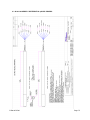
1
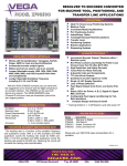
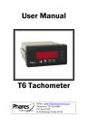
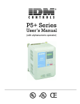
OPERATING INSTRUCTION MANUAL
MODEL P/R60 & P/R65
DIFFERENTIAL PH & ORP PROBES
N116-19 REV. 10
Water Analytics, Inc.
100 School Street
Andover, MA 01810
P/R60 & P/R65
Tel: (978) 749-9949
(855) 747-7623
Fax: (978) 749-9961
www.WaterAnalytics.net
Page 1
TABLE OF CONTENTS
1.0
GENERAL INFORMATION
4
2.0
SPECIFICATIONS
5
3.0
INSTALLATION
6
3.1 General Instructions
6
3.2 ORP 4-20 mA Probes, R65
6
3.3 Submersion Mounting Series 8 Differential Probes
6
3.4 Submersion Mounting Series 6 Differential Probes
7
3.5 Flow-through tee mounting Series 8 Differential Probes
7
3.6 Flow-through tee mounting Series 6 Differential Probes
7
3.7 Sanitary Probe P60S, P65S, R60S, R65S
7
3.8 Insertion mounting Series 4 Differential Probes
8
3.9 Hot/Wet tap insertion mounting Series 7 Differential Probes
8
4.0
8
SERVICE AND MAINTENANCE
4.1 Probe Cleaning
8
4.2 Replacement of Salt Bridge for Series 4, 6, 7 & S Differential Probes
9
4.3 Replacement of Salt Bridge for Series 8 Differential Probes
9
4.4 Storage
9
5.0
9
TROUBLESHOOTING AND SERVICE
5.1 Checking 5-wire Differential Probes P60 and R60
10
5.2 Checking Probes P65 and R65 (4-20 mA output)
11
5.3 Customer Service
12
5.4 Parts and Accessories
12
5.5 Probe Return
13
6.0
14
DRAWINGS
P/R60 & P/R65
Page 2
6.1
N106-61 SERIES 4 DIFFERENTIAL pH/ORP PROBES
14
6.2
N106-183 SERIES 6 DIFFERENTIAL pH/ORP PROBES
15
6.3
N106-184 SERIES 7 DIFFERENTIAL pH/ORP PROBES
16
6.4
N106-182 SERIES 8 DIFFERENTIAL pH/ORP PROBES
17
6.5
N106-62 SERIES S DIFFERENTIAL pH/ORP PROBES
18
6.6
N105-73 INSTALLATION OF SERIES 6 DIFFERENTIAL PROBES
19
6.7
N106-79 INSTALLATION OF SERIES 7 DIFFERENTIAL PROBES
20
6.8
N105-72 INSTALLATION OF SERIES 8 DIFFERENTIAL PROBE
21
6.9
N106-60 INSTALLATION OF SALT BRIDGE IN A DIFFERENTIAL PROBE
22
7.0
SENSOR WARRANTY
P/R60 & P/R65
ERROR! BOOKMARK NOT DEFINED.
Page 3
1.0
GENERAL INFORMATION
This manual covers all AquaMetrix P60, P65, R60 and R65 Series differential measurement pH and
ORP probes.
All mounting configurations are described.
Both those probes with encapsulated preamplifiers and those with encapsulated two-wire
transmitters are covered. If your probe has five wires it has an encapsulated preamplifier (P60 and
R60). If your probe has two wires, or in the case of an ORP probe four wires, it has an
encapsulated two-wire transmitter (P65 and R65).
The output from a two-wire transmitter type is non-isolated and un-calibrated. The system must
provide 24 Vdc, with “low” isolated from earth ground, and a means of calibrating for offset and
span.
NOTE: Do not discard the protective cap(s) that came with the sensor. If the sensor is removed
from the process for an extended period of time, thoroughly clean the sensor, put a piece of
cotton ball with few drops of water into the protective cap and replace it on the sensor. This
keeps the junction from drying out which causes slow response when put back into
operation or causes permanent damage to the sensor. Sensors should not be left in dry
lines or empty tanks for extended periods.
Do not store the sensors in a dry or humid location. When storing, check the protective
cap(s) regularly to make sure the cotton ball remains moist. Improper storage of sensors
voids the warranty.
P/R60 & P/R65
Page 4
2.0
SPECIFICATIONS
MEASURING RANGES:
pH: 0 to 14.00 pH
ORP: R60: +1999 mV
R65:
0-1000 mV / +500 mV field
selectable
PRESSURE LIMIT: 100 psig @ 65°C
40 psig @ 95°C
FLOW RATE:
10 ft./sec max. Flow should be as low as
possible in low conductivity water and in
solutions with high suspended solids
POWER SUPPLY LIMIT:
24VDC ± 4V
WETTED MATERIALS:
P60/P65: CPVC, kynar/ceramic, glass,
titanium palladium alloy and EPDM
R60/R65: CPVC, kynar/ceramic, glass,
titanium palladium alloy, EPDM, and
platinum
AUTOMATIC TEMPERATURE
COMPENSATION:
-5 to 95°C (23 to 203°F)
TRANSMISSION DISTANCE:
5-wire Probes: 900 meters (3000 ft.)
2-wire Probes: Limited only by cable
resistance and voltage of power supply
SENSITIVITY: pH: Less than 0.005 pH
ORP: Less than 0.5mV
STABILITY: 0.03 pH / 2mV per day,
non-cumulative
P/R60 & P/R65
TEMPERATURE LIMITS: -5 to 95°C
(23 to 203°F)
PROBE CABLE: 15 ft. (4.6 m)
P65C:
OUTPUT SPAN: 1.14mA / pH
OUTPUT OFFSET: 12mA @ 7pH
+1.14mA
MAX LOAD: 450 Ohms
R65C:
OUTPUT SPAN:
0-1000mV: 1.6mA / 100mV
+500mV: 1.6mA / 100mV
OUTPUT OFFSET:
0-1000mV: 12mA @ 500mV +1mA
+500mV: 12mA @ 0mV +1mA
MAX LOAD: 450 Ohms
Page 5
3.0
INSTALLATION
3.1 General Instructions
3.1.1
Specific instructions for each type of probe are given in the following pages.
Common to all probes are the following instructions:
a) If the distance between the probe and the instrument is such that a direct
connection is not possible, the probe cable should be routed to a junction box
with a terminal strip (AquaMetrix Part No. JB1). The box should be well sealed
and away from corrosion danger. Be sure that you have sufficient slack cable
to allow for probe removal for calibration and servicing.
b) Route the interconnect cable from the junction box to the instrument, preferably
in metal conduit. Do not run the power cable or control cables in the same
conduit with the probe interconnect cable.
c) Remove the protective plastic caps from the end of the probe before placing in
service.
d) For best results probes should always be mounted vertically with electrodes
down. If this is not possible, the probe must be at least 15° above horizontal.
3.2 ORP 4-20 mA Probes, R65
3.2.1
a) ORP 4-20 mA probes have four wires; black, red, green and white. The red
wire is to be connected to the +24 Vdc terminal and the back wire to the 24 Vdc
common terminal via the load in the loop.
b) For an instrument with a range of 0 to 1000 mV the green and white wires are
to be shorted.
c) For an instrument with a range of –500 to 500 mV the green and white wires
are to be isolated from each other.
3.3 Submersion Mounting Series 8 Differential Probes
Refer to Dwg# N105-72
3.3.1
a) A submersion mounting kit, STC60L is available from Water Analytics which
includes 4 ft. of 1” pipe, 1-1/2” x 1” reducer, a strain relief fitting and wire
mounting bracket. Proceed as follows, either with the kit or with your own
hardware.
b) Apply a thread sealant to the thread on the cable end of the probe and screw a
1-1/2” x 1” NPT reducer onto the probe. Route the sensor cable through an
appropriate length of 1” pipe and using thread sealant, screw the pipe into the
reducer. The cable end of the probe should not be exposed to the process. A
cable strain relief fitting should be used on the upper end of the pipe. In the kits
a wire bracket is provided to aid in supporting the assembly.
NOTE: An optional protective shroud, Part No. PROTECTOR-3 should be used on
the electrode end of the probe to protect the electrodes from accidental
contact with the tank bottom, sides or objects in the process.
P/R60 & P/R65
Page 6
3.4 Submersion Mounting Series 6 Differential Probes
Refer to Dwg# N105-73
3.4.1
a) A submersion mounting kit, STC60-6 is available from Water Analytics which
includes 4 ft. of 1” pipe, 1-1/2” x 1” reducer and a strain relief fitting. Proceed as
follows, either with the kit or with your own hardware:
b) Install the optional protective shroud, Part No. PROTECTOR-6 on the probe by
threading the probe cable through it. The shroud will contact the shoulder on
the probe.
c) Install the compression fitting components on the probe in the order shown in
the drawing below so that the pipe thread is towards the cable end of the probe.
If you are concerned that the shroud may get pushed up and expose the
electrodes you can lock it down by the positioning of the fittings.
d) Snug up the nut of the compression fitting to locate it in the desired position.
Hand tighten as much as possible, then turn 1/2 turn with a wrench.
e) Apply a thread sealant to the pipe thread portion of the compression fitting and
screw a 1-1/4” x 1” NPT reducer to it.
f)
Route the sensor cable through an appropriate length of 1” pipe and using
thread sealant, screw the pipe into the reducer on the probe. The cable end of
the probe should not be exposed to the process.
3.5 Flow-through tee mounting Series 8 Differential Probes
Refer to Dwg# N105-72
3.5.1
a) Apply pipe sealant to the electrode end of the probe and screw it into the
AquaMetrix union tee w/ adaptor (Part No. AM-MH538N9A) or any standard 11/2” NPT tee.
3.6 Flow-through tee mounting Series 6 Differential Probes
Refer to Dwg# N105-73
3.6.1
a) Take the compression fitting apart. Apply pipe sealant to the 1-1/4” NPT thread
and screw this part into a 1-1/4” tee. A larger tee with an appropriate reducer
may be used.
b) Put the compression fitting components on the probe in the order shown in the
drawing. They should be in such a position that the electrodes will be in the
pipe stream but not touching the opposite side of the tee.
c) Remove the protective cap from the probe and place the probe in the tee. Now
tighten the nut by hand as much as possible, then turn 1/2 turn with a wrench.
3.7 Sanitary Probe P60S, P65S, R60S, R65S
3.7.1
P/R60 & P/R65
The P60S is designed with a stainless steel flange to mate with a Tri-Clover ferrule
TL14AM7-2-1/2.
Page 7
3.8 Insertion mounting Series 4 Differential Probes
3.8.1
Apply pipe sealant to the electrode end of the probe and screw it into the any
standard 1-1/2” Male NPT.
3.9 Hot/Wet tap insertion mounting Series 7 Differential Probes
Refer to Dwg# N106-79
3.9.1
a) A ball valve assembly, P60-HTC, is available from Water Analytics which
includes the assembly and a safety shroud.
b) Mount the ball valve assembly in a desirable location. The assembly comes
with a field selectable, 1-1/4 NPTF or socket adaptor. Make sure valve is in the
close position before mounting.
c) Remove the union body by turning the union nut counter clockwise. Take the
compression fitting apart as shown on the drawing. Insert the back end of the
series 7 probe through the union body until safety notch on the probe aligns
with the safety stop on the union body.
d) Place the union body, with the probe attached, back into the ball vale assembly
and tighten union nut. Open ball valve & slide the probe into the process.
e) Put the compression fitting components on the probe in the order shown in the
drawing and tighten the nut by hand as much as possible, then turn 1/2 turn
with a wrench to keep probe in place.
f)
4.0
Insert protective shroud as shown.
SERVICE AND MAINTENANCE
4.1 Probe Cleaning
4.4.1
a) The probe should be kept reasonably clean to avoid measurement errors.
Frequency of cleaning can only be determined by experience. To clean
proceed as follows:
b) Rinse with clean warm water.
c) Soak the end of the probe in warm water and dish detergent for 3 or 4 minutes.
d) Brush the end of the probe, particularly the three electrodes with a soft bristle
brush such as a tooth brush. Take care not to scratch the glass electrode.
e) If the probe is still not clean, it may have to be cleaned with acid. CAUTION:
Do not acid clean probes used in processes containing cyanide solutions.
Some experimentation may be required to determine the most suitable acid for
your process. Use the most dilute acid which is effective. Normally 10 parts of
water to one part muriatic acid is sufficient. Do not use hydrofluoric acid.
f)
Soak the probe for not more than 5 minutes in the chosen acid; then rinse
thoroughly with clean warm water and soak in water for 3-5 minutes.
g) Calibrate the system in accordance with the instrument instruction manual.
P/R60 & P/R65
Page 8
4.2 Replacement of Salt Bridge for Series 4, 6, 7 & S Differential Probes
4.2.1
a) If the system cannot be calibrated after cleaning the probe, it may be necessary
to replace the standard cell solution. A kit is available from Water Analytics for
this purpose (Part No. C35-17K). Proceed as follows: Refer to DWG N106-60.
b) Hold the probe vertically with the sensor face up. Insert long nose pliers in the
blind holes in the salt bridge and turn counter-clockwise taking care not to
damage the glass electrode. Discard the used salt bridge.
c) Up-end the probe and pour out the contents of the standard electrode chamber.
Flush the chamber with a small amount of pH 7 buffer or clean water.
d) Refill the chamber with 7pH buffer solution up to the tip of the electrode inside
the chamber. DO NOT OVERFILL. It is important to leave space for the salt
bridge thread and a small amount of air.
e) Screw the new salt bridge into the cavity until finger tight. Now turn 1/4 turn
with long nose pliers. The front face of the salt bridge should be flush with the
probe face.
4.3 Replacement of Salt Bridge for Series 8 Differential Probes
4.3.1
a) If the system can’t be calibrated after cleaning the probe, it may be necessary
to replace the standard cell solution. A kit is available from Water Analytics for
this purpose (Part No. AM60-9765K). Proceed as follows: Refer to DWG N10660.
b) Hold the probe vertically electrodes up. Remove the used salt bridge using a
9/16” socket wrench, turning counter-clockwise. Discard the used salt bridge.
c) Dispose of the used solution inside the bridge chamber and flush with pH 7
solution or distilled water.
d) Refill the chamber with 7pH buffer solution, up to the tip of the electrode, inside
the chamber. DO NOT OVERFILL. It is important to leave space for the salt
bridge thread and a small amount of air.
e) Screw the new salt bridge into the cavity until finger tight. Now perform a 1/4
turn with a 9/16” socket wrench. The salt bridge edges should be flush with the
front of the probe face.
4.4 Storage
4.4.1
Do not discard the protective cap(s) that came with the sensor. If the sensor is
removed from the process for an extended period of time, thoroughly clean the
sensor, put a piece of cotton ball with few drops of water into the protective cap and
replace it on the sensor. This keeps the junction from drying out which causes slow
response when put back into operation or causes permanent damage to the sensor.
Sensors should not be left in dry lines or empty tanks for extended periods.
Do not store the sensors in a dry or humid location. When storing, check the
protective cap(s) regularly to make sure the cotton ball remains moist. Improper
storage of sensors voids the warranty.
5.0
TROUBLESHOOTING AND SERVICE
P/R60 & P/R65
Page 9
5.1 Checking 5-wire Differential Probes P60 and R60
The probe can be checked by a few simple measurements. Two pH buffer solutions, 7 pH
and either 4 pH or 10 pH, and a multimeter are required. For ORP probes two calibration
solutions, 200 and 600 mV, are required. Millivolt solutions may be ±20% of nominal value.
Actual value is noted on the bottle.
5.1.1
P60C pH probes
a) Clean the probe as described in Section 4.1. If the system cannot be
calibrated, replace the salt bridge and 7pH buffer solution as described in 4.2.
If the system still can’t be calibrated check the probe as follows:
b) Disconnect red, green, yellow and black wires at the junction box. If you are not
using a junction box, disconnect at the instrument after shutting off the power.
c) Place the probe in 7 pH buffer. Allow enough time for the temperature of the
probe and buffer to stabilize at room temperature.
d) Measure the resistance between the yellow and black wires to check the
probe’s temperature compensator. The resistance should be between 250 and
350 ohms at 25°C. If the resistance is within specifications the probes
thermistor is functioning correctly.
e) Reconnect the yellow and black wires and restore power to the instrument.
f)
Measure the voltage between the red and green wires. If it is not within –50 to
+50 millivolts with the probe in 7 pH buffer, the probe is defective. If the voltage
is OK proceed to the next step.
g) Rinse the probe and place it in 4 pH or 10 pH buffer. Allow it to stabilize then
check the voltage again between the red and green wires. If the voltage is
between 100 and 230 millivolts (negative in 10 pH buffer, positive in 4 pH
buffer) the probe is within specifications.
5.1.2
R60C ORP probes
a) Clean the probe as described in Section 4.1. If the system cannot be
calibrated, replace the salt bridge and 7pH buffer solution as described in 4.2.
If the system still can’t be calibrated check the probe as follows:
b) Disconnect red, green, yellow and black wires at the junction box. If you are not
using a junction box, disconnect at the instrument after shutting off the power.
c) Place the probe in 200 mV solution. Allow enough time for the temperature of
the probe and solution to stabilize at room temperature.
d) Measure the resistance between the yellow and black wires to check the
probe’s temperature compensator. The resistance should be between 250 and
350 ohms at 25°C. If the resistance is within specifications the probes
thermistor is functioning correctly.
e) Reconnect the yellow and black wires and restore power to the instrument.
P/R60 & P/R65
Page 10
f)
Measure the voltage between the red and green wires. The reading should be
between 160 and 240 mV; otherwise, the probe is defective. If the voltage is
OK proceed to the next step.
g) Rinse the probe and place it in 600 mV solution. Allow it to stabilize then check
the voltage again between the red and green wires. If the voltage is between
560 and 640 mV, the probe is within specifications.
5.2 Checking Probes P65 and R65 (4-20 mA output)
The operation of the 2-wire, 4-20 mA, probe can be checked by a few simple
measurements. Two pH buffer solutions, 7 pH and either 4 pH or 10 pH, and a dc
milliammeter are required.
5.2.1
P65C pH Probe
a) Disconnect the red wire at the instrument or power supply and connect it to the
milliammeter (-) black.
b) Connect the milliammeter (+) red to the instrument or power supply red wire
output terminal.
c) Rinse the probe and place it in 7 pH buffer. Allow the temperature of the buffer
and probe to stabilize at room temperature.
d) Check the offset of the probe by reading the milliammeter. The reading should
be between 11 and 13 mA. If not the probe is defective. If the offset is OK,
note the exact reading and proceed to the next step.
e) Rinse the probe and place it in 4 pH or 10 pH buffer. Allow the temperature of
the probe and buffer to stabilize at room temperature. Now check the span of
the probe by reading the milliammeter. If the probe is in 4 pH buffer, the
reading should be between 2.85 and 3.99 lower than the reading obtained in
(d).
If the probe is in 10 pH buffer, the reading should be between 2.85 and 3.99
higher than the reading obtained in (d).
If this test is not satisfied the probe is defective.
If you wish to check the temperature compensator proceed to step (f).
If the span of the probe drops below 2.85mA than the probe still can be used
adjustments will have to be made to the receiving device to compensate for the
low span.
f)
P/R60 & P/R65
To check the operation of the temperature sensor in the probe, heat the buffer
used in step (e) with the probe in it to about 50°C. The milliammeter reading
should be within ±0.15 mA of the reading observed in step (e).
Page 11
5.2.2
ORP Probes R65
a) Disconnect the red wire at the instrument or power supply and connect it to the
milliammeter (-) black. Connect the milliammeter (+) red to the instrument or
power supply red wire output terminal.
b) For a probe with range of –500 to 500 mV: (white and green wire open). Rinse
the probe and place it in the 200 mV solution. The milliammeter should read
between 14.4 and 16.0 mA.
Rinse the probe and place it in the 600 mV solution. The meter should read
between 19.55 and 20.45 mA.
c) For a probe with range of 0 to 1000 mV: (white and green wire joined). Rinse
the probe and place it in the 200 mV solution. The milliammeter should read
between 6.4 and 8.0 mA.
Rinse the probe and place it in the 600 mV solution. The meter should read
between 12.8 and 14.4ma.
5.3 Customer Service
5.3.1
If a problem has not been resolved with the above procedures, a telephone
consultation with your AquaMetrix representative, or directly with Water Analytics
will provide the answer.
Water Analytics Inc.
100 School Street
Newmarket, Ontario
Tel: (888) 749-9099
Tel: (978) 749-9949
Toll Free: (855) 747-7623
Fax: (978) 978-9961
Email: [email protected]
5.4 Parts and Accessories
Description
Submersion Mounting Kit for Series –8 Probes
Submersion Mounting Kit for Series –6 Probes
Protective shroud for Series –8 Probes
Protective shroud for Series –6 Probes
Hot/Wet tap Ball Valve Assembly for Series –7
Union Mounting Tee w/ Adaptor for Series –8
500 mL pH 7 Buffer Solution
4L pH 7 Buffer Solution
500 mL pH 4 Buffer Solution
4L pH 4 Buffer Solution
500 mL pH 10 Buffer Solution
4L pH 10 Buffer Solution
500 mL 200mV Buffer Solution
4L 200mV Buffer Solution
500 mL 600mV Buffer Soltion
4L 600mV Buffer Solution
Salt bridge kit for Series –4, –6, –7 & –S
(Package of 3, incl. salt bridge and cell solution)
Salt bridge kit for Series –8
(Package of 3, incl. salt bridge and cell solution)
Junction box with terminal strip
50 ft. 5-wire Interconnect cable dressed both ends
P/R60 & P/R65
Part #
STC60L
STC60-6
PROTECTOR-3
PROTECTOR-6
P60-HTC
AM-MH538N9A
A35-14
A35-118
A35-13
A35-117
A35-24
A35-119
A35-40
A35-115
A35-41
A35-116
C35-17(K)
AM60-9765(K)
JB-1
C42-5P-050
Page 12
5.5 Probe Return
5.5.1
If you are returning a probe for inspection, enclose description of the problem. Pack
the probe adequately to avoid damage to the glass electrode and ensure that it will
not be exposed to temperatures below –5°C. Water Analytics cannot be
responsible for shipping damage nor for damage due to frozen electrodes.
For safety reasons, Water Analytics cannot accept probes which have not been
thoroughly cleaned to remove all process material.
P/R60 & P/R65
Page 13
6.0
DRAWINGS
6.1 N106-61 SERIES 4 DIFFERENTIAL pH/ORP PROBES
P/R60 & P/R65
Page 14
6.2 N106-183 SERIES 6 DIFFERENTIAL pH/ORP PROBES
P/R60 & P/R65
Page 15
6.3 N106-184 SERIES 7 DIFFERENTIAL pH/ORP PROBES
P/R60 & P/R65
Page 16
6.4 N106-182 SERIES 8 DIFFERENTIAL pH/ORP PROBES
P/R60 & P/R65
Page 17
6.5 N106-62 SERIES S DIFFERENTIAL pH/ORP PROBES
P/R60 & P/R65
Page 18
6.6 N105-73 INSTALLATION OF SERIES 6 DIFFERENTIAL PROBES
P/R60 & P/R65
Page 19
6.7 N106-79 INSTALLATION OF SERIES 7 DIFFERENTIAL PROBES
P/R60 & P/R65
Page 20
6.8 N105-72 INSTALLATION OF SERIES 8 DIFFERENTIAL PROBE
P/R60 & P/R65
Page 21
6.9 N106-60 INSTALLATION OF SALT BRIDGE IN A DIFFERENTIAL PROBE
P/R60 & P/R65
Page 22