1
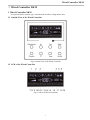
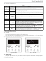
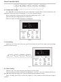
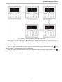
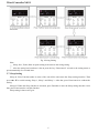
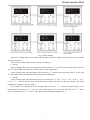
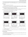
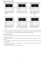
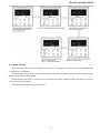
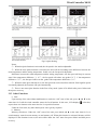
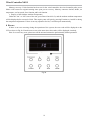
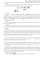
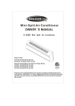
USER'S MANUAL
MULTI COMBI SERIES
FLOOR&CEILING MC-F09,12,18,24AI
User Notice
◆ When operating, the entire capacity of the cooperating indoor unit should be not larger than
150% of outdoor unit. Otherwise, it will cause the shortage of cooling (heating) capacity.
◆ The power supply of the entire unit must be the power supply of outdoor unit. And
disconnect the main power of outdoor units before cleaning.
◆ In order to turn on the units successfully, the main power switch should be opened 8 hours
before the operation.
◆ After receiving the turn off signal, every indoor unit will continue to work for 20-70sec to
make use of the rest cool air or the rest heat air in the heat exchanger, while preparing for the next
operation. And this is normal.
◆ When the selected operating mode of the indoor unit are clash with the operating mode of
the outdoor unit, the malfunction light will blink after 5s on the indoor unit or remote controller
showing that the operation clash, then the indoor unit will stop. At this time, change the operation
mode of the indoor unit to the one that would not clash with the outdoor operating mode to make
the operation normal. The cooling mode is not clash with the dry mode, while the fan mode is not
clash with any mode.
◆ The appliance shall not be installed in the laundry .The appliance shall not be used by
children without supervisor.
◆ An all-pole disconnection switch having a contact separation of at least 3mm in all poles
should be connected in fixed wiring.
◆ Missing information regarding electric supply tolerances(+/-10%, +/-1Hz) in
documentation.
◆ Humidity range: 30%~95%.
◆ Main switch provided by end user: main switch handle should be black or gray, it can be
locked in “OFF” position with padlock.
◆ The main disconnection device should be installed at a height of 0.6~1.7m. over current
protection is required(EN 60947-3, EN 60947-2).
◆ The cooling range of the unit is the outdoor environment temp.-5~48 ℃ DB, the heating
range of the unit( only for the heat pump type unit) is the outdoor environment temp. -15~27 ℃
DB.
This product must not be disposed together with the domestic waste. This product
has to be disposed at an authorized place for recycling of electrical and electronic
appliances.
Thank you for your selecting of Sinclair air conditioner, please read this usage and install
instruction carefully and keep it well in order to use this unit correctly.
Wired Controller XK19
Ⅰ Wired Controller XK19
1 Wired Controller XK19
It is optional for the cassette type, wall-mounted, and floor ceiling indoor units.
1.1 Outside View of the Wired Controller
Fig.1 Outside View of the Wired Controller
1.2 LCD of the Wired Controller
Fig.2 LCD of the Wired Controller
1
Wired Controller XK19
1.3 Introduction to the Symbols on LCD
Table 1
No.
Symbols
Description
1
Swing function.
2
Sleep function (3 types: sleep 1,sleep2 and sleep 3).
3
Running modes of the indoor unit (Cooling, Dry, Fan and Heating).
4
Defrosting function for the outdoor unit.
5
Gate-control function (this function is yet unavailable for this unit).
6
Lock function.
7
High, middle, low or auto fan speed of the indoor unit.
8
SHIELD
Shield functions (buttons, temperature, On/Off, Mode or Save is shielded or
Save is shielded by the remote monitor.
9
TURBO
Turbo function.
10
MEMORY
Memory function (The indoor unit resumes the original setting state after
power failure and then power recovery).
11
MASTER
Master wired controller (this function is yet unavailable for this unit).
It blinks under on state of the unit without operation of any button.
12
13
SAVE
Energy-saving function.
Ambient/preset temperature value.
14
15
E-HEATER
16
BLOW
Electric auxiliary heating function.
Blow function.
Timing value.
17
18
QUITE
Quiet function (two types: quiet and auto quiet).
19
SET
It will be displayed under the debugging mode.
2 Buttons
2.1 Buttons on the Wired Controller
Fig. 3 Buttons on the Wired Controller
2
Wired Controller XK19
2.2 Function of the Buttons
Table 2
No.
Name
1
Enter/cancel
2
▲
6
▼
3
Fan
4
Mode
5
Function
Function
① Function selection and cancellation.
② Press it for 5s to examine the outdoor ambient temperature.
① Running temperature setting of the indoor unit, range:16 ~ 30℃ .
② Timer setting, range:0.5-24 hr.
③ Switchover between quiet/auto quiet or among sleep1/sleep2/sleep 3.
Setting of the high/middle/low/auto fan speed.
Setting of the Cooling/Heating/Fan/Dry mode of the indoor unit.
Switchover among the functions of Swing/Sleep/Turbo/Save/E-heater/Blow /
Quiet etc.
7
Timer
Timer setting.
8
On/Off
Turn on/off the indoor unit.
4+2
▲+Mode
3 +6
Fan+▼
2 +6
▲+▼
Press them for 5s under off state of the unit to enter/cancel the Memory function
(If memory is set, indoor unit after power failure and then power recovery will
resume the original setting state. If not, the indoor unit is defaulted to be off after
power recovery. Memory off is default before delivery.).
By pressing them at the same time under off state of the unit, will be displayed
will be displayed on
on the wired controller for the cooling only unit, while
the wired controller for the cooling and heating unit.
Upon startup of the unit without malfunction or under off state of the unit,press
them at the same time for 5s to enter the lock state, in which case, any other
buttons won’t respond the press. Repress them for 5s to quit this state.
3 Operation Instructions
3.1 On/Off
Press On/Off to turn on the unit and turn it off by another press.
Note: The state shown in Fig.4 indicates the “Off” state of the unit after power on. The state shown in
Fig.5 indicates the “On” state of the unit after power on.
Fig. 4 “Off” State
Fig. 5 “On” State
3.2 Mode Setting
Under the “On” state of the unit, press Mode to switch the operation modes as the following sequence:
Cooling-Dry-Fan-Heating.
3
Wired Controller XK19
3.3 Temperature Setting
Press ▲or ▼ to increase/decrease the preset temperature. If press either of them continuously, the
temperature will be increased or decreased by 1℃ every 0.5s,as shown in Fig.6.
In the Cooling, Dry or Heating mode, the temperature setting range is 16℃~ 30℃ .
In the Fan mode, the setting temperature is fixed at 26℃ .
In the Auto mode, the setting temperature is unadjustable.
Fig.6
3.4 Fan Setting
Under the “On”/”Off” state of the unit, press Fan and then fan speed of the indoor unit will change
circularly as shown in Fig.7.
Auto
Low
Middle
High
Fig.7
3.5 Timer Setting
Under the “On”/”Off” state of the unit, press Timer to set timer off/on.
Timer on setting: press Timer, and then LCD will display “xx.x hour”, with “hour” blinking. In this case,
press ▲or ▼ to adjust the timing value. Then press Enter/cancel to confirm the setting.
Timer off setting: press Timer, if LCD won’t display xx.x hour, and then it means the timer setting is
canceled.
4
Wired Controller XK19
Timer off setting under the “On” state of the unit is shown as Fig.8.
Fig. 8 Timer off Setting under the “On” State of the Unit
Timer range: 0.5-24hr. Every press of ▲or ▼ will make the set time increased or decreased by 0.5hr. If
either of them is pressed continuously, the set time will increase/ decrease by 0.5hr every 0.5s.
3.6 Swing Setting
Swing On: Press Function under on state of the unit to activate the swing function. In this case,
blink. After that, press Enter/cancel to make a confirmation.
Swing Off: When the Swing function is on, press Function to enter the Swing setting interface, with
blinking. After that, press Enter/cancel to cancel this function.
Swing setting is shown as Fig.9.
5
will
Wired Controller XK19
Fig. 9 Swing Setting
Note:
① .Sleep, Save, Turbo, Blow or Quiet setting is the same as the Swing setting.
② .After the setting has been done, it has to press the key “Enter/cancel” to back to the setting status or
quit automatically five seconds later.
3.7 Sleep Setting
Sleep on: Press Function under on state of the unit till the unit enters the Sleep setting interface. Then
press ▲or ▼ to switch among Sleep 1, Sleep 2 and Sleep 3. After that, press Enter/cancel to confirm the
setting.
Sleep off: When the Sleep function is activated, press Function to enter the Sleep setting interface. After
that, press Enter/cancel to can this function.
Sleep setting is shown as Fig.10.
6
Wired Controller XK19
Fig. 10 Sleep Setting
Sleep off is default after power failure and then power recovery, and the sleep functions is unavailable
under the fan mode.
There are three Sleep modes: Sleep 1, Sleep 2 and Sleep 3.
a. Sleep 1
In the Cooling or Dry mode, the temperature will increase by 1℃ after the unit runs under Sleep 1 for 1hr
and 1℃ after another 1hr.After that, the unit will run at this temperature.
In the Heating mode, the temperature will decrease by 1℃ after the unit runs under Sleep 1 for 1hr and
1℃ after another 1hr. After that, the unit will run at this temperature.
b. Sleep 2
In the Cooling mode, the temperature may be set between 16 ℃ -23 ℃ , 24 ℃ - 27 ℃ or 28 ℃ - 29 ℃
or at 30 ℃ , and their Sleep curves are shown in Fig.11 (Note: The curve is only for reference, the actual
temperature is subject to the time point.).
For example: The temperature in the Cooling mode is set at 25 ℃ . Under the mode of Sleep 2, the
temperature will increase by 1℃ every 1hr. After it increases by 2℃ in total, it will keep at 27℃ . 7 hours
later, it will decrease by1℃ , i.e. 26℃ .After that, the unit will keep running at 26℃ .
7
Wired Controller XK19
(
T
e
m
p
/
)
℃
31
30
29
28
27
26
25
24
23
22
21
20
19
18
17
16
0
1
2
3
4
5
6
7
8
9
10
11
12
Time/(Hr)
Fig.11 Sleep Curve of Sleep 2 in Cooling Mode
In the Heating mode, the temperature may be set at 16℃ or between 17℃ - 20℃ , 21℃ -27℃ or 28℃ 30℃ and their Sleep curves are shown in Fig.12:
(
T
e
m
p
/
)
℃
31
30
29
28
27
26
25
24
23
22
21
20
19
18
17
16
0
1
2
3
4
5
6
7
8
9
10
11
12
T i m e /(H r )
Fig.12 Sleep Curve of Sleep 2 in Heating Mode
8
Wired Controller XK19
For example, the temperature in the Heating mode is set at 22 ℃ .Under the mode of Sleep2, the
temperature will decrease by 1 ℃ every 1hr. After it decreases by 2 ℃ in total, i.e. 20 ℃ ,the unit will keep
running at 20℃ .
c. Sleep 3
Sleep curve setting under Sleep 3(DIY mode)
d. Under the mode of Sleep 3, press Timer to enter the Sleep setting. In this case, “1 HOUR” is displayed
where the timing value once is displayed and the corresponding temperature with the last Sleep curve setting
is displayed where the ambient/preset temperature once in displayed.
e. Press ▲or ▼ to change the corresponding temperature setting.
f. Press Timer, time will automatically increase by 1hr, and the corresponding temperature with the last
Sleep curve setting is displayed where the ambient/preset temperature once is displayed.
g. Repeat step 2 and step 3 till 8 HOUR Sleep setting is finished.
h. Press Enter/cancel to confirm the setting.
Sleep curve setting under Sleep 3 is as shown in Fig.13.
Fig. 13 Sleep Curve Setting under Sleep 3
Notes:
① .During the above setting, if Function is pressed down or there is not any operation within 5s, sleep
curve setting will be canceled.
② .26℃ is the default Sleep curve temperature before delivery. The wired controller will automatically
memorize the Sleep curve after the setting.
3.8 Turbo Setting
Turbo function: The unit at the high fan speed can realize quick cooling or heating so that the room
temperature can quickly approach the setting value.
In the Cooling or Heating mode, press Function till the unit enters the Turbo setting interface and then
press Enter/Cancel to confirm the setting.
9
Wired Controller XK19
When the Turbo function is activated, press Function to enter the Turbo setting interface and then press
Enter/Cancel to cancel this function.
Turbo function setting is as shown in Fig.14.
Fig.14 Turbo Setting
Notes:
① .When the Turbo function is activated, if the difference between the room temperature and set
temperature is at or below 2 ℃ (detected in successive 1 min.), the Turbo function will be automatically
deactivated.
② .Turbo function is unavailable in the Dry and Fan mode. And the Turbo function is off after power
failure and then power recovery. If Quiet function is on, Turbo function will be canceled subsequently.
3.9 Save Setting
Save: Energy saving which will result the air conditioner runs in smaller temperature range is realized by
setting lower limited value in the Cooling or Dry mode and upper limited value in the Heating mode.
Save Setting for Cooling:
Under the “On” state and in the Cooling or Dry mode of the unit, press Function to enter the Save setting
interface and then press ▲or ▼ to adjust the lower limited value in the Cooling mode. After that, press Enter/
Cancel to activate the Save function. The initial lower limited value in the Cooling mode is 26℃ .
When the Save function is activated, press Function to enter the Save setting interface and then press
Enter/cancel to cancel this function.
The Save setting for cooling is shown in the Fig.15
10
Wired Controller XK19
Fig. 15 Saving Setting for Cooling
Save Setting for Heating:
Under on state or in the Heating mode of the unit, press Function to enter the Save setting interface and
then press ▲or ▼ to adjust upper limited value in the Heating mode. After that, press Enter/Cancel to activate
the Save function for heating. The upper initial limited value in the Heating mode is 20℃ .
After the Saving function is activated, press Function to enter the Save setting interface and then press
Enter/Cancel to cancel this function.
Save setting for heating is as shown in Fig. 16
11
Wired Controller XK19
Fig.16 Save Setting for Heating
Notes:
① .If press Function on the Save setting interface or if there is not any operation for 5s after last button
press, the Save setting will be canceled automatically by the system, with memorizing the present setting data.
② .When power is on after the power failure, the Save function will be memorized.
3.10 E-heater Setting
E-heater (auxiliary electric heating function): In the Heating mode, E-heater is allowed to be turned on for
improvement of efficiency.
Once the wired controller or the remote controller enters the Heating mode, this function will be turned on
automatically.
Press Function in the Heating mode to enter the E-heater setting interface and then press Enter/cancel to
cancel this function.
Press Function to enter the E-heater setting interface, if the E-heater function is not activated, and then
press Enter/Cancel to turn it on.
The setting of this function is shown as Fig.17 below:
12
Wired Controller XK19
Fig.17 E-heater Setting
3.11 Blow Setting
Blow function: After the unit is turned off, the water in evaporator of indoor unit will be automatically
evaporated to avoid mildew.
In the Cooling or Dry mode, press Function till the unit enters the Blow setting interface and then press
Enter/Cancel to active this function.
When the Blow function is activated, press Function to the Blow setting interface and then press Enter/
Cancel to cancel this function.
Blow function setting is as shown in Fig.18
13
Wired Controller XK19
Fig.18 Blow Setting
Notes:
① .When the Blow function is activated, if turning off the unit by pressing On/Off or by the remote
controller, the indoor fan will run at the low fan speed for 10 min, with “BLOW” displayed on the LCD.
While, if the Blow function is deactivated, the indoor fan will be turned off directly.
② .Blow function is unavailable in the Fan or Heating mode.
3.12 Quiet Setting
Quiet function consists of two kinds: quiet and auto quiet.
Press Function till the unit enters the Quite setting interface, with “Quiet” or “Auto” blinking. In this case,
press ▲or ▼ to switch between Quiet and Auto and then press Enter/cancel to make a confirmation.
When the Quiet function is activated, press Function till the unit enters the Quite setting interface, with
“Quite” or “Auto” blinking. Then press Enter/cancel to cancel this function.
Quiet function setting is as shown in Fig.3.16:
14
Wired Controller XK19
Fig.19 Quiet Setting
Notes:
① .When the Quite function is activated, the fan speed is low and un-adjustable.
② .When the Auto Quite function is activated, the unit will run according to the difference between the
room temperature and the setting temperature. In this case, the fan speed is adjustable.
Difference between the room temperature and the setting temperature: the fan speed will keep its current
state if the temperature difference ≥ 4 ℃ ; the fan speed will reduce one grade if 2 ℃ ≤ the temperature
difference ≤ 3℃ ; the fan speed will be at min. grade if the temperature difference ≤ 1℃ .
③ .When the Auto Quiet function is on, the fan speed can not be raised but reduced. If the high fan speed
is manually adjusted, the function will quit automatically.
④ .There is not Auto Quiet function in the Fan or Dry mode. Quiet off is default after power failure and
then power recovery.
3.13 Other Functions
a. Lock
Upon startup of the unit without malfunction or under the “Off” state of the unit, press ▲ and ▼ at the
same time for 5s till the wired controller enters the Lock function. In this case, LCD displays . After that,
repress these two buttons at the same time for 5s to quit this function.
Under the Lock state, any other button press won’t get any response.
b. Memory
Memory switchover: Under the “Off” state of the unit, press Mode and ▲ at the same time for 5s to
switch memory states between memory on and memory off. When this function is activated, Memory will be
displayed. If this function is not set, the unit will be under the “Off” state after power failure and then power
recovery.
15
Wired Controller XK19
Memory recovery: If this function has been set for the wired controller, the wired controller after power
failure will resume its original running state upon power recovery. Memory contents: On/Off, Mode, set
temperature, set fan speed, Save function and Lock function.
c. Enquiry of the Outdoor Ambient Temperature
Under the “On” or “Off” state of the unit, press Enter/Cancel for 5s, and the outdoor ambient temperature
will be displayed after a sound of click. This enquiry state will quit by pressing Function or On/Off or during
the temperature adjustment. If there is not any operation for 10s, it will also quit automatically.
4 Errors
If there is an error occurring during the operation of the system, the error code will be displayed on the
LCD, as show in Fig.20. If multi errors occur at the same time, their codes will be displayed circularly.
Note: In event of any error, please turn off the unit and contact the professionally skilled personnel.
Fig.20
16
Wired Controller XK19
Table 3 Meaning of Each Error
Error Code
Error
High pressure protection
E1
Low pressure protection
E3
Discharge protection
E4
Over-current protection
P5
Communication error
E6
Indoor water overflow protection
E9
Mode conflict
E7
Anti-freezing protection
E2
Defrosting or oil returning for heating
H1
Indoor ambient temperature sensor open/short circuit
F1
Evaporator temperature sensor open/short circuit
F2
Indoor unit (liquid valve) refrigerant pipe inlet temperature sensor error
b5
Indoor unit (gas valve) refrigerant pipe outlet temperature sensor error
b7
Condenser coil inlet temperature sensor open/short circuit
A5
Condenser coil midway temperature sensor error
F4
Condenser coil outlet temperature senor open/short circuit
A7
Discharge air temperature sensor error
F5
Outdoor ambient temperature sensor error
F3
Module temperature sensor error
oE
Outdoor unit overall error
oE
17
Wireless Remote Controller YT1F
Ⅱ Wireless Remote Controller YT1F
Notes:
① .Be sure that there are no obstructions between the receiver and the remote controller;
② .Do not drop or throw the remote controller;
③ .Do not let any liquid into the remote controller and expose the remote controller to direct sunlight or
any place where is very hot.
④ .T his is a general use remote controller. If press some button which is not available for the
corresponding function, the unit will keep the original running status.
1 Function of Press Buttons:
Note: This remote controller is universal and can be used for multi‐functional air conditioning. If the button on the remote controller with the function which the air conditioner doesn’t have is pressed, the unit remains in its original operating mode.
Fig.21
1) ON/OFF ( )
Press this button to turn on/off the unit. After that, the sleep function will be canceled but the preset time
is still remained.
2) MODE
Auto, Cool, Dry Fan, Heat modes can be selected circularly by pressing this button. Auto mode is the
default after power on. Under Auto mode, the temperature will not be displayed. Under Heat mode, the initial
value is 28℃ (82 ℉ ); Under other modes, the initial value is 25℃ (77 ℉ ).
3) SLEEP
Sleep On and Sleep Off can be selected by pressing this button. After powered on, the default is Sleep Off.
After the unit is turned off, the Sleep function is canceled. When the sleep function is set already, the symbol
will be displayed. And at this time, the time of timer can be adjusted. Under Fan and Auto modes, this
unction is not available.
18
Wireless Remote Controller YT1F
4) FAN
Auto, Low, Middle, or High fan speed can circularly selected by pressing this button. After powered on,
the default is Auto speed. Under Dehumidifying mode, only Low fan speed is available.
5) CLOCK
The clock can be set up by pressing this button, with the symbol
displayed and blinking. In such a
case, pressing + or - within 5 seconds can adjust the value. If the button is pressed down for more than 2
seconds, the value on ten’s place will increase by 1 in every 0.5 seconds. After that, repressing this button
and then symbol
stops blinking, which indicates the setting is made successfully. After powered on, the
default value is 12:00 with
displayed. Once the symbol
is displayed, the current time is the Clock value;
otherwise it is the Timer value.
6) LIGHT
Light On and Light Off can be set by pressing this button when the unit is at On or Off status. After
powered on, the default is Light On.
7) TURBO
In Cool or Heat mode, pressing this button can activate or deactivate this function. When this function
is on, its symbol will be displayed. Any change of either mode or fan speed will make this function canceled
automatically.
8) BLOW
BlOW On and BLOW Off can be set by pressing this button. In Cool and Dehumidifying modes, press
this button to activate this function and then “BLOW” will be displayed. After that, it can be canceled by
repressing this button. After powered on, the default is Blow Off. If the ON/OFF button is operated or the unit
is switched to the Cool or Dehumidifying mode, it will keep its original status. When the unit is turned off,
Only Blow Off is available. Under Auto, Fan or Heat mode, this function is unavailable.
9) -
The preset temperature can be decreased by pressing this button. If the button is pressed down for more
than 2 seconds, the temperature will be decreased quickly until it is released, with ℃ ( ℉ ) displayed al the
time. Under Auto mode, the temperature adjustment is unavailable.
10) +
The preset temperature can be increased by pressing this button. If the button is pressed down for more
than 2 seconds, the temperature will be increased quickly until it is released, with ℃ ( ℉ ) displayed all the
time. Under Auto mode, the temperature adjustment is unavailable. The setting range is 16-30 ℃ or 61-86 ℉
11) TEMP
It can be decided by pressing this button which temperature will be displayed, indoor set temperature, or
indoor ambient temperature. When the indoor unit is powered on, the indoor set temperature will be displayed,
, the indoor ambient temperature will be displayed. However, the indoor
while if the status is changed to
set temperature will be displayed again when the controller receives other remote controls signals. Without
setting this function, the default is the indoor set temperature.
12) SWING UP/DOWN ( )
The swing angle which circularly changes as below can be selected by pressing this button:
19
Wireless Remote Controller YT1F
This kind of remoter controller is universal. And the three swing statuses of
are the same
as that of
.
If the swing function is deactivated when the air guide louver is swing up and down, it will stop at the
current position.
indicates that the air guide louver swings up and down among all five positions.
13) AIR ( )
AIR ON or Air OFF can be selected by pressing this button.
14) TIMER ON
“ON” will be displayed and blink for 5 seconds by pressing this button, and soon adjust the time by
pressing + or - within 5 seconds. Each press will make the time increased or decreased by 1 minute. If
the button is pressed down for more than 2 seconds, the time will be changed quickly in such a way: firstly
the value on the one’s place is changed and then is the value on the ten’s place. Once Timer ON has been set
already, it can be canceled by repressing it. Before the setting, please adjust the CLOCK to the current actual
time.
15) TIMER OFF
TIME OFF can be activated by pressing this button, with “OFF” blinking. The method of setting is the
same as that for TIMER ON.
)
16) HEALTH (
This function can be activated or deactivated by pressing this button. After the unit is turned on, the
default is HEALTH ON.
17) I FEEL
This function can be activated by pressing this button and canceled by another press. When this function
is on, the I FEEL information will be sent out in 200ms after each operation on the controller and the remote
controller will send the temperature information to the main controller every 10 minutes.
2 Guide for General Operation
a. After powered on, press ON/OFF and then the unit will start to run. (Note: when powered off, the
guide louver of the main unit will close automatically).
b. Press MODE to select the desired running mode.
c. Press + or - to set the desired temperature (it is unnecessary to set the temperature under the AUTO
mode.)
d. Press FAN to set the fan speed, AUTO, LOW, MID, or HIGH.
e. Press
to select the swing angle.
3 Guide for Optional Operation
a. About BLOW
This function indicates that moisture in the evaporator of the indoor unit will be dried after the unit is
stopped to avoid mould.
① .BLOW ON: When press the ON/OFF button to turn off the unit, the indoor fan will continue running
for about another 10 minutes at the low speed. In this case, the indoor fan can be stopped directly by pressing
the button BLOW.
20
Wireless Remote Controller YT1F
② .BLOW OFF: When press the ON/OFF button to turn off the unit, the whole unit will be stopped
completely.
b. About AFTERHEAT BLOW
Under the Heat mode or Auto Heat mode, if the unit is turned off, the compressor and outdoor fan will
stop running immediately and the upper and lower guide board will rotate to the horizontal position, while the
indoor fan will still run at the low fan speed. Then, 10 seconds later, the unit will stop completely.
c. About AUTO RUN
When AUTO RUN is selected, the setting temperature will not be displayed on the LCD and the unit will
choose the suitable running mode automatically in accordance with the room temperature.
d. About TURBO
If this function is activated, the unit will run at super-high fan speed to cool or heat quickly so that the
ambient temperature will approaches the preset temperature as soon as possible.
21
Contents
Ⅰ Safety Information............................................................................................... 1
Ⅱ Selection of Installation Location and Precautions.............................................. 2
1 Selection of Installation Location for Air Conditioner Unit.......................................... 2
2 Selection of Installation Location.................................................................................. 2
3 Caution for installation where air conditioner trouble is likely to occur....................... 2
Ⅲ Installation of Floor And Ceiling Type Indoor Unit............................................ 3
1 Space dimension for installation of the unit.................................................................. 3
2 Important notice............................................................................................................. 3
3 There are 2 styles of installation.................................................................................... 3
4 Electrical wiring............................................................................................................ 6
5 Install the drainage pipe................................................................................................. 7
6 Install the connection pipes........................................................................................... 8
Ⅳ Constitutes and Names of Every Part of Floor And Ceiling Type Indoor Unit... 9
Ⅴ Working Temperature Range............................................................................. 10
Ⅵ Maintenance Method......................................................................................... 11
1 Cleaning the air filters.................................................................................................. 11
2 Cleaning the unit.......................................................................................................... 11
3 At the start of the season.............................................................................................. 11
4 During the off season.................................................................................................... 11
Ⅶ Operating Instructions . ..................................................................................... 12
Ⅷ Malfunction Analyzing...................................................................................... 14
1 Service center............................................................................................................... 14
2 After-sales Service........................................................................................................ 14
Ⅰ Safety Information
Please read this manual carefully before use this unit, and operate it correctly according to the guide in
this manual.
Please take specially note to the meaning of these two marks:
Warning! This mark means that it may cause casualty or badly hurt if the operation is incorrect.
Caution! This mark means that it may cause casualty or property loss if the operation is incorrect.
Warning!
◆ For the usage safety of the air conditioner, the units should be earthed reliably .Do not connect the earth
line with the gas pipe, water pipe, drainage pipe or other places that specialized personnel considers unsafe.
◆ Air conditioner must use special power supply circuit and switches for creepage protect and air with
enough capacity should be installed in the circuit.
◆ Ensure that the connecting of power cord is normal, otherwise, electric shock or fire may happened.
◆ Do not cut off the power supply to turn off the unit when it is running, otherwise life time of units may
shortened.
◆ Do not mangle wire or adopts wires that are not recommend to use, otherwise, electric shock or fire
may happened.
◆ Please don’t operate the unit by wet hand, or electric shock may happened.
◆ Don’t insert finger or stick like things into outlet vent, otherwise, damage may be happened.
◆ Cut down the main power switch immediately if malfunction (such as smell the burning odor etc.)
happen, and then contact the special engaged maintenance center. If the abnormal state is maintained, the unit
may be damaged or electric shock or fire may be happened.
◆ Do not refit the conditioner. Please contact the agency or professional personnel to repair or move the
conditioner.
◆ Do not adopt fuse with unsuitable capacity or adopt iron thread instead of fuse, otherwise malfunction
or fire may happened.
◆ Do cut off the main power supply of air conditioner if it would not be used for a long time.
◆ Please turn off the main power of the whole unit before cleaning the conditioner, otherwise electric
shock or harm may be happened.
◆ Chemical sprayer should be placed 1m or more away from the unit, otherwise fire or explode may be
caused.
◆ Do not let blockage happened in the inlet or outlet vent of the air conditioner, this would cause low
efficacy or unit stop.
1
Ⅱ Selection of Installation Location and Precautions
1 Selection of Installation Location for Air Conditioner Unit
The installation of air conditioner unit must be in accordance with national and local safety
codes.
Installation quality will directly affect the normal use of air conditioner unit. The user is
prohibited from installation by himself. Please contact your dealer after buying this machine.
Professional installation workers will provide installation and test services according to
installation manual.
Do not connect to power until all installation work is completed.
2 Selection of Installation Location
* Such a place where cool air can be distributed throughout the room.
* Such a place where is condensation water is easily drained out.
* Such a place that can handle the weight of indoor unit.
* Such a place, which has easy access for maintenance.
* Such a place where is permitting easy connection with the outdoor unit.
* Such a place where is 1m or more away from other electric appliances such as television, audio device,
etc.
* Avoid a location where there is heat source, high humidity or inflammable gas.
* Do not use the unit in the immediate surroundings of a laundry, a bath, a shower or a swimming pool.
* Be sure that the installation conforms to the installation dimension diagram.
3 Caution for installation where air conditioner trouble is likely to occur
* Where there is too much of oil.
* Where it is acid base area.
* Where there is irregular electrical supply.
2
Ⅲ Installation of Floor And Ceiling Type Indoor Unit
1 Space dimension for installation of the unit
The space around the unit is adequate for ventilation. (Refer to Fig.1)
Fig.1
2 Important notice
a. The unit must be installed by the professional personnel according to this install instruction to ensure
the well use.
Please contact the local NEPA spol.s.r.o special nominated repair department before installation.
Any malfunction caused by the unit that is installed by the department that is not special nominated by NEPA
would not deal with on time by the inconvenience of the business contact.
b. It should be done by professional personnel when the air conditioner unit is moved to other place.
3 There are 2 styles of installation
* Ceiling type
* Floor type
Each type is similar to the other as follows:
a. Determine the mounting position on ceiling or wall by using paper pattern to indicate indoor frame.
Mark the pattern and pull out the paper pattern.(Refer to Fig.2)
b. Remove the return grill, the side panel and the hanger bracket from the indoor unit as per procedure
bellow.
* Press the fixing knob of the air intake grills, the grilles will be opened wider and then pull them out
from the indoor.
* Remove the side panel fixing screw and pull to the front direction (arrow direction) to remove. Side
panel fixing screw. (Refer to Fig.3)
3
* Loosen two hanger bracket setting bolts (M8) on eath side for less than 10mm. Remove two hanger
bracket fixing bolts (M6) on the rear side. Detach the hanger bracker by pulling it backward (Refer to Fig.5).
Fig.2
Fig.3
c. Set the suspension bolt. (Use W3/8 or M10 size suspension bolts)
* Adjust the distance from the unit to the ceiling slab beforehand. (Refer to Fig.4)
d. Fix the hanger bracket to the suspension bolt.
Warning !
* Make sure that extended suspension bolt from the ceiling stays inside the arrowed position. Readjust
the hanger bracket when it is outside the arrowed position. (Refer to Fig.6)
* Suspension bolt stays inside the cap of indoor unit. Never remove the cap.
e. Lift the unit and slide forward unit the dent. (Refer to Fig.7)
f. Screw tightly both hanger bracket-setting bolts (M8). (Refer to Fig.5)
g. Screw tightly both hanger bracket-fixing bolts (M6) to prevent the movement of the indoor unit. (Refer
to Fig.5)
h. Adjust the height so that rear side of the drainpipe slightly inclines to improve drainage.
Caution !
* Adjust the height by turning the nut with a spanner.
* Insert the spanner from the hanger bracket opening. (Refer to Fig.8)
In case of hanging
It is possible to install using inward facing hanger brackets by not removing the brackets from the indoor
unit. (Refer to Fig.9)
Be sure to use only the specified accessories and parts for installation work.
4
Celling
Hanger bracket
40 or less
Hanger bracket
setting bolt(M8)
Suspension bolt
Hanger bracket
fixing bolt(M6)
Hanger bracket
Fig.4
Fig.5
Celling slab
BOLT POSITION
INWARD
Hanger bracket
Fig.7
Fig.6
Fig.8
Fig.9
When installing the indoor unit, you can refer the paper pattern for installation, and make sure that the
drainage side must be 10mm lower than the other side in order to drain the condensation water fluently.
Unit:mm
Model
A
B
H
C
D
1220
225
700
1158
280
MC-F09AI
MC-F12AI
MC-F18AI
H
MC-F24AI
A
B
D
C
5
4 Electrical wiring
Caution: The power of every indoor unit should be connected in outdoor unit.
a. Open surface panel.
b. Remove the electrical box cover.
c. Route the power connection cord from the back of the indoor unit and pull it toward the front through
the wiring hole upward.
d. Connect the wiring (communication) through the piping hole of the chassis and the bottom of the
appliance upward, then connect the brown wire to the Terminal board “3”;black wire(the communication wire)
to the Terminal board“2”;blue wire to the Terminal board“N(1)”,and connect the earthing wire to the screw
terminal on the electric box. Clamp them with the corresponding wire clamp packed in the chassis.
e. Reassemble the electrical box cover.
f. Recover the surface panel.
g. The temperature of refrigerant circuit will be high, please keep the interconnection cable away from
the copper tube.
MC-E42AI
INDOOR UNIT D
XT5
INDOOR UNIT C
XT4
INDOOR UNIT B
XT3
INDOOR UNIT A
XT2
L
POWER
6
N
XT1
OUTDOOR UNIT
INDOOR UNIT E
XT6
MC-E36AI
POWER
INDOOR UNIT A
INDOOR UNIT B
INDOOR UNIT C
INDOOR UNIT D
XT5X
T4
XT3X
T2
N L
XT1
OUTDOOR UNIT
Caution !
① .The incorrect of wiring connecting would lead malfunction of some of the electric elements.
② .Make sure that the lead between the connect end and the clamp end has some need space after the
wire is fixed.
③ .The appliance shall be installed in accordance with national wiring regulations.
5 Install the drainage pipe
Make sure the drain flows out
a. Drain piping.
* The drainpipe outlet direction can be chosen from either the right rear or right.
* The diameter of the drainpipe should be equal to or greater than the diameter of the connecting pipe.
* Keep the drain pipe short and incline downwards at a gradient of at least 1/100 to prevent air pockets.
(Refer to Fig.10)
* Use the attached drain hose ④ and clamp ⑤ .
* Insert the drain hose completely into the drain socket. Tighten the clamp within the range of gray tape
until the screw head is less than 4mm from the hose. (Refer to Fig.11,Fig.12)
* Wrap the attached sealing pad 11 over the clamp and drain hose to insulate. (Refer to Fig.12)
* No folding of drain hose inside the indoor unit. (Refer to Fig.13)
b. Confirm that smooth drainage is achieved after the piping work.
Pour 600cc of water into the drain pan from the air outlet for confirming drainage.(Refer to Fig.14)
(When drain hose is connected)
Incling the drain hose
Clamp⑤
Not to be lifted
No foldings
Not to be
soaking in water
Drain hose④
Taping area(Gray)
Fig.10
Fig.11
7
11
Large seeing pad⑤
(Accessory)
Cramp⑤
(Accessory)
Air outlet
Watering can
m
4m
or
le
ss
Fig.12
Fig.13
Fig.14
6 Install the connection pipes
Connect the connect pipe with the two relative leading pipe, tie the nut on tie–in of the connect pipe
tightly.
Caution !
* Be careful in bending the connection pipes, or you will damage the pipes.
* If the tightening torque is too great in tightening the flare nut, leakage will happen.
* The temperature of refrigerant circuit will be high, please keep the interconnection away from the
copper tube.
8
Ⅳ Constitutes and Names of Every Part of Floor And Ceiling Type
Indoor Unit
Air outlet
Guide louver
Surface Panel
Air filter, purifier
(in air inlet grille)
Air inlet
Connecting
pipe
Suitable model:
MC-F09AI, MC-F12AI, MC-F18AI, MC-F24AI
Note:The appearances will be same by the different models of air conditioners.
9
Ⅴ Working Temperature Range
Working Temperature Range
Indoor side state
10
Outdoor side state
Dry bulb temp. ℃
Wet bulb temp.℃
Dry bulb temp. ℃
Wet bulb temp. ℃
Rated. Cooling
27
19
35
24
Max. cooling
32
23
48
26
Min. cooling
21
15
18
—
Rated. Heating
20
15
7
6
Max. heating
27
—
24
18
Min. heating
20
15
- 15
- 16
Ⅵ Maintenance Method
Warning!
① .Do turn off the unit and cut off the main power supply when cleaning the air conditioner, otherwise
electric shock may happened.
② .Do not make the air conditioner wet or electric shock may be lead; Ensure that the air conditioner will
not be cleaned by water rinsing under any circumstance.
③ .Volatility liquid like thinner or gasoline would damage the appearance of air conditioner. (So, only
soft dry cloth and wet cloth moistened by neutral cleaning fluid could be used to clean the surface panel of air
conditioner.)
1 Cleaning the air filters
Warning!
Air filters should be cleaned by professionals with proper operation to ensure personal safety.
Suggestion:
If the air filter is dirty, it will cause
the reduction of airflow. The unit is
overloaded and consumes 6% more
of electricity. So regular cleaning is
necessary.
2 Cleaning the unit
Clean the air conditioner and the remote control with dry cloth or a vacuum cleaner. If damp cloth is used,
remove moisture by using dry cloth afterward.
Caution !
① .D o not use benzene gasoline,
thinners or polishing products for cleaning.
② .D o not wash with hot water
(above 40℃ ). Some parts of the unit may
be deformed.
3 At the start of the season
* Check if there is blockage in inlet or outlet vent of air conditioner.
* Check if the earth wire had earthed reliably by professional.
* Check if the batteries in wireless remote controller had been exchanged.
* Check if the air filter had been install well by professional.
* In order to start up the air conditioner smoothly after long time’s turned off, turn on the main power
supply 8 hours before turning on the air conditioner.
* Notice: all above should be operated by professional.
4 During the off season
* Cut off the power supply main switch.
* Clean the air filters and other parts by professional.
* Leave the fan running for 2-3 hours to dry out the inside of the unit.
* Notice: all above should be operated by professional.
11
Ⅶ Operating Instructions
12
* The temperature should not be set lower
than what you need. This would lead to increase
energy cost.
* To distribute cool air throughout the room,
adjust airflow direction as shown by the arrows
(see picture) to diffuse cool air.
* Clean the air filter every week for higher
efficiency by professional.
* Close window and door while operating the
unit to prevent leakage of cooled air and save
* Draw close curtains or close glass windows
when cooling to prevent heat load from sun
light which may cause more electricity cost.
* In case of ineffective ventilation, open the
window to ventilate the room air once in a
while but not too long since cooled air will be
uselessly drained out.
energy.
* Check electrical system (voltage and
frequency). Use the power supply indicated
on the unit to operate the air conditioner and
only fuses with specified capacity it should be
done by professional. Do not use pieces of wire
instead of fuse.
* Do not insert objects into the air inlet or
outlet when the air conditioner is running as it
may cause damage or personal injury. Also pay
special attention when children are around.
* Do not channel the airflow directly at people,
especially infants, aged persons, or patients.
* Turn off the air conditioner if, while the air
conditioner is running, electricity interference
occurs. If the unit is not to be used for a long
time, cut off the power supply main switch.
* Do not locate any obstacle against the air
flow direction of indoor and outdoor unit.
Otherwise, it can cause inefficient performance
or malfunction.
* Do not locate a heater or any other heat
source close to the unit. The heat may deform
plastic parts.
13
Ⅷ Malfunction Analyzing
Warning !
Do not repair air conditioner by yourself for the incorrect repair would lead electric shock or fire.
Please contact service center and had the unit repaired by specialized personnel. Check the following
item before contacting to repair could save your time and cost.
Malfunction Phenomena
The air conditioner can’t start
up just after turned off
Malfunction Analyzing
The over load protect switch of the unit makes it runs after 3 mins delay
Odor gave out when the
unit just turned on
This is because when air conditioning, odors or cigarette smoke
from the room that was sucked in is discharged again.
Slight bicker was heard
when the unit is running
This is the sound for inner refrigerant flowing
Mist come from air outlet
vent when cooling
Indoor air is cooled rapidly
Creak sound is heard when
running or after run
The grating sound caused by expands of panel and
other parts for the change of temperature.
The air conditioner cannot run
Is power cut ?
Is the power supply connected ?
Is the circuit protector started aside ?
Is the voltage too high or too low ?
If TIMER had been set in wireless remote controller ?
Notice :all above should be operated by professional
The cooling (heating) effect of
the air conditioner is not good
Is the temp. set in proper ?
Is the inlet, outlet vent of outdoor unit blocked ?
Is the air filter too dirty to cause blockage ?
Are windows and doors closed ?
Is air quantity set to Low speed ?
Is there other heating resource in room ?
* Under the circumstance of changed batteries, the wireless remote
Wireless remote controller
cannot control
controller sometimes would appear the phenomena of couldn’t control.
Take out the back cover and press ”ACL” button to make it normal.
* The air conditioner is under abnormal disturbance orchanging function
too frequently, to make wireless remote controller cannot control. Cut
off main power switch and re-electrify could resume normal operation.
Is the controller within the receiving area ? Or is there blockage ?
Check if the voltages of batteries in wireless remotecontroller
are enough; Otherwise change the btteries.
1 Service center
When the following phenomena appeared, please stop operating immediately, cut off main power supply
of unit and contact service center for the conditioner.
* Harsh sound heard when running.
* The fuse or protector cut frequently.
* Substance or water pulled in the unit involuntary.
* Water leakage in room.
* Over heat of power cord.
* Odor is given out when running.
2 After-sales Service
When having quality or other problems when purchasing air conditioner, please contact the local.
14