1
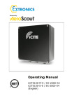
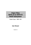
ECL-IP2B150V
User Manual
Network Camera
User Manual
Warranty
If the product does not operate properly in normal conditions, please let us know. We will
resolve the problem for free of charge. The warranty period is 1 years. However, the
followings are excluded:
If the system behaves abnormally because you run a program irrelevant to the system
operation.
Deteriorated performance or natural worn-out in process of time
2
IMPORTANT SAFETY INSTRUCTIONS
1.
Read these instructions.
2.
Keep these instructions.
3.
Heed all warnings.
4.
Follow all instructions.
5.
Do not use this apparatus near water.
6.
Clean only with dry cloth.
7. Do not block any ventilation openings, Install in accordance with the
manufacturer’s instructions.
8.
Do not install near any heat sources such as radiators, heat registers, stoves, or other
apparatus (including amplifiers) that produce heat.
9.
Do not defeat the safety purpose of the polarized or grounding-type plug. Apolarized
plug has two blades with one wider than the other. A grounding type plug has two
blades and a third grounding prong. The wide blade or the third prong are provided for
your safety. If the provided plug does not fit into your outlet, consult an electrician for
replacement of the obsolete outlet.
10.Protect the power cord from being walked on or pinched particularly at plugs, convenience
receptacles, and the point where they exit from the apparatus.
11.Only use attachments/ accessories specified by the
manufacturer.
12.Use only with the cart, stand, tripod, bracket, or table specified
by
13.The manufacturer, or sold with the apparatus. When a cart is used,
14.Use caution when moving the cart/apparatus combination to avoid
15.Injury from tip-over.
16.Unplug this apparatus during lighting storms or when unused for long periods of
time.
17.Refer all servicing to qualified service personnel. Servicing is required when theapparatus
has been damaged in any way, such as power-supply cord or
plug isdamaged, liquid has been spilled or objects have fallen into the
3
apparatus, theapparatushas been exposed to rain or moisture, does not
operate normally, or has been dropped.
WARNING
TO REDUCE THE RISK OF FIRE OR ELECTRIC SHOCK, DO NOT EXPOSE THIS
PRODUCT TO RAIN OR MOISTURE. DO NOT INSERT ANY METALLIC OBJECT
THROUGH THE VENTILATION GRILLS OR OTHER OPENNINGS
ON THE EQUIPMENT.
Apparatus shall not be exposed to dripping or splashing and that no objects filled with
liquids, such as vases, shall be placed on the apparatus.
CAUTION
EXPLANATION OF GRAPHICAL SYMBOLS
The lightning flash with arrowhead symbol, within an
equilateral triangle, is intended to alert the user to the
presence of “dangerous voltage” within the product’s
enclosure that may be of sufficient magnitude to constitute a risk of
electric shock to persons.
The exclamation point within an equilateral triangle is
intended
to alert the user to the presence of important operating and
maintenance (servicing) instructions in the literature accompanying
the product.
Battery
Batteries(battery pack or batteries installed) shall not be exposed to excessive heat such as
sunshine, fire or the like.
Disconnection Device
Disconnect the main plug from the apparatus, if it’s defected. And please call
4
a repair man in your location.
When used outside of the U.S., it may be used HAR code with fittings of an
approved agency is employed.
CAUTION
These servicing instructions are for use by qualified service personnel only. To reduce the
risk of electric shock do not perform any servicing other than
that contained in the operating instructions unless you are qualified to do so.
The BNC Out terminal of the product is provided for easier installation, and is not
recommended for monitoring purposes.
If you keep the BNC cable connected, a risk of lightening may cause damage or
malfunction to the product.
Please use the input power with just one camera and other devices must not be
connected.
Please read the following recommend safety precautions carefully.
l
Do not place this apparatus on an uneven surface.
l
Do not install on a surface where it is exposed to direct sunlight, near
l
heating equipment or heavy cold area.
l
Do not place this apparatus near conductive material.
l
Do not attempt to service this apparatus yourself.
l
Do not place a glass of water on the product.
l
Do not install near any magnetic sources.
l
Do not block any ventilation openings.
l
Do not place heavy items on the product.
User’s Manual is a guidance book for how to use the products. The
meaning of the symbols are shown below.
l
Reference : In case of providing information for helping of product’s usages
l
Notice : If there’s any possibility to occur any damages for the goods and human
caused by not following the instruction
l
Please read this manual for the safety before using of goods and keep it in the safe
place.
5
PRODUCT FEATURES
l
Full HD Video Quality
l
Super Low Light
l
Super WDR
l
Multi-Streaming
l
This network camera can display videos in different resolutions and qualities
simultaneously using different CODECs.
Web Browser-based Monitoring
l
Using the Internet web browser to display the image in a local network
environment.
Alarm
l
If an event occurs, the event-related video will be transferred to the email specified
by theuser or saved to the SD memory, or the event signal will be sent to the Alarm
Out port.
Video Motion Detection
l
Detects a motion from the video before triggering an event.
Intelligent Video Surveillance
l
Network camera with IVS support intelligent functions, such as auto detection of any
abnormal faults, cross-line alarm, area alarm, object left or lost alarm,counting.
PoE
l
Power OverEthernet.
ONVIF Compliance
All these network camera series support ONVIF For
more information, refer to www.onvif.org.
RECOMENDED PC SPECIFICATIONS
l
CPU : Intel Core 2 Duo 2.4GHz or higher
l
Operating System : Windows XP, VISTA, 7, Mac OS
l
Resolution : 1280X1024 pixels or higher
l
RAM : 2GB or higher
l
Web Browser : Internet Explorer 7.0 or higher.
l
If connecting to IPv6 in Windows XP, it can cause some problem.
l
It is recommended to connect to IPv6 in Windows 7.
l
Video Memory : 256MB or higher
6
Connecting with other devices
7
Overview
Contents
OPERATION..........................................................................................................................
1.PLUG-IN INSTALLATION.........................................................................................
2.IE LONG IN ....................................................................................................................
3.BROWSING INTERFACE ...........................................................................................
3.1 ADD EQUIPMENT ............................................................... ................................ ...................
3.2 VIDEO BROWSING ............................................................... ................................ ................
3.3 PTZ CONTROL ............................................................... ................................ ......................
4.VIDEO PLAYBACK .......................................................................................................
4.1 VIDEO FILES LIST ............................................................... ................................ .................
4.2 LOCAL R EPLAY ............................................................... ................................ ......................
4.3 PLAYBACK CONTROLS............................................................... ................................ ...........
4.4 OPERATION OF VIDEO PLAYBACK ............................... ................................ .........................
5 PARAMETERS SETTING...............................................................................................
5.1 GENERAL S ETTING ............................................................... ................................ ...............
5.2 VIDEO PARAM................................................................ ................................ ......................
5.3 HD SETTING ............................................................... ................................ .........................
5.4 OSD............................... ................................ ................................................................ ......
5.5 ALARM SETTING............................................................... ................................ ....................
5.6 NETWORK PARAMETER ............................... ................................................................ .........
5.7 F RONT STORAGE ............................................................... ................................ ..................
5.8 ADVANCE ............................... ................................ ...............................................................
6.0 SUPPLEMENT ............................................................... ................................ .........................
8
Overview
Operation
[Tip]: The initial IP address of the device is 192.168.1.2. Please change the IP address of
your computer to the same network segment, and then access the camera via LAN. Login
account: Admin
Password: Admin
Please notice that the login account and password are case-sensitive.
1.Plug-in installation
When using the network video products for the first time, an ActiveX control is needed.
Before downloading ActiveX, the IE settings should be done appropriately.
[1]: Using IE6
① Open IE, click "Tools - Internet Options - Security - Internet - Custom
Level" (Pic.1.1), and all ActiveX controls and plug settings should be enabled
(Pic.1.2).
Pic.1.1
Pic.1.2
② Click "Security - Local Internet - Custom level", all ActiveX controls and plug
settings should be enabled.
③ If the operating system is Windows XP, the IP address of the device
should be added to "Trusted sites" (Pic.1.3) Click "Safety - Site", enter the IP address,
such as: http://192.168.1.2, and cancel "Require server verification for all sites in this
zone", then click "Add" and "OK" button to complete.
9
Overview
Pic.1.3
[Tip]: After the controls have been downloaded please restore security settings to
"Default level".
[2]: Using IE8
① Open IE, click "Options - Security Settings" to modify the ActiveX
configuration. For unsigned ActiveX components please choose "Promote".
(Pic.1.4)
Pic.1.4.
② Open IE8, login the server, there will be a security warning, run this
ActiveX control.
③
Modify
authority
setting, please enable the setting "Include local
directory path when uploading files to a server" (Pic.1.5).
10
Overview
Pic.1.5.
Basic Setting Table
Item
Default Setting
Network
Static IP/Dynamic IP
Static IP
IP Server Enable
Enable
IP Address
192.168.1.2
Gateway
192.168.1.1
Subnet Mask
255.255.255.0
Web Connection Port
80
RTSP Port
554
RTP Port Range
5000 ~ 5999
ID and Password
Administrator
ID/Password
User ID/Password
Admin/Admin
root/root, guest/guest
Domain of Related
Server
DDNS Server
Stream setting
Stream 1
Stream 2
H.264
H.264
1080P@30fps
720x576@30fps/
640x480@30fps
11
Overview
<Caution>Make sure that IP address of network cameras and host in
the same segment.
2.IE Long in
Enter IP address and password of device, enter login interface,Pic 2.1:
Pic2.1 Login interface
Click 【Log on】button to enter the system.
3.Browsing interface
After log in enter into the video browsing module, as shown in Pic 3.1.
Pic 3.1 Video browse interface
12
Overview
3.1 Add equipment
In the tree area, click the right mouse button will pop-up menu, click [Add
Device], the system pops up the dialog box shown in Pic 3.2.
Pic 3.2 Add device interface
Input device IP, port, username, and password,
click "Log On" to add
equipment, new equipment added successfully will be in the tree table. As
shown in Pic 3.3.
Pic 3.3 Add devices successfully
Overview
3.2 Video browsing
3.2.1 Connect the video
Double-click the stream channel connecting video, the middle of the page is the video
display area, can display up to 16-screen video, use the control buttons below
the video display area can modify the number of frames of the video display area or the
selected video channel to capture or operate, as shown
in Pic 3.4.
Pic 3.4
: Single-screen video display.
: 4 screen display video.
: 9 screen video display.
: 16 screen video display.
14
Overview
: Full-screen video of the selected channel.
: Audio player selected channel.
: Operate the video of selected channel.
: Intercom with equipment corresponding selected channel.
: Snapshot the selected channel.
3.2.2 Change the size of the video window
The system supports double-click to change the video size to support the small screen,
single-screen, and full-screen.
3.2.3 Video Drag
The system supports the browser screen drag, right click to drag, left click to change
the video display size of the window, click the right mouse button to change back to
the original size.
Pic 3.5 Drag to change the size of the video window
15
Overview
3.2.4 Electronic Amplification
The system supports electronic zoom function, click the right mouse button
in the video display area in the pop-up menu, choose the electronic zoom, select
a region by draw a rectangle by click left button, and the region will be amplified.
Step 1: select electronic amplification
Step 2: Hold the left mouse button to draw a rectangle
Step 3: release the left mouse button
16
Overview
3.3 PTZ Control
The right side of the browser interface is the the PTZ control area, as shown in Pic 3.6.
Pic 3.6 PTZ control area
17
Overview
3.3.1 Key Description
: Video Brightness (range 0 to 100);
: Video contrast ratio (range 0 to 100);
: Video saturation (range 0 to 100);
: Video tone (range 0 to 100);
: Lighting;
: Power;
Overview
: Wiper;
3.3.2 Function Description
PTZ control, including: the direction of rotation, speed, zoom, focus,
aperture, power, lights, wipers.
Protocol support:
DOME-PELCO-D
DOME-PELCO-P
DOME-TIANDY
PTZ-PELCO-D PTZPELCO-P PTZTC615-P
The baud rate can not be changed.
The system supports automatic identification of PTZ device; log on connected devices,
the system will distribute the device protocol, baud rate and address. The system supports
preset call and up to 255 preset positions.
The system can be set to control the speed (range 0 to 100), and control
PTZ.
19
Overview
4.Video playback
Click the video replay button in the main window into the video playback window, as
shown in Pic 4.1:
Pic 4.1 Video playback window
4.1 Video files list
After the above settings, qualified results will be displayed on the video file list, Pic
4.2. The list lists all the results that match the query conditions, displays video files
basic information: file name, file type (remote / local), start time, file size.
Pic 4.2 Video screening results
20
Overview
Key description:
Key
Description:
Return to home page
Previous page
Next page
Last page
Download selected remote video files to local computer
User can also select page directly through drop-down menu, to find wanted
video files.
For remote video file, user can click on the download button to download the selected
video file to the local PC.
4.2 Local Replay
Click browser to select a local video file, and click the Open button to start playing, as
shown in Pic 4.3.
Pic 4.3
video replay
4.3 Playback Controls
Pic 4.4 shows the main window of the display and control. The videos through search
or selected local file can be played in the window.
21
Overview
Pic 4.4 Display and control window
Key description:
Key
Description
Play video file
Halt
Stop
Single frame
Fast forward playback speed by 2
Slow forward playback speed divided by 2
Snapshot, click the button to save still
mute
22
Overview
Video file playback
progress
progress bar to positioning.
bar,
drag
the
Note: Only playback local video can drag to positioning.
4.4 Operation of video playback
1.
According to the conditions specified to search video file.
① Select Server list
② If user wants to search remote video file, then click remote check box,
if user want to search local file then do not need to check.
③ Select the file type; select a file type in the "file type" drop-down list.
④ If user wants to search remote video files, then need to select video type, select
a video type in the drop-down menu.
⑤ Select a channel, select a video input channel.
⑥ Double click on a certain day in the calendar can find all videos in that day.
2.
Play
Select a file in the list of video files, click
to halt, click
to stop, click
to start playback selected file, click
to play by frame, click
speed to play selected file, click
/2 speed to play selected file, click
1
the picture of select video, click
s
stop preview audio.
23
double
napshot
Overview
5 Parameters Setting
On video preview mode, click Parameters Setting, and this mode includes General
Setting, Video Param, HD Setting, OSD, Alarm Setting, Network Param., Advance, PTZ and
Cruising.
5.1 General Setting
l
Pic.5.1 General Setting
Channel Num.:Ch 1 Major and Vice
l
Set Video Cover Area:Select to confirm using and setting video cover area, and select
Clean Area to cancel.
l
Showing
Frame-rate
and
Bit-stream
Information : Select
displaying frame-rate and bit stream.
l
Local Storage Path: Set storage path of recording and snapshot.
24
to
confirm
Overview
l
Local Rec. File Type:Set local recording file type, there are two types: H.264
and AVI.
l
Front Device Snapshot:Snapshot from front SD card or NFS
5.2 Video Param.
Pic. 5.2 Video Param.
l
Channel Num.:Channel 1 Major and Channel 1 Vice
l
Video Quality:If on Variable Bit Rate (VBR), it needs to select video quality. There are
5 levels, Best, Better, Good, Average and Worse, and image quality and bit
rate is proportional.
l
Frame Rate: Options are 30, 25, 20, 15, 10, 5 and 1fps/s. The 30fps/s is
only available when NTSC.
l
Stream Type:Video or Audio&Video
l
Prefer Mode:Quality or Frame Rate
25
Overview
l
Rate:Can be set. When select VBR, if compress dramatic movement videos,
it needs to set an upper limit. Stream rate is the limit value, and the scope
is 32Kbps-8192Kbps. The bit rate setting is proportional to the resolution, if higher
resolution, the set value of bit rate should be higher. For CIF, typically set as 384K768Kbps; 2CIF, 512K-1Mbps; 4CIF, 768K-2Mbps. Concrete bit rate should be adjusted
according to cameras position.
l
Resolution: VGA, 4CIF, 720P, 960P are optional. Higher resolution and
clearer image.
l
N/P Mode:NTSC or PAL
l
I Frame Rate: It is the key frame. The video frame is composed by key frames
and non-key frames. I frame rate refers to the number of video frames in the data
stream includes an I-frame. If I frame rate is 100, means there is a I frame every 100
frames. I frame the frame rate and bit rate is inversely proportional, larger I frame
and smaller bit rate. It is advised that
I-frame rate setting value is four times of frame rate.
l
Encode Mode:VBR(Variable Bit Rate) or CBR(Constant Bit Rate)
The BVR means when compression video signal, it can change bit rate
according to the video source. For example: decrease compression rate for stable image,
otherwise, raise it. Thus, it can save the hard disk space and enhance bandwidth
utilization. The main features of VBR are video quality unchanged and compressed
stream adjusted according to video source. Given bit rate means that no matter what
happens to the video source, video share hard disk space and The CBR means the
compression bit rate is unchanged,
hard
disks
space
and
it
can
accurate
estimate
and bandwidth occupied by recordings.
l
Video Encoder:Support H.264 and Motion JPEG
l
Play Impression:Low Delay and Fluent
l
Extended Code:Support H.264 baseline, main profile and high profile
26
the
Overview
5.3 HD Setting
5.3.1 HD Setting
Parameters setting as Pic.5.3, support Auto Iris, WDR (open default), BLC, Exposure
Time,
Shutter
Speed,
Gain,
Gamma,
Sharpness,
Denoise,
Bright,
BLC(auto&manual), and 8 setting template can be saved.
Pic. 5.3 HD Setting
5.3.2 HD Schedule
8 templates will be shown here, as Pic. 5.4, each template has a particular color. Set
different time periods using different templates by controlling the
27
Overview
"Settings" button at the top bar. For example: Time period: 00:00~05:40, using
day-indoor(white), 05:40~14:10 using night-indoor(blue),14:10~23:59 using nightoutdoor(green).
Pic. 5.4 HD Schedule
5.3.3 Color to Gray
It
has
four
synchronization,
modes:
and
Pic.
color,
5.5
gray,
internal
only showed
the
synchronization
internal
and
external
synchronization,
the
brightness in day and night only works in this mode.
Daytime Brightness:If real-time brightness is larger than day brightness, it
will turn to color mode, and recommended value is 100.
Night Brightness: If real-time brightness is smaller than night brightness, it will turn to
gray mode, and recommended value is 45.
28
Overview
Alarm
Recommended:
If
alarm
synchronization
interface
(SYNC)
is
short-circuit, it will turn to gray mode, and short-circuit disconnected will change
to color mode
Pic. 5.5 Color To Gray
29
Overview
5.4 OSD
Pic. 5.6 OSD
l
Support OSD setting to different channels
l
Support channel name setting. The system can set channel name for each video and
display on it. When local video preview, playback and network video preview, the
channel
name
will
always
display
on
the
video.
The maximum length of
channel name is 32 bytes.
l
Support
OSD
type
settings,
there
is
No
OSD,
Time+Channel four options.
l
Set horizontal and vertical coordinates of date position.
l
Set horizontal and vertical coordinates of channel name.
l
Set OSD content.
l
Set horizontal and vertical coordinates of OSD position
30
Time,
Channel
and
Overview
5.5 Alarm Setting
5.5.1 Motion Alarm
Select ‘Set Motion Detect Area’ and move the mouse to video and drag it to set motion
alarm area, as Pic. 5.7
Pic. 5.7 Motion Alarm
l
Set motion alarm for different channels.
l
Enable motion alarm.
l
Set motion alarm area and threshold.
l
Set motion alarm template.
l
Set motion alarm link out.
31
Overview
5.5.2 Lost Alarm
Select Channel Num. and Enable, and select date in Schedule to set, as 5.8.
Pic. 5.8 Lost Alarm
l
Set motion alarm for different channels.
l
Enable lost alarm.
l
Set lost alarm template.
l
Set lost alarm link out, Support alarm and PTZ preset and cruising.
5.5.3 Port Alarm
Select Input and output port and Enable to set mode, as Pic. 5.9
32
Overview
Pic. 5.9 Port Alarm
l
Enable motion alarm.
l
Set input and output port alarm trigger type.
l
Set port alarm template.
l
Set port alarm link out, Support alarm and PTZ preset and cruising.
5.5.4 Cover Alarm
Select Channel Num. and enable, and set video cover threshold, as Pic. 5.10.
33
Overview
Pic. 5.10 Cover Alarm
l
Set cover alarm for different channels.
l
Enable cover alarm.
l
Set cover alarm threshold.
l
Set cover alarm template.
l
Set motion alarm link out. Support alarm and PTZ preset and cruising
5.5.5 Alarm Server
Input alarm server address and set alarm port, as Pic. 5.11
34
Overview
Pic. 5.11 Alarm Server
l
Set alarm sever IP and port
l
Set COM server IP and port.
35
Overview
5.5.6 Email Alarm
Pic. 5.12 Email Alarm
l
Set email SMTP server and port.
l
Set email account and password.
l
Set email address, max 4.
l
Set email subject
5.6 Network Parameter
Support Wire Setting, WEB Port, Registration Center, DDNS Setting, PPPOE Setting, FTP
and NTP Setting.
5.6.1 Wire Setting
Support IP address, Sub Mask, Gateway, DNS and MAC. IP address can be
36
Overview
obtained automatically or manually.
Pic. 5.13 IP Setting
5.6.2 Registration Center
Support User Name, Password, Server Name, IP and Port setting.
Pic. 5.14 Registration Center
37
Overview
5.6.3 DDNS
Support Server Domain, DDNS Domain, Port, User Name and Password setting.
Pic. 5.15 DDNS
5.6.4 PPPOE
Set user name and password.
Pic. 5.16 PPPOE
38
Overview
5.6.5 FTP
Support FTP Server Url, FTP Port, Path, User Name and Password setting. Upload
support automatically and manually, also recorder and picture timing.
Pic 5.17 FTP
5.6.6 NTP
Support NTP Server, Port and Interval setting.
Pic. 5.18 NTP
5.7 Front Storage
Front storage contains SATA, USB/SD, NFS, Record Policy, Pre-record,
Storage Policy and Snapshot.
39
Overview
5.7.1 SATA
It contains Device No., Status, Usage, Part Num., Total Size and Free Space.
5.19 SATA
5.7.2 USB/SD
Support Device No., Status, Usage, Total Size, Free Space and Initialize Disk setting.
Pic. 5.20 USB/SD
5.7.3 NFS
Support Device No., Status, Usage, Total Size, Free Space, IP address and
Mapping Path setting.
40
Overview
Pic. 5.21 NFS
5.7.4 Record Policy
Support Alarm Record, Manual Record, Task Record, Channel Num and
Record Status.
41
Overview
Pic. 5.22 Record Policy
5.7.5 Pre-recorded
Support Channel Num., Alarm Pre-record Time and Alarm Record Delay setting.
There are 5, 10 and 15 seconds optional, for Alarm Record Delay, there are 10, 15, 30 and
60 optional.
42
Overview
Pic. 5.23 Pre-recorded Alarm
5.7.6 Storage Policy
Support Pack Type (by time or by size), Free Disk Space(more than 200M) and
Saving Strategy setting. The Pack By Time has 10, 20, 30 and 60 optional.
Saving Strategy has Stop Record and Cycle Del(Except Alarm File)
Pic. 5.24 Storage Policy
5.7.7 Snapshot Setting
Select Channel Num and enable Timer Capture, then set Interval, and click
Set to complete.
43
Overview
Pic. 5.25 Snapshot Setting
5.8 Advance
Support Version Information, System Information, PU, SIP, Access Platform, User
Management, Upgrade and Log Management setting.
5.8.1 Version Information
It will show SDK Version, Kernel Version, Web Version and Factory ID
information, as Pic. 5.26
44
Overview
Pic. 5.26 Version Information
5.8.2 System Information
It will show CPU, Memory, Flash and System Time information.
Pic. 5.27 System Information
5.8.3 PU Set
l
Set Channel Num.
l
Set Register Server, Heartbeat Server, Alarm Server and corresponding port.
l
Set Device ID, Device Name, VSP Port, VAP Port and Access Pass.
45
Overview
Pic. 5.28 PU Set
5.8.4 SIP Configuration
46
Overview
Pic. 5.29 SIP Configuration
5.8.5 Access Platform
Select platform list and click ‘Enable’. If select ‘Stop’, the device will restart.
Pic. 5.30 Access Platform
5.8.6 User Management
Support add and delete user. And the user authority contains Admin, View,
View+Control and View+Control+Set, it can set password for new user.
Pic. 5.31 User Management
47
Overview
5.8.7 Upgrade
The system support .bin to upgrade kernel and .Box to upgrade web. Click
[Browse] and select.bin or .box file, then select [Upgrade Kernel] or [Upgrade
Web], and the system will restart after completion.
Pic. 5.32 Upgrade
5.8.8 Log Management
Query log information according to channel, type and time.
48
Overview
Pic. 5.33 Log Management
6.0 Supplement
6.1 Clod Start on Low Temperature
If the temperature is lower than -30 degree, please reheat for 3-5 minis.
6.2 Lightning Level
4KV electrostatic protection
Power port: mold 4KV, differential mode 2KV.
Network port: common mode 4KV.
49
Overview
The electrostatic: contact 6KV, air 8KV.
6.3 The Braids Lines Traces
In order to prevent water from braids line, please note braid line traces.
50