1
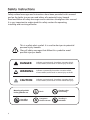
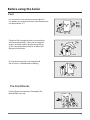
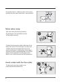
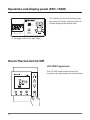
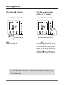
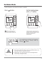
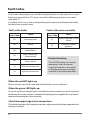
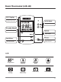
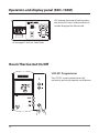
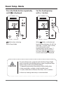
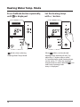
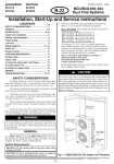
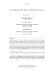
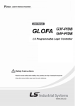
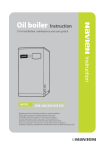
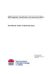
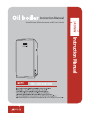
Instruction Manual
Installation, Maintenance and User Guide
Instruction Manual
NHC 25B/30B/41B
S
Contents
Safety instructions
Before using the boiler
Room Thermostat (LCR-2WE)
4
5
11
Operation and display panel (KDC-106M)
12
Heating Mode
13
Vacation / Stanby Mode
14
Hot water Mode
15
Fault codes
16
Room Thermostat (LCR-2D)
17
Operation and display panel (KDC-106M)
18
Room Temp. Mode
19
Heating Water Temp. Mode
20
Timer Mode
21
Boost Mode
22
Vacation / Stanby Mode
22
Hot Water Mode
23
Remote operation by telephone (LCR-2D only)
24
OTC Mode
Safety devices
Everyday checks
How to install
Room thermostat installation
Room thermostat (LCR-2WE)
Room thermostat (LCR-2D)
How to replace the parts
Electric Wiring diagram
Troubleshooting
Fault code
Specifications
26
27
28
31
35
36
37
38
39
40
41
42
4BGFUZ*OTUSVDUJPOT
Safety-related messages and instructions have been provided in this manual
and on the boiler to warn you and others of a potential injury hazard.
Read and follow all safety messages and instructions throughout this manual.
It is very important to understand this safety section for operating,
installing and servicing of boiler.
This is a safety alert symbol. It is used to alert you to potential
personal injury hazards.
Obey all safety messages that follow this symbol to avoid
possible injury or death.
DANGER
Indicates an imminently hazardous situation which,
if not avoided, could result in severe injury or death.
WARNING
Indicates a potentially hazardous situation which,
if not avoided, could result in severe injury or death.
CAUTION
Indicates an imminently hazardous situation which,
if not avoided, could result in minor moderate injury.
Meaning of symbols
in the guide for use
Use offi re
forbidden
Earth
Caution when
dismantling
Dangerous
electric current
Touching is
forbidden
Before using the boiler
Fuel
It is essential to use only kerosene or light oil.
It is better to use kerosene when the temperature
can drop below -5 ˚C.
Choose a fuel storage location in accordance
with local regulations. Take care to avoid the
ingress of water and/or dirt during re-filling
as this can lead to fiame failure or affect the
lifespan of the boiler.
Ensure that the power is turned off and
the oil tank is isolated before refilling.
Pre-StartChecks
Check all pipe connections thoroughly for
leaks before start-up.
5
Ensure that there is sufficient water in the system
and that the low water level alarm is not activated.
/PUFTXIFOVTJOH
Take care when positioning the boiler.
Do not locate in the immediate vicinity
of flammable materials.
Confirm that the ignition and combustion of the
boiler are normal. Use the flue gas test port and
suitable measurement equipment to ensure
correct combustion is taking place. If the boiler is
not being used for extended periods turn off the
power via the controller. Do not plug out the
boiler as this will de-activate the frost protection.
"WPJEDPOUBDUXJUIUIFGMVFPVUMFU
The domestic hot water supply is not
recommended for potable use.
6
)PXUPVTF
1VSHJOHUIFPJMTVQQMZ
Avoid complete emptying of the oil tank.
This can lead to air being introduced to
the fuel system and may result in ignition failure.
Loosen the screw in the oil filter. This will allow
the fuel supply line to vent. When oil starts to
flow re-tighten the screw (this is only possible
in positive head oil supply applications).
In negative head oil supply applications the
fuel supply line must be purged using the
oil pump vent screw. For this the oil filter
screw must be in the tightened position.
Open the oil pump vent screw and switch
on the power to the boiler. After 6-7 seconds
the pump has purged the air and the
“CHECK” light will show on the control panel.
The boiler will stop.
7
Press the power button on the control panel
repeatedly until the oil flow is constant. Close the
oil pump vent screw, press the power button again
and the boiler will ignite. If the boiler fails to fire
after 3 successive attempts contact the Technical.
Preparation and checking before start-up
Ensure the system is full and at suitable
operation pressures. Fill and thoroughly
purge all connected pipework.
The boiler must always be correctly
grounded according to relevant local regulations.
Connect the boiler to the main 220v supply
and press the power button. The “RUN”
light should show after a short period.
8
How to use
Set the temperature on the main control
panel to the desired operation temperature.
Press the power button to start the fan
motor and the boiler combustion.
Ifi gnition fails the “CHECK” light will show.
In this case press the power button again
to reset. If successive flame failures occur
contact the Technical.
9
Component Overview
The structure of the boiler
ModelNo: NHC 25B/30B/41B
1
FLAME DETECTOR(Cds)
2
10
PRE-HEATER
3 CONTROLLER
5
NEUTRALIZATION ASSEMBLY
6
ELECTRONIC PUMP
7
BOOSTER PUMP
8
OIL FILTER
Room Thermostat(LCR-2WE)
LCD Display
LED Lamp
Indicating each
function and status
Operation/Service
Up/Down
Adjusting Temp.
Heating
Heating Mode
Power
Room Thermostat
Power ON/OFF
Standby Mode
Hot Water
Standby Setting Mode
Hot Water Mode
LCD
Temperature
Operation
Indicator
Hot water
Mode
Hot water Temperature
(Lo/Mid/Hi)
Heating
Mode
Standby
Mode
11
Operation and display panel (KDC-106M)
LED indicate the temp of heating water,
the value of K-Factor, and occurrence of
trouble displayed the failure code
05$
,'"$503
Ⲽ See page 16 for Error Code Table
Room Thermostat On/Off
LCR-2WE Programmer
The LCR-2WE remote control panel will
activate by pushing the power on/off button.
12
Heating mode
Press the
button.
blinks when selecting
Room Temp. Mode
Set the heating temp.
with ⶹⶽ button.
when
blinks, set the desired
heating temp. between 40~80˚C by
adjusting ⶹⶽbutton, after a while,
it is automatically saved. Heating
temp. can be set by 1˚C. After the
required temperature has been
selected,
is on and current
heating water temp. is displayed.
The LCR-2WE room thermostat is designed to control a heating system
according to time and temperature, in connection with a valve controller
(red colored cable).
13
Vacation/Standby Mode
If you are not at home, you can set the Standby Mode to save heating
energy by pressing.
Press
button.
will be displayed and Standby Mode
will be set.
To cancel vacation/standby mode press the
button to return to the heating mode.
14
Hot Water Mode
Use this function only when hot water is needed.
Press
button.
will be displayed and
Hot Water Mode will be set .
Set the heating temp.
with ⶹⶽbutton.
Adjusting hot water temp. by
3step; Low load, Medium load ,
High load capacity of
combustion.
You can determine whether the changeover
from DHW mode to Heating mode by
pushing “
" button.
1. Please be careful that infants and young children do not use
hot water without a guardian present.
CAUTION
2. While others are using hot water, do not change the hot
water temp. setting for safety.
15
Fault Codes
Fault codes take priority over all other display functions in the event of a system
fault occurring and the LCD shows one of the following numeric error codes
with letter 'E'.
If multiple faults occur, the corresponding fault codes are displayed alternately
for about two seconds each.
Fault at the boiler
Fault at the room controller
Error Code
Cause
Error Code
Cause
02
Low water level
51
Electrical backup system
failure
03
Misfire
52
Functional button
defective
04
Pseudo-flame
05
Temp. sensor wire
disconnected
06
Short circuit of
Temp. sensor
12
Misfire in combustion
16
High limit thermostat
Electrical backup
The LCR-2WE retains the setting
parameters when the power
supply to the boiler is turned off
or shut down by power outages
and back to the preset operation.
When the red LED lights up
Please contact your local shop and distributor for service solutions.
When the green LED lights up
Check to see if zone control valves are defective then contact your local shop and
distributor for service solutions, meanwhile heating can be supplied thru an interim
measure to operate the valve manually.
Check the output signal wire connections.
If the boiler operates the heating mode then adjustment of setting temperature of
heating is needed.
16
Room Thermostat (LCR-2D)
LCD Display
Indicating each
function and status
UP/DOWN
Temp. & Timer Mode
Standby Mode
Standby Setting Mode
MODE
Select Mode
Power
Hot Water
Room Thermostat
Power ON/OFF
Hot Water Mode
LCD
Temperature
Operation
Indicator
Hot water
Mode
Standby
Mode
Timer
Heating
Heating
Water Temp.
Room Temp
Power Heating
17
Operation and display panel (KDC-106M)
LED indicate the temp of heating water,
the value of K-Factor, and occurrence of
trouble displayed the failure code
05$
,'"$503
Ⲽ See page 41 for Error Code Table
Room Thermostat On/Off
LCR-2D Programmer
The LCR-2D remote control panel will
activate by pushing the power on/off button.
18
Room Temp. Mode
Press the Mode button repeatedly,
until is displayed.
Set the heatingtemp.
with +/- button.
blinks when selecting
Room Temp. Mode
When
blinks, set the desired
heating temp. between 10~40˚C by
adjusting +/- button, after a while,
it is automatically saved.
Heating temp. can be set by 1˚C .
After the required temperature
has been selected ,
is on and
current room temp. is displayed.
CAUTION
If a room thermostat is programmed with Room Temp. Mode
and it is placed in the following places when using Room Temp.
mode, it may result in some false readings.
1. Frequently opened and closed door and/or drafty place.
2. Areas exposed to sunlight or high humidity levels.
3. A place under direct influence from heat, such as radiator.
In that case, heating water temp. is recommended.
19
Heating Water Temp. Mode
Press theMode button repeatedly,
until
is displayed.
Set the heating temp.
with +/- button.
blinks when selecting
Heating Water Temp. Mode
When
blinks, set the desired
heating temp. between 40~80˚C by
adjusting +/- button, after a while,
it is automatically saved. Heating temp.
can be set by 1˚C. After the required
temperature has been selected,
is on
and current heating water
temp. is displayed.
20
Timer Mode
In this case the Timer mode is a manual over-ride to allow the home owner to boost
the heating as required. A separate 2 or 3 channel programmer is required as normal.
Press the Mode button repeatedly,
until
is displayed.
blinks when selecting Timer Mode.
CAUTION
Set the heating stop time
with +/- button
When
blinks, set the desired
heating stop time.
It can be set between 10 &15 minutes
in the range of 0-9 hours by adjusting
+/- button, after a while, it is
automatically saved.
After the required temperature has
been selected,
is on and current
room temp. is displayed.
Selecting a stop time of '0' means the boiler is always active.
The boiler is then controlled by an external 7 day
programmer/time clock.
21
Boost Mode
Press the Mode button repeatedly,
until
is displayed.
When selecting Boost Mode,
is displayed
and the boiler will run for 30 minutes continuously.
After 30 minutes, it returns to previous
Heating Mode.
Vacation/Standby Mode
Selecting this mode allows the boiler to operate at minimum capacity when
there is no one at home. It does not over-ride the frost protection features of
the boiler during winter.
Press
button
will be displayed and Standby Mode
will be set.
To cancel vacation/standby mode press the mode
button to return to the desired heating mode.
22
Hot water Mode
Use this function only when hot water is needed.
Press
button.
will be displayed and Hot Water
Mode will be set.
In hot water mode the boiler temperature will not
exceed 60˚C to avoid excessive energy use.
Press the MODE button and select
the desired Heating Mode to cancel
the Hot Water Mode.
CAUTION
1. Please be careful that infants and young children do not use
hot water without a guardian present.
2. While others are using hot water, do not change the hot
water temp. setting for safety.
23
Remote operation by telephone (LCR-2D only)
With a phone network, the heating function of the room thermostat can be set.
Activating the boiler
1. Press "#" button 3 times.
2. Hang up the phone, when hearing
'beep-beep' sound.
AM
AM
1
2
3
4
5
6
7
8
9
*
0
#
#
#
#
#
1
2
3
4
5
6
7
8
9
*
0
#
CM
CM
The boiler is operated in‘Boost Mode‘ for 30 minutes and then returns to
the previous mode (If the room thermostat is o , return to Standby Mode.)
Suspending the boiler
1. Press "*" button 3 times.
2. Hang up the phone, when hearing ‘
'beep-beep-beep' sound.
Then, it’s changed to Standby Mode
AM
AM
1
2
3
4
5
6
*
TIP
24
7
8
9
*
0
#
CM
*
*
*
1
2
3
4
5
6
7
8
9
*
0
#
CM
When using an outside telephone, call the phone, once the call is connected to
the boiler after ringing the preset number of times, you will hear a 'beep' sound.
Then, follow the steps as described above.
To alter the number of rings
1. Press"0" button 3 times.
2. 'beep-beep-beep-beep'
sound will be ring 4 times.
AM
AM
1
2
3
4
5
6
7
8
9
0
#
*
0
1
2
3
4
5
6
0
7
8
9
0
*
0
#
0
CM
CM
3. Press a button you select out of
5,6,7,8,9, or 0 three times.
4. After 'beep-beep-beep-beep-beep'
sound, hang up the phone.
AM
AM
1
2
3
1
2
3
4
5
6
4
5
6
7
8
9
7
8
9
*
0
#
*
0
#
CM
CAUTION
CM
1. If you don't press any buttons for 10 seconds or longer after
pressing '#' or '*' button, the telephone will automatically
hang up.
2. Make sure to hang up the phone after hearing activation
or suspension signal.
3. If you don't hear the 'beep' sound while using it, follow steps
again slowly.
25
OTC Mode
If an outdoor temperature probe is connected, the weather compensation
function can be used.
1) With this function, the target primary temperaturis automatically
set according to the outdoor temperature (K-Factor)
2) When the outdoor temperature sensor is connected, OTC lamp is turned on
3) Each time the Outdoor Temperature sensor should be placrd,
comply with the instruction and to avoid areas with temperature fluctuations
caused by direct sun exposure.
4) Ensure the Outdoor Temperature sensor should be placed with a constant
temperature of Outside.
CPJMFSTFUQPJOU
,
,
,
,
,
FYUFSOBMUFNQFSBUVSF
K-Factor
26
Safety devices
Ignition safety device
deactivate the boiler.
Low water level safety device
the low water level sensor will deactivate
the boiler. Once the system is adequately
Overheat prevention
If the temperature of the boiler rises to
dangerously high levels the overheat
sensor will deactivate the boiler.
In this instance the “CHECK” light will show.
Once the temperature has dropped to
safe levels the boiler will auto-reset
and the “RUN” light will show.
Frost freezing prevention
During times off rost risk the boiler will
activate the circulating pump and/or
the burner as required to eliminate
the risk off reezing. For this reason,
power must be maintained to boiler,
even if the system is not in use.
Power-failure protection
In the event of power failure the oil supply
will automatically be isolated from the
combustion chamber.
27
Everyday checks
Points to be checked once or more a year
Ensure that combustible materials are
not stored near the boiler.
Keep the area around the boiler clean and free
from obstruction to allow for free air flow.
Check for fuel leaks within the fuel
storage/supply system and check for
water leaks within and around the boiler.
Inspect the inside of the oil tank
for water or debris.
28
Cleaning of the boiler
Soot build-up within the boiler will reduce its
operating efficiency and life expectancy.
The boiler should be serviced annually
by an approved service engineer.
Cleaning the oil filter
To clean the oil filter, first isolate the oil supply.
Remove the oil cup by turning right
and left and by simultaneously
pulling the cup downwards.
Wash the filter and the inside of the oil
cup using clean kerosene.
Cleaning the oil tank
The oil tank should be checked during the
annual service and cleaned of all water
and debris as required.
29
Cleaning the flame detector
or dirty the reduced sensitivity will cause
erratic and incorrect boiler operation.
is located at the top of the burner.
Wipe the glass surface of the fame detector
(photocell) using a clean rag and replace.
Checking the flue pipe
be checked for correct installation, blockages,
corrosion or leakage. Any abnormalities found
30
How to install
Choosing of the installation place
Choose an installation site that allows easy access for installation, maintenance and operation.
When choosing an installation site, take care to conform to all local regulations and standards.
Ensure that the boiler is accessible in order to allow for easy adjustment of the boiler temperature.
The boiler should not be sited close to storage areas of combustible materials.
Consider condensate and boiler drainage requirements when choosing the boiler location.
Thediagramofthestandardpiping:Cisterntankinstalltype
Open cistern tank
Expansion Tank
Water
Boiler Back
Hot Water Inlet
Hot Water Outlet
Never install any valve between
the boiler and cistern tank.
Supply Water
Pipe
Minimum 1.5m
Cold Water
Hot Water
Circulation Pump
Distributor
Heating Coil
Fan Coil
Radiator
Hot Water Outlet
Heating Water Distributor
Inlet
Condensate
Outlet
Drain
F.L
Drain
Install the condensate outlet hose for condensing model as above
Expansion Tank
Supply Water Pipe
Circulation Pump
Roop water
tank
Water
Expansion tank
Bypass Pipe
Install the pipe as above when circulation pump
install heating water inlet
Water
In case of water inlet through
roof water tank
31
Sealed System
Water
Boiler Back
Hot Water Inlet
Hot Water Outlet
Filter
Reducing Valve
Safety Valve
Air exhaust Valve
Check Valve
Cold Water
Circulation Pump
Distributor
Heating Water Outlet
Sealed Expansion Tank
Hot Water
Heating Coil
Fan Coil
Radiator
Filter
Reducing Valve
Condensate
Outlet
Drain
Circulation Pump
Check Valve
F.L
Drain
Bypass pipe
Install the condensate outlet hose for condensing model as above
Install the pipe as above when circulation pump
install heating water inlet
Precautions
1. The system should be installed with a pressure safety valve rated to 3.5 Bar or less.
2. The maximum operating pressure is 3.5 Bar. Neither the boiler nor any connected pipe
work should be exposed to pressures in excess of this.
3. Always install the boiler and the connected system according to local regulations.
32
Example of a standard installation
Flue Installation
no more than 2 bends be used.
Condensing boiler model : NHC25B/30B/41B
VENTILATING OPENING
FIRE WALL, SEMI FIRE WALL
FIREPROOF INSULATION
150mm OVER METERIAL
10˚ OVER
300mm OVER
AIR INLET
FIREPROOF INSULATION
METERIAL
made from heat-resistant non-corrosive material.
CAUTION
Allowing combustion gages gases to
re-enter the boiler room can result in a
build up of carbon monoxide which
could result in poisoning. Saturn
recommends the installation of a suitable
carbon monoxide detector where possible.
33
1. Condensate is produced when the condensing boiler is running and should
be piped to the drainage system.
2. Link the drain hose with the outlet of the neutralization system which is located
at the bottom of boiler and then connect the end of the hose to a soak pit.
3. Please make sure that the neutralizer in the boiler is filled with water.
4. The condensate drain system should be installed to minimise the risk of freezing.
Ensure the condensate is sent
to a suitable waste outlet in
accordance with regulations.
34
Room thermostat Installation
Safety (Electrical connection)
1. Room thermostat is mounted correctly and electrically connected.
2. The operating voltage of the LCR-2WE is DC 20V current supplied by the boiler controller.
Do not connect to any power supply voltage to the connections AC110/220 and DC power,
risk of damage to electronics!
Safety (Installation)
1. Install the room thermostat in dry rooms only and if the room thermostat is located
in the places that exposed to sunlight or high humidity levels, it may result in some
false readings.
2. Mount the room thermostat in such a way that the room temperature can be properly
evaluated; e.g. on an internal wall of the main living room, at the height of approx. 1.5m.
3. Please make sure that the air in the room can circulate freely and that the room thermostat
is not obscured by furniture, curtains or other objects.
4. All wiring must be connected to valve controller properly, risk of damage of electronics.
5. The disposal of the transportation packing is undertaken by the specialist company that
installed the equipment.
Safety (Use)
1. The room thermostat may only be installed by a suitably qualified engineer.
This engineer also assumes responsibility for installing the room thermostat properly
and putting it into service for the first time.
2. Connections carrying voltage!
There is a danger to life from electric shock when working in the switch box of the boiler.
Switch off the power supply to the switch box of the boiler and secure against reconnection
before carrying out any work.
Only open the switch box if the boiler is potential free by a suitably qualified engineer.
3. Clean the casing of room thermostat with a soft cloth.
Do not use any souring or cleaning agents which could damage the operating
elements or the display.
4. To ensure regular servicing is strongly recommended to make it by a suitably
qualified engineer.
5. Any other use or extended use is considered to be used other than intended.
The manufacturer or supplier is not liable for any resulting damage.
The user alone bears any risk.
35
Room thermostat (LCR-2WE)
All wiring must be in accordance with its instructions for connections with the valve
controller properly and unused wire should be insulated and short-circuited.
1. Connect the cables of room thermostat properly to the terminal of valve contoller
in accordance with following each colored cable;
- Red : Heating
- Blue : Fault signal
- Yellow : Combustion signal
Unused wire should be insulated and short-circuited
2. The pin rail on the back of the thermostat must connect to 2 cables from the boiler.
3. Fix the wall socket with the screws provided.
4. Carefully push and fit the thermostat on to the wall socket until it clicks in position.
Boiler
Room thermostat
Input/output
terminal
Valve Controller
36
AC 220V
Main Controller
Room thermostat (LCR-2D)
1. Fix the bracket by using screws.
2. Connect firmly the two wires from the boiler to the terminals on the back of the
room thermostat.
3. Connect firmly the two wires from the telephone code to the terminals on the
back of the room thermostat.
4. Fix the room thermostat on the bracket.
Bolier
Main
Controller
R/C
TP
Telephone Connections
37
How to replace the parts
There are no parts which gets wear in a short period,
but when the replacement of the parts is needed.
Consult to out sales agency or commercial agency.
For the repair of the boiler, request to our sales
agency or commercial agency, or to the A/S center.
Repairing the boiler by a man without qualification
cause another trouble, so never do that.
38
Electric wiring diagram
MODELNO : NHC 25B, 30B, 41B
Color : White
D
02
01
1
3
5
11
2
4
6
5
Red
3
White
03
13
12
04
07
06
19
18
17
3
5
2
4
6
Color : White
08
20
05
14
15
09
21
16
10
1
1
A
B
6
Black
4
Black
Brown
Skyblue
Blue
C
C
B
C
A
1
3
5
B
4
6
A
BLACK TUBE
Green + Yellow
Skyblue
Brown
Yellow
Red
Blue
Orange
Blue
Black
EARTH
Brown
[BOILER]
1
3 4
5 6
Brown
Blue
CIRCULATOR PUMP
OIL PREHEATER CABLE
Green
LOW WATER SENSOR
OVERHEATING PREVENTER
HEATING WATER TEMP. SENSOR
ROOM THERMOSTAT
[BURNER]
D
Blue
Black
C
D
Brown
Skyblue
BOOSTER PUMP
Yellow
C
OIL PUMP
Brown
Blue
AUXILIARY DIVERTER COMMON
AUXILIARY DIVERTER NORMAL CLOSE
AUXILIARY DIVERTER OPERATION
AUXILIARY SENSOR
OUTDOOR TEMP. SENSOR
Green + Yellow
Power cord
Brown
Black
39
Troubleshooting
Happening
Cause
Solution methods
1. On pressing the
power button, the
motor doesn’t work
1. The temperature in the
boiler is above the set
temperature.
2.
3. Others.
1. This is not a problem.
When the temperature of the
boiler goes down, it will restart.
2. Set the room controller to the
operation condition.
3. Contact the sales agency or
commercial agency.
2. The motor rotates,
but the boiler doesn’t
ignite.
1. The oil valve is locked.
2. There is no oil in the tank.
3. There is air in pipes.
4.
5. Others.
1. Open the valve.
2. Supply oil.
3.
4. Clean the boiler.
5. Contact the sales agency or
commercial agency.
3. The boiler ignites, but
immediately stops.
1. The oil in the oil tank is
1. Supply oil more.
2.
3.
Replace the oil with good oil.
4. Contact the sales agency or
commercial agency.
2.
cannot sense.
3.
4. Impurities into the oil
supply
5. Others.
4. The electronic pump
makes noise
1.
2. There is air in the pipes.
3. Others.
1.
2.
3. Contact the sales agency or
commercial agency.
Contact the sales agency or
commercial agency.
2. Electrode fault.
3. Others.
6. Abnormal combustion
noise.
1. The air for combustion is
excessive.
2. The amount of oil feed is
excessive.
3. Others.
7. Smoke and soot
build up.
1. The oil is bad or has impure 1. Replace the oil.
materials.
2. Contact the sales agency or
commercial agency.
2. The air for combustion is
short.
3. Others.
8. The appliance does not
go into OTC mode
1. The Outdoor Temperature
sensor is not connected
correctly.
2. OTC mode turns off during
Hot Water activation
Check that the Outdoor Temperature
sensor has been connected properly
Check the OTC mode is working by
returning to Central Heating mode
(Press the Mode button repeatedly,
until or is displayed.)
9. Others.
1. The fuel pipes leak.
2. The water pipes leaks.
Contact the sales agency or
commercial agency.
Contact the sales agency or
commercial agency.
※ Please contact your local shop and distributor for other unclean matters.
40
Fault Codes
When an error occurs, the LCD shows one of the following numeric error codes
with letter ’E’.
Error Code
Cause
02
Low water level
03
Misfire
04
Pseudo-flame
05
Temp. sensor wire
disconnected
06
Short circuit of
Temp. sensor
12
Misfire in combustion
16
High limit thermostat
41
Specifications
SATURN CONDENSING OIL BOILER
ITEM
MODEL
UNIT
NHC 25B
NHC 30B
NHC 41B
kW
25
30
41
Btu/h
85,000
103,000
139,000
kW
24
29.5
38
Btu/h
81,000
101,000
129,000
CONDENSING
HEAT OUTPUT
NORMAL
kW
24
29.5
38
Btu/h
85,000
103,000
129,000
HOT WATER OUTPUT
FOR USE
HEATING AND HOT WATER
Heating Oil(Kerosene, Light Oil)
FUEL
BUILDING SIZE
2
m
Less than 132
Bar
MAXIMUM WORKING
PRESSURE
(kPa)
HEAT TRANSFERING SIZE
m2
FUEL CONSUMPTION
Less than 165
Less than 232
3.5
(343)
1.60
2.08
2.40
2.52
3.12
4.03
FE
TYPE OF AIR / EXHAUST GAS
CONDENSING
%
101
101
101
NORMAL
%
95
95
95
HOT WATER EFFICIENCY
%
95
95
95
ELECTRICITY
CONSUMPTION COMBUSTION
W
140
150
175
HEATING
EFFICIENCY
POWER
ℓ
34.0
41.0
48
410X665X1,031
444X706X1,051
444X706X1,186
59
64
72.0
W×L×H
EXTERNAL SIZE
mm
WEIGHT
PIPING
220V, 50Hz
V, Hz
WATER STORAGE CAPACITY
kg
HEATING
CONNECTION
A
1”
HOT WATER
CONNECTION
A
1/2”
Φmm
EXHAUST : 75
DIAMETER OF FLUE
※The specification in this operating manual can be changed for improvement without prior notice.
42
Technical Helpline:
(IRE) 1850 318 318 (UK) 0800 2988778
Sales:
(IRE) 1850 315 315 (UK) 0800 2988701
www.saturnheating.net
BO-E-M-10-3
20016914D
Saturn Heating
Distributed exclusively by:
Pulsar direct (Irl) Ltd.
Unit 1 Westgate Business Park,
Lehanaghmore, Togher, Cork, Ireland.