1
Activate the feature
Please follow the steps below:
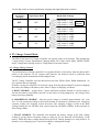
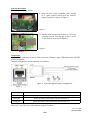
1. Open the case of the controller, there should
be a small control board near the Remote
Signal Terminal as shown in figure 5.
Figure. 5
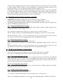
2. On the small control board, there is a sky blue
color dip switch. Turn the dip switch 1 and 2
to ON position as shown in figure 6.
Figure. 6
Connection
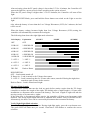
Use the RJ-45 connector (8-pin) to make extension of Battery status LED and control ON/OFF
of the Equipments.
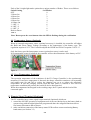
The pins configuration and connection are as follow:
Figure. 8 Connection diagram of RJ-45 to Equipments.
Figure. 7
Pin 1 & 2
On/Off Control Signal synchronized with Night-light Mode
Pin 7 & 4
High/Low control signal (12V, 0V) up to 1A, synchronized with Night Light mode
Pin 6 & 4
Shows the battery status Red LED (See Section 3.2)
Pin 8 & 4
Shows the battery status Green LED (See Section 3.2)
Table 7 Pins configuration
Note: Pin 3 and 5 are not used in Remote Signal Terminal.
Rev. 1.0 11/2004
7673-6112-0562
END