1
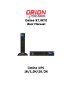
User Manual Centurion RT Online UPS 1000/2000/3000 Uninterruptible Power Supply System IMPORTANT Download latest software www.powershield.com.au/downloads NetGuard® 0 www.powershield.com.au Introduction Thank you for choosing PowerShield. PowerShield Centurion RT UPS series are designed to provide the highest level of protection against disturbances found on electrical power supply lines. It is suitable for most applications including IT, security, telephone, broadcasting, medical etc. The Centurion RT UPS series are designed to provide the most comprehensive protection for your valuable electronic equipment, hardware, software and data from harmful disturbances found on AC power lines including blackouts, power sags, power surges, under voltage, over voltage, line noise, frequency variation, switching transients and harmonic distortions. The Centurion RTs true online double conversion topology will continuously protect your equipment by internally isolating your equipment from the utility power ensuring that all your equipment always receives clean, uninterrupted and stable power. Very Important !! : WARRANTY REGISTRATION In order to validate product warranty, it is essential that you register your UPS on line. Please Visit PowerShield on line product warranty web page at www.powershield.com.au/register-products/ This user manual contains instructions relating to safety, installation, operation, maintenance and warranty of this product. Please keep this manual in a safe place for future references. 1 www.powershield.com.au Special Symbols The following symbols are used on the UPS to alert you to important information. RISK OF ELECTRIC SHOCK Indicates that a risk of electric shock is present and the associated warning should be observed CAUTION; REFER TO OPERATOR’S MANUAL Refer to your operator’s manual for additional information, such as important operating and maintenance procedures. SAFETY EARTHING TERMINAL Indicates the primary safety ground. This symbol indicates that you should not discard the UPS or the UPS batteries in the trash. The UPS may contain sealed, lead-acid batteries. Batteries must be recycled. 2 www.powershield.com.au Table of Contents 1. Important Safety Warning......................................................................... 4 1-1. Transportation ...................................................................................... 4 1-2. Preparation ........................................................................................... 4 1-3. Installation ........................................................................................... 4 1-4. Operation ............................................................................................. 5 1-5. Maintenance, service and faults ............................................................. 5 2. Installation and setup ............................................................................... 6 2-1 Rear panel view ..................................................................................... 6 2-2. Installing the UPS ................................................................................. 7 2-3. Setting up the UPS ................................................................................ 8 2-4 Battery Replacement ............................................................................. 11 2-5 Battery Kit Assembly (option)................................................................. 12 3. Operations .............................................................................................. 14 3-1. Button operation .................................................................................. 14 3-2. LCD Panel ............................................................................................ 14 3-3. Audible Alarm ...................................................................................... 16 3-4. LCD display wordings index .................................................................. 16 3-5. UPS Parameter Settings ........................................................................ 16 3-6. Operating Mode Description .................................................................. 21 3-7. Faults Reference Code .......................................................................... 22 3-8. Warning indicator ................................................................................. 22 4. Troubleshooting ...................................................................................... 23 5. Storage and Maintenance ........................................................................ 25 5-1. Operation ............................................................................................ 25 5-2. Storage ............................................................................................... 25 6. Specifications.......................................................................................... 26 3 www.powershield.com.au 1. Important Safety Warning For safety reasons, it is essential to comply with all warnings and operating instructions listed in this manual. Do not operate the UPS unit before carefully reading through all safety information and operating instructions. It is recommended that you save and or backup this manual for future reference. 1-1. Transportation Transport the UPS system using only the original packaging to protect against shock and impact. Handling Safety Do not lift heavy loads without assistance. This equipment is intended for installation in a controlled temperature indoor area free from conductive contaminants. 1-2. Preparation The UPS system must be absolutely dry before installation. As condensation may occur if the UPS system is moved directly from cold to warm environments, allow at least two hours for the UPS system to acclimate to the environment. Do not install the UPS system near water or in moist environments. Do not install the UPS system where it would be exposed to direct sunlight or near heaters. Do not block ventilation holes in the UPS housing. 1-3. Installation Do not connect appliances or devices that may overload the UPS system (e.g. laser printers) to the UPS output sockets. To ensure against physical hazards, place cables safely such that persons cannot accidentally trip over or step on them. Do not connect domestic appliances such as hair dryers to UPS output sockets. The UPS can be operated by any individual without previous experience. Always connect the UPS system to an earthed shockproof outlet that is easily accessible and close to the UPS system. Use only VDE-tested, CE-marked mains cable (e.g. the mains cable of your computer) to connect the UPS system to the building wiring outlet (shockproof outlet). Use only VDE-tested, CE-marked power cables to connect the loads to the UPS system. When installing the equipment, ensure that the sum of the leakage currents of the UPS and the connected devices do not exceed 3.5mA. 4 www.powershield.com.au 1-4. Operation Do not disconnect the mains cable on the UPS system or the building wiring outlet (shockproof socket outlet) during operations as this will cancel and invalidate the protective earth of the UPS system and of all connected loads. As the UPS system features its own internal current source (high capacity batteries), the UPS output sockets may be electrically live even if the UPS system is not connected to the building wiring outlet. In order to fully disconnect the UPS system, first press the OFF/Enter button to disconnect the mains. Prevent fluids or other foreign objects from entering inside the UPS system. 1-5. Maintenance, service and faults The UPS system operates with hazardous voltages. Repairs should only be carried out by qualified maintenance personnel. Caution - risk of electric shock. Even after the unit is disconnected from the mains, building wiring outlet, components inside the UPS system are still connected to the battery and electrically live and dangerous. Before carrying out any kind of service and/or maintenance; switch off mains power, then disconnect the batteries and verify that no hazardous voltages are present at the terminals of the large storage capacitors (the BUS-capacitors). Only persons who are adequately familiar with high capacity batteries, and with the understanding of the required precautionary measures outlined below, are permitted to replace batteries and supervise operations. Unauthorized persons must be kept well away from the batteries. Caution - risk of electric shock. The battery circuit is not isolated from the input voltage. Hazardous voltages may occur between the battery terminals and the ground. Before touching, always verify that no voltage is present! Batteries may cause electric shock and have very high short-circuit currents. When working with batteries always ensure the following precautionary measures are adhered to: -remove all jewellery items (wristwatches, rings and metal objects) -use only tools with insulated grips and handles. When changing batteries, always install the same model and type of batteries. Do not attempt to dispose of batteries by burning as they may explode. Do not open or destroy batteries. Escaping electrolyte can cause injury to the skin and eyes and may be toxic. Replacement fuses must be of the same type and amperage (current rating) in order to avoid fire hazards. Do not dismantle the UPS system. 5 www.powershield.com.au 2. Installation and setup NOTE: Inspect the unit before installation for any evidence of mistreatment or damage of contents inside the packaging during transport. Store the original package in a safe place for future use. NOTE: There are two different types of online UPS: standard and long-run models. Please refer to the following model table. Model No. PSCERT1000 PSCERT2000 PSCERT3000 Type Standard Model No. PSCERT1000L PSCERT2000L PSCERT3000L Type Long-run 2-1 Rear panel view AC Input - 10Amp IEC PSCERT1000(L) AC Input - 15 Amp IEC PSCERT3000(L) 1. 2. 3. 4. 5. 6. 7. 8. 9. AC Input - 10Amp IEC PSCERT2000 AC Input - 15 Amp IEC PSCERT2000L Programmable outlets: connect to non-critical loads. Output receptacles: connect to mission-critical loads. AC input Input circuit breaker Emergency power off function connector (EPO) USB communication port RS-232 communication port SNMP intelligent slot External battery connector 6 www.powershield.com.au 2-2. Installing the UPS For safety, the UPS is shipped from the factory with the battery wires disconnected. Follow the steps below to re-connect the battery wires before installing the UPS. Step 1 Step 2 Step 3 Remove front panel. Re-connect battery wires and connect the AC input. Replace front panel on the unit. This UPS can be used as either a stand-alone tower or rack mounted in a 19” chassis. Choose from the appropriate installation instructions below to position the UPS accordingly. Rack-mount Installation Install UPS alone Install UPS and external battery Contact www.powershield.com.au on 1300-305-393 for optional PowerShield Rail Kit - PSRK 7 www.powershield.com.au Tower Installation Step 1 Step 2 Step 3 Install UPS and external battery 2-3. Setting up the UPS Step 1: UPS input connection When connecting the UPS to the mains supply always use a three pin plug, three-wire, grounded receptacle and avoid using extension cords. Step 2: UPS output connection There are two kinds of socket-type outputs: programmable outlets (white coloured outlets) and general outlets (black coloured outlets). Connect non-critical devices to the programmable outlets and critical devices to the general outlets. The backup time to critical devices may be extended during power failure by setting shorter backup time for non-critical devices. Step 3: Communication connection Communication port: USB port RS-232 port Intelligent slot To allow for unattended UPS shutdown/start-up and status monitoring, connect the communication cable on one end to the USB or RS-232 port of the UPS and the other to the USB or RS232 communication port of your PC. With the monitoring software installed, you can 8 www.powershield.com.au schedule UPS shutdown/start-up and monitor UPS status through the PC. The UPS is equipped with an intelligent slot to accommodate either an SNMP or AS400 card. When installed, either the SNMP or AS400 card will provide advanced communication and monitoring options for the UPS. Please Note: The USB port and RS-232 port can NOT operate at the same time. Step 4: Disable and enable EPO function For normal UPS operation, connect pin 1 and pin 2 (closed switch). To activate Emergency Power Off (EPO) function, cut the wire between pin 1 and pin 2 (open switch). Illustration is in the closed switch position for normal UPS operation. Step 5: External Battery Bank connection Connect the UPS to the first Battery Bank and daisy chain any additional Battery Banks in parallel using the external battery cables provided. UPS External battery cable Battery Bank External battery cable Battery Bank BATTERY BANKS PSRTBB6 suits PSCERT1000(L) PSRTBB12 suits PSCERT2000(L) and PSCERT3000(L) 9 www.powershield.com.au Step 6: Turn on the UPS Press the ON/Mute button on the front panel for two seconds to power on the UPS. Note: The battery will fully charge during the first five hours of normal operation. Do not expect full battery run capability during this initial charge period. Step 7: Software Installation For optimal computer system protection, install the UPS monitoring software to fully configure UPS shutdown. Follow the steps below to download and install NetGuard monitoring software: 1. Go to the website www.powershield.com.au 2. Click Downloads software icon and choose your required OS to download the NetGuard software in the http://www.powershield.com.au/downloads/ downloads page. 3. Follow the on-screen instructions to install the NetGuard software. 4. When the computer re-starts, the NetGuard monitoring software will appear as an orange plug icon located in the system tray, near the clock. 10 www.powershield.com.au 2-4 Battery Replacement NOTICE: The UPS is equipped with a hot-swappable battery design so the internal batteries can be replaced without shutting down the UPS or connected loads. Replacement is a safe procedure, isolated from electrical hazards. CAUTION!! Consider all warnings, cautions and notes before replacing batteries. Note: The equipment is not protected from power outages during battery disconnection. Step 1 Step 2 Step 3 Remove front panel. Disconnect battery wires. Pull out the battery box by removing the two screws on the front panel. Step 4 Step 5 Step 6 Remove the top cover of battery box and replace the batteries inside. After replacing the batteries, slide the battery box back in the original location and screw it tightly. Re-connect the battery wires. Step 7 Replace the front panel on the unit. 11 www.powershield.com.au 2-5 Battery Kit Assembly (option) Call Service on 1300-305-393 or contact www.powershield.com.au for fully assembled replacement battery kits. Alternatively, follow the procedures below to assemble new battery kits before replacing used UPS batteries kits. 3-battery kit Step 1: Remove adhesive tapes. Step 2: Connect all battery terminals by following below chart. Tapes Tapes Step 3: Put assembled battery packs on one side of plastic shells and insert one more defect battery on the space. Step 4: Cover the other side of plastic shell as below chart. Then, battery kit is assembly well. Defect battery 6-battery kit Step 1: Remove adhesive tapes. Step 2: Connect all battery terminals by following the chart below. Tapes Tapes 12 www.powershield.com.au Step 3: Place assembled battery packs on one side of the plastic shells. Step 4: Cover the other side of the plastic shell as shown below so that the battery kit assembly is ready for installation. 13 www.powershield.com.au 3. Operations 3-1. Button operation Button View Button Function Turn on the UPS: Press and hold ON/Mute button for at least 2 seconds to turn on the UPS. Mute the alarm: After the UPS is in battery mode, press and hold this button for at least 5 seconds to disable or enable the UPS ON Battery warning. This does not Mute any other warnings or errors. ON/Mute Button Up key: Press this button to display previous selection in UPS setting mode. Switch to UPS self-test mode: Press ON/Mute buttons for 5 seconds to enter UPS self-testing while in AC mode, ECO mode, AECO mode, or converter mode. Turn off the UPS: Press and hold this button for at least 2 seconds to turn off the UPS. UPS will switch off to standby mode under normal power or transfer to bypass mode if the Bypass setting has been OFF/Enter Button enabled. Confirm selection key: Press this button to confirm selection in UPS setting mode. Switch LCD message: Press this button to change the LCD message Select Button for input voltage, input frequency, battery voltage, output voltage, and output frequency. Select Button Setting mode: Press and hold this button for 5 seconds to enter UPS function used in setting mode when in Standby or Bypass mode. Bypass Mode or Down key: Press this button to display next selection in UPS setting Standby Mode mode. Switch to bypass mode: With the mains power switched ON, press ON/Mute + Select ON/Mute and Select buttons simultaneously for 5 seconds. The UPS Button will enter Bypass Mode. This action will be ineffective when the input voltage is out of the acceptable range. 3-2. LCD Panel Rack Display Load info Input/output and Battery info UPS status Tower Display Battery info Battery info Warning & Fault info/ Setting operation Backup time info Load info Input/output and Battery info Warning & Fault info/ Setting operation UPS status Backup time info 14 www.powershield.com.au Display Function Backup remaining time information Indicates the remaining backup time in pie chart. Indicates the remaining backup time in numbers or digits. H: hours, M: minute Warning & Fault information Indicates that a warning and fault occurs. Indicates the warning and fault codes as listed in detail in section 3-7 and 3-8. Setting Operation Indicates the setting operation. Input/Output & Battery information Indicates the input/output voltage, input/output frequency, and battery voltage. V: voltage, Hz: frequency Load information Indicates the load level by 0-25%, 26-50%, 51-75%, and 76-100%. Indicates overload. Indicates the load or the UPS output is short circuited. UPS status Indicates that programmable management outlets are working. Indicates the UPS is working in line mode. Indicates the UPS is working in converter mode. Indicates the UPS is working in bypass mode. Indicates the UPS powers the output directly from the mains Indicates the UPS alarm is disabled. Indicates the battery charger is working. Battery information Indicates the Battery level by 0-25%, 26-50%, 51-75%, and 76-100%. Indicates low battery. Indicates there is something wrong with battery. 15 www.powershield.com.au 3-3. Audible Alarm Battery Mode 2 beeps every 30 seconds Bypass Mode 1 beep every 10 seconds Low Battery Rapid one beep every second Overload 2 short beeps every 2 seconds Fault Continuously sounding 3-4. LCD display wordings index Abbreviation Display content Meaning ENA Enable DIS Disable ESC Escape RAC Rack display TOE Tower display AON Backlight always on AUT Backlight automatic on/off EP EPO TP Over Temperature CH Charger Failure SF Site Fault FU Frequency Unstable in Bypass Mode EE EEPROM error 3-5. UPS Parameter Settings Parameter 2 Parameter 1 There are two parameters used to set up the UPS. Parameter 1: Is used for program alternatives. Parameter 2: Is used for setting information display. 16 www.powershield.com.au 01: Output voltage setting Interface Setting For 208/220/230/240 VAC models, you may choose the following output voltage: 208: sets output voltage to 208Vac 220: sets output voltage to 220Vac 230: sets output voltage to 230Vac 240: sets output voltage to 240Vac (Default setting) 02: Frequency Converter enable/disable Interface Setting CF ENA: converter mode enable CF DIS: converter mode disable (Default setting) 03: Output frequency setting Interface Setting The frequency may be set in battery mode: BAT 50: sets output frequency to 50Hz BAT 60: sets output frequency to 60Hz If converter mode is enabled, output frequency can be selected: CF 50: sets output frequency to 50Hz CF 60: sets output frequency to 60Hz 04: ECO enable/disable Interface Setting ENA: ECO mode enable DIS: ECO mode disable (Default setting) 17 www.powershield.com.au 05: AECO enable/disable Interface Setting ENA: Advanced ECO mode enable DIS: Advanced ECO mode disable (Default setting) 06: Bypass mode enable/disable Interface Setting ENA: Bypass mode enable DIS: Bypass mode disable (Default setting) 07: Programmable outlets enable/disable Interface Setting ENA: Programmable outlets enable See 3-5-1 DIS: Programmable outlets disable (Default setting) 08: Programmable outlets setting Interface Setting 0-999: setting the backup time limits in minutes from 0-999 for programmable outlets which connect to non-critical devices in battery mode. 18 www.powershield.com.au 09: LCD display direction setting Interface Setting RAC: the LCD display is horizontal. TOE: the LCD display is vertical. (Default setting) 10: Acceptable input voltage range setting Interface Setting For 208/220/230/240 VAC models, choose from the following Acceptable input voltage range: 110/300 alternating flashing: acceptable input voltage range is from 110V to 300V; (Default setting) 160/260 alternating flashing: acceptable input voltage range is 160V to 260V; 170/270 alternating flashing: acceptable input voltage range is 170V to 270V; 11: LCD display backlight setting Interface Setting Aon: LCD display backlight is on all the time. Aut: LCD display backlight will turn off after 60 seconds if no buttons are pressed. (Default setting) 12: Autonomy Limitation setting Interface Setting 0-999:Setting the backup time limits in minutes from 0 to 999 in battery mode. 0:Maximum 10 seconds of backup time 999:Disable autonomy limitation function (Default setting) 00: Exit setting 19 www.powershield.com.au 3-5-1 Steps for setting programmable outlet ( White Coloured Outlets ) Step 1: Before entering setting mode, ensure the UPS is in either Bypass or Stand-by mode (off-charging) and make sure the battery is connected. The LCD display is shown at right. Step 2: Press and hold the “Select” button for 5 seconds to enter Setting mode. Step 3: Press the “Up“ button (ON/MUTE) to switch to "07" of program list. Then press “Enter“ button to enter value setting of parameter 2. Press the “Up” button to change the value to “ENA” to enable the programmable outlet function. Then press “Enter” button again to confirm the setting. Step 4: Press the “Up“ button (ON/MUTE) again to switch to "08" of program list. Then press “Enter“ button for setting programmable outlet time. Push “Up” button to change the value of backup time according to your demand. Then press “Enter” to confirm the setting. Step 5: Press “Up“ button (ON/MUTE) to switch to "00" of program list. Then press “Enter” button to exit setting menu. Step 6: Disconnect AC input and wait until the LCD display is off. The new setting will be activated when the UPS is turned on again. 20 www.powershield.com.au 3-6. Operating Mode Description Operating Description mode Online mode When the input voltage is within acceptable range, UPS will provide pure and stable AC power to output. The UPS will also charge the battery in online mode. ECO mode (Efficiency Corrective Optimizer) When the input voltage is within setting range (±3%Vo), UPS will bypass voltage to output for energy saving. PFC and INVERTER are still active in this mode. AECO mode (Advanced Efficiency Corrective Optimizer) When the input voltage is within setting range (±3%Vo), UPS will bypass voltage to output for energy saving. PFC and INVERTER are off in this mode. Frequency Converter mode (Rack) When input frequency is within 40 Hz to 70 Hz, the UPS can be set at a constant output frequency of 50 Hz or 60 Hz. The UPS will still charge the battery in this mode. Battery mode When the input voltage is beyond the acceptable range or power failure and alarm is sounding 2 beeps every 30 seconds, UPS will backup power from the battery. Bypass mode When input voltage is within acceptable range but UPS is in overload, UPS will enter bypass mode or bypass mode can be set by front panel. Alarm is sounding every 10 seconds. Standby mode UPS is powered off without providing output power, but the battery is still being charged. LCD display Rack Display Tower Display 21 www.powershield.com.au Fault mode The UPS is in fault mode when no output power is supplied from the UPS and the fault icon flashes on the LCD display. The UPS status information continues to be displayed on the screen. 3-7. Faults Reference Code Fault event Bus Bus Bus Bus start fail over under unbalance Fault code 01 02 03 04 Icon x x x x Low Inverter voltage Inverter output short Battery voltage too high Battery voltage too low 05 11 12 x x x Over temperature Overload Bus short Inverter soft start fail High Inverter voltage Fault event Fault code 13 14 27 28 Icon 41 43 x x x 3-8. Warning indicator Warning Low Battery Icon (flashing) Alarm Rapid one beep every second Overload 2 short beeps every 2 second Battery is not connected 2 short beeps every 2 second Overcharge Continuously sounding Site wiring fault 2 short beeps every 2 second EPO enable 2 short beeps every 2 second Over temperature Continuously sounding Charger failure Continuously sounding Battery Fault Continuously sounding Bypass Out Range 2 short beeps every 2 second Bypass Frequency Unstable 2 short beeps every 2 second EEPROM error 2 short beeps every 2 second 22 www.powershield.com.au 4. Troubleshooting Use the table below to diagnose the UPS system for symptoms and problems. Symptom Possible cause Remedy No indication and alarm even The AC input power is not Check if input power cord though the mains supply is connected well. firmly connected to the normal. mains. The AC input is connected Plug AC input power cord to the UPS output. to AC input correctly. The icon and the warning code flashing on LCD display and alarm is sounding 2 short beeps every 2 seconds. The icon and flashing on LCD display and alarm is sounding 2 short beeps every 2 seconds. EPO function is activated. Set the circuit in closed position to disable EPO function. Line and neutral conductors of UPS input are reversed. Check mains power socket and or building wiring and then reconnect to UPS system. The external or internal Check if all batteries are The icon and flashing battery is incorrectly connected well. on LCD display and alarm is connected. sounding 2 short beeps every 2 seconds. Fault code is shown as 27 and the Battery voltage is too high Contact your dealer. or the charger is faulty. icon is lighting on LCD display and alarm is continuously sounding. Fault code is shown as 28 and the Battery voltage is too low Contact your dealer. or the charger is faulty. icon is lighting on LCD display and alarm is continuously sounding. The icons of and are flashing on LCD display and alarm is sounding 2 short beeps every 2 seconds. UPS is overloading Remove excess loads from UPS output. UPS is overloaded. Devices Remove excess loads from connected to the UPS are UPS output. fed directly by the electrical network via the Bypass. After repetitive overloads, Remove excess loads from the UPS is locked in the UPS output first. Then shut Bypass mode. Connected down the UPS and restart devices are fed directly by it. the mains. 23 www.powershield.com.au Symptom Possible cause Fault code is shown as 43 and The icon is lighting on LCD display and alarm is continuously sounding. Fault code is shown as 14 and alarm is continuously sounding. The UPS shut down automatically because of overload at the UPS output. The UPS shut down automatically because short circuit occurs on the UPS output. Fault code is shown as 01, 02, 03, A UPS internal fault has 04, 05, 11, 12, 13 and 41 on LCD occurred. There are two display and alarm is continuously possible results: sounding. 1. The load is still supplied, but directly from AC power via bypass. 2. The load is no longer supplied. Battery backup time is shorter Batteries are not fully than nominal value charged Battery defect Remedy Remove excess loads from UPS output and restart it. Check output wiring and if connected devices are in short circuit status. Contact your dealer Charge the batteries for at least 5 hours and then check capacity. If the problem still persists, consult your dealer. Contact your dealer to replace the batteries. 24 www.powershield.com.au 5. Storage and Maintenance 5-1. Operation The UPS system contains no user-serviceable parts. Please contact your dealer if the battery service life (3~5 years at 25°C ambient temperature) has been exceeded, as the batteries must be replaced. Be sure to deliver the spent battery to a recycling facility or ship it to your dealer in the replacement battery packing material. 5-2. Storage Before storing, charge the UPS for 5 hours. Store the UPS covered and upright in a cool, dry location. During storage, recharge the battery in accordance with the following table: Storage Temperature -25°C - 40°C 40°C - 45°C Recharge Frequency Every 3 months Every 2 months Charging Duration 1-2 hours 1-2 hours 25 www.powershield.com.au 6. Specifications BaTTerY BanKS CENTURION rT Model PSCERT1000 Capacity PSCERT1000(L) PSCERT2000 1000VA/900W Topology PSCERT2000(L) PSCERT3000 PSCERT3000(L) 3000VA/2700W 2000VA/1800W True online double - conversion, Pure Sine Wave PSRTBB6 PSRTBB12 Suits PSCERT1000 Suits PSCERT2000 and PSCERT3000 12 V*9AH (x 6) 12 V*9AH (x 12) (480 x 438 x 88) mm (600 x 438 x 88) mm 22kg 42kg InPUT Low Line Trasfer 160Vac / 140Vac / 120Vac / 110Vac ± 5% (based on load percentage 100% - 80% / 80% - 70% / 70% - 60% / 60% - 0) 170Vac / 150Vac / 130Vac / 120Vac ± 5% Low Line Comeback Voltage Range High Line Trasfer 300Vac ± 5% High Line Comeback 290Vac ± 5% Frequency Range 40Hz - 70Hz Single phase with ground Phase >0.99 @ nominal voltage (100% load) Power Factor Correction Output Power Factor: 0.9 oUTPUT Output Voltage (AC Mode) 240Vac (Selectable 208/220/230/240Vac) Voltage Regulation (Batt. Mode) ±1% Frequency Range (Batt. Mode) 50Hz or 60Hz ±1Hz 5:1 (max.) Current Crest Ratio 4ms (Typical) Transfer Time eFFICIenCY ECO Mode (Advanced) 98% 98% 98% Battery Mode 86% 87% 87% BATTERY Battery Type & Number 12 V*9AH (x 3) Typical Recharge Time Charging Current (max.) 12 V*9AH (x 6) 12 V*9AH (x 6) 4 hours recover to 90% capacity (for standard model only) Standard Model -1.5Amp, Long Run Model - 1Amp/2Amp /4Amp/6Amp (factory default is 6Amp) ProTeCTIon Full Protection Overload, discharge, thermal, short circuit and overcharge protection 984 Joules / 22000 Amps Surge Protection COMMUNICATIONS & MANAGEMENT Interface USB or RS232 as standard, Intelligent slot for PSSNMP, PSModbus or PSAS400 dry contact Software PowerShield NetGuard® software - supports Windows based operating systems, Linux, Unix and Mac LCD Display/Alarm UPS Status, Load & Battery Level, Input/Output Voltage, Batt. Time Remaining and Fault Indicators Battery Mode, Bypass Mode, Low Battery (Batt. Mode), Fault, Overload Audible Alarm PHYSICaL Dimension (D x W x H) (480 x 438 x 88) mm Weight 18kg 10kg (600 x 438 x 88) mm 29.6kg 13.8kg (600 x 438 x 88) mm 29.6kg 13.8kg OPERATING envIronmenT Temperature Humidity Noise Level 0 - 40°C 20 - 90% (RH Non-condensing) < 50dBA @ 1 Meter COMPLIANCE Safety EN62040-1-1 2003, IEC60950-1-1 EMC EN62040-2 2006 RoHS Directive 2011/65/EU 26 www.powershield.com.au Power Shield Pty Ltd Warranty Terms & Conditions (PSW28012012) SERVICE / WARRANTY (Australia) (Tel) 1300-305-393 Warranty Conditions 1. Power Shield product are warranted for certain specified period (see item 15 below) against failure due to faulty materials or workmanship from the invoice date from the Power Shield Store. Power Shields products are covered by a warranty in addition to all rights available to you by statute. 2. If, within the warranty period, the product does not meet the specification above and the product was installed and operated in accordance with Power Shield and Australian standards and procedures, then Power Shield will, correct any defects due to material or workmanship. 3. If the product has been modified, recalibrated, repaired, opened or tampered with in any way by the customer then its warranty will be void. 4. If the product has been damaged during transport then warranty will be void. 5. If product failed due to fire, earthquake, flood, direct lighting strike, terrorism, pollution, exposed under poison gas, and incorrect utility voltage then warranty will be void. 6. Batteries must be operated within the technical specification limits of the manufacturer and must be fully re-charged at least every three months during storage. 7. If Power Shield at its sole discretion determines that the product has failed, under Power Shield warranty conditions then Power Shield will at its option repair or replace the faulty unit 8. Power Shield will, at its sole discretion, replace the faulty product with an equal or equivalent model of a similar age and condition. 9. If the product, has failed due to reasons that Power Shield at its sole discretion, determines to be outside of warranty conditions, or is found to be not faulty then a minimum inspection and handling fee will be charged and also freight will be for the customer’s account. 10. Blown fuses are usually as a result of overload and are not considered a warranty condition and a handling and inspection charge will apply as above 11. For hardwired products, larger than 3KVA, the warranty covers onsite repair for metro areas in capital cities only. For equipment installed in remote locations Power Shield may, at its sole discretion, request that the product be returned to a Power Shield service centre at the customer’s cost, 12. Power Shield UPS products are not failsafe devices. Although well designed and manufactured, like all electrical, electronic and mechanical devices it has the potential to fail. This should be taken into consideration when designing any critical system 13. Subject to the applicable Law, in no event shall Power Shield Pty Ltd, it’s officers, directors, affiliates or employees be liable for any form of indirect, special, consequential or punitive damages, arising out of the use, service or installation, of the products, whether such damages arise in contract or tort, irrespective of fault, negligence or strict liability or whether Power Shield Pty Ltd has been advised in advance of the possibility of such damages. Specifically, Power Shield Pty Ltd is not liable for any costs, such as lost profits or revenue, loss of equipment, loss of use of equipment, loss of software, loss of data, costs of substitution, claims by third parties, or otherwise. 14. Our products come with guarantees that cannot be excluded under the Australian Consumer Law. You are entitled to a replacement or refund for a major failure and compensation for any other reasonably foreseeable loss or damage. You are also entitled to have the products repaired or replaced if the products fail to be of acceptable quality and the failure does not amount to a major failure. 15. Warranty period commences from the date Power Shield invoices the goods ZapGuard Range: 1 year CompuGuard, SafeGuard, Defender, Commander, Centurion: 2 years Platinum Range: 1 year Gamatronic Range: 1 year To claim a warranty our contact details are as follows Call Service on 1300-305-393 Or Visit www.powershield.com.au/rmaform/ to process an RMA Or Power Shield Pty Ltd (Head Office) U3, 205 Camboon Rd Malaga, WA 6090 Any claim for expenses must be provided to us in writing and should be sent to our office, detailed above. 27 www.powershield.com.au