1
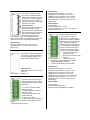
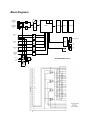
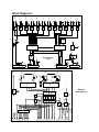
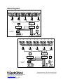
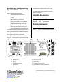
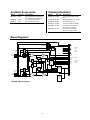
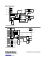
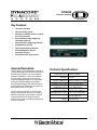
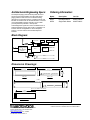
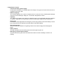
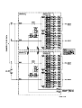
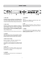
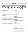
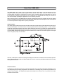
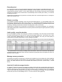
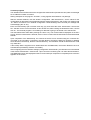
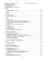
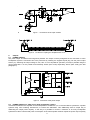
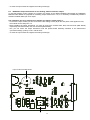
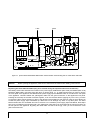
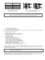
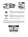
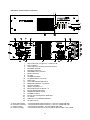
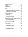
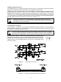
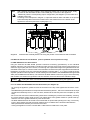
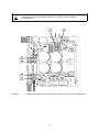
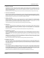
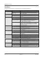
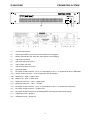
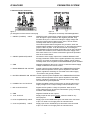
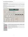
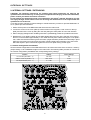
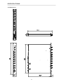
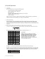
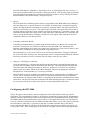
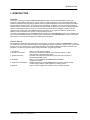
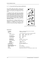
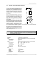
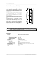
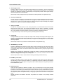
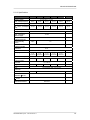
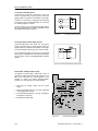
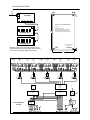
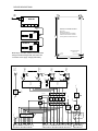
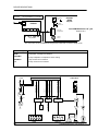
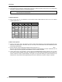
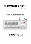
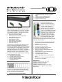
19
20
21
22
23
A
CIRCUIT ⊥ TO CHASSIS SWITCH
DC INPUT 24V = (battery)
IDENT ADDRESS switch
REMOTE CONTROL connectors
STATUS indicator
locking screws power supply printed board
B
locking screws INPUT MODULE
Contents
Performance Features......................................................................................................................... 23
Indicators, controls and connections .................................................................................................... 25
1.
Utilization ......................................................................................................................................... 27
2.
Installation ........................................................................................................................................ 27
3.
Before the first operation ..................................................................................................................... 27
3.1 Mains operation .......................................................................................................................... 27
3.2 Battery operation 24V DC ............................................................................................................. 28
4.
INPUT ............................................................................................................................................... 28
5.
Outputs ............................................................................................................................................. 29
5.1 POWER OUTPUT........................................................................................................................ 29
5.2 POWER OUTPUT for 100V (70V or 50V) loudspeaker systems........................................................ 29
5.3 SINGLE CALL and obligatory reception relays OVERRIDE BYPASS................................................ 29
5.4 POWER OUTPUT for low impedance loudspeaker systems............................................................. 29
5.5 MONITOR output ......................................................................................................................... 30
5.6 REMOTE CONTROL connector (only NRS 90225) .......................................................................... 30
6.
Indicators .......................................................................................................................................... 30
6.1 STANDBY indicator...................................................................................................................... 30
6.2 READY indicator.......................................................................................................................... 30
6.3 PROTECT indicator...................................................................................................................... 30
6.4 GROUND FAULT indicator............................................................................................................ 30
6.5 Aussteuerungskontrolle und CLIP-Anzeige ..................................................................................... 31
7.
Switching the output voltage ................................................................................................................ 31
8.
Enhanced application field................................................................................................................... 32
8.1 General input module NRS 90225.................................................................................................. 32
8.2 Remote module NRS 90222.......................................................................................................... 32
8.3 NRS 90208 input transformer for the floating, balanced input ............................................................ 33
8.4 NRS 90227 output transformer for the floating, balanced monitor output ............................................ 33
8.5 NRS 90224 pilot tone and ground fault surveillance.......................................................................... 35
8.5.1 Pilot tone surveillance.......................................................................................................... 35
8.5.2 Ground fault surveillance...................................................................................................... 35
9.
19"-case and 19“-rack shelf system installation..................................................................................... 38
10.
Ground lift switch CIRCUIT ⊥ TO CHASSIS SWITCH.............................................................................. 38
11.
Fuses................................................................................................................................................ 38
11.1 Fuses in the DPA....................................................................................................................... 38
11.2 Fuses in the DPA....................................................................................................................... 38
12.
Power amplifier specifications .............................................................................................................. 42
12.1 DPA 4120 power amplifier 200 W................................................................................................. 42
12.2 DPA 4140 power amplifier 400 W................................................................................................. 43
13.
Extension specifications ..................................................................................................................... 44
13.1 NRS 90225 general input module................................................................................................. 44
13.2 NRS 90222 remote module ......................................................................................................... 44
13.3 NRS 90208 input transformer for floating, balanced input ................................................................ 44
13.4 NRS 90227 output transformer for floating, balanced monitor output ................................................ 44
13.5 NRS 90224 pilot tone and ground fault surveillance........................................................................ 44
14.
Block diagrams .................................................................................................................................. 67
14.1 Power amplifiers DPA 4120 / DPA 4140 ........................................................................................ 67
14.2 NRS 90225 general input module................................................................................................. 68
26