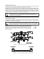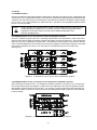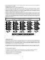
1
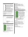
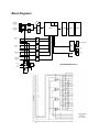
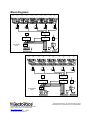
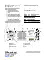
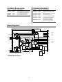
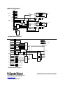
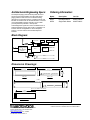
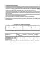
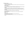
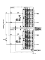
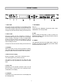
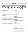
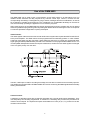
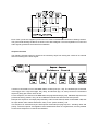
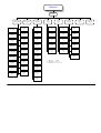
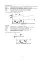
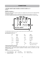
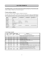
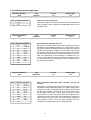
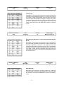
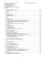
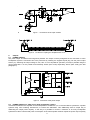
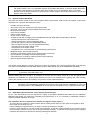
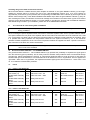
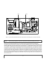
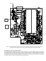
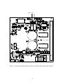
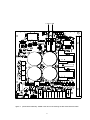
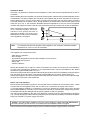
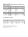
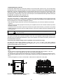
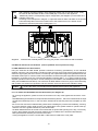
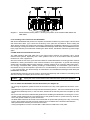
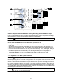
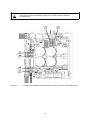
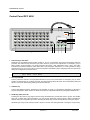
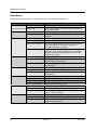
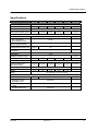
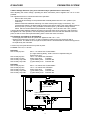
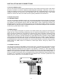
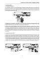
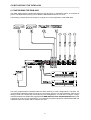
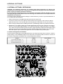
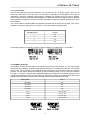
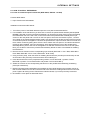
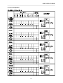
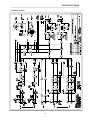
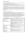
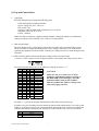
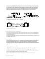
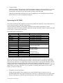
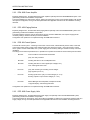
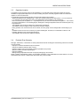
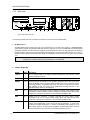
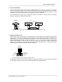
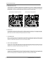
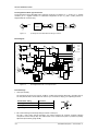
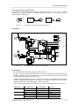
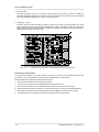
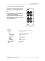
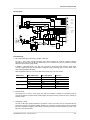
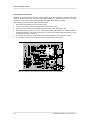
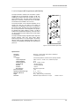
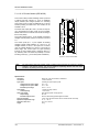
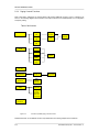
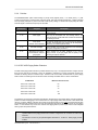
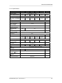
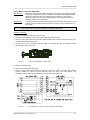
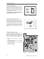
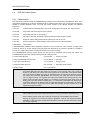
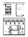
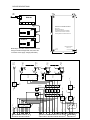
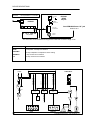
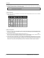
DEVICE DESCRIPTIONS
Pin-Assignment Of XLRM-Type Connectors:
The LINE output XLR-connectors' pin-assignment is as follows: pin 1 = screen, Pin 2 = positive conductor, pin 3 =
negative conductor. In unbalanced configuration the pins 3 (-) and 1 (screen) have to be bridged inside the
connected plug.
figure 5.28
pin-assignment of the OUT XLR-connectors
Block diagram:
+U24
R3
2
+12V
1
OUT A
1
OUT B
3
ANALOG
SUPPLY
NRS 90227
-12V
DIGITAL
SUPPLY
+5V
+6dB
0dB
R2
JP1.A
INTERNAL
MONITOR
MCLK
2 CHANNEL
DIGITAL
AUDIO
0dB
+6dB
JP2.A
D
BCLK
WCLK
MUTE A
MON A
A
R5
DOUT
2
3
NRS 90227
4
SPI
+6dB
BOARD
CONTROL
0dB
R4
JP1.B
+6dB
RES
0dB
MON B
MUTE B
JP2.B
BOARD
ID
figure 5.29
block diagram of the 2-channel LINE output module
Setting Output Levels Via Jumpers:
Each of the two outputs' output level can be set to 0 dB or +6 dB using the jumpers JP1 and JP2. Please make
sure to set both jumpers of an output channel (A / B) to the desired position.
When shipped, the output levels for both output channels are factory pre-set to 0 dB (all jumpers are closed).
Jumper
setting Output
JP1, 2-4 / JP2, 2-4 channel A
Open
+6 dB
Closed
0 dB
level
Jumper
setting Output
JP1, 1-3 / JP2, 1-3 channel B
Open
+6 dB
Closed
0 dB
level
Jumper setting for the output assignment: To be used in network installations.
When used in a network environment, the following jumpers have to be open:
OUT A
OUT B
5-24
LK10, LK11
LK 8, LK 9
(applies to printed board assemblies starting with index C!)
PROANNOUNCE System User Handbook 1.1